Article

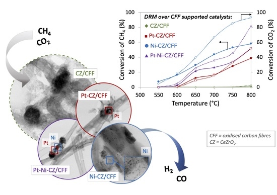
Dry Reforming of Methane over Carbon Fibre-Supported CeZrO2, Ni-CeZrO2, Pt-CeZrO2 and Pt-Ni-CeZrO2 Catalysts

1
Department of Chemistry and Technology of Fuels, Wroclaw University of Science and Technology, Gdańska 7/9, 50-344 Wroclaw, Poland
2
Materials Research Laboratory, Silesian University of Technology, Konarskiego 18A, 44-100 Gliwice, Poland
3
Centre of Polymer and Carbon Materials, Polish Academy of Sciences, M. Curie-Skłodowskiej 34, 41-819 Zabrze, Poland
*
Author to whom correspondence should be addressed.
Catalysts 2021, 11(5), 563; https://doi.org/10.3390/catal11050563
Submission received: 14 April 2021 / Revised: 26 April 2021 / Accepted: 28 April 2021 / Published: 28 April 2021
(This article belongs to the Special Issue Hybrid Metal/Metal Oxide-Carbon Nanomaterials Catalysts)

Abstract

:
Dry reforming of methane (DRM) is one of the most important processes allowing transformation of two most potent greenhouse gases into a synthesis gas. The CH4 and CO2 are converted at high temperatures in the presence of a metal catalyst (usually Ni, also promoted with noble metals, supported over various oxides). The DRM process is not widely used in the gas processing industry because of prompt deactivation of the catalyst owing to carbon deposition and the blockage of the metal active sites. This problem can be hindered by proper design of the catalyst in terms, e.g., of its composition and by providing strong interaction between active metal and catalytic support. The properties of the latter are also crucial for the catalyst’s performance in DRM and the occurrence of parallel reactions such as reverse water gas shift, CO2 deoxidation or carbon formation. In this paper we show for the first time the DRM performance of the ceria-zirconia and metal (Ni and/or Pt) supported on carbon fibres. The obtained Ni and Ni-Pt containing catalysts showed relatively high activity in the studied reaction and high resistance towards carbon deposition.

Graphical Abstract

1. Introduction

Climate change caused by increasing emissions of greenhouse gases (GHGs), such as carbon dioxide (CO2), methane (CH4) and nitrous oxide (N2O), is one of the biggest challenges of our times. The emissions of the two former, i.e., CO2 and CH4, cause more than half of the total greenhouse effect [1] and have the greatest impact on the increase in the average global air temperature [2]. Moreover, those emissions are constantly growing (for CO2, from 22.15 Gt in 1990 to 36.14 Gt in 2014, while for CH4 (as CO2 equivalent), from 6.67 to 8.01 Gt [3]). To minimize GHGs emissions several methods have been developed [4], one of which is dry reforming of methane (DRM) (Equation (1)), which allows converting both GHGs, i.e., CO2 and CH4, into a syngas—a valuable raw material for the chemical industry. During the DRM process, H2 and CO are formed in a ratio close to 1:1, which is appropriate for hydrocarbon production via the Fischer–Tropsch synthesis [5]. The DRM is an extremely endothermic reaction; thus, it requires higher operating temperatures (700–1000 °C) than other reactions of methane conversion to syngas, such as steam reforming (SRM) [6] or partial oxidation (POM) [7].
Moreover, the DRM is followed by several side reactions, including the reverse water-gas shift (RWGS) (Equation (2)) that leads to a H2/CO <1 [8], and a few reactions responsible for carbon formation, and thus, catalyst deactivation [9]. Those are favoured at temperatures above 700 °C methane dehydrogenation (Equation (3)), and privileged below a 550 °C Boudouard reaction (Equation (4)), and reactions of CO/ CO2 hydrogenation (Equations (5) and (6)).
CH4 + CO2 = 2H2 + 2CO      ∆H = 247 kJ/mol
CO2 + H2 ↔ H2O + CO      ∆H = 41.2 kJ/mol
CH4 = C + 2H2      ∆H = 74.9 kJ/mol
2CO = CO2 + C      ∆H = 172.4 kJ/mol
CO + H2 = C + H2O      ∆H = −131.3 kJ/mol
CO2 + 2H2 = C + 2H2O      ∆H = −90 kJ/mol
Catalyst deactivation due to carbon formation may be reduced by proper selection of the active metal that catalyses the DRM reaction, and the support, which stabilizes the active phase, keeps it well dispersed and—in some cases—protects it from carbon deposition. In addition, the application of CO2 excess during DRM can reduce carbon formation [10].
Noble and transition metals are known to promote the DRM reaction [11,12,13]. Those catalysts are usually supported on metal oxides, e.g., Al2O3 [14,15], MgO [16], ZrO2 [17], SiO2 [14] or zeolites [18,19]. Moreover, some studies on DRM catalysts supported on carbon materials such as carbon nanotubes (CNT) [20,21], carbon fibres (CF) [22] or activated carbon (AC) [23] have been reported. The most widely used are nickel catalysts because they are cheap, available and reveal high catalytic activity [24]. Unfortunately, Ni is also prone to carbon deposition because it catalyses all the above-mentioned side reactions occurring during DRM (Equations (3)–(6)). The reaction of carbon formation via CH4 decomposition (Equation (3)) is structure-sensitive [25] and is privileged to occur rather over the Ni (100) and Ni (110) than Ni (111) surface. On the other hand, noble metals are resistant to coke formation [26]. It was found that the amount of carbon deposited on metal catalysts during DRM decreased in the following order: Ni >> Rh > Ir = Ru > Pt ≈ Pd (at 500 °C) and Ni > Pd = Rh > Ir > Pt >> Ru (at 650 °C) [24]. Platinum catalysts were found to be very active in DRM [27,28] and resistant to carbon deposition owing to a very good metal dispersion. The main drawback of noble metals application as DRM catalysts is their high price and limited accessibility. At this point, putting together the transition and noble metals in a proper way may lead to a bimetallic catalyst having improved activity, selectivity, and stability. For example, Pt, Ru or Pd stabilizes nickel in its reduced state which results in improved activity and stability of the DRM catalyst [29,30]. The activity of modified Ni/Al2O3 in DRM was studied by Choi et al. [31]. It was found that the addition of Co, Cu and Zr to the catalyst caused some increase in CH4/CO2 conversions, whereas the introduction of Mo, Ti, Ag and Sn resulted in decreased activity. The Mn-promoted Ni/Al2O3 exhibited slightly lower activity in DRM compared to the unmodified catalyst, but it also showed a significant reduction in coke deposition.
The performance of the catalyst is not limited to the metal active phase only, but it is also linked to the catalytic support that plays different roles in the whole system. From one hand, the support has an impact on the size of the supported metal particle and its dispersion [32]. From the other hand, its acid-base properties determine the method of CO2 activation [12,26,33] and are affecting carbon deposition [34]. It was found by many researchers [35,36,37,38,39] that larger metal particles are more prone to generating carbon deposits during DRM. Thus, it is important to obtain small, well dispersed metal nanoparticles (NPs). It is known that providing Ni NPs of <8 nm inhibits carbon formation but those nanoparticles are also prone to aggregation at temperatures above 700 °C [40]. Improving the metal–support interaction by proper selection of catalytic support can enhance thermodynamic stability of Ni NPs, thus prevent them from sintering, and at the end, affect the catalytic activity in DRM. Ghani et al. [41] reported that adding the MgO to the Ni–Co/Al2O3 caused the formation of MgAl2O3 solid solution that provided high metal–support interaction resulting in high stability and activity of the catalyst and improved carbon suppression during DRM reaction.
Considering the acid-base properties of the support, catalyst deactivation during DRM caused by carbon deposition can be reduced by using metal oxide supports with Lewis basicity [42] such as La2O3 and CeO2. Those oxides increase the ability of the catalysts to chemisorb CO2 that further reacts with carbon to form CO instead of carbon build-up.
Cerium oxide and its solid solution with ZrO2 (i.e., CeZrO2) have been widely used in catalytic reactions, including the DRM [43]. The most important advantages of CeZrO2 over other supports are: high specific surface area (SSA), good thermal stability (owing to the presence of Zr), excellent redox properties, and related to them ability to store and release oxygen [44,45,46,47]. The CeZrO2 has already been considered as a support in DRM catalysts by some researchers [48,49,50,51,52]. The presence of ceria in the DRM catalyst improves its resistance towards carbon deposition, from one hand—by regular scavenging of carbon species from the active sites, and from the other hand—by providing good dispersion of nickel NPs [53,54,55,56,57].
The exposition of active Ni NPs to the DRM reaction mixture is important. Wolfbeisser et al. [49] found that the synthesis method of Ni/CeZrO2 has a significant impact on its morphology and in particular, metal–support interaction. It was found that surfactant-assisted synthesis of the catalyst resulted in some Ni encapsulation and this negatively influenced its performance in DRM. Similarly, Smirnova et al. [58] observed lower CH4/CO2 conversion over the catalyst with a lower amount of Ni exposed to reaction mixture. Therefore, providing good dispersion and exposition of Ni, and strong metal–support interaction is crucial for providing high catalytic activity in DRM reaction. Different approaches have been applied to meet these criteria, one of which is immobilisation of active metal inside the structure of thermally stable metal oxides, e.g., spinels, perovskites or fluorites [59]. However, maintaining the active metal accessible to reagents is challenging.
Another option is deposition of catalytically active phases on crystalline carbon supports that show chemical neutrality, and provide very good charge and heat transfer. Carbon fibres (CF) obtained from polyacrylonitrile (PAN) have been studied as catalytic supports from the early 1980s [60,61]. Since then, a great improvement has been made regarding their thermal resistance. Activated carbon fibres (ACF) have also been used as catalytic supports [62,63,64,65,66,67]. Unlike CF, the ACF show developed specific surface areas that reach up to 3000 m2/g [68]. Production of CF from PAN has an environmental impact. However, it can be obtained in an eco-friendly way from cellulose. The important approach to create a sustainable society is utilisation of the cotton fibres from waste clothes, fabrics, and threads [69]. Functionalisation of the CF by their surface oxidation (using acids or moieties) makes them ready to decorate with metals or metals oxides that are catalytically active, e.g., in the DRM reaction.
In our previous paper we reported the DRM performance of Ni and CeZrO2 supported over CNT [20]. Whereas, in this paper we show the results of our study on the carbon fibres supported CeZrO2, Ni-CeZrO2, Pt-CeZrO2 and Pt-Ni-CeZrO2 used as catalysts for CH4/CO2 conversion. Therefore, we take advantage of combining metals (noble and non-noble) and metal oxide to form active catalysts for converting two greenhouse gases to syngas.

2. Results and Discussion

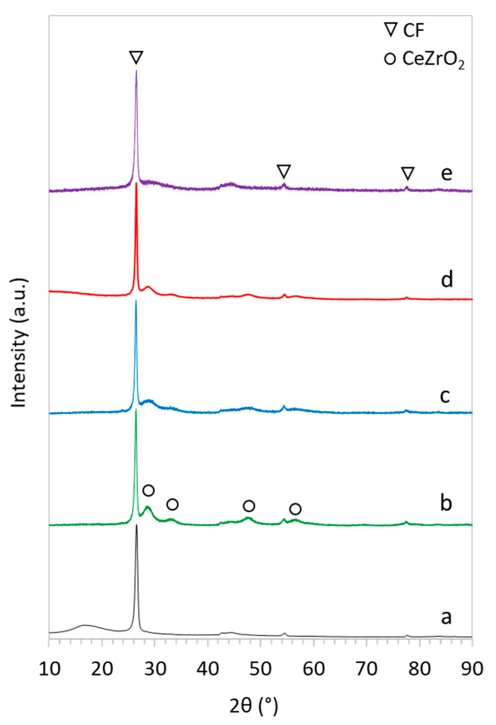
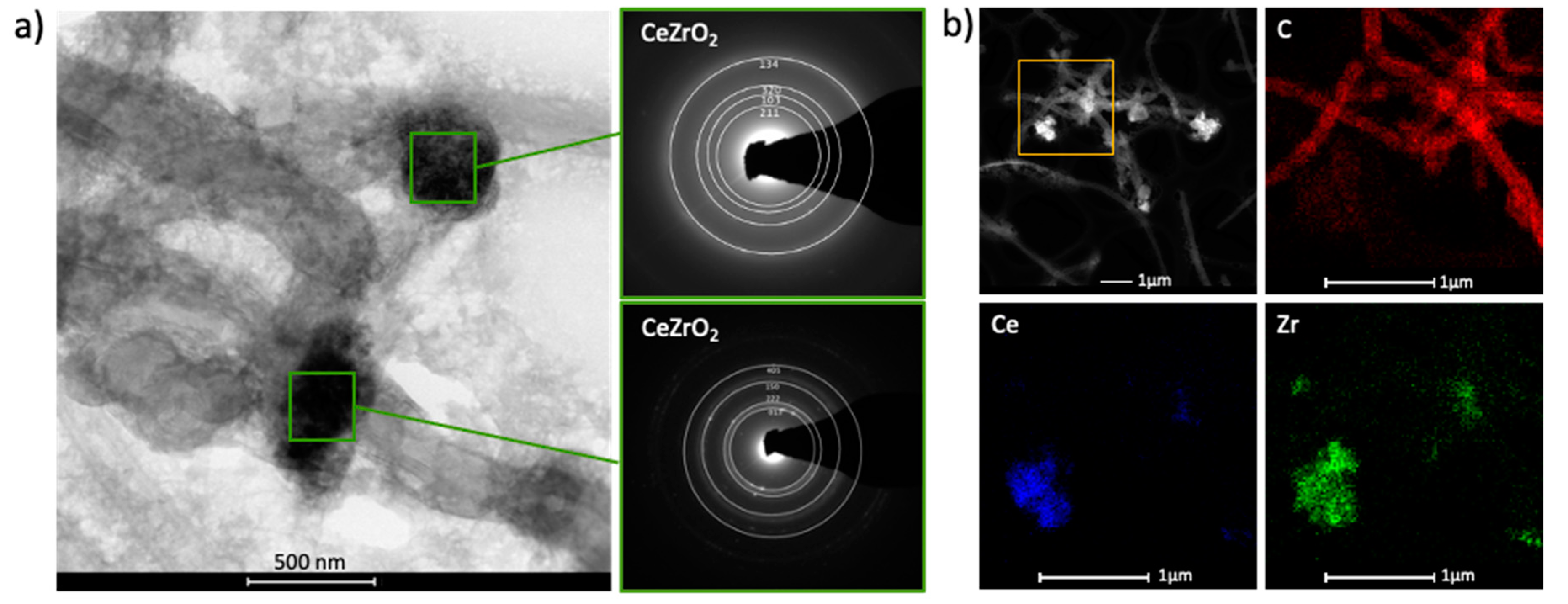
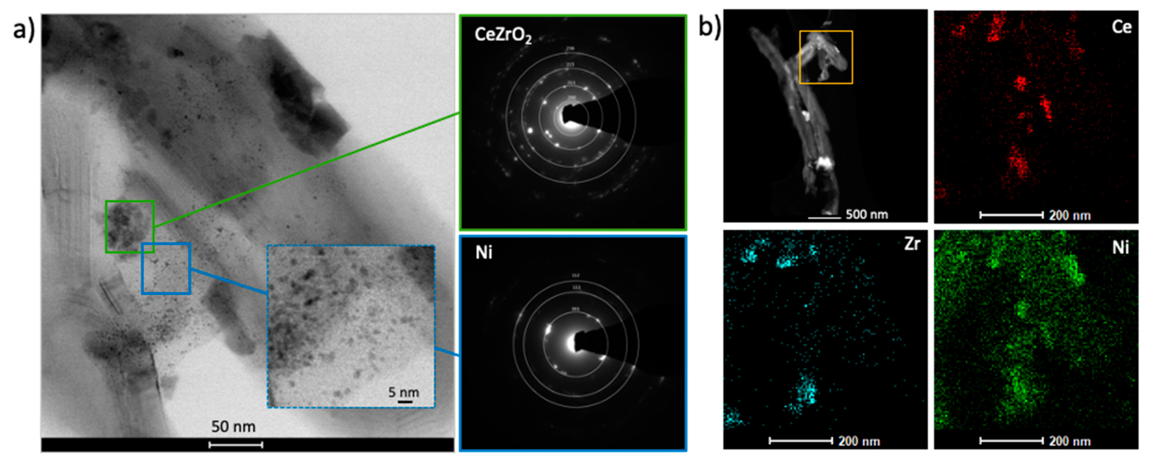
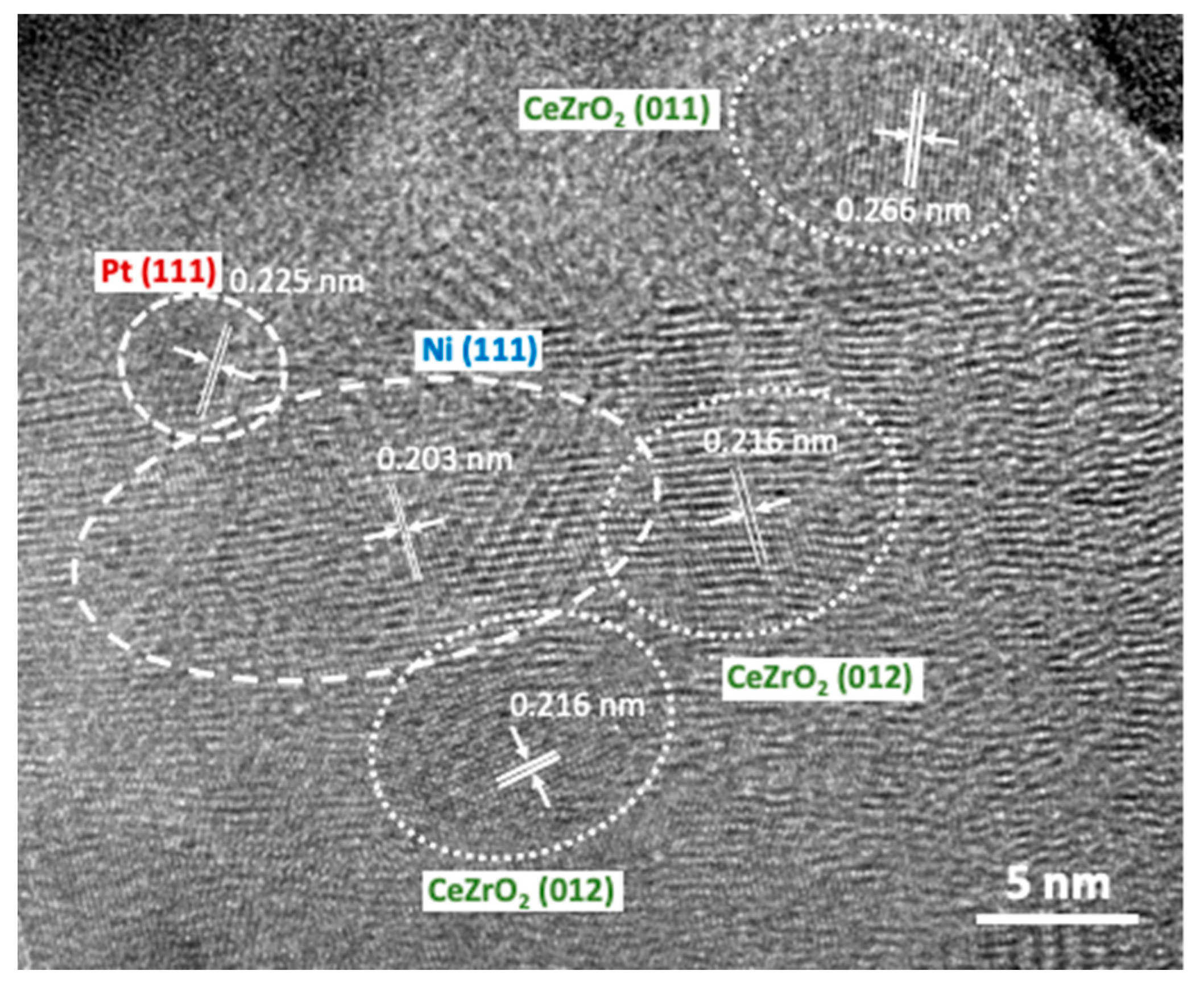
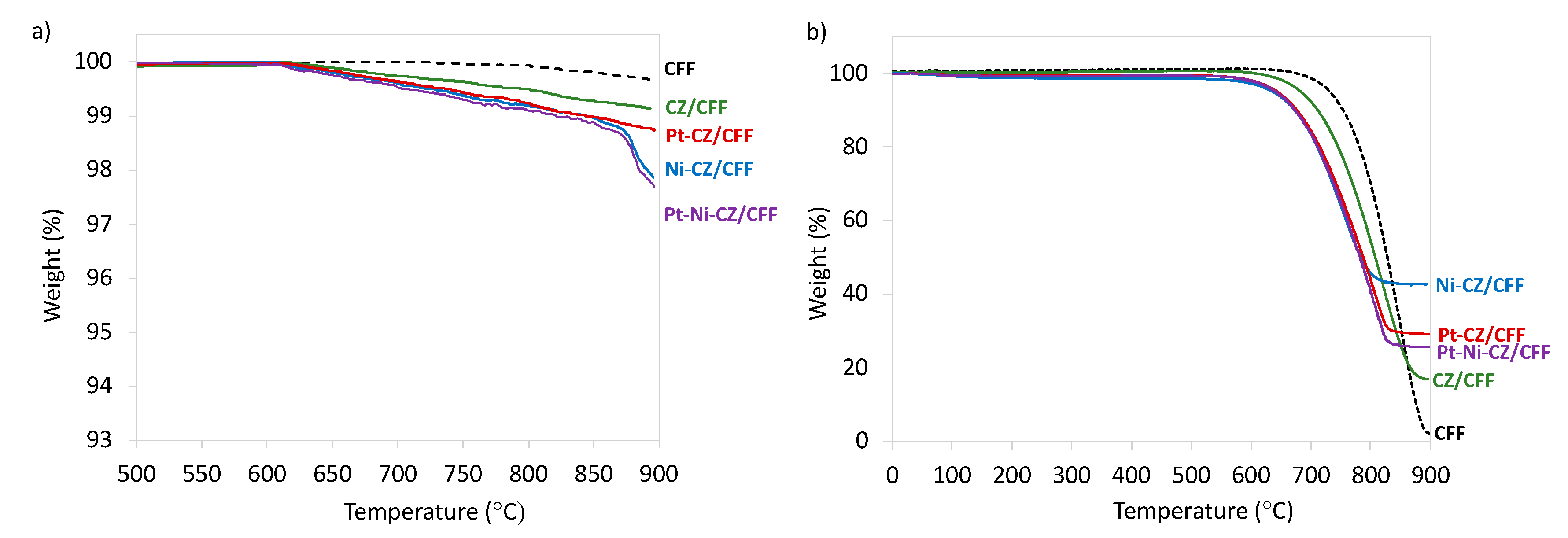
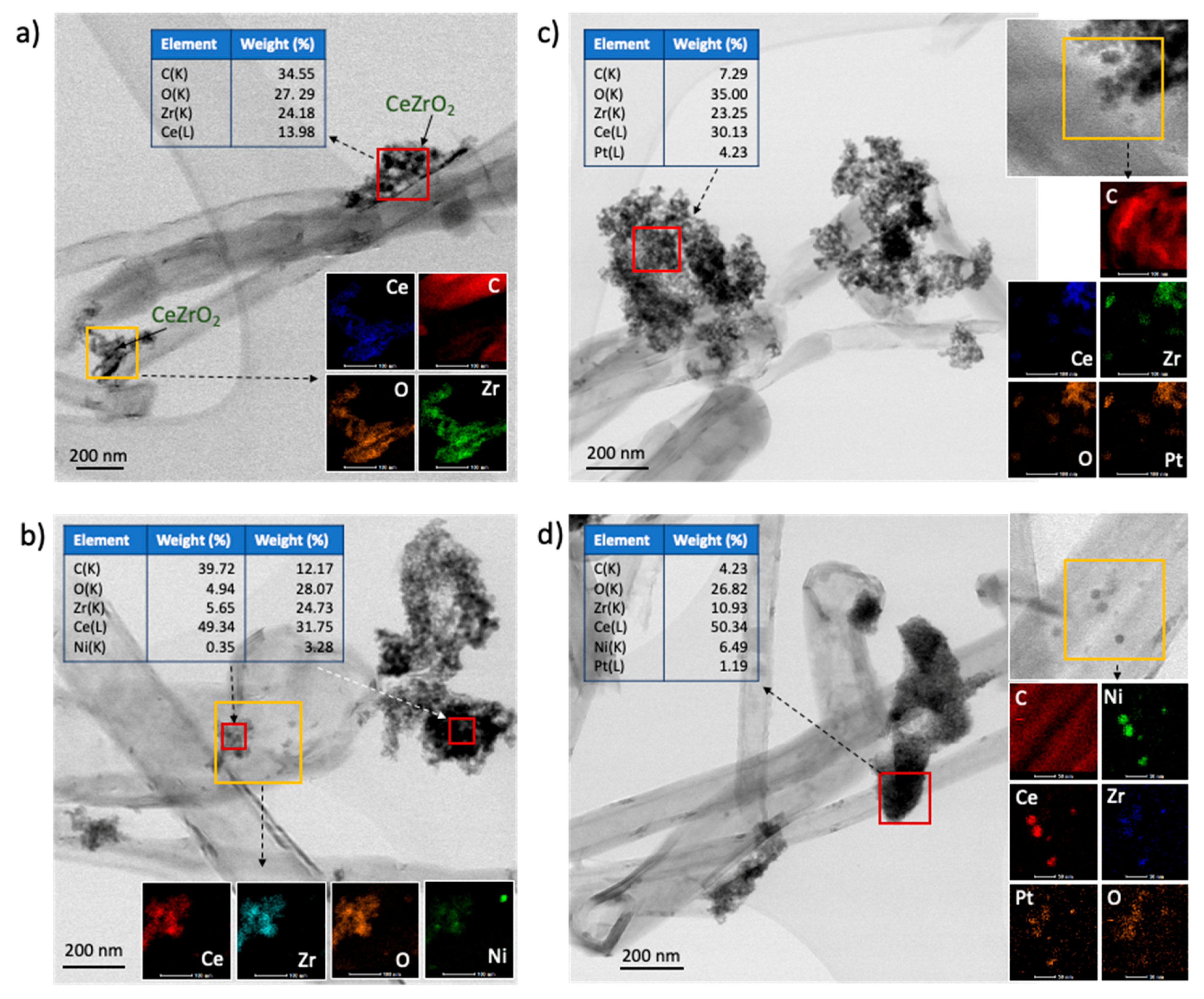
2.1. Catalyst Characterization

Four catalysts containing functionalised (via oxidation in HNO3) carbon fibres (CFF) and one, two or three of the following active phases: Ce0.61Zr0.39O2 (20 wt.%), Ni (1.6 wt.%) and Pt (0.16 wt.%), were obtained. The CFF-supported CeZrO2 (CZ/CFF), Ni-CeZrO2 (Ni-CZ/CFF), Pt-CeZrO2 (Pt-CZ/CFF) and Pt-Ni-CeZrO2 (Pt-Ni-CZ/CFF) were subjected to typical characterisation analyses that allowed determination of their composition, morphology, textural properties, and thermal stability.
The X-ray diffraction (XRD) was used for determining the crystallinity of the obtained samples and their qualitative composition. The diffractograms displayed in Figure 1 characterise with high intensity reflexion at 2θ = 26.5° and low intensity peaks at 42.7, 54.6 and 76.5°, all of which are assigned to carbon fibres (CF) and correspond to the (002), (100), (004) and (110) crystalline planes, respectively [70]. Diffractograms for all CFF-supported catalysts show reflexions at 2θ = 28.8, 33.6, 47.8 and 56.9° corresponding to (111), (200), (220) and (331) planes of typical cubic fluorite structure of CeO2 [71]. During synthesis, the smaller zirconium ions easily solute into the ceria lattice; therefore, the obtained crystal structure retains as cerium oxide. In addition, the XRD did not show a ZrOx diffraction peak, proving the same that there was no segregation between CeO2 and ZrO2 phases [72]. The sizes of CeZrO2 crystallites calculated from the Scherrer equation in (111), (200) and (220) directions are similar for all catalysts and range from 2.40 to 3.50 nm (Table 1). Owing to very low Ni and Pt loadings, no reflections of those phases are observed on diffractograms for Ni-CZ/CFF, Pt-CZ/CFF and Pt-Ni-CZ/CFF.
Scanning and transmission electron microscopy (SEM, TEM) were used for determining the morphologies of catalysts and detecting the active phases that were deposited over the CF support. Results of SEM and TEM observations are presented in Figure 2, Figure 3, Figure 4 and Figure 5, and in Figures S1 and S2. They show that carbon fibres used as catalytic support were 100–300 nm wide and over 10 μm long. It can be clearly seen that the active phases not only deposited directly on the carbon fibres but also formed bigger agglomerates that were in a looser contact with the support. The selected area electron diffraction (SAED), energy-dispersive spectroscopy (EDS) and elemental mapping allowed to determine the chemical composition of the phases supported on CFF, and the mutual contact between them. It can be seen form Figure 2 that the synthesis of CZ/CFF resulted in the formation of agglomerates of CeZrO2 nanoparticles that attached to the walls of carbon fibres. As was detected by TEM, in most those agglomerates were exceeding 300 nm in size. In the case of Ni-CZ/CFF, Pt-CZ/CFF and Pt-Ni-CZ/CFF catalysts, the formation of mixed ceria-zirconia oxide was also proved by SAED and elemental mapping (Figure 3, Figure 4 and Figure 5), whereas those agglomerates were usually of >50 nm in Ni-CZ/CFF and of >100 nm in Pt-containing samples.
The nanoparticles of nickel of 2–4 nm diameter were detected in Ni-CZ/CFF sample (Figure 3b). Some of them were present in the same area with CeZrO2 nanoparticles suggesting strong Ni-CeZrO2 contact, whereas the others were loosely dispersed over CFF in the regions where CeZrO2 was absent. Such a difference in the Ni surroundings may result in the performance of the catalyst in DRM. Moreover, those observations are different from what we had noticed when examining the Ni-CZ/CNT catalyst [20] in which Ni and CeZrO2 were located rather in the same areas over CNT support. It must also be mentioned here that in the case of Ni-CZ/CNT [20] the Ni loading was over 6 times higher than in presented in this work Ni-CZ/CFF. Thus, it can be concluded that Ni ions preferentially attach to the functional groups on the surface of oxidised carbon fibres than react with the Ce and Zr salts to form a Ni-CeZrO2, and this phenomenon is more pronounced at low Ni loadings.
In the case of Pt-Ni-CZ/CFF, nickel particles were also found outside the region where Pt and CeZrO2 were existing (Figure 5b). In contrary to nickel, Pt was more likely to be in proximity with ceria-zirconia in both Pt-CZ/CFF (Figure 4b) and Pt-Ni-CZ/CFF (Figure 5b). However, the high-resolution TEM (HRTEM) observations of Pt-Ni-CZ/CFF (Figure 6) showed the co-existence of all three phases, i.e., CeZrO2, Pt and Ni, in vicinity. Those phases were detected by the fast Fourier transform (FFT). Strong interaction between those phases, known as strong metal–support interaction (SMSI), may result in formation of bonding between them and has significant impact on catalyst activity by inhibiting or promoting chemisorption of reagents. The SMSI effect in CeO2-containing systems has been studied, e.g., by Matte et al. [73], Thill et al. [74] or Mao et al. [75]. As well as HRTEM, X-ray photoelectron spectroscopy (XPS) and X-ray adsorption spectroscopy (XAS) are often applied to study this phenomenon. Co-precipitation of Ni and Pt on a catalytic support can lead to formation of Pt–Ni alloy that are known for having excellent catalytic properties arising from their surface structure (developed surface area), reconfigurable electronic structure, and mechanical stability [76]. In our case, the existence of Pt–Ni alloy in the fresh Pt-Ni-CZ/CFF catalyst was not proved.
The specific surface area (SSA), total pore volume (Vt) and average pore diameter (d) of pristine carbon fibres (CF), oxidised carbon fibres (CFF) and CFF-supported catalysts are presented in Table 2. As was expected, the SSA of carbon fibres increased after their oxidation in HNO3 (from 26 m2/g for CF to 100 m2/g for CFF). Whereas deposition of the active phases over CFF resulted in partial coverage of its surface and blockage of pores, which decreased the SSA. The most important drop of SSA was observed for the material with the highest content of the active phase, i.e., Pt-Ni-CZ/CFF, whose BET surface area was 44 m2/g.
The catalysts obtained were also subjected to thermogravimetric analysis (TGA) that allowed to determine their thermal stability in inert and oxidizing atmosphere. Ceria, alone, and doped with zirconium, is well known for its ability to store and release oxygen. That is one of the main advantages of this material that makes it resistant to carbon formation taking place, e.g., in reforming reactions of hydrocarbons (including DRM reaction), and resulting in catalyst deactivation. Nevertheless, when ceria or ceria-zirconia is deposited on carbon supports, such as CNT or CF, it may cause damage to this support by oxidizing it with the oxygen that is released from the CeO2 lattice. Such phenomenon is even more likely to occur when metal nanoparticles are deposited in ceria vicinity. Strong interactions between ceria and metal nanoparticles (SMSI) allow electron transfer from metal to ceria (regardless to the morphology of the latter), and oxygen transfer from ceria to metal (requires the presence of nanostructured CeO2) [77]. Nevertheless, the charge transfer depends on the kind of metal NPs that is supported on CeO2 [74].
The TGA in flowing N2 (Figure 7a) revealed that carbon fibres (CFF) are stable up to 800 °C and show some insignificant mass decrease (0.4%) above this temperature, which is probably due to the presence of functional groups. The other materials were found less stable and some linear mass decrease was observed to take place from 620 °C. In addition, the Ni-CZ/CFF and Pt-Ni-CZ/CFF showed rapid mass decrease from 820 °C. The total mass decrease of 1.0, 1.4, 2.2 and 2.4% was observed for CZ/CFF, Pt-CZ/CFF, Ni-CZ/CFF and Pt-Ni-CZ/CFF. Since the observed mass loss is caused by the CFF oxidation with oxygen form CeZrO2, one can conclude that the presence of Pt and Ni (that were already found to be in good contact with ceria-zirconia) enhances the oxygen transfer in the ceria lattice and increased oxidation of carbon fibres. Anyhow, those results imply that CFF based CeZrO2 containing catalysts can be considered thermally stable at high temperatures in the inert atmosphere.
In the oxidizing medium, however, the stability of those catalysts is significantly reduced. As is presented in Figure 7b, the oxidation of CFF starts at 670 °C and takes place until 890 °C, where all carbon is combusted. The temperature of CFF oxidation in CZ/CFF, Pt-CZ/CFF, Ni-CZ/CFF and Pt-Ni-CZ/CFF catalysts is shifted towards lower values, i.e., 620, 590, 586, and 580 °C, respectively. Such a decrease of thermal stability of carbon fibres is caused by the presence of CeZrO2 that utilizes its lattice oxygen for C oxidation, which is followed with formation of oxygen vacancies. During TGA in flowing air, the oxygen vacancies in ceria-zirconia lattice are being replenished with gaseous oxygen, so the CFF oxidation is faster than in the case of TGA in flowing N2. Moreover, the presence of Ni and Pt enhances the adsorption of oxygen and its release from the ceria–zirconia lattice, which in consequence lowers the temperature of carbon oxidation.
Vayssilov et al. [77] showed that the oxygen transfer through the CeO2-Pt boundary takes place only when a nanoscale ceria is in a strong contact with Pt, whereas it does not exist on the ordered bulk CeO2. From the TGA we can assume that the obtained catalysts can work at operating temperatures up to ca. 580 °C in the presence of gaseous oxygen.

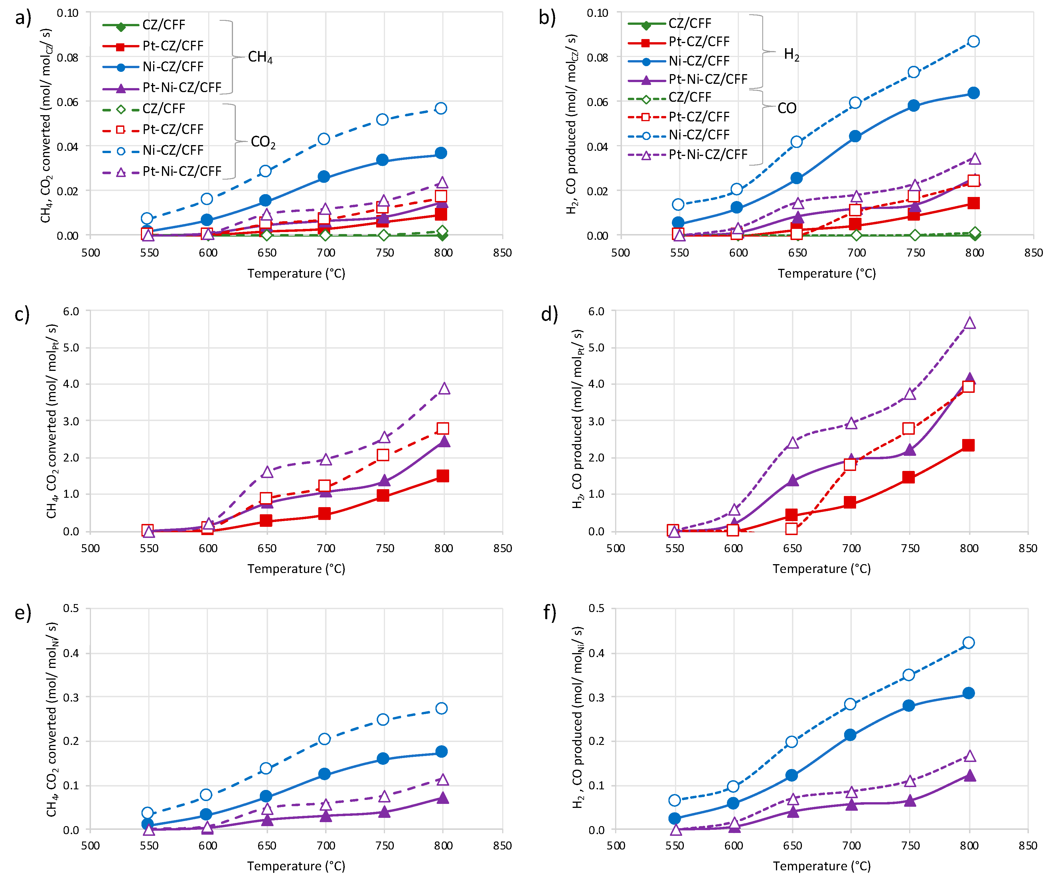
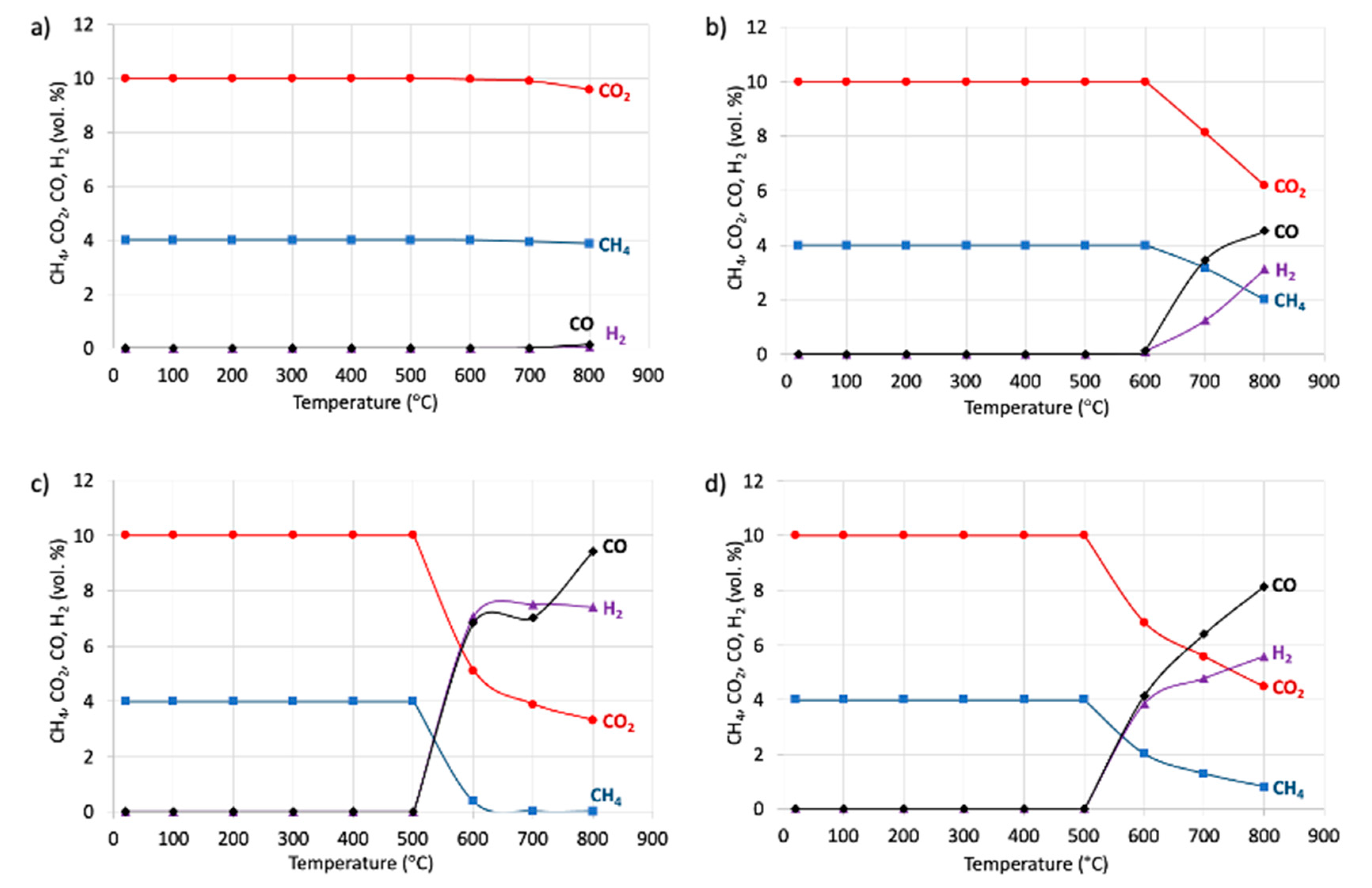
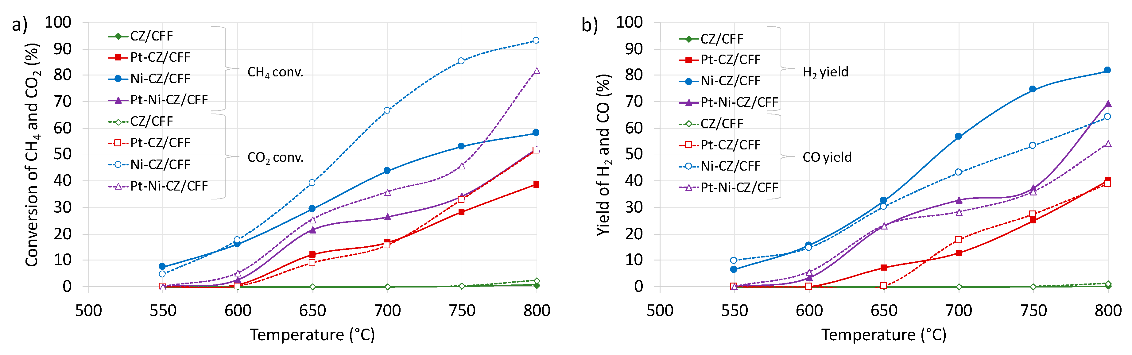
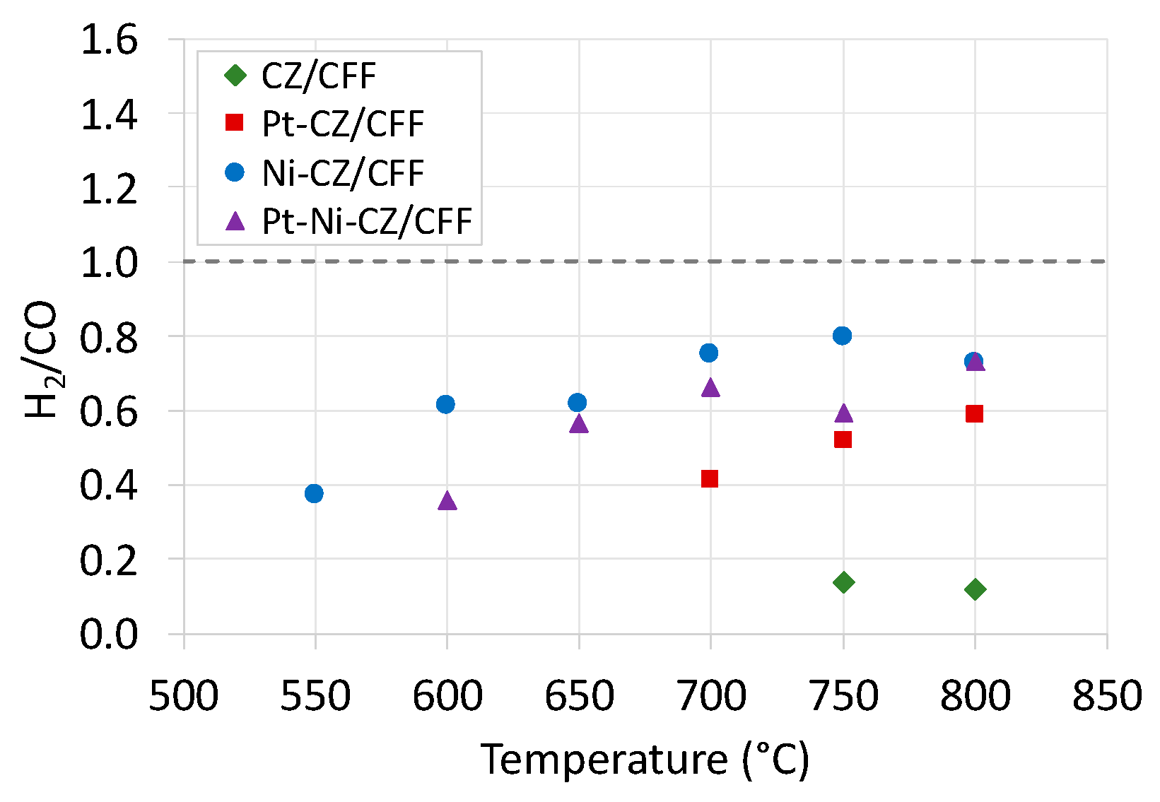
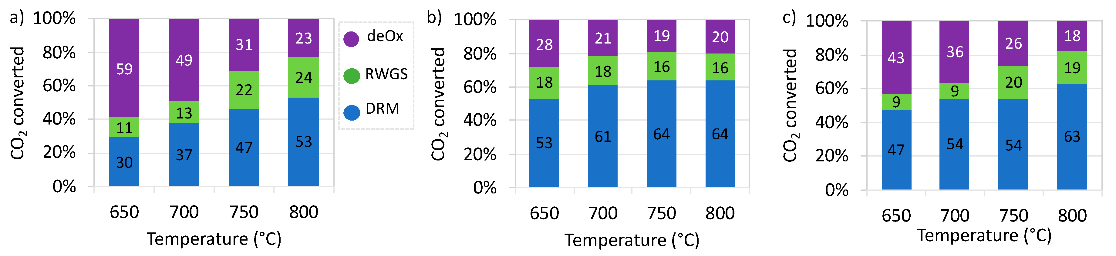
2.2. Catalytic Tests of Dry Reforming of Methane (DRM)

The performance of CFF-supported catalysts in DRM reaction was proved by tests in temperature-programmed (TP) conditions that allowed determination of temperature regions at which this reaction occurs, and in isothermal conditions to determine the conversion of CH4 and CO2, and the occurrence of parallel reactions.
It was revealed during TP tests (Figure 8) that CeZrO2 supported on carbon fibres exhibited negligible activity at temperature as high as 800 °C. However, introduction of only 0.16 wt.% of platinum to the system significantly improved conversions of CO2 and CH4. The Pt-CZ/CFF was found to be active in DRM above 600 °C. Even better results were observed for Ni-CZ/CFF catalyst over which the consumption of CH4 /CO2 and production of H2/CO started above 500 °C. In addition, a complete methane conversion was noticed at 620 °C. A rapid increase in CO formation above 700 °C, together with increased CO2 consumption and some decrease in H2 can evidence the occurrence of the reverse water gas shift (RWGS). The Pt-Ni-CZ/CFF catalyst showed the DRM activity in the same temperature region as Ni-CZ/CFF but its performance was worse, probably owing to predominant phase separation, i.e., Pt being in a good contact with CeZrO2 and Ni deposited alone on CFF.
The performance of CFF-supported catalysts in DRM during catalytic tests in isothermal conditions is presented in Figure 9. Carbon and hydrogen balance are shown in Table S1. The results obtained are consistent with the results of TP tests, i.e., the CZ/CFF revealed the lowest, negligible activity and Ni-CZ/CFF was the most active. The conversions of CH4 and CO2 over CZ/CFF after 2 h-on-stream at 800 °C were as low as 0.58% and 2.58%, respectively. Whereas CZ/CNT catalyst that was previously studied by us in DRM [20] and contained the same amount of CeZrO2 as reported in this work CZ/CFF, exhibited over 49% conversion of methane, which is drastically higher compared to CZ/CFF.
The difference in DRM performance between those two kinds of catalyst, i.e., deposited on CNT and CF, can be linked to the differences in the morphology and textural properties of those supports. Both the carbon nanotubes and carbon fibres are composed of graphene layers but they possess different dimensions. The CNT used as catalyst support in our previous work [20] had the inner diameter of 2–6 nm, the outer diameter of 6–13 nm and were 2.5–20 μm long; whereas the external diameter of carbon fibres used in this work was usually 200–300 nm and their length was exceeding 10 μm. According to this, carbon fibres, also after oxidation, have lower surface areas than their CNT-counterparts. The dispersion of the active phases over carbon fibres (this work) was not as good as over the CNT (presented in [20]); therefore, the contact of reagents with the active sites was reduced over the former and this naturally resulted in decreased catalytic activity.
Significant improvement of the CFF-supported CeZrO2 was observed after introduction of platinum—at 800 °C almost 40% conversion of CH4 was noticed for Pt-CZ/CFF. The Ni-CZ/CFF was found to be the most active among all catalysts and showed 58% of CH4 conversion whereas the Pt-Ni-CZ/CFF catalyst, that was expected to show superior performance compared to monometallic catalysts, was less active than Ni-CZ/CFF, and exhibited 52% CH4 conversion. The surface area of Pt-Ni-CZ/CFF was lower than for monometallic catalysts (Table 2). According to the Langmuir–Hinshelwood model which is most often used for DRM, both the CH4 and CO2 are adsorbed on the catalyst surface, and the rate-determining step is CH4 decomposition. Hence, the decrease in specific surface area, and thus reduced number of the active sites available for reagents, can explain the decrease in catalytic activity of the Pt-Ni-CZ/CFF. Moreover, according to microscopic observations (Figure 5) the co-precipitation resulted mostly in formation of two phases: Pt-CeZrO2 and Ni being separately deposited on carbon fibres. The co-existence of all three phases: Pt, Ni and CeZrO2, was minor (Figure 6), and HRTEM in those regions did not detect the presence of Pt–Ni alloy that has been known for its superior performance in DRM. Mahoney et al. [78] studied the Pt promoted Ni/CeZrO2 in the DRM reaction and observed that the introduction of platinum does not change significantly the CO2 conversion compared to Ni/CeZrO2 alone, but it improves the stability of the catalyst owing to the oxygen spill-over, and increases its catalytic activity in H2 production at moderate temperatures. The enhanced reducibility of the Pt-Ni/CeZrO2 and its improved catalytic performance arises from the Pt–Ni alloy formation. In our case, the formation of Pt–Ni alloy has not been proven which may explain the worse performance of the Pt-Ni-CZ/CFF in DRM compared to Ni-CZ/CFF. Araiza et al. [79] found that the catalytic activity of Ni/CeO2 was improved when Pt was added. They studied the DRM activity of Pt-Ni/CeO2 with different Pt:Ni atomic ratios obtained by the wetness incipient impregnation. Again, the key for the superior catalytic activity of the bimetallic catalyst was the formation of Pt–Ni alloy and enhanced contact between those two active metals. The results of the 8 h on-stream DRM tests over Ni-CZ/CFF and Pt-Ni-CZ/CFF were very similar to the results obtained after 2 h-on-stream. The CH4 conversions at 750 and 800 °C for Ni-CZ/CFF were 52 and 57%, while for Pt-Ni-CZ/CFF were 35% and 54%, respectively.
Figure 9 gives the general view on how the CFF-supported catalysts work in DRM, whereas to determine how the individual single active phases (i.e., CeZrO2, Pt and Ni) contribute to the catalyst activity, the rates of CH4 and CO2 conversions, and H2 and CO productions per mol of the active phase (AP) were calculated taking into consideration the molar fraction of each, single active phase (Equations (7)–(9)) and the obtained results were presented in Figure 10.
C i = F i   n A P   x j
P i = F i   n A P   x j
x j = n A P   n j  
where:
Ci—moles of reagent i (CH4, CO2) converted per 1 mole of the active site (mol/mol/s);
Pi—moles of reagent i (H2, CO) produced per 1 mole of the active site (mol/mol/s);
Fi—molar flow rate of reagent i (mol/s);
nAP—total number of moles of the active phase (AP), a sum of moles of CeZrO2, Ni and Pt (mol);
xj—molar fraction of the single active phase, where j is CeZrO2, Ni or Pt;
nj—moles of the single active phase, where j is CeZrO2, Ni or Pt (mol).
Figure 10. The comparison of the rates of CH4 and CO2 conversions (a,c,e), and H2 and CO productions (b,d,f) over CZ, Pt and Ni active sites in CFF-supported catalysts during DRM tests in isothermal conditions. Reaction mixture: 4 vol. % CH4, 10 vol. % CO2, balanced with Ar. GHSV = 5000 h−1. TOS = 2 h.
Catalysts 11 00563 g010
From Figure 10a,b it can be observed that the rates of CH4 and CO2 conversions, and H2 and CO productions increased when Pt was added to the catalyst, which was caused by the already mentioned SMSI effect occurring between CeZrO2 and Pt. The effect of Ni addition to Pt-CZ/CFF had a minor effect on reagents conversion/production over CeZrO2 and this can be linked to the fact that most of the nickel was deposited on CFF outside the Pt-CeZrO2 area. Conversely, the Ni-CZ/CFF showed the highest rates of CH4/ CO2 conversions over CeZrO2 because in this catalyst Ni was in better contact with CeZrO2. Similar trend is observed in Figure 10c,d showing somewhat higher rates of reagents conversions/productions over the Pt sites in the bimetallic Pt-Ni-CZ/CFF. But that increase, compared to Pt-CZ/CFF, can arise from the presence of a few areas of the occurrence of three phases together, i.e., Pt-Ni-CeZrO2. Examining the rates of CH4 and CO2 conversions, and H2 and CO productions over Ni (Figure 10e,f) one can observe that it was much higher in the Ni-CZ/CFF than in the bimetallic Pt-Ni-CZ/CFF. This is explained by the fact that in the former, a majority of Ni was in close contact with CeZrO2, unlike in the latter. Hence, the morphology of the Pt-Ni-CZ/CFF catalyst, especially regarding the distribution of individual active phases, that gives chances for creation of SMSI or disables it, is of great importance for its activity in DRM.
The H2/CO ratio at the reactor’s outlet (Figure 11) gives some information about the parallel reactions taking place during DRM. H2/CO exceeding 1, which a stoichiometric ratio for DRM, suggests carbon deposition as a result of two most common phenomena taking place on metallic active sites (*): CH4 decomposition (Equation (10)), or the Boudouard reaction (Equation (11)). However, in the presented cases the H2/CO was much lower than 1, and that evinces the occurrence of the reverse water gas shift reaction (RWGS) (Equation (12)). Furthermore, such a low H2/CO ratio can be caused by the occurrence of CO2 deoxidation “deOx” (Equation (13)), that produces CO and decreases the overall concentration of H2 in the product gas. This reaction is an elementary step in DRM and occurs on oxygen vacancies in CeZrO2 lattice and neighbouring Pt and Ni sites (* in Equation 13 denotes all of them). Usually, this reaction is an elementary step in DRM and delivers the oxygen to oxidize carbon species formed on the catalyst surface by methane dehydrogenation (Equation (10)). In our tests we used a DRM mixture containing CO2 in excess; therefore, it can be reduced beyond the DRM catalytic cycle and independently from the RWGS reaction.
CH4 + * ↔ C* + 2H2
2CO + * ↔ C* + CO2
CO2 + H2 ↔ CO + H2O
CO2 + * ↔ CO + *O
Figure 12 shows the contributions of three reactions that consume CO2 during DRM over CFF-supported Pt-CZ, Ni-CZ and Pt-Ni-CZ catalysts. The CZ/CFF was not taken into consideration because it showed minor activity in this reaction. In the case of Pt-CZ/CFF, the contribution of CO2 deoxidation was significantly higher than for Ni-CZ/CFF, and this can be explained by the very good deposition of Pt over CeZrO2, that allows the so called “reverse oxygen spillover”—a migration of oxygen from Ce4+ to Pt0 which results in PtO and increased concentration of Ce3+ ions that are the active sites for CO2 reduction. Moreover, the PtO was detected by XRD in the spent catalyst (denoted Pt-CZ/CFF(s)) (Figure 13c). For the Ni-CZ/CFF, the participation of DRM, RWGS and CO2 deoxidation was similar from 700 °C, with the most important contribution of DRM reaction. In this catalyst two “kinds” of Ni were present: first—being in a good contact with CeZrO2, and the second—deposited directly on CFF support. The contribution of DRM, RWGS and deOx over Pt-Ni-CZ/CFF at 800 °C was like that for Ni-CZ/CFF, whilst with lowering the temperatures the impact of the Pt-CeZrO2 became more important and the contribution of the reaction of CO2 deoxidation increased. Thanks to this reaction, the catalyst was supplied with active oxygen species that prevent carbon deposition followed by catalyst deactivation.
After DRM tests the catalysts were characterised with XRD, SEM/TEM and TGA (See the Supplementary Materials). The morphology of the catalysts changed to some extent after exposition to reaction conditions. First, the XRD for spent catalysts (Figure 13) showed the presence of the Ni phase, unlike in the case of fresh samples (Figure 1). The application of the Scherrer equation allowed to estimate the size of CeZrO2 and Ni crystallites in (220) and (111) directions, respectively (Table 3). Depending on the sample, from 50% to 57% increase in the size of the CeZrO2 crystallite after DRM was observed. Such an increase is usually a result of a catalyst’s exposition to high temperatures. Moreover, the microscopic observations (Figure 14d) revealed that in the spent bimetallic catalyst (Pt-Ni-CZ/CFF(s)) nickel occurred in the same areas as Pt and CeZrO2. Taking into consideration that in the fresh catalyst separation of Pt + CeZrO2 phase and Ni phase was observed, one can conclude that during catalyst exposition to DRM at high temperatures, Ni probably migrates to the places of Pt occurrence, forming the Pt–Ni alloy. To prove this, more detailed study on the evolution of the catalyst surface under DRM conditions is needed. The structure changes during DRM caused by Ni migration in the Pt–Ni bimetallic layers supported on alumina supports were observed by Gould et al. [80]. Under DRM reaction conditions (high temperature, presence of CH4 and CO2) and, at a certain Ni/Pt ratio in the catalyst, the Ni tended to increase its concentration at the surface of the Pt–Ni alloy owing to its strong driving force to diffuse into the Pt crystal.
One of the biggest problems during DRM is deactivation caused by carbon deposition. Although the carbon balance (Table S1) showed some (minor) carbon consumption, the TEM did not detect filamentous carbon deposits that often form during DRM. No CNT or other forms of carbon deposit were observed on the bright field TEM pictures depicted in Figure 14. Moreover, the thermogravimetric analysis-derivative thermogravimetry (TGA-DTG) analyses of Ni-CZ/CFF and Ni-Pt-CZ/CFF spent in the 8 h-on-stream catalytic tests at 750 and 800 °C (Figure 15) also did not prove the presence of carbon deposits. Therefore, we may assume that some insignificant amounts of coke might have formed on the catalysts. Regarding the carbon balance, one can also assume that carbon deposition on Ni-CZ/CFF was slightly higher than over Pt-Ni-CZ/CFF. As mentioned before, the formation of carbon deposits during DRM occurs mainly via methane decomposition (Equation (10)) and CO disproportionation (Equation (11)). The first reaction is structure-sensitive and can be inhibited by controlling the structure of the catalyst surface. The growth of filamentous carbon, e.g., nanotubes or nanofibers (CNF), is easier on large Ni particles.
It was calculated using density functional theory (DFT) simulations [81,82], that the terrace Ni(111) is a low-energy surface for producing carbon atoms from methane dehydrogenation. It is exposed to the CH4 molecules and allows easy migration of the carbon atoms that can diffuse to the adjacent step sites and contribute to the growth of carbon nanotube. Whereas in the bimetallic Pt-Ni(111) catalyst the C–H dissociation barrier is higher than on pure Ni(111), so the former shows better coke resistance [83,84]. In addition, the incorporation of Pt to the catalyst stabilizes the size of Ni particles and prevents Ni from encapsulation in carbon. That phenomenon is a result of the anchoring of nickel particles by multiple carbon layers that grow in multiple directions. García-Diéguez et al. [85] reported that Pt addition to the Ni/Al2O3 catalyst inhibits global carbon formation, and the C formed in the bimetallic catalysts (Pt-Ni/Al2O3) seems to be less strongly bound to the Ni than in the monometallic Ni/Al2O3 catalyst. Moreover, unlike in the case of Ni, carbon does not diffuse on Pt particles but is gasified providing a constant-level activity of Pt sites. According to Niu et al. [86], in bimetallic catalysts a modification of the electronic structure of active sites takes place. It influences the adsorption of particular reagents. Specifically, it reduces the activation energy of CH4 dissociation and CO2 activation, compared to monometallic catalysts. Moreover, it enhances the reactivity of surface oxygen species which improves the suppression of carbon species. The DFT calculations showed that reduced carbon deposition on Pt–Ni compared to Ni arises from (i) higher energy barrier for decomposition of *CH species that result in *C (*CH = *C + *H), and (ii) lower energy barriers for oxidation of *CH species (*CH + *O = *CHO + *, where *CHO is an intermediate for CO) and *C species (*C + *O = *CO + *). Owing to this, the concentration of carbon on the surface of Pt–Ni is reduced. In addition, Pt–Ni weakens the hydrogen dissociation, thus decreases the RWGS and increases H2 production.
The surface orientation of Ni is also very important for the CO2 activation pathway. By using DFT calculations Cai et al. [87] determined that CO2 adsorption on Ni(111) (that was detected by HRTEM on the CeZrO2 surface in our work) results mostly in surface carbonates because chemisorbed CO2 easily reacts with surface oxygen, while on Ni(100) the major species are adsorbed CO* and graphitic carbon that are results of the successive C−O bond cleavage. In our study, neither the monometallic Ni nor the bimetallic Pt–Ni supported together with CeZrO2 on carbon fibres were deactivated during DRM owing to carbon deposition.

3. Materials and Methods

3.1. Catalyst Preparation

All catalysts were obtained using PAN-based carbon fibres (CF) as a support (Sigma Aldrich, Poznan, Poland, product No. 719781, purity > 98%, conical platelets). Prior to syntheses, the CF were oxidised in HNO3 (65%, Chempur, Warszawa, Poland) at 60 °C for 5 h with continuous mixing. Oxidised carbon fibres (CFF) were washed with distilled water until pH = 7, and dried at 120 °C for 12 h.
The active phases (CeZrO2, Pt and Ni) were deposited on CFF support via the simple co-precipitation method. The 0.5 g of CFF was suspended in 100 mL of acetone and placed in a three-necked round-bottom flask equipped with a reflux condenser. Preparation of the CZ/CFF: each of the salts, i.e., Ce(NO3)3·6H2O and N2O7Zr·xH2O (both purchased in Sigma Aldrich, Poznań, Poland), was dissolved in 10 mL of the 1:1 mixture of distilled water and acetone. Next, the solutions were simultaneously instilled in the CFF/acetone suspension under continuous stirring. The mixture was then sonicated for 35 min and an aqueous, 1M NaOH solution was instilled until pH = 10. Subsequently, the mixture was heated at 70 °C for 5 h, cooled down to room temperature, and left overnight under continuous stirring. The next day the product was filtered off under reduced pressure and washed with distilled water several times until pH = 7. Afterward, the obtained material was dried at 120 °C for 12 h, and then calcined at 500 °C for 2 h in flowing N2. Pt-CZ/CFF, Ni-CZ/CFF and Pt-Ni-CZ/CFF were obtained according to the same procedure described above, but the Pt precursors was aqueous solution of H2PtClO6 while Ni precursor was Ni(NO3)2·6H2O (both purchased in Sigma Aldrich, Poznan, Poland). In each synthesis the solutions of metal salts were being instilled to the CFF/acetone suspension simultaneously. The composition of prepared CFF-supported catalysts is presented in Table 4.

3.2. Catalyst Characterisation

The X-ray diffraction (XRD) measurements were performed using MiniFlex600 diffractometer (Rigaku, Tokyo, Japan) equipped in Cu Kα anticathode (λ = 1.54 Å) for 2θ ranging from 10 to 90° with steps of 0.01° and scanning rate of 1°/min.
The Brunauer–Emmet–Teller (BET) specific surface areas of catalysts were determined by the N2 adsorption/desorption at 77 K using the Autosorb 3.01 (Quantachrome Instruments, Boynton Beach, FL, USA). Before analyses, the samples were outgassed at 150 °C for 12 h. The average pore size and pore volume were calculated using the Barrett–Joyner–Halenda (BJH) method.
The TGA of the fresh catalysts were performed using thermogravimetric analysers (Mettler-Toledo, Columbus, OH, USA). The changes in catalysts weights were recorded both in flowing air and N2 at temperature being increased from 25 to 900 °C with a rate of 10 °C/min). The TG and DTG curves for spent catalysts were recorded in flowing air under heating from 25 to 900 °C with a rate of 10 °C/min, using the STA 449 F5 apparatus (Netzsch, Berlin, Germany).
The study on catalysts morphology was conducted using a S/TEM Titan 80–300 microscope (FEI Company, Hillsboro, UK) equipped with energy dispersive X-ray spectroscopy detector (EDAX EDS). An accelerating voltage of 300 kV was applied.

3.3. Catalytic Tests

Catalytic tests of the DRM reaction were carried out in a U-shaped, fixed bed, quartz reactor under atmospheric pressure. The reaction mixture was composed of CH4 (4 vol. %), CO2 (10 vol. %) and Ar as balance. The gas hourly space velocity (GHSV) was 5000 h−1. Catalytic tests were conducted in (i) temperature programmed conditions (TP), and (ii) isothermal conditions. During TP experiments the temperature in the reactor was increased from 25 to 800 °C with a rate of 10 °C/min. Next, the catalyst performance was being examined in isothermal conditions starting at 800 °C, and decreasing the temperature by 50 °C until 600 °C. The residence time at each temperature was 2 h. In addition, Ni-CZ/CFF and Pt-Ni-CZ/CFF catalysts were subjected to 8 h on-stream catalytic tests at 750 and 800 °C. The composition of the gas at the reactor’s outlet was determined using a gas chromatograph (GC) equipped with thermocouple detector (TCD). Before and after the catalytic test, the reactor with the catalyst sample was weighed in order to detect any changes in the mass of catalyst bed caused, e.g., by oxidation of CFF (mass decrease) or carbon deposition (mass increase).

4. Conclusions

Four DRM catalysts containing oxidised carbon fibres (CFF) and supported on it CeZrO2 with Ni, Pt or Pt + Ni were obtained. Those catalysts were characterised by using XRD, N2 sorption, SEM/TEM and TGA that allowed determination of their composition, morphology, textural properties, and thermal stability. The catalysts were also subjected to DRM tests that indicated that their activity decreased in the following order: Ni-CZ/CFF > Pt-Ni-CZ/CFF > Pt-CZ/CFF >> CZ/CFF, whereas the morphologies of those catalysts and the contact between deposited phases were the most important factors. Microscopic observations proved that in Pt-containing catalysts platinum tended to deposit on CFF in the proximity with CeZrO2, whereas nickel (in Ni-containing catalysts) was detected both in the areas of CeZrO2 occurrence and in the regions where CeZrO2 was absent. The HRTEM for Pt-Ni-CZ/CFF showed some areas where CeZrO2, Pt and Ni were in close vicinity, which suggested strong interaction between those phases and improved catalytic performance of such a system. Nevertheless, that catalyst did not show higher activity in DRM compared to Ni-CZ/CFF, which could be due to the absence of the Pt–Ni alloy, whose formation has significant impact on the superior CH4 and CO2 conversions and has been observed in various Pt + Ni-containing catalytic systems reported in the literature. Moreover, the Ni-CeZrO2 contact has also been found important for good DRM activity. According to the elemental mapping, in Pt-Ni-CZ/CFF, nickel in most was allocated over CFF alone, and to a lesser extent over the CeZrO2 whereas in the Ni-CZ/CFF nickel deposition in the vicinity of CeZrO2 was more important, which finally resulted in higher activity of this catalyst in the DRM. The morphology and the contact between active phases deposited on CFF was also found important for the mechanism of DRM and the occurrence of parallel reactions, such as RWGS or CO2 deoxidation. It was noticed that in Pt-CZ/CFF and Pt-Ni-CZ/CFF catalysts, owing to very good deposition of Pt over CeZrO2 that enhances the “reverse oxygen spillover”, the contribution of the reaction of CO2 deoxidation was higher than for Ni-CZ/CFF. This reaction supplies the active oxygen species to the catalyst inhibiting the same carbon deposition.
The CFF supported catalysts obtained in this work were found to be thermally stable up to 800 °C in inert atmosphere, and up to about 580 °C under flowing air. No change in the weight of the catalyst sample was observed after catalytic tests of DRM. Taking into consideration that SEM, TEM and TGA of spent catalysts did not evidence the presence of carbon deposits, one can conclude that CO2 that was present in excess in the DRM reaction mixture did not oxidize the carbon fibre support.
Carbon fibres supported Ni, Pt and Pt-Ni catalysts were found to be less active in DRM than reported in our previous work on CNT-based Ni and Ni-CeZrO2. It arises from the differences in morphology and textural properties of both carbon supports. Despite this, presented in this paper CFF-based catalysts are good candidates for CH4/CO2 conversion into syngas, especially taking into consideration the possibility of CF manufacturing from waste clothes, fabric, etc., which will make the DRM process even more sustainable. Moreover, it is important that obtained CFF-supported catalysts were resistant to carbon deposition (even after 8 h on-stream DRM) which was proved by SEM, TEM and TGA. However, the modification of the synthesis procedure for Pt-Ni-CeZrO2/CFF catalysts is required to improve the contact between Pt and Ni, and allow formation of Pt–Ni alloy for superior activity in DRM.

Supplementary Materials

The following are available online at https://www.mdpi.com/article/10.3390/catal11050563/s1, Figure S1: SEM pictures of CZ/CFF, Ni-CZ/CFF, Pt-CZ/CFF, and Pt-Ni-CZ/CFF before and after DRM reaction; Figure S2: TEM pictures of CZ/CFF, Ni-CZ/CFF, Pt-CZ/CFF, and Pt-Ni-CZ/CFF before and after DRM reaction. Table S1: Carbon and hydrogen balance (calculated from Equations (S1) and (S2)) during catalytic tests of DRM over CZ/CFF, Pt-CZ/CFF, Ni-CZ/CFF, and Pt-Ni-CZ/CFF catalysts. Reaction mixture: 4 vol. % CH4, 10 vol. % CO2, balanced with Ar. TOS = 2 h. GHSV = 5000 h−1; Table S2: Performance of various Ni and Pt-Ni catalysts supported on CeZrO2 and carbon supports.

Author Contributions

Conceptualization, A.Ł.; methodology, A.Ł.; investigation, P.J., A.Ł., K.M, M.S.; resources, A.Ł.; data curation, A.Ł., P.J., K.M.; writing—original draft preparation, P.J., A.Ł.; writing—review and editing, A.Ł.; supervision, A.Ł.; All authors have read and agreed to the published version of the manuscript.

Funding

This research received no external funding.

Data Availability Statement

Data is contained within the article or Supplementary Materials.

Acknowledgments

This work was financed by the Ministry of Science and Higher Education from the statutory activity subsidy for the Faculty of Chemistry of Wrocław University of Science and Technology.

Conflicts of Interest

The authors declare no conflict of interest.

References

  1. Zhang, Y.-J.; Da, Y.-B. The decomposition of energy-related carbon emission and its decoupling with economic growth in China. Renew. Sustain. Energy Rev. 2015, 41, 1255–1266. [Google Scholar] [CrossRef]
  2. Davis, S.J.; Caldeira, K.; Matthews, H.D. Future CO2 Emissions and Climate Change from Existing Energy Infrastructure. Science 2010, 329, 1330–1333. [Google Scholar] [CrossRef] [Green Version]
  3. Liu, D.; Guo, X.; Xiao, B. What causes growth of global greenhouse gas emissions? Evidence from 40 countries. Sci. Total Environ. 2019, 661, 750–766. [Google Scholar] [CrossRef]
  4. Royal Society (Great Britain); Royal Academy of Engineering (Great Britain). Greenhouse Gas Removal. 2018. Available online: https://www.raeng.org.uk/publications/reports/greenhouse-gas-removal (accessed on 28 April 2021).
  5. Zhao, Y.; Kang, Y.; Li, H.; Li, H. CO2 conversion to synthesis gas via DRM on the durable Al2O3/Ni/Al2O3 sandwich catalyst with high activity and stability. Green Chem. 2018, 20, 2781–2787. [Google Scholar] [CrossRef]
  6. Shagdar, E.; Lougou, B.G.; Shuai, Y.; Ganbold, E.; Chinonso, O.P.; Tan, H. Process analysis of solar steam reforming of methane for producing low-carbon hydrogen. RSC Adv. 2020, 10, 12582–12597. [Google Scholar] [CrossRef]
  7. Kikuchi, E.; Chen, Y. Syngas Formation by Partial Oxidation of Methane in Palladium Membrane Reactor. In Studies in Surface Science and Catalysis; Parmaliana, A., Sanfilippo, D., Frusteri, F., Vaccari, A., Arena, F., Eds.; Natural Gas Conversion V; Elsevier: Amsterdam, The Netherlands, 1998; Volume 119, pp. 441–446. [Google Scholar]
  8. Castro-Luna, A.E.; Iriarte, M.E. Carbon dioxide reforming of methane over a metal modified Ni-Al2O3 catalyst. Appl. Catal. Gen. 2008, 343, 10–15. [Google Scholar] [CrossRef]
  9. Nikoo, M.K.; Amin, N.A.S. Thermodynamic analysis of carbon dioxide reforming of methane in view of solid carbon formation. Fuel Process. Technol. 2011, 92, 678–691. [Google Scholar] [CrossRef] [Green Version]
  10. Annesini, M.C.; Piemonte, V.; Turchetti, L. Carbon formation in the steam reforming process: A thermodynamic analysis based on the elemental compositions. Chem. Eng. Trans. 2007, 11, 21–26. [Google Scholar]
  11. García-Diéguez, M.; Pieta, I.S.; Herrera, M.C.; Larrubia, M.A.; Malpartida, I.; Alemany, L.J. Transient study of the dry reforming of methane over Pt supported on different γ-Al2O3. Catal. Today 2010, 149, 380–387. [Google Scholar] [CrossRef]
  12. Rezaei, M.; Alavi, S.M.; Sahebdelfar, S.; Yan, Z.-F. Syngas Production by Methane Reforming with Carbon Dioxide on Noble Metal Catalysts. J. Nat. Gas Chem. 2006, 15, 327–334. [Google Scholar] [CrossRef]
  13. Gronchi, P.; Mazzocchia, C.; del Rosso, R. Carbon dioxide reaction with methane on La2O3 supported Rh catalysts. Energy Convers. Manag. 1995, 36, 605–608. [Google Scholar] [CrossRef]
  14. Xu, Y.; Du, X.; Li, J.; Wang, P.; Zhu, J.; Ge, F.; Zhou, J.; Song, M.; Zhu, W. A comparison of Al2O3 and SiO2 supported Ni-based catalysts in their performance for the dry reforming of methane. J. Fuel Chem. Technol. 2019, 47, 199–208. [Google Scholar] [CrossRef]
  15. Nguyen, H.M.; Pham, G.H.; Ran, R.; Vagnoni, R.; Pareek, V.; Liu, S. Dry reforming of methane over Co–Mo/Al2O3 catalyst under low microwave power irradiation. Catal. Sci. Technol. 2018, 8, 5315–5324. [Google Scholar] [CrossRef] [Green Version]
  16. Zuo, Z.; Liu, S.; Wang, Z.; Liu, C.; Huang, W.; Huang, J.; Liu, P. Dry Reforming of Methane on Single-Site Ni/MgO Catalysts: Importance of Site Confinement. ACS Catal. 2018, 8, 9821–9835. [Google Scholar] [CrossRef]
  17. Zhang, M.; Zhang, J.; Wu, Y.; Pan, J.; Zhang, Q.; Tan, Y.; Han, Y. Insight into the effects of the oxygen species over Ni/ZrO2 catalyst surface on methane reforming with carbon dioxide. Appl. Catal. B Environ. 2019, 244, 427–437. [Google Scholar] [CrossRef]
  18. Alotaibi, R.; Alenazey, F.; Alotaibi, F.; Wei, N.; Al-Fatesh, A.; Fakeeha, A. Ni catalysts with different promoters supported on zeolite for dry reforming of methane. Appl. Petrochem. Res. 2015, 5, 329–337. [Google Scholar] [CrossRef] [Green Version]
  19. Najfach, A.J.; Almquist, C.B.; Edelmann, R.E. Effect of Manganese and zeolite composition on zeolite-supported Ni-catalysts for dry reforming of methane. Catal. Today 2020. [Google Scholar] [CrossRef]
  20. Łamacz, A.; Jagódka, P.; Stawowy, M.; Matus, K. Dry Reforming of Methane over CNT-Supported CeZrO2, Ni and Ni-CeZrO2 Catalysts. Catalysts 2020, 10, 741. [Google Scholar] [CrossRef]
  21. Figueira, C.E.; Moreira, P.F.; Giudici, R.; Alves, R.M.B.; Schmal, M. Nanoparticles of Ce, Sr, Co in and out the multi-walled carbon nanotubes applied for dry reforming of methane. Appl. Catal. Gen. 2018, 550, 297–307. [Google Scholar] [CrossRef]
  22. Otsuka, K.; Ogihara, H.; Takenaka, S. Decomposition of methane over Ni catalysts supported on carbon fibers formed from different hydrocarbons. Carbon 2003, 41, 223–233. [Google Scholar] [CrossRef]
  23. Wang, H.; Han, J.; Bo, Z.; Qin, L.; Wang, Y.; Yu, F. Non-thermal plasma enhanced dry reforming of CH4 with CO2 over activated carbon supported Ni catalysts. Mol. Catal. 2019, 475, 110486. [Google Scholar] [CrossRef]
  24. Cai, X.; Hu, Y.H. Advances in catalytic conversion of methane and carbon dioxide to highly valuable products. Energy Sci. Eng. 2019, 7, 4–29. [Google Scholar] [CrossRef] [Green Version]
  25. Boldrin, P.; Ruiz-Trejo, E.; Mermelstein, J.; Menéndez, J.M.B.; Reina, T.R.; Brandon, N.P. Strategies for carbon and sulfur tolerant solid oxide fuel cell materials, incorporating lessons from heterogeneous catalysis. Chem. Rev. 2016, 116, 13633–13684. [Google Scholar] [CrossRef] [PubMed]
  26. Djinović, P.; Batista, J.; Pintar, A. Efficient catalytic abatement of greenhouse gases: Methane reforming with CO2 using a novel and thermally stable Rh–CeO2 catalyst. Int. J. Hydrog. Energy 2012, 37, 2699–2707. [Google Scholar] [CrossRef]
  27. Rostrupnielsen, J.R.; Hansen, J.H.B. CO2-Reforming of Methane over Transition Metals. J. Catal. 1993, 144, 38–49. [Google Scholar] [CrossRef]
  28. Singh, S.A.; Madras, G. Sonochemical synthesis of Pt, Ru doped TiO2 for methane reforming. Appl. Catal. Gen. 2016, 518, 102–114. [Google Scholar] [CrossRef]
  29. Li, D.; Nakagawa, Y.; Tomishige, K. Methane reforming to synthesis gas over Ni catalysts modified with noble metals. Appl. Catal. Gen. 2011, 408, 1–24. [Google Scholar] [CrossRef]
  30. Crisafulli, C.; Scirè, S.; Maggiore, R.; Minicò, S.; Galvagno, S. CO2 reforming of methane over Ni–Ru and Ni–Pd bimetallic catalysts. Catal. Lett. 1999, 59, 21–26. [Google Scholar] [CrossRef]
  31. Choi, J.-S.; Moon, K.-I.; Kim, Y.G.; Lee, J.S.; Kim, C.-H.; Trimm, D.L. Stable carbon dioxide reforming of methane over modified Ni/Al2O3 catalysts. Catal. Lett. 1998, 52, 43–47. [Google Scholar] [CrossRef]
  32. Yokota, S.; Okumura, K.; Niwa, M. Support Effect of Metal Oxide on Rh Catalysts in the CH4-CO2 Reforming Reaction. Catal. Lett. 2002, 84, 131–134. [Google Scholar] [CrossRef]
  33. Ferreira-Aparicio, P.; Guerrero-Ruiz, A.; Rodríguez-Ramos, I. Comparative study at low and medium reaction temperatures of syngas production by methane reforming with carbon dioxide over silica and alumina supported catalysts. Appl. Catal. Gen. 1998, 170, 177–187. [Google Scholar] [CrossRef]
  34. Soria, M.A.; Mateos-Pedrero, C.; Guerrero-Ruiz, A.; Rodríguez-Ramos, I. Thermodynamic and experimental study of combined dry and steam reforming of methane on Ru/ ZrO-LaO catalyst at low temperature. Int. J. Hydrogen. Energy 2011, 36, 15212–15220. [Google Scholar] [CrossRef]
  35. Kim, J.-H.; Suh, D.J.; Park, T.-J.; Kim, K.-L. Effect of metal particle size on coking during CO2 reforming of CH4 over Ni–alumina aerogel catalysts. Appl. Catal. A Gen. 2000, 197, 191–200. [Google Scholar] [CrossRef]
  36. Han, J.W.; Kim, C.; Park, J.S.; Lee, H. Highly Coke-Resistant Ni Nanoparticle Catalysts with Minimal Sintering in Dry Reforming of Methane. ChemSusChem 2014, 7, 451–456. [Google Scholar] [CrossRef]
  37. Han, J.W.; Park, J.S.; Choi, M.S.; Lee, H. Uncoupling the size and support effects of Ni catalysts for dry reforming of methane. Appl. Catal. B Environ. 2017, 203, 625–632. [Google Scholar] [CrossRef]
  38. Zhang, Q.; Zhang, T.; Shi, Y.; Zhao, B.; Wang, M.; Liu, Q.; Wang, J.; Long, K.; Duan, Y.; Ning, P. A sintering and carbon-resistant Ni-SBA-15 catalyst prepared by solid-state grinding method for dry reforming of methane. J. CO2 Util. 2017, 17, 10–19. [Google Scholar] [CrossRef]
  39. Aramouni, N.A.K.; Zeaiter, J.; Kwapinski, W.; Ahmad, M.N. Thermodynamic analysis of methane dry reforming: Effect of the catalyst particle size on carbon formation. Energy Convers. Manag. 2017, 150, 614–622. [Google Scholar] [CrossRef]
  40. Seo, H.O. Recent Scientific Progress on Developing Supported Ni Catalysts for Dry (CO2) Reforming of Methane. Catalysts 2018, 8, 110. [Google Scholar] [CrossRef] [Green Version]
  41. Abd Ghani, N.A.; Azapour, A.; Syed Muhammad, S.A.F.; Ramli, N.M.; Vo, D.-V.N.; Abdullah, B. Dry reforming of methane for syngas production over Ni–Co-supported Al2O3–MgO catalysts. Appl. Petrochem. Res. 2018, 8, 263–270. [Google Scholar] [CrossRef]
  42. Hu, Y.H.; Ruckenstein, E. Catalytic conversion of methane to synthesis gas by partial oxidation and CO2, reforming. ChemInform 2004, 35, 297–345. [Google Scholar] [CrossRef]
  43. Chein, R.-Y.; Fung, W.-Y. Syngas production via dry reforming of methane over CeO2 modified Ni/Al2O3 catalysts. Int. J. Hydrogen Energy 2019, 44, 14303–14315. [Google Scholar] [CrossRef]
  44. Liotta, L.F.; Macaluso, A.; Longo, A.; Pantaleo, G.; Martorana, A.; Deganello, G. Effects of redox treatments on the structural composition of a ceria–zirconia oxide for application in the three-way catalysis. Appl. Catal. Gen. 2003, 240, 295–307. [Google Scholar] [CrossRef]
  45. Kim, J.-R.; Lee, K.-Y.; Suh, M.-J.; Ihm, S.-K. Ceria–zirconia mixed oxide prepared by continuous hydrothermal synthesis in supercritical water as catalyst support. Catal. Today 2012, 185, 25–34. [Google Scholar] [CrossRef]
  46. Laosiripojana, N.; Assabumrungrat, S. Catalytic dry reforming of methane over high surface area ceria. Appl. Catal. B Environ. 2005, 60, 107–116. [Google Scholar] [CrossRef]
  47. Gutiérrez-Ortiz, J.I.; de Rivas, B.; López-Fonseca, R.; González-Velasco, J.R. Characterization of the catalytic properties of ceria-zirconia mixed oxides by temperature-programmed techniques. J. Therm. Anal. Calorim. 2005, 80, 225–228. [Google Scholar] [CrossRef]
  48. Li, C.; Tan, P.-J.; Li, X.-D.; Du, Y.-L.; Gao, Z.-H.; Huang, W. Effect of the addition of Ce and Zr on the structure and performances of Ni–Mo/CeZr–MgAl(O) catalysts for CH4–CO2 reforming. Fuel Process. Technol. 2015, 140, 39–45. [Google Scholar] [CrossRef]
  49. Wolfbeisser, A.; Sophiphun, O.; Bernardi, J.; Wittayakun, J.; Föttinger, K.; Rupprechter, G. Methane dry reforming over ceria-zirconia supported Ni catalysts. Catal. Today 2016, 277, 234–245. [Google Scholar] [CrossRef] [Green Version]
  50. Zhang, F.; Liu, Z.; Chen, X.; Rui, N.; Betancourt, L.E.; Lin, L.; Xu, W.; Sun, C.-J.; Abeykoon, A.M.M.; Rodriguez, J.A.; et al. The Effects of Zr-doping into Ceria for the Dry Reforming of Methane over Ni/CeZrO2 catalysts: In-situ Studies with XRD, XAFS and AP-XPS. ACS Catal. 2020, 10, 3274–3284. [Google Scholar] [CrossRef]
  51. Kambolis, A.; Matralis, H.; Trovarelli, A.; Papadopoulou, C. Ni/CeO2-ZrO2 catalysts for the dry reforming of methane. Appl. Catal. A 2010, 377, 16–26. [Google Scholar] [CrossRef]
  52. Wang, F.; Xu, L.; Yang, J.; Zhang, J.; Zhang, L.; Li, H.; Zhao, Y.; Li, H.X.; Wu, K.; Xu, G.Q.; et al. Enhanced catalytic performance of Ir catalysts supported on ceria-based solid solutions for methane dry reforming reaction. Catal. Today 2017, 281, 295–303. [Google Scholar] [CrossRef]
  53. Mesrar, F.; Kacimi, M.; Liotta, L.F.; Puleo, F.; Ziyad, M. Syngas production from dry reforming of methane over ni/perlite catalysts: Effect of zirconia and ceria impregnation. Int. J. Hydrog. Energy 2018, 43, 17142–17155. [Google Scholar] [CrossRef]
  54. Nguyen, T.G.H.; Tran, D.L.; Sakamoto, M.; Uchida, T.; Sasaki, K.; To, T.D.; Doan, D.C.T.; Dang, M.C.; Shiratori, Y. Ni-loaded (Ce,Zr)O2-δ-dispersed paper-structured catalyst for dry reforming of methane. Int. J. Hydrog. Energy 2018, 43, 4951–4960. [Google Scholar] [CrossRef]
  55. Chen, W.; Zhao, G.; Xue, Q.; Chen, L.; Lu, Y. High carbon-resistance Ni/CeAlO3-Al2O3 catalyst for CH4/CO2 reforming. Appl. Catal. B Eniviron. 2013, 136, 260–268. [Google Scholar] [CrossRef]
  56. Taufiq-Yap, Y.H.; Sudarno, U.R.; Zainal, Z. CeO2-SiO2 supported nickel catalysts for dry reforming of methane toward syngas production. Appl. Catal. A Gen. 2013, 468, 359–369. [Google Scholar] [CrossRef]
  57. Sepehri, S.; Rezaei, M. Ce promoting effect on the activity and coke formation of Ni catalysts supported on mesoporous nanocrystalline γ-Al2O3 in autothermal reforming of methane. Int. J. Hydrog. Energy 2017, 42, 11130–11138. [Google Scholar] [CrossRef]
  58. Smirnova, M.Y.; Bobin, A.S.; Pavlova, S.N.; Ishchenko, A.V.; Selivanova, A.V.; Kaichev, V.V.; Cherepanova, S.V.; Krieger, T.A.; Arapova, M.V.; Roger, A.-C.; et al. Methane dry reforming over Ni catalysts supported on Ce–Zr oxides prepared by a route involving supercritical fluids. Open Chem. 2017, 15, 412–425. [Google Scholar] [CrossRef]
  59. Le Saché, E.; Pastor-Pérez, L.; Watson, D.; Sepúlveda-Escribano, A.; Reina, T.R. Ni stabilised on inorganic complex structures: Superior catalysts for chemical CO2 recycling via dry reforming of methane. Appl. Catal. B Environ. 2018, 236, 458–465. [Google Scholar] [CrossRef]
  60. Ross, R.A.; Fairbridge, C.; MacCallum, J.R. Carbon fibres as supports for transition metal catalysts in hydrocarbon oxidation reactions. Carbon 1985, 23, 209–213. [Google Scholar] [CrossRef]
  61. Shiba, K.; Tagaya, M.; Samitsu, S.; Motozuka, S. Effective Surface Functionalization of Carbon Fibers for Fiber/Polymer Composites with Tailor-Made Interfaces. ChemPlusChem 2014, 79, 197–210. [Google Scholar] [CrossRef] [PubMed]
  62. Zhu, L.; Huang, B.; Wang, W.; Wei, Z.; Ye, D. Low-temperature SCR of NO with NH3 over CeO2 supported on modified activated carbon fibers. Catal. Commun. 2011, 12, 394–398. [Google Scholar] [CrossRef]
  63. Yao, Y.; Wang, L.; Sun, L.; Zhu, S.; Huang, Z.; Mao, Y.; Lu, W.; Chen, W. Efficient removal of dyes using heterogeneous Fenton catalysts based on activated carbon fibers with enhanced activity. Chem. Eng. Sci. 2013, 101, 424–431. [Google Scholar] [CrossRef]
  64. Yuan, R.; Guan, R.; Liu, P.; Zheng, J. Photocatalytic treatment of wastewater from paper mill by TiO2 loaded on activated carbon fibers. Colloids Surf. Physicochem. Eng. Asp. 2007, 293, 80–86. [Google Scholar] [CrossRef]
  65. Lin, C.-L.; Cheng, Y.-H.; Liu, Z.-S.; Chen, J.-Y. Metal catalysts supported on activated carbon fibers for removal of polycyclic aromatic hydrocarbons from incineration flue gas. J. Hazard. Mater. 2011, 197, 254–263. [Google Scholar] [CrossRef]
  66. Wang, L.; Yao, Y.; Sun, L.; Mao, Y.; Lu, W.; Huang, S.; Chen, W. Rapid removal of dyes under visible irradiation over activated carbon fibers supported Fe(III)–citrate at neutral pH. Sep. Purif. Technol. 2014, 122, 449–455. [Google Scholar] [CrossRef]
  67. Tien, P.D.; Satoh, T.; Miura, M.; Nomura, M. Continuous hydrogen evolution from cyclohexanes over platinum catalysts supported on activated carbon fibers. Fuel Process. Technol. 2008, 89, 415–418. [Google Scholar] [CrossRef]
  68. Bulushev, D.A.; Yuranov, I.; Suvorova, E.I.; Buffat, P.A.; Kiwi-Minsker, L. Highly dispersed gold on activated carbon fibers for low-temperature CO oxidation. J. Catal. 2004, 224, 8–17. [Google Scholar] [CrossRef] [Green Version]
  69. Khan, A.; Jagdale, P.; Castellino, M.; Rovere, M.; Jehangir, Q.; Mandracci, P.; Rosso, C.; Tagliaferro, A. Innovative functionalized carbon fibers from waste: How to enhance polymer composites properties. Compos. B Part Eng. 2018, 139, 31–39. [Google Scholar] [CrossRef]
  70. Dobiášová, L.; Starý, V.; Glogar, P.; Valvoda, V. Analysis of carbon fibers and carbon composites by asymmetric X-ray diffraction technique. Carbon 1999, 37, 421–425. [Google Scholar] [CrossRef]
  71. Li, J.; Liu, X.; Zhan, W.; Guo, Y.; Guo, Y.; Lu, G. Preparation of high oxygen storage capacity and thermally stable ceria–zirconia solid solution. Catal. Sci. Technol. 2016, 6, 897–907. [Google Scholar] [CrossRef] [Green Version]
  72. Shao, S.; Shi, A.-W.; Liu, C.-L.; Yang, R.-Z.; Dong, W.-S. Hydrogen production from steam reforming of glycerol over Ni/CeZrO2 catalysts. Fuel Process Technol. 2014, 125, 1–7. [Google Scholar] [CrossRef]
  73. Matte, L.P.; Kilian, A.S.; Luza, L.; Alves, M.C.; Morais, J.; Baptista, D.L.; Dupont, J.; Bernardi, F. Influence of the CeO2 Support on the Reduction Properties of Cu/CeO2 and Ni/CeO2 Nanoparticles. J. Phys. Chem. C 2015, 119, 26459–26470. [Google Scholar] [CrossRef]
  74. Thill, A.S.; Kilian, A.S.; Bernardi, F. Key Role Played by Metallic Nanoparticles on the Ceria Reduction. J. Phys. Chem. C 2017, 121, 25323–25332. [Google Scholar] [CrossRef]
  75. Mao, M.; Zhang, Q.; Yang, Y.; Li, Y.; Huang, H.; Jiang, Z.; Hu, Q.; Zhao, X. Solar-light-driven CO reduction by methane on Pt nanocrystals partially embedded in mesoporous CeO2 nanorods with high light-to-fuel efficiency. Green Chem. 2018, 20, 2857–2869. [Google Scholar] [CrossRef]
  76. Zhou, L.; Luo, X.; Xu, L.; Wan, C.; Ye, M. Pt-Ni Nanoalloys for H2 Generation from Hydrous Hydrazine. Catalysts 2020, 10, 930. [Google Scholar] [CrossRef]
  77. Vayssilov, G.N.; Lykhach, Y.; Migani, A.; Staudt, T.; Petrova, G.P.; Tsud, N.; Skála, T.; Matolı’n, V.; Neyman, K.M.; Libuda, J. Support nanostructure boosts oxygen transfer to catalytically active platinum nanoparticles. Nat. Mater. 2011, 10, 310–315. [Google Scholar] [CrossRef]
  78. Mahoney, E.G.; Pusel, J.M.; Stagg-Williams, S.M.; Faraji, S. The effects of Pt addition to supported Ni catalysts on dry (CO2) reforming of methane to syngas. J. CO2 Util. 2014, 6, 40–44. [Google Scholar] [CrossRef]
  79. Araiza, D.G.; Arcos, D.G.; Gómez-Cortés, A.; Díaz, G. Dry reforming of methane over Pt-Ni/CeO2 catalysts: Effect of the metal composition on the stability. Catal. Today 2021, 360, 46–54. [Google Scholar] [CrossRef]
  80. Gould, T.D.; Montemore, M.M.; Lubers, A.M.; Ellis, L.D.; Weimer, A.W.; Falconer, J.L.; Medlin, J.W. Enhanced dry reforming of methane on Ni and Ni-Pt catalysts synthesized by atomic layer deposition. Appl. Catal. A Gen. 2015, 492, 107–116. [Google Scholar] [CrossRef] [Green Version]
  81. Li, J.; Croiset, E.; Ricardez-Sandoval, L. Methane dissociation on Ni (100), Ni (111), and Ni (553): A comparative density functional theory study. J. Mol. Catal. A Chem. 2012, 365, 103–114. [Google Scholar] [CrossRef]
  82. Liang, W.; Yan, H.; Chen, C.; Lin, D.; Tan, K.; Feng, X.; Liu, Y.; Chen, X.; Yang, C.; Shan, H. Revealing the Effect of Nickel Particle Size on Carbon Formation Type in the Methane Decomposition Reaction. Catalysts 2020, 10, 890. [Google Scholar] [CrossRef]
  83. Niu, J.; Ran, J.; Du, X.; Qi, W.; Zhang, P.; Yang, L. Effect of Pt addition on resistance to carbon formation of Ni catalysts in methane dehydrogenation over Pt-Ni bimetallic surfaces: A density functional theory study. Mol. Catal. 2017, 434, 206–218. [Google Scholar] [CrossRef]
  84. Fan, C.; Zhu, Y.-A.; Xu, Y.; Zhou, Y.; Zhou, X.-G.; Chen, D. Origin of synergistic effect over Ni-based bimetallic surfaces: A density functional theory study. J. Chem. Phys. 2012, 137, 014703. [Google Scholar] [CrossRef] [PubMed]
  85. García-Diéguez, M.; Pieta, I.S.; Herrera, M.C.; Larrubia, M.A.; Alemany, L.J. Nanostructured Pt- and Ni-based catalysts for CO2-reforming of methane. J. Catal. 2010, 270, 136–145. [Google Scholar] [CrossRef]
  86. Niu, J.; Wang, Y.; Liland, S.E.; Regli, S.K.; Yang, J.; Rout, K.R.; Luo, J.; Rønning, M.; Ran, J.; Chen, D. Unraveling Enhanced Activity, Selectivity, and Coke Resistance of Pt–Ni Bimetallic Clusters in Dry Reforming. ACS Catal. 2021, 11, 2398–2411. [Google Scholar] [CrossRef]
  87. Cai, J.; Han, Y.; Chen, S.; Crumlin, E.J.; Yang, B.; Li, Y.; Liu, Z. CO2 Activation on Ni(111) and Ni(100) Surfaces in the Presence of H2O: An Ambient-Pressure X-ray Photoelectron Spectroscopy Study. J. Phys. Chem. C 2019, 123, 12176–12182. [Google Scholar] [CrossRef]
Figure 1. X-ray diffraction (XRD) patterns of CFF (a), CZ/CFF (b), Ni-CZ/CFF (c), Pt-CZ/CFF (d), and Pt-Ni-CZ/CFF (e).
Catalysts 11 00563 g001
Figure 2. Bright field transmission electron microscopy (TEM) with selected area electron diffraction (SAED) (a) and elemental mapping for C, Ce and Zr (b) in CZ/CFF sample.
Catalysts 11 00563 g002
Figure 3. Bright field TEM with SAED (a) and elemental mapping for C, Ce, Zr and Ni (b) for Ni-CZ/CFF.
Catalysts 11 00563 g003
Figure 4. Bright field TEM with SAED (a) and elemental mapping for C, Ce, Zr and Pt (b) for Pt-CZ/CFF.
Catalysts 11 00563 g004
Figure 5. Bright field TEM with SAED (a) and Ce, Zr, Ni, Pt (b) for Pt-Ni-CZ/CFF.
Catalysts 11 00563 g005
Figure 6. High-resolution TEM (HRTEM) of Pt-Ni-CZ/CFF sample.
Catalysts 11 00563 g006
Figure 7. Thermogravimetric analysis (TGA) in N2 (a) and air (b) for CFF (black), CZ/CFF (green), Pt-CZ/CFF (red), Ni-CZ/CFF (blue) and Pt-Ni-CZ/CFF (purple).
Catalysts 11 00563 g007
Figure 8. The evolution of CH4 (blue), CO2 (red), H2 (purple) and CO (black) during dry reforming of methane (DRM) catalytic tests in temperature-programmed (TP) mode over CZ/CFF (a), Pt-CZ/CFF (b), Ni-CZ/CFF (c), and Pt-Ni-CZ/CFF (d) catalysts. Reaction mixture: 4 vol. % CH4, 10 vol. % CO2, balanced with Ar. Gas Hourly Space Velocity (GHSV) = 5000 h−1.
Catalysts 11 00563 g008
Figure 9. The conversions (conv.) of CH4 and CO2 (a), and yields of H2 and CO (b) over CZ/CFF, Pt-CZ/CFF, Ni-CZ/CFF, and Pt-Ni-CZ/CFF during catalytic test of DRM in isothermal conditions. Reaction mixture: 4 vol. % CH4, 10 vol. % CO2, balanced with Ar. GHSV = 5000 h−1. Time-on-stream (TOS) = 2 h.
Catalysts 11 00563 g009
Figure 11. The H2/CO ratio during DRM over CZ/CFF, Pt-CZ/CFF, Ni-CZ/CFF and Pt-Ni-CZ/CFF. Reaction mixture: 4 vol. % CH4, 10 vol. % CO2, balanced with Ar. GHSV = 5000 h−1. TOS = 2 h.
Catalysts 11 00563 g011
Figure 12. Contribution of DRM, reverse water-gas shift (RWGS) and CO2 deoxidation (deOx) in CO2 conversion during catalytic tests of DRM in isothermal conditions over Pt-CZ/CFF (a), Ni-CZ/CFF (b) and Pt-Ni-CZ/CFF (c). Reaction mixture: 4 vol. % CH4, 10 vol. % CO2, balanced with Ar. GHSV = 5000 h−1. TOS = 2 h.
Catalysts 11 00563 g012
Figure 13. X-ray diffraction (XRD) patterns of spent catalysts denoted CZ/CFF(s), Ni-CZ/CFF(s), Pt-CZ/CFF(s) and Pt-Ni-CZ/CFF(s).
Catalysts 11 00563 g013
Figure 14. Bright field TEM after DRM: CZ/CFF(s) (a), Pt-CZ/CFF(s) (b), Ni-CZ/CFF(s) (c) and Pt-Ni-CZ/CFF(s) (d). Red squares designate the areas of the energy-dispersive spectroscopy (EDS) analyses (results showing catalyst composition are shown in tables). The elemental mapping was performed for the yellow-square areas.
Catalysts 11 00563 g014
Figure 15. TGA and DTG for Ni-CZ/CFF and Pt-Ni-CZ/CFF catalysts spent in 8 h tests of DRM at 750 and 800 °C.
Catalysts 11 00563 g015
Table 1. The crystallite size (D) for CeZrO2 in (111), (200) and (220) direction.
SampleD111 (nm)D200 (nm)D220 (nm)
CZ/CFF3.502.433.18
Ni-CZ/CFF3.422.483.20
Pt-CZ/CFF3.402.463.22
Pt-Ni-CZ/CFF3.372.403.40
Table 2. Textural properties of CFF supported CeZrO2, Ni-CeZrO2, Pt-CeZrO2, Pt-Ni-CeZrO2 catalysts.
SampleSSA (m2/g)Vt (cc/g)d (nm)
CF (pristine)260.103.0
CFF1000.173.7
CZ/CFF690.233.9
Ni-CZ/CFF510.251.9
Pt-CZ/CFF520.123.7
Pt-Ni-CZ/CFF440.152.5
Table 3. The crystallite size (D) for CeZrO2 (220) and Ni(111) in spent catalysts.
SampleD (nm)
CeZrO2 (220)
D (nm)
Ni (111)
CZ/CFF(s)4.99-
Ni-CZ/CFF(s)4.839.87
Pt-CZ/CFF(s)4.99-
Pt-Ni-CZ/CFF(s)5.347.35
Table 4. The composition of prepared CFF-supported catalysts.
SampleCeZrO2 (wt. %)Ni
(wt. %)
Pt
(wt. %)
CF (pristine)---
CFF---
CZ/CFF20--
Ni-CZ/CFF201.6-
Pt-CZ/CFF20-0.16
Pt-Ni-CZ/CFF201.60.16
Publisher’s Note: MDPI stays neutral with regard to jurisdictional claims in published maps and institutional affiliations.

