Abstract
Advanced biofuels are required to facilitate the energy transition away from fossil fuels and lower the accompanied CO2 emissions. Particularly, jet fuel needs a renewable substitute, for which novel production routes and technology are needed that are more efficient and economically viable. The direct conversion of bio-syngas into fuel is one such development that could improve the efficiency of biomass for jet fuel processes. In this work, bifunctional catalysts based on hierarchical zeolites are prepared, tested and evaluated for their potential use in the production of actual jet fuel. The bifunctional catalysts Co/H-mesoZSM-5, Co/H-mesoBETA and Co/H-mesoY have been applied, and their performance is compared with their microporous zeolite-based counterparts and two conventional Fischer–Tropsch Co catalysts. Co/H-mesoZSM-5 and Co/H-mesoBETA showed great potential for the direct production of jet fuel as bifunctional catalysts. Besides the high jet fuel yields under Fischer–Tropsch synthesis conditions at, respectively, 30.4% and 41.0%, the product also contained the high branched/linear hydrocarbon ratio desired to reach jet fuel specifications. This reveals the great potential for the direct conversion of syngas into jet fuel using catalysts that can be prepared in few steps from commercially available materials.
1. Introduction
The energy transition is on everyone’s agenda, as made clear by the latest COP26 meeting in Glasgow [1]. This transition involves in large part electrification, because electricity can be obtained via renewable resources, such as solar, wind and hydro. However, the production capacity is not sufficient (yet) to supply all energy/heat demands and replace fossil fuels. Other energy resources, such as biomass, are required to cover the energy demand and facilitate the transition from fossil fuels. The deployment of bioenergy is expected to reach 100 to 300 EJ/y by 2050, which is a substantial contribution to the world’s primary energy demand [2]. This is especially meaningful in sectors where liquid fuels are required that cannot be substituted by other energy forms in the short to medium term. This is true, for instance, in aviation, where sustainable aviation fuels (SAF) in the form of advanced biofuels can achieve a 75% reduction in CO2 emissions [3]. In the EU, the European advanced biofuels flightpath action was set out to spur the commercial development to produce SAF (2 million tons by 2020), in which >1000 ton of Fischer–Tropsch biofuels would become available [4].
Syngas (CO, H2 and CO2 mixtures) production and conversion can provide routes for the production of renewable synthetic fuels when the syngas is produced in a sustainable manner. This includes, for example, the conversion of biomass/bio-residues via gasification or reforming. Novel technologies for syngas production and conversion are being studied for implementation. An example is the residual bioglycerol conversion using sorption-assisted, chemical-looping recycling (SA-CLR), part of the EU Horizon 2020 GLAMOUR research project [5]. In this GLAMOUR process, the syngas is converted to transportation fuels using Fischer–Tropsch synthesis (FTS), specifically the Co-catalyzed low temperature Fischer–Tropsch (LTFT).
Conventionally, the strategy in LTFT is to produce hydrocarbons high in wax that are subsequently hydrocracked to a middle distillate fraction that contains up to 50% kerosene [6]. The technology is employed on an industrial scale, but it is based on gas from fossil fuels (natural gas/coal) [7]. New technologies and catalytic development are required to match the scale of biomass conversion, including the direct conversion of syngas into jet fuel. The advantages of a one-step conversion of syngas into jet fuel include the higher yield. Moreover, no additional hydrocracking would be required, nor would there be need to produce pure hydrogen at high pressures. Additionally, the mass transfer in the catalyst bed can be improved due to the absence of liquid wax.
Co catalysts supported on hierarchical zeolites have been successfully applied as bifunctional (bif.) catalysts in the direct synthesis of liquid fuels from syngas without the formation of wax [8,9,10,11]. A key improvement was brought about by the introduction of the hierarchical zeolites, which contain both micro- and mesopores, simply referred to as mesoporous zeolites. The hierarchical structure was found to be crucial for the high selectivity to liquids of the improved mass transfer as compared to microporous zeolites [8]. Further improvements, especially in creating jet fuels, were achieved by Li et al., who used rare-earth metals to further improve selectivity to specifically create jet fuel (to 72%) [9]. However, it remains unclear whether this kerosene-range hydrocarbon fraction meets all the jet fuel specifications as required by ASTM D7566.
In this paper, we report on the potential of using bifunctional cobalt catalysts for the production of jet fuel. Several catalysts were prepared based on three different mesoporous zeolite supports that were prepared from the parent H-ZSM-5, H-BETA and H-Y using a desilication treatment with aqueous NaOH [12,13]. These zeolites were selected for several reasons: they are commercially available, have different crystal structures/microporosity and have the Si/Al ratios desired for successful desilication. After a consecutive incipient wetness impregnation of Co, the bifunctional catalysts Co/H-mesoZSM-5, Co/H-mesoBETA and Co/H-mesoY were obtained. These catalysts were tested in Fischer–Tropsch synthesis under different conditions to identify the optimal conditions for high liquid selectivities, especially towards jet fuel. The results are compared to those of a reference FT catalyst and their microporous support counterparts. Finally, the potential and challenges for applying these catalysts for the direct synthesis of jet fuel from syngas are discussed.
2. Results
2.1. Preparation and Characterization of Support and Catalysts
The zeolites H-ZSM-5, H-BETA and H-Y were treated with 0.2 M NaOH to produce their hierarchical products, denoted as H-mesoZSM-5, H-mesoBETA and H-mesoY. In Table 1, their textural properties are listed based on N2-physisorption and ICP-OES (Si/Al ratio). As can be observed, the parent zeolite H-ZSM-5 has a Si/Al ratio of 26, being mostly microporous with a mesoporous volume of only 0.12 mL/g. Upon desilication, the Si/Al was decreased to 18 and the mesoporosity increased to 0.34 mL/g. Two additional treatments were completed with ZSM-5 at more severe desilication, at 0.5 and 1.0 M instead of 0.2 M. Additionally, as can be expected, the more severe treatment led to a steady increase in the mesoporous volume up to 0.75 mL/g, while the total micropore volume decreased to 0.05 mL/g. Besides the loss in microporosity, and therewith crystallinity and Bronsted acidity, the more severe 0.5/1.0 M desilication treatments resulted in excessive material loss. Where the typical desilication at 0.2 M NaOH resulted in a weight loss of around 35% for all three zeolites, 0.5 and 1.0 M NaOH treatment resulted in, respectively, a 65% and 85% loss. For these reasons, it was decided to proceed only with the 0.2 M NaOH treatment for all materials.

Table 1.
Summary of zeolite properties used for the Co catalyst preparation.
Similar to H-ZSM-5, the desilication of H-BETA resulted in a decrease in the Si/Al ratio from 17 to 11, with the accompanied increase in the mesoporous volume from 0.16 to 0.44 mL/g. The total surface area dropped only slightly from 767 to 697 m2/g. For H-Y, the Si/Al ratio decreased from 27 to 17 and the mesoporous volume increased from 0.27 to 0.71 g/mL. However, a steep drop in the BET surface area was observed from 901 and 430 m2/g, related to the almost complete loss in microporous volume from 0.27 to 0.01 mL/g. Furthermore, the NH3-TPD measurements showed that the total acidities of the zeolites were not significantly altered by the treatment.
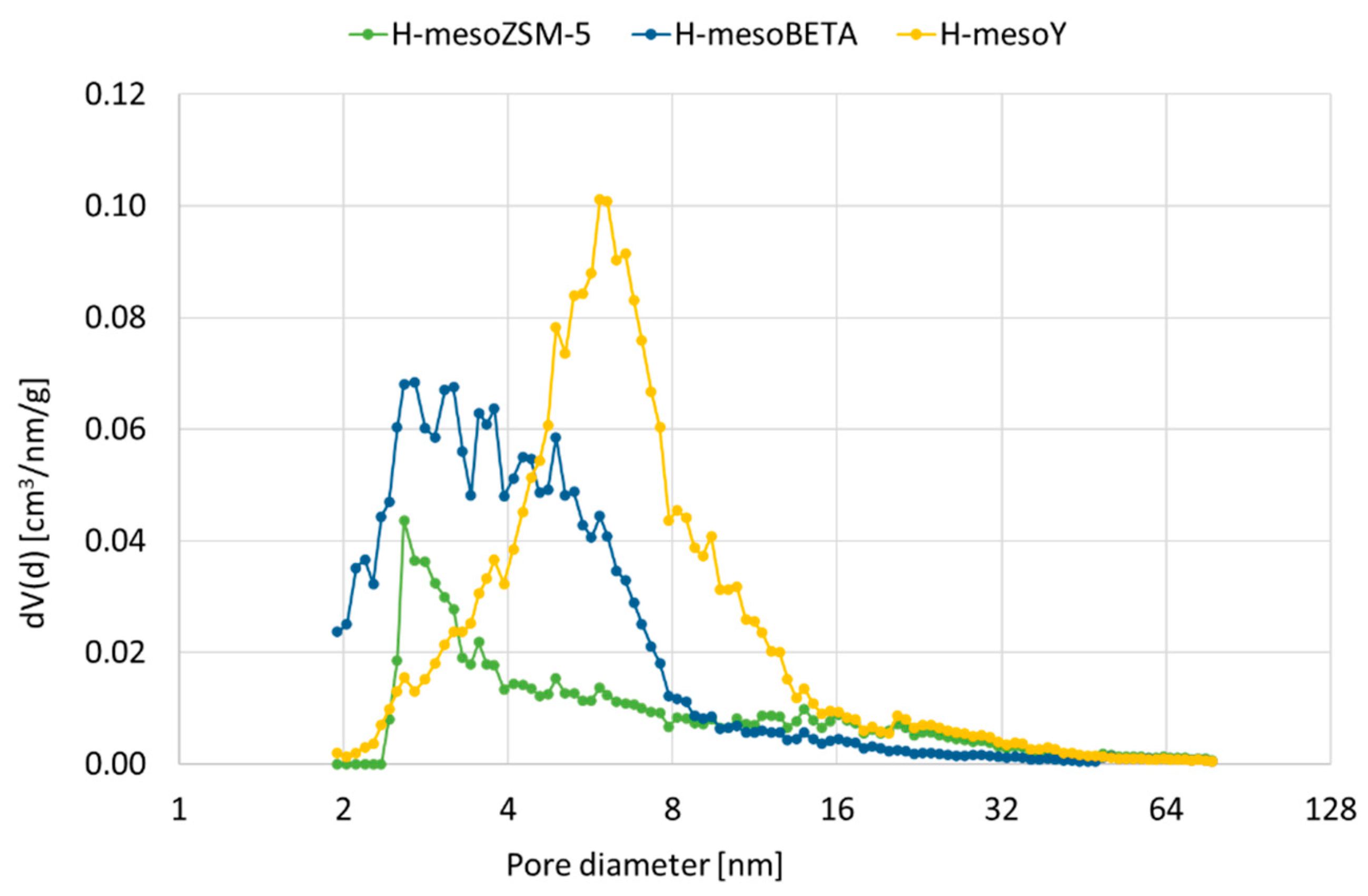
Pores in the meso size range of 2 to 16 nm were formed for all materials, as shown in Figure 1. However, mesoZSM-5 shows a maximum at 3 nm, whereas the distribution for mesoBETA is more dispersed, with most porosity between 2 and 8 nm. For mesoY, which had almost completely lost its microporosity, most porosity can be found around 6 nm. For the more severe treatments, not included in Figure 1, the pore distribution remains broad, but the average pore size is increased.

Figure 1.
Pore size distribution for treated zeolites H-mesoZSM-5, H-mesoBETA and H-mesoY.
Subsequently, these zeolites were used as support material for the preparation of the Co-based bif. catalysts. A list of the catalysts prepared via incipient wetness impregnation can be found in Table 2, including the Co loading and average Co3O4 particle size. Besides the bif. zeolitic catalysts, the mesoporous Co/SiO2 was also prepared and included, as was a commercially available Co + Ru/Al2O3 reference catalyst.
Table 2.
All catalysts, including the cobalt loading and average particle size, determined by the Scherrer equation for the 2θ = 43° diffraction.
For the preparations on mesoporosity-containing supports, the IW procedure provided catalysts with an average Co3O4 particle size in the 10–15 nm range. The microporous (parent) zeolites provided a lower dispersion, especially Co/H-ZSM-5 (28.2 nm) and Co/H-Y (22.0 nm). A notable difference was the 4.9 nm for Co + Ru/Al2O3, which is related to the presence of a small amount of Ru known to improve Co dispersion upon preparation [14].
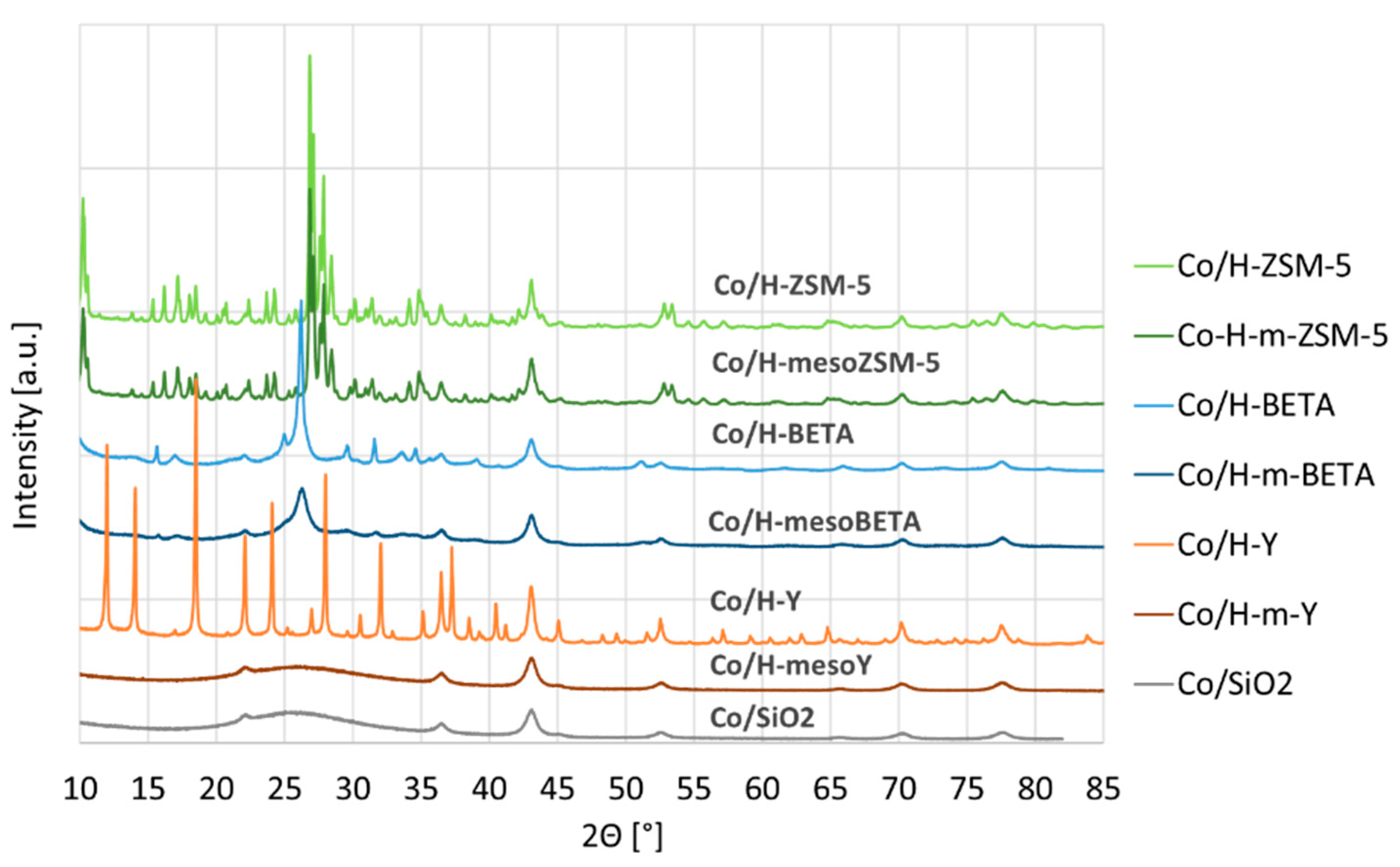
Besides the Co particle sizes, XRD also revealed the loss of support crystallinity for Co/H-mesoY (see Figure 2). Clearly, the desilication resulted in the formation of an amorphous phase similar to Co/SiO2, which is in line with the loss of microporosity demonstrated by the N2 physisorption. For both ZSM-5 and BETA, the crystallinity was largely maintained.
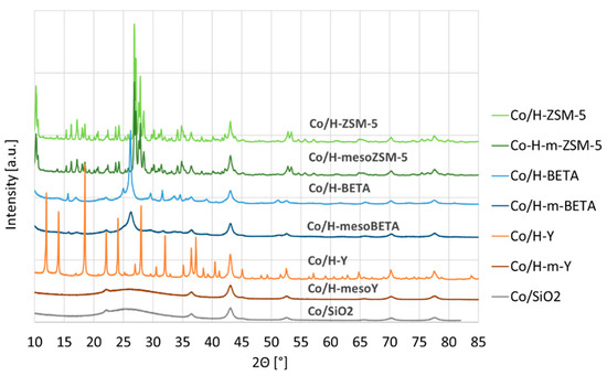
Figure 2.
XRD patterns of the supported Co catalysts.
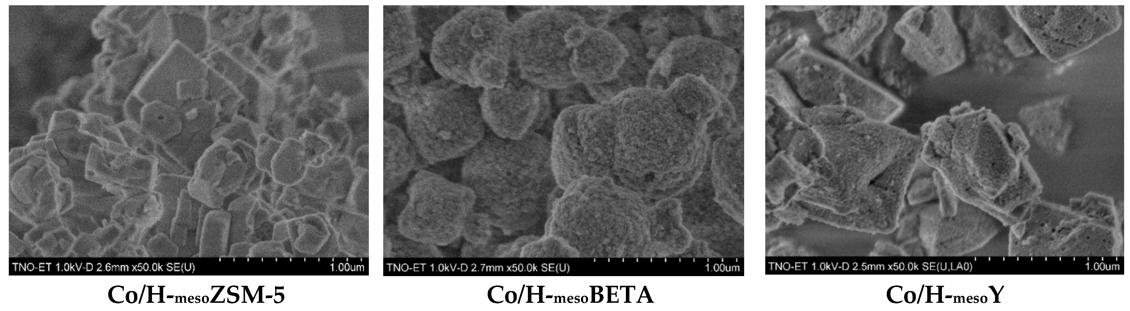
SEM images were obtained for all three bif. catalysts, which can be found in Figure 3. The images show that most zeolite crystallites are in the size range of 0.2–1 µm, and no obvious morphology changes have occurred as a result of the desilication. Defects in the form of small (20–50 nm) holes/macropores were observed on the surface of Co/H-mesoY particles; however, these were also observed in the parent H-Y material and were most likely created by the original steam treatment and acid leaching [15]. For all bif. catalysts, the resolution did not allow for the visualization of the Co3O4 nanoparticles.
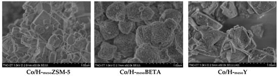
Figure 3.
SEM images of the bif. catalysts.
2.2. Catalyst Performance in FTS
The results of the catalytic experiments can be found in Table 3. Five bif. and the two reference catalysts were included in the catalytic tests under FTS conditions at 220 °C and 240 °C. In order to maintain the conversion in the desired range, the WHSV at 240 °C was increased from 2 h−1 to 4 h−1. Furthermore, the condensed liquids from the reactor’s hot (wax) and cold (lights, water) separators were collected, and their analysis is reported separately in Section 2.3.
Table 3.
FTS performance of the Co catalysts under 2 reaction conditions.
A comparison of the results indicates that the reference catalysts Co + Ru/Al2O3 and Co/SiO2 performed within the expected range, with C5+ selectivities of, respectively, 77% and 78%, with 11% and 12% CH4 formation. Moreover, Co + Ru/Al2O3 showed a high activity of 2.8 h−1, in line with the higher cobalt dispersion. At the increased temperature (240 °C), the activity increased significantly at a slight drop in selectivity for both.
For the ZSM-5-based catalysts, the activities are much reduced compared to Co/SiO2, and Co/H-ZSM-5 showed a remarkably high CH4 formation at 50.7%, resulting in a low liquid selectivity (SC5+) of only 30.9%. For the mesoporous Co/mesoZSM-5, the selectivity improved significantly to 70.6% with only 16.8% CH4, i.e., the presence of mesopores resulted in a higher liquid yield due to a lower CH4 by-product formation. This could be the result of less direct CO hydrogenation over unselective Co sites (strong support interaction) or because of improved mass transfer through the pores avoiding excessive hydrocracking in the micropores. At 240 °C, the selectivity was not much affected, although the activity increased about two-fold. As can be observed, the CO conversion increases only slightly, which can be explained by the higher WHSV.
With Co/H-mesoBETA, comparable activity and selectivity were obtained. In the presence of Co/H-mesoBETA, the SC5+ reached 75.5% at 240 °C, which approaches the selectivity of the reference mesoporous Co/SiO2. Again, this is an indication that the creation of hierarchical mesoporosity improves the yield of liquid products.
When Co/H-Y was applied, the SC5+ was still reasonable at 70.3% with 17.3% CH4 formation at 220 °C, but the C5+ decreased substantially to 51.0% at 240 °C. For Co/H-mesoY, the C5+ selectivity increased even further to 76.7% with little CH4 formation (11.5%).
The absence of wax provides a first indication that (hydro-)isomerization/cracking has occurred. When inspecting the hot and cold separators for all experiments, it was found that Co/H-ZSM-5, Co/H-mesoZSM-5 and Co/H-mesoBETA did not produce solid wax. For the experiments at 240 °C, the hot separator of Co/H-mesoBETA contained a slightly yellow oil and that of Co/H-mesoZSM-5 a viscous white paste. This is unlike the white solid wax obtained from the reference catalysts and the H-Y-based Co catalysts. In short, the H-ZSM-5 and H-BETA catalysts all (still) contained active Bronsted acid sites, even after desilication treatment, where H-Y did not.
2.3. Liquid Product Analysis
From the hot gas analysis during the FTS experiments, the SC5+ was determined, as described in the previous section, but additional analysis of the liquid condensates is required to determine its composition and hydrocarbon number distribution. The additional information obtained from these analyses are included in Table 4. This includes the selectivities towards liquids (SC5+), towards components in the jet fuel boiling range (SC8-C16) and towards wax (SC21+).
Table 4.
Product distribution determined from the FTS liquids.
As can be observed, the reference catalyst has a high SC5+ of 77.4% due to the formation of much wax, which is the (high α) approach of conventional FTS processes. For the mesoporous Co/HmesoZSM-5 and Co/HmesoBETA catalysts, the production of wax was, as desired, much lower, with 9.5% and 3.5% at 220 °C. For Co/H-mesoY, however, much wax was still produced, with 22.1% at 220 °C, which is similar to that of the reference catalysts. It appears that almost no hydrocracking activity was present over the H-Y catalysts.
Additionally, added to Table 4 is the C8,iso/C8,total ratio, an indicator for hydroisomerization and cracking activity. It describes the percentage of C8 isomers different from n-octane and n-octenes, divided by all C8 components, including n-octane and n-octenes. A higher ratio, thus, indicates a high quantity of isomers, and it is thereby an indicator for isomerization and cracking. Typically, the FTS syncrude contains predominantly linear n-alkanes and a fraction of n-alkenes. Indeed, the reference catalyst provides a very low C8,iso/C8,total ratio of 6.1 at 220 °C and 12.1 at 240 °C, with the main product being n-octane with some n-octene. On the contrary, Co/HmesoZSM-5 and Co/HmesoBETA provided a ratio of 74.1% and 64.7% at 220 °C due to the formation of many C8 isomers. At 240 °C this increased even further to, respectively, 94.0% and 67.4%. For Co/H-mesoY wax was still formed and, indeed, also the C8,iso/C8,total was much lower at 21.4% (220 °C) and 21.3 (240 °C).
3. Discussion
The desilication treatment has been already demonstrated for MFI-type zeolites and BETA-type zeolites, where the Al framework stability was found to be somewhat lower for the latter at similar Si/Al ratios [13]. In this work, with the described treatment, the preparation of the hierarchical structures was successful for both zeolite types. Zeolite Y was also selected and included because it is already used industrially in fluidized catalytic cracking, hydrocracking and alkylation. Unfortunately, the desilication treatment of H-Y was unsuccessful because the microporosity disappeared upon the desilication treatment, as demonstrated by N2 physisorption. Zeolite Y has a relatively high Al content when prepared and is treated/stabilized to obtain higher Si/Al ratios. The zeolite Y used in this work from Zeolyst (CBV760) has already been steam-treated and acid-leached to arrive at a Si/Al of 27 [16,17]. Apparently, this makes the structure vulnerable towards alkaline treatment, as the microporosity had disappeared by the 0.2 M NaOH treatment. This is confirmed by literature work that showed the successful introduction of mesoporosity upon a much milder treatment of 0.05 M at room temperature [15]. The loss of acidity was confirmed by the catalyst screening, with very little isomerization products for meso-Y (and also the parent Co/H-Y).
Additionally, XRD analysis revealed the complete loss of crystallinity for zeolite Y. The BETA structure also starts to show peak broadening of the characteristic diffractions, i.e., a more severe treatment would probably lead to a loss of crystallinity and, therefore, microporosity. As is known, ZSM-5 has a very stable framework structure, which showed to be most resistant against alkaline treatment, as demonstrated by the 0.5 M-treated material, which still did not result in a complete microporosity loss.
In all preparations, the incipient wetness impregnation procedure was used to load Co. In IW preparations, the volume of the metal salt solution should match the available pore volume. This resulted in a poor distribution for the parent zeolites. Due to the microporosity of the parent zeolite, the amount of liquid used is, therefore, much less at a higher Co salt solution. This, in combination with Co mass transfer through/in the micropores, resulted in the poor dispersion, with Co3O4 particles larger than 20 nm, and with this the lower activity in FTS. This is unlike the mesoporous zeolites that have more available surface area and, therefore, an improved Co dispersion. For example, Co/H-Y displayed an activity of 1.0 h−1 where the mesoporosity improved the activity to 1.9 h−1, because the corresponding Co3O4 particle sizes were, respectively, 22 nm and 13 nm. Furthermore, the commercial variant, although not prepared under identical conditions, contains 0.27% Ru as the promotor. Its presence is known to facilitate the Co dispersion upon calcination [14]. Additionally, indeed, the much smaller 4.9 nm particles improved the catalyst activity, whereas the selectivity is not enhanced notably. It was chosen in this work to not add additional promotors to the prepared cobalt catalysts, as the focus was on the potential of mesoporous zeolites.
The catalyst screening tests under FTS conditions showed the good performance of the reference catalysts, with selectivities of 77% and 78% for, respectively, Co + Ru/Al2O3 and Co/SiO2 at 220 °C. For the former, from the carbon distribution, it was established that this corresponds to an α value of 0.88 at 220 °C, which is in line with what is reported in the literature [18]. At 240 °C, the selectivity shifts to a lower carbon number with an α value of 0.85. It also shows that the support effect between mesoporous alumina and silica is limited [9].
It has been reported that the introduction of zeolites as Co support is not desired, as this results in much CH4 co-production. This can be found in the literature, for instance, with selectivities for CH4 of 21–24% and C5+ of 60% for Co/H-ZSM-5 [8] and, respectively, 23% and 51% for Co/H-Y [9]. In this work, Co/H-Y, indeed, also showed a selectivity to CH4 of 22.7% and to C5+ of 51.0% at 240 °C. For Co/H-ZSM-5, however, a much lower selectivity of 50.7% for CH4 and 30.9% for C5+ was obtained. This especially high methanation is caused by the strong Co–zeolite interaction, as small Co crystals with coordinately unsaturated surface sites are very active in CO hydrogenation and hydrogenolysis [19] in combination with mass transfer limitations in, especially, the micropores catalysts. Additional spectroscopy, such as TEM and/or IR, are required to verify that this is, indeed, the case here for the Co/H-ZSM-5 catalyst.
The introduction of mesoporosity clearly resulted in improved liquid selectivity. For mesoZSM-5, the C5+ selectivity increased to 70.6%. This was mostly due to the lower CH4 production, with 16.8% instead of 50.7% for the parent zeolite, which is only slightly more than the 10–12% for the reference catalysts. An even higher selectivity for mesoBETA was obtained with a C5+ selectivity of 75.5% at 240 °C, which is in the same range as the reference catalysts.
Interestingly, where conventionally the selectivity drops when the reaction temperature is increased, this trend was broken for the bif. ZSM-5 and BETA, whose selectivity for C5+ slightly improved at 240 °C because the methane production decreased slightly. This was most likely caused by the improved mass transfer at the higher temperature, in combination with the greater gas velocity (WHSV 4 h−1) at 240 °C.
Indeed, the liquid fractions revealed that the wax production was very low for the mesoporous ZSM-5 and BETA catalysts. As the liquid selectivity was high, this means that hydrocracking has provided a narrower product distribution, exactly as desired. Over Co/mesoH-Y this was not the case, due to a lack of acidity confirmed by the physisorption and XRD analysis. For Co/mesoZSM-5, the highest 35.5% C8–C16 was obtained at 220 °C, even though also much wax was produced. Mild hydrocracking produced hydrocarbons in the desired range. At higher temperature, the cracking starts to dominate, and products shift to a lower carbon number, with the 51.1% C5–C10 characteristic for gasoline. For Co/mesoH-Y, the highest C8–C16 was obtained at 240 °C at 41.0%.
To determine whether this C8-C16 boiling ranges is suitable as jet fuel, the most common jet A-1 aviation fuel specifications are listed in Table 5. As for its chemical composition, the aromatic content is restricted to 25%, with a minimum at 8% for synthetic fuels. Indirectly, its composition is restricted by the freezing point of −47°C. This low freezing point implies that a high branched (iso-) hydrocarbon content is desired, as n-paraffins typically have a high melting point. It has been shown that an iso-paraffin to linear paraffin ratio of 1:1 up to 2:1 is sufficient, but an even higher ratio allows more and heavier paraffins to be included [20]. At the highest 41.0% selectivity for Co/mesoH-BETA, the share of iso-C8 is 67.4% equal to 2.1:1, which would meet the requirement. Additionally, Co/mesoZSM-5 meets the desired quality at a decent yield.
Table 5.
Selected properties of jet A-1 fuel according to DCSEA 134/A [21].
Future research will focus on identifying the catalyst’s acidity and porosity in more detail and correlate this to performance. With this data, the catalyst properties can be tuned to achieve the highest jet fuel yield. In parallel, prolonged duration tests will be carried out to identify the long-term stability of the bif. catalysts, especially with regard to coke formation and, possibly, the loss in effectiveness due to dealumination or desilication under reaction conditions.
4. Materials and Methods
Zeolites NH4-ZSM-5 (CBV5524G, Si/Al = 25), NH4-BETA (CP814C, Si/Al = 19) and H-Y (CBV 760, Si/Al = 30) were obtained from Zeolyst (Farmsum, The Netherlands). Silica gel, Davisil Grade 633, PS: 37–74 µm, SA: 480 m2/g, PV: 0.75 mL/g, pore size: 6 nm and Co(NO3)2.6H2O (≥99.0%) were obtained from Merck (Schiphol-Rijk, The Netherlands). Moreover, α-alumina (≥99.5%, 0.04 m2/g, 0.015 mL/g, PS: 300–600 µm), used as an inert in the reactors, was obtained from Strem (Bischheim, France). The reference LTFT catalyst Co + Ru/Al2O3 was obtained from Riogen (Monmouth Junction, NJ, USA).
4.1. Preparation of the Mesoporous Supports and Catalysts
It has been shown that desilication is an effective method, as demonstrated by its commercial application [22]. Zeolites NH4-ZSM-5 and NH4-BETA were dried at 120 °C for 15 h followed by calcination at 550 °C for 5 h to obtain the H+ form. For desilication, all three zeolites were treated with 0.2 M NaOH, as described in detail elsewhere [13,23]. The zeolite, 10 g, was suspended in 300 mL 0.2 M NaOH and stirred vigorously. Subsequently, the mixture was heated up to 65 °C and stirred for an additional 30 min. Then, the suspension was cooled to room temperature and centrifuged at 4700 rpm for 15 min, after which the supernatant was decanted. The zeolite precipitate was washed 2× with 200 mL water. Then, the zeolite was ion exchanged with 3 × 200 mL 0.5 M NH4NO3 and washed with demi water to remove excess NH4NO3. The product was then dried at 120 °C for 15 h (1 °C/min), followed by calcination for 5 h at 550 °C (2 °C/min).
All samples were loaded with approximately 10 wt% cobalt through incipient wetness (IW) impregnation. An aqueous solution of Co(NO3)2.6H2O was added dropwise to the support sample while mixing thoroughly. Then, the sample was dried at 120 °C for 15 h (1 °C/min) followed by calcination at 400 °C for 2 h (2 °C/min ramp).
4.2. Catalyst Characterization
Elemental analysis was performed via ICP-OES using a Thermo ICAP 6600 (Thermoscientific, Bleiswijk, The Netherlands). Samples were digested using a sulfuric acid, hydrogen fluoride and hydrogen peroxide mixture in a microwave oven.
N2 physisorption was performed in an Autosorb-iQ-C unit (Quantachrome Instruments, Boyton Beach, FL, USA) at liquid nitrogen temperature (−196 °C). Prior to the experiment, approximately 0.1 g of the samples was degassed overnight in the degas station of the same Autosorb-iQ-C under vacuum at 350 °C.
SEM images were obtained using a 30 kV Hitachi SU-70 (Hitachi, Krefeld, Germany). Samples were prepared by placing some of the analyte on carbon tape without additional coating. Images were obtained under low voltage (2 kV decelerated to 1 kV) and low current (23 µA) and a short working distance of 2.6 mm for high-resolution images. For EDX analysis, the samples were coated with Pt/Pd to increase conductivity and measured under low voltage (2 kV) and a high beam current.
X-ray diffraction (XRD) measurements were performed in an Empyrean diffractometer (Malvern Panalytical, Almelo, The Netherlands) using Co Kα radiation (λ = 0.17890 nm) on a spinning silicon wafer. Samples were measured in the 2θ region from 5° to 120°. For the determination of the average particle size, the diffraction at 43° 2θ was used.
4.3. Catalytic Experiments
The catalyst tests were performed in a 4-flow reactor unit. This unit consists of 4 parallel tubular reactors placed in a single heated block to run under identical conditions, i.e., feed composition, flow, temperature, pressure and gas/liquid separation. Here, the flow of the required gas mixture is set using a Coriolis mass-flow controller. The condensation of the wax and light hydrocarbons from the reactor outlet gas occurs in, respectively, a hot (170 °C) and cold (5 °C) separator at the reactor pressure. The stainless-steel reactor tubes have an inner diameter of 8 mm, and a 10 cm-long isothermal zone with an axially placed 3-point thermocouple. Mixtures of 1.5 g catalyst and α-alumina (inert) were placed in the isothermal zone of each reactor tube for the catalytic runs.
All catalysts were activated by introducing 50 vol% H2 in N2 at 1 barg at 340 °C for 1 h at 1 °C/min with a WHSV of 3.3 ggasgcat−1h−1. For setting the reference reaction conditions, consecutively, the reactors were allowed to cool to 220 °C, the flow was set to 2.0 ggasgcat−1h−1, the pressure was set to 20 barg, followed by slow (3 h) introduction of CO to reach the desired gas composition of 32 vol% CO, 63 vol% H2 and 5 vol% N2. Gas analysis results were obtained under pseudo-steady-state conditions at least 15 h after the desired reaction conditions were established.
Gas samples from each reactor were withdrawn downstream of the hot separators. The gases were measured using an online GC equipped with separate channels for the detection of N2, Ar, CO2, CH4, CO (HS-N column with TCD detector), H2 (Molsieve 5A column with TCD detector) and C1–C4 (PlotQ column with FID detector).
Condensates from the hot/cold separators were quantified using, respectively, an Agilent 7890A 5975C GC-MS (Agilent, Middelburg, The Netherlands) and a Thermo Trace 1310 GC-FID (Thermoscientific, Bleiswijk, The Netherlands), both equipped with a J&W VF-5ms (Agilent, Middelburg, The Netherlands) capillary column (30 m, 0.25 mm, 0.25 µm).
Conversion and selectivity were calculated based on Equations (1)–(3):
where ΧCO is the CO conversion in % and FCO is the molar carbon flow of CO. SCn represents the carbon selectivity to all components with n carbon atoms, with FCn as the corresponding molar carbon flow. Finally, SC5+ defines the liquid carbon selectivity.
ΧCO [C%] = (FCO, in − FCO, out)/ FCO, in × 100%
SCn [C%] = FCn/(FCO, in − FCO, out) × 100%
SC5+ [C%] = 100% − Σ SC1–C4
5. Conclusions
The hierarchical zeolites H-mesoZSM-5 and H-mesoBETA were successfully prepared via desilication and applied as supports for the bif. catalysts Co/H-mesoZSM-5 and Co/H-mesoBETA.
The same desilication treatment for H-mesoY was less successful, as the desilication treatment resulted in a loss of microporosity and could, therefore, not be considered to be hierarchical.
Due to the loss of microporosity, Co/H-mesoY showed similar activity and selectivities as the reference (mesoporous) FTS catalysts and a lack of hydrocracking. Therefore, the catalyst can also not be considered to be a bifunctional catalyst.
Co/H-mesoZSM-5 and Co/H-mesoBETA showed great potential for the direct production of jet fuel as bifunctional catalysts. Firstly, the direct jet fuel yields under FTS conditions were high at, respectively, 30.4% and 41.0% and, secondly, the hydrocracking activity resulted in the high isomer/branched hydrocarbon content desired to reach jet fuel specifications.
This work clearly reveals the possibility of the direct conversion of syngas into jet fuel using catalysts that can be prepared in few steps from commercially available materials. Nevertheless, more research is needed to unravel the relationship between the catalyst’s acidity, porosity and catalytic performance to further enhance the selectivity and yield.
Author Contributions
Conceptualization, E.B., S.G. and B.V.; methodology, E.B., T.N. and D.S.; validation, E.B., T.N. and D.S.; formal analysis, E.B. and T.N.; investigation, E.B., T.N. and D.S.; data curation, E.B. and T.N.; writing—original draft preparation, E.B., S.G. and B.V.; writing—review and editing, E.B.; supervision, S.G. and B.V.; project administration, S.G.; funding acquisition, E.B., S.G. and B.V. All authors have read and agreed to the published version of the manuscript.
Funding
This research was part of the GLAMOUR project and has received funding from the European Union’s Horizon 2020 research and innovation programme under grant agreement No 884197.
Data Availability Statement
The data is contained within the article.
Acknowledgments
The authors would like to greatly acknowledge and thank VITO for performing the XRD measurements that are part this work. Furthermore, the authors would like to acknowledge and thank Ben van Egmond for the comprehensive FTS liquid GC analyses, Xiaoqian Lu for the SEM-EDX measurements and Gertjan Herder for providing the N2 physisorption data.
Conflicts of Interest
The funders had no role in the design of the study; in the collection, analyses, or interpretation of data; in the writing of the manuscript, or in the decision to publish the results.
References
- Allan, J.; Bansard, J.; Jones, N.; Luomi, M. Glasgow Climate Change Conference: 31 October–13 November 2021; Earth Negotiations Bulletin: Winnipeg, MB, Canada, November 2021; Volume 12, pp. 1–40. [Google Scholar]
- Edenhofer, O.; Pichs-Madruga, R.; Sokona, Y.; Seyboth, K.; Matschoss, P.; Kadner, S.; Zwickel, T.; Eickemeier, P.; Hansen, G.; Schloemer, S.; et al. IPCC Renewable Energy Sources and Climate Change Mitigation; Cambridge University Press: Cambridge, UK; New York, NY, USA, 2011; p. 1075. [Google Scholar]
- Renewable Energy Directive (REDII). Directive (EU) 2018/2001 of the European Parliament and of the Council of 11 December 2018 on the promotion of the use of energy from renewable sources (Text with EEA relevance). Off. J. Eur. Union 2018. Available online: https://eur-lex.europa.eu/eli/dir/2018/2001/oj (accessed on 31 January 2022).
- The European Advanced Biofuels Flightpath, Microsoft Word—2011 06 20 EU Declaration Biofuels in Aviation.doc (europa.eu). Available online: https://ec.europa.eu/energy/sites/ener/files/20110622_biofuels_flight_path_launch.pdf (accessed on 31 January 2022).
- Glamour Project. Available online: www.glamour-project.eu (accessed on 31 January 2022).
- Sie, T.; Senden, M.M.G.; Van Wechem, H.M.H. Conversion of natural gas to transportation fuels via the shell middle distillate synthesis process (MSDS). Catal. Today 1991, 8, 371–394. [Google Scholar] [CrossRef]
- van de Loosdrecht, J.; Botes, F.G.; Ciobîcă, I.M.; Ferreira, A.; Gibson, P.; Moodley, D.; Saib, A.; Visagie, J.; Weststrate, C.; Niemantsverdriet, H. Fischer–Tropsch Synthesis: Catalysts and Chemistry. In Comprehensive Inorganic Chemistry II; Reedijk, J., Poeppelmeier, K., Eds.; Elsevier: Amsterdam, The Netherlands, 2013; Volume 7, pp. 525–557. [Google Scholar] [CrossRef]
- Sartipi, S.; Parashar, K.; Valero-Romero, M.; Santos, V.P.; van der Linden, B.; Makkee, M.; Kapteijn, F.; Gascon, J. Hierarchical H-ZSM-5-supported cobalt for the direct synthesis of gasoline-range hydrocarbons from syngas: Advantages, limitations, and mechanistic insight. J. Catal. 2013, 305, 179–190. [Google Scholar] [CrossRef]
- Li, J.; He, Y.; Tan, L.; Zhang, P.; Peng, X.; Oruganti, A.; Yang, G.; Abe, H.; Wang, Y.; Tsubaki, N. Integrated tuneable synthesis of liquid fuels via Fischer–Tropsch technology. Nat. Catal. 2018, 1, 787–793. [Google Scholar] [CrossRef]
- Sartipi, S.; Parashar, K.; Makkee, M.; Gascon, J.; Kapteijn, F. Breaking the Fischer–Tropsch synthesis selectivity: Direct conversion of syngas to gasoline over hierarchical Co/H-ZSM-5 catalysts. Catal. Sci. Technol. 2013, 3, 572–575. [Google Scholar] [CrossRef] [Green Version]
- Wang, Z.; Wang, H.; Yang, C.; Wang, S.; Gao, P.; Sun, Y. Hierarchical ZSM-5 Supported CoMn Catalyst for the Production of Middle Distillate from Syngas. Ind. Eng. Chem. Res. 2021, 60, 5783–5791. [Google Scholar] [CrossRef]
- Groen, J.C.; Peffer, L.A.A.; Moulijn, J.A.; Perez-Ramirez, J. On the introduction of intracrystalline mesoporosity in zeolites upon desilication in alkaline medium. Microporous Mesoporous Mater. 2004, 69, 29–34. [Google Scholar] [CrossRef]
- Groen, J.C.; Abello, S.; Villaescusa, L.A.; Perez-Ramirez, J. Mesoporous beta zeolite obtained by desilication. Microporous Mesoporous Mater. 2008, 114, 93–102. [Google Scholar] [CrossRef]
- Zhang, Q.; Kang, J.; Wang, Y. Development of Novel Catalysts for Fischer–Tropsch Synthesis: Tuning the Product Selectivity. ChemCatChem 2010, 2, 1030–1058. [Google Scholar] [CrossRef]
- de Jong, K.P.; Zecevic, J.; Friedrich, H.; de Jongh, P.E.; Bulut, M.; van Donk, S.; Kenmogne, R.; Finiels, A.; Hulea, V.; Fajula, F. Zeolite Y Crystals with Trimodal Porosity as Ideal Hydrocracking Catalysts. Angew. Chem. Int. Ed. 2010, 49, 10074–10078. [Google Scholar] [CrossRef] [PubMed]
- Janssen, A.H.; Koster, A.J.; de Jong, K.P. Three-Dimensional Transmission Electron Microscopic Observations of Mesopores in Dealuminated Zeolite Y. Angew. Chem. Int. Ed. 2001, 40, 1102–1104. [Google Scholar] [CrossRef]
- Janssen, A.H.; Koster, A.J.; de Jong, K.P. On the Shape of the Mesopores in Zeolite Y: A Three-Dimensional Transmission Electron Microscopy Study Combined with Texture Analysis. J. Phys. Chem. B 2002, 106, 11905–11909. [Google Scholar] [CrossRef] [Green Version]
- Dry, M.E. The Fischer–Tropsch process: 1950–2000. Catal. Today 2002, 71, 227–241. [Google Scholar] [CrossRef]
- Den Breejen, J.P.; Radstake, P.B.; Bezemer, G.L.; Bitter, J.H.; Frøseth, V.; Holmen, A.; De Jong, K.P. On the origin of the cobalt particle size effects in Fischer-Tropsch catalysis. J. Am. Chem. Soc. 2009, 131, 7197–7203. [Google Scholar] [CrossRef] [PubMed]
- de Klerk, A. Fischer—Tropsch fuels refinery design. Energy Environ. Sci. 2011, 4, 1177–1205. [Google Scholar] [CrossRef]
- Exxonmobil Aviation. World Jet Fuel Specifications with Avgas Supplement, 2005 ed. Available online: www.exxonmobil.com/en/aviation/products-and-services/products/categories/fuels (accessed on 31 January 2022).
- Li, K.; Valla, J.; Garcia-Martinez, J. Realizing the Commercial Potential of Hierarchical Zeolites: New Opportunities in Catalytic Cracking. ChemCatChem 2013, 6, 46–66. [Google Scholar] [CrossRef]
- Groen, J.C.; Jansen, J.C.; Moulijn, J.A.; Perez-Ramirez, J. Optimal Aluminum-Assisted Mesoporosity Development in MFI Zeolites by Desilication. J. Phys. Chem. B 2004, 108, 13062–13065. [Google Scholar] [CrossRef]
Publisher’s Note: MDPI stays neutral with regard to jurisdictional claims in published maps and institutional affiliations. |
© 2022 by the authors. Licensee MDPI, Basel, Switzerland. This article is an open access article distributed under the terms and conditions of the Creative Commons Attribution (CC BY) license (https://creativecommons.org/licenses/by/4.0/).