Article

Study of the Relationship between Metal–Support Interactions and the Electrocatalytic Performance of Pt/Ti4O7 with Different Loadings

1
School of Chemical and Environmental Engineering, Shanghai Institute of Technology, Shanghai 201418, China
2
School of Materials Science and Engineering, Fuzhou University, Fuzhou 350108, China
3
Institute for Sustainable Energy, College of Sciences, Shanghai University, Shanghai 200444, China
*
Authors to whom correspondence should be addressed.
Catalysts 2022, 12(5), 480; https://doi.org/10.3390/catal12050480
Submission received: 18 March 2022 / Revised: 16 April 2022 / Accepted: 20 April 2022 / Published: 25 April 2022
(This article belongs to the Section Electrocatalysis)

Abstract

:
The application potential of Pt/Ti4O7 has been reported, but the lack of research on the relationship between Pt loading, MSI, and catalytic activity hinders further development. Micron-sized Ti4O7 powders synthesized by a thermal reduction method under an H2 atmosphere were used as a support material for Pt-based catalysts. Using a modified polyol method, Pt/Ti4O7-5, Pt/Ti4O7-10, and Pt/Ti4O7-20 with different mass ratios (Pt to Pt/Ti4O7 is 0.05, 0.1, 0.2) were successfully synthesized. Uniformly dispersed platinum nanoparticles exhibit disparate morphologies, rod-like for Pt/Ti4O7-5 and approximately spherical for Pt/Ti4O7-10 and Pt/Ti4O7-20. Small-angle deflections and lattice reconstruction induced by strong metal–support interactions were observed in Pt/Ti4O7-5, which indicated the formation of a new phase at the interface. However, lattice distortions and dislocations for higher loading samples imply the existence of weak metal–support interactions. A possible mechanism is proposed to explain the different morphologies and varying metal–support interactions (MSI). With X-ray photoelectron spectroscopy, spectrums of Pt and Ti display apparent shifts in binding energy compared with commercial Pt-C and non-platinized Ti4O7, which can properly explain the changes in absorption ability and oxygen reduction reaction activity, as described in the electrochemical results. The synthetic method, Pt loading, and surface coverage of the support play an important role in the adjustment of MSI, which gives significant guidance for better utilizing MSI to prepare the target catalyst.

1. Introduction

Advantages like high efficiency, environment friendly, and reactants bounteously make fuel cells a promising candidate for powering vehicles, as well as energy storage stations and portable power generation [1]. Although numerous studies have been carried out on non-precious metal catalysts, carbon-supported platinum nanoparticles (Pt/C) are still the most practical catalysts because of their intrinsic outstanding catalytic activities [2]. Carbon materials including Vulcan XC-72R, Ketjen Black, and Black Pearl are usually employed as supports in Pt/C catalysts. These carbon supports, however, are extremely susceptible to corrosion under the electrochemical condition, and such corrosion can lead to the agglomeration, dissolution, and detachment of Pt NPs (platinum nanoparticles) from carbon supports, which is identified as one of the major causes of performance degradation and a lifetime reduction of Pt/C catalysts [3]. Substantial efforts have been devoted to the exploration of alternative support materials for Pt NPs. Non-carbon materials such as nitrides, carbides, oxides, sulfides, borides, and metals have been used to support Pt NPs [4]. Compared to Pt/C catalysts, these non-carbon materials-supported Pt NPs exhibit improved stability/durability, which is ascribed to the resistance of non-carbon materials to electrochemical corrosion. Among the various non-carbon materials, transition metal oxides have received extensive attention for Pt NPs supporting because of their high electrochemical stability and thermal stability, as well as low-cost and easy manufacturing. Of all kinds of transition metal oxides, titanium dioxide (TiO2) has been the most extensively studied because of its abundance, non-toxicity, and wide application in photocatalysis, photovoltaics, and water splitting [5]. There have been several reports on preparing TiO2-supported Pt NPs catalysts (Pt/TiO2) [6,7,8,9,10]. These Pt/TiO2 catalysts, however, did not exhibit a comparable oxygen reduction reaction (ORR) catalytic performance to Pt/C catalysts, and the poor electroconductivity of TiO2 was considered the main reason [11] leading to the decreased catalytic activity of Pt/TiO2 catalysts. Although strategies such as doping TiO2 with Nb [12,13] or N [14,15] and compositing TiO2 with carbon material [16,17] have been proposed to improve the conductivity of TiO2 support, the ORR catalytic activities of Pt/TiO2 catalysts were still not as high as those of commercial Pt/C catalysts.
Ti4O7 was employed as the support for Pt NPs because Ti4O7 has electrical conductivity up to 1500 S·cm−1 at room temperature, which is comparable to graphitized carbon [18]. In addition, as a member of Magnéli phases titanium suboxides with the general formula of TinO2n−1 (3 < n < 10) [19], Ti4O7 exhibits excellent chemical and thermal stability, and especially high resistance to electrochemical corrosion [20]. Many researchers have explored synthesizing Pt/Ti4O7 to elevate the catalytic activity and stability for ORR in the cathodes of fuel cells [21,22,23,24]. All of the results illustrate that Pt/Ti4O7 displays superior stability whether in the rotating disk electrode or membrane electrode assembly test, while the electrochemical surface area (ECSA) and mass activity (MA) of Pt/Ti4O7 are inferior to the Pt/C catalyst. The intrinsic stability of Ti4O7 and its strong metal–support interactions (SMSI) are recognized to be important reasons for this superior stability. As for the relatively poor catalytic performance, the researchers attribute it to the low conductivity of metal oxides and low platinum utilization due to the aggregation of Pt NPs [24]. Based on the above shortcomings, after 2013, there was a blank period for studies of the Pt/Ti4O7 catalyst. However, in the last decade, there have been many research papers on metal oxide-supported catalysts used in propylene hydrogenation, hydrolytic ammoniation, the water-gas shift reaction, and other chemical fields [25,26,27,28]. Metal–support interactions (MSI) play an important role in catalytic activity and selectivity. This provides a new possible explanation for the poor electrochemical activity of the Pt/Ti4O7 catalyst, that is the MSI lead to the formation of a Pt-Ti bond at the interface, which reduces the active platinum content and leads to a decrease in catalytic activity. This hypothesis was first verified by the experiments in this article. Initially, low Pt loading (<5 wt%) was reported as limited by the low surface area of Ti4O7 [22]. Next, in order to improve the performance of Pt/Ti4O7 catalysts, a series of tasks were carried out, including the preparation of a high Ti4O7 -specific surface area [24,29] and a high number of Pt loading (40 wt%) Pt/Ti4O7 catalysts [30]. The Pt loading is often limited by the properties of the support, loading method, etc. None of the previous articles have explored the relationship between the electrocatalytic performance of Pt/Ti4O7 with different Pt loadings and MSI. It’s still a problem to tune the MSI to acquire an ideal catalyst with desirable properties.
In our experiments, Ti4O7-supported Pt NP (Pt/Ti4O7) catalysts with different Pt loading were prepared according to the modified polyol method. It was found that the MSI between Pt and the Ti3+ played a significant role during the formation of Pt nuclei and the subsequent growth of Pt NPs, and thus greatly affected the size and shape of Pt NPs on Ti4O7 support. Although the Ti4O7 support has very high electrical conductivity, Pt/Ti4O7 catalysts still displayed ORR catalytic activity worse than commercial Pt/C catalysts. A new possible explanation that the formation of Pt-Ti at the interface induced by the MSI is responsible for the reduction in catalytic performance. However, after the portion of Pt atoms which had MSI with Ti were excluded, we found that the Pt NPs exhibit an active surface area and catalytic activity that are comparable to commercial Pt/C catalysts. Our research results manifest that the catalytic activity of transition metal oxides-supported Pt NPs was affected by not only the poor electroconductivity of the support, but also the MSI.

2. Results and Discussion

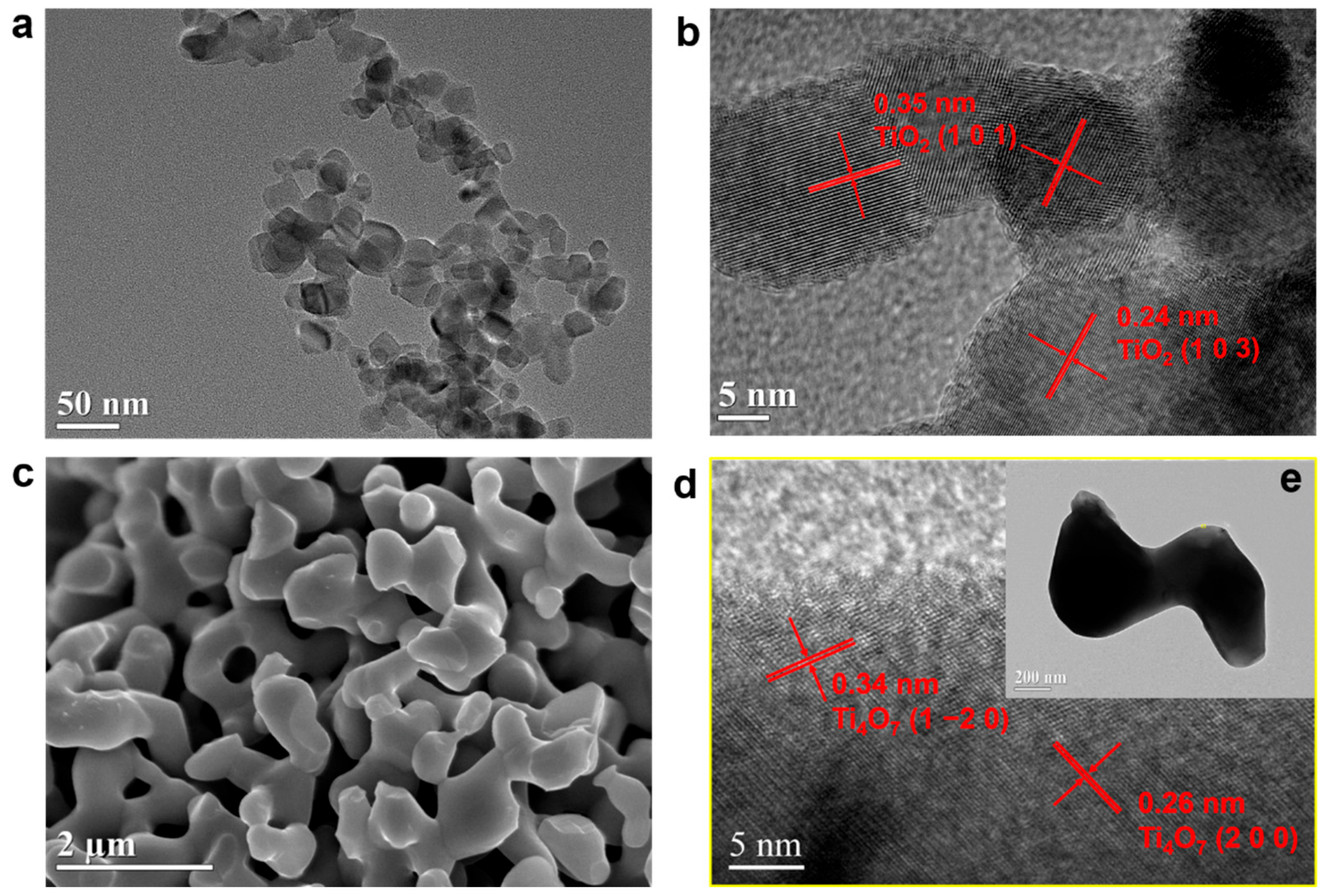
2.1. Preparation of Ti4O7

Ti4O7 was prepared by calcination of P25 (Aeroxide® TiO2) powder under H2 atmosphere. Figure 1a is a digital image of the pristine P25, in which the P25 powder looks like white flour. However, after being calcined under an H2 atmosphere at high temperature, the pristine P25 turns from white flour to dark granules. Figure 1b–d presents digital photos of the P25 powder calcined at different temperatures. As seen, after being calcined at 1123, 1173 and 1223 K, the P25 turned from white powder into grey-blue, black-blue, and black granules, respectively. XRD (X-ray diffraction) measurement was conducted to characterize the crystalline structures of the calcined P25 granules. For comparison, the XRD pattern of P25 was also recorded. As shown in Figure 1e, the P25 is composed of anatase and rutile TiO2, and the molar ratio of anatase to rutile can be obtained from the K-value method. The ratio of anatase to rutile is about 3:1, which is in accordance with the reference [31]. Figure 1f presents the XRD patterns of the calcined products of P25 at 1173 K. It can be seen from Figure S1 that P25-1123 consisted of Ti6O11, Ti5O7, and Ti4O7, while the diffraction peaks on the XRD pattern of P25-1173 are well indexed to the characteristic diffraction peaks of Ti4O7 (Figure 1f), indicating that P25-1173 contains only Ti4O7 and no other Magnéli phases. However, when the calcination temperature rises to 1223 K, the diffraction peaks on the XRD pattern match well with the JCPDS card NO. 76-1066, as shown in Figure S1, suggesting P25-1223 is composed of Ti3O5. It is reported Ti4O7 is very stable. In our work, we found that even after 4 months of storage in capped vials at room temperature, our prepared P25-1173 maintained its color and granular shape. XRD measurement proved that P25-1173 keeps its Ti4O7 crystalline structure after 4 months of storage (Figure S2).
A SEM (scanning electron microscope), TEM (transmission electron microscope), and HRTEM (high-resolution transmission electron microscope) were employed to investigate the morphology and lattice structure of P25-1173, and the TEM and HRTEM images of P25 were also recorded for comparison. As shown in Figure 2a,b, P25 exhibits a particular morphology with an average particle size of 20 nm, and the interplanar spacings of 0.35 nm and 0.24 nm correspond to the (1 0 1) and (1 0 3) crystal faces of anatase TiO2. Figure 2c,d show the SEM and HRTEM images of P25-1173, in which P25-1173 exhibits a micron to sub-micron irregular pore structure and the interplanar spacings of 0.34 nm and 0.26 nm are attributed to the (1 −2 0) and (2 0 0) crystalline faces of Ti4O7. The TEM image of P25-1173 is presented as an insert in Figure 2e, which indicates that coral-structured P25-1173 is composed of Ti4O7 submicron-plates. In the TEM and HRTEM images of P25-1173, no mesopores or micropores were observed, which accounted for the very small specific surface area of P25-1173. This specific surface area of P25-1173 was determined to be only 2.16 m2·g−1 by the Brannuaer-Emmet-Teller (BET) method.

2.2. Synthesized Pt/Ti4O7 Catalysts

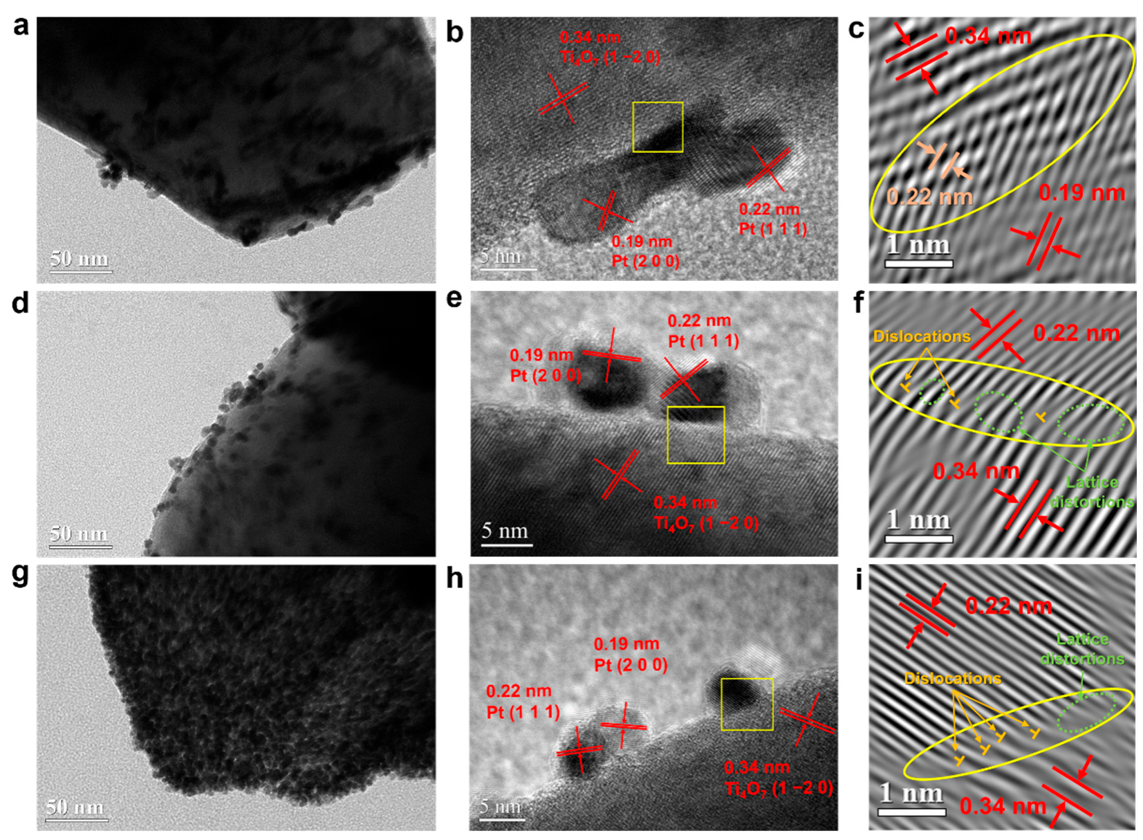
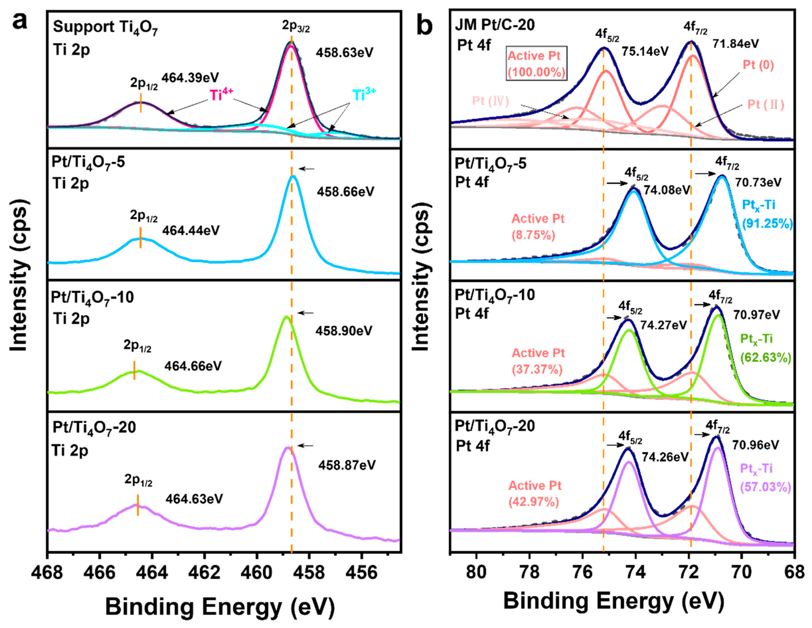
2.2.1. Morphologies and Crystalline Structures

Pt/Ti4O7 with different Pt loading levels were synthesized using the modified polyol method by varying the mass ratio of P25-1173 to Pt. XRD measurements were obtained to investigate the crystalline structures of the Pt/Ti4O7 samples with different Pt loadings. As shown in Figure 3a, even after 12 h of the reduction reaction at 433 K, the diffraction peaks of all the three Pt/Ti4O7 samples were still well indexed to the characteristic diffraction peaks of Ti4O7, implying that P25-1173 maintained its crystalline structure even after 12 h of reduction reaction. In addition to the diffraction peaks of Ti4O7, four new peaks emerged on the XRD patterns of the Pt/Ti4O7 samples. The four peaks at 40°, 46°, 67°, and 81° corresponded to the (1 1 1), (2 0 0), (2 2 0), and (3 1 1) reflections of Pt, suggesting successful loading of Pt on Ti4O7 in the three samples. Inductively coupled plasma-atomic emission spectrometry (ICP-AES) was used to measure the actual Pt loading in the samples, and the Pt loadings for Pt/Ti4O7-5, Pt/Ti4O7-10, and Pt/Ti4O7-20 were determined to be 3.48 wt%, 6.95 wt%, and 12.60 wt%, respectively. Figure S3 displays the SEM images of Pt/Ti4O7-5, Pt/Ti4O7-10, and Pt/Ti4O7-20. It can be seen from Figure S3 that P25-1173 kept its morphology after hours of thermal reduction. Energy dispersive X-ray (EDX) elemental mapping analysis shows that the Pt element is homogeneously dispersed on the Ti4O7 substrate in all three samples, despite the Pt loading. The particle size of Pt on a Ti4O7 substrate could be calculated according to the diffraction line of Pt (1 1 1) using the Scherrer equation:
τ = K λ / β cos θ ,
where τ is the mean size of the crystalline domains, K is the dimensionless shape factor (typical value is 0.9, varies with the actual shape), λ is the X-ray wavelength, β is the full width at half the maximum of the diffraction peak, and θ is the Bragg angle. The particle sizes of Pt for Pt/Ti4O7-5, Pt/Ti4O7-10, and Pt/Ti4O7-20 are calculated to be 10.7, 7.7, and 5.8 nm, respectively.
It is reported that as Ti3+ with electron configuration [Ar] 3d1 can induce d-orbital electrons’ transformation from TiOx (x < 2) to Pt (electron configuration: [Xe] 4f145d94s1), TiOx can easily combine with Pt [32,33]. Figure 3b exhibits the crystalline structure of Ti4O7 as its crystalline structure has been revealed. The blue octahedra indicate edge-sharing sites of rutile structure TiO2, and the green ones suggest face-sharing sites of corundum structure Ti2O3 [34]. It is because of the Ti3+ in Ti2O3 that Pt can be easily loaded on the Ti4O7 substrate.
A TEM and HRTEM were applied to further investigate the morphologies and crystalline structures of the Pt/Ti4O7 samples. Figure 4a is the TEM image of the Pt/Ti4O7-5, in which Pt nanorods of ca., 9.5 nm long and 5.3 nm wide, are observed on the Ti4O7 substrate. The size of the Pt nanorods obtained from the TEM image is very close to the size of the Pt particles calculated from the XRD pattern. It is seen in Figure 4a that the Pt nanorods are aggregated, and the aggregations of Pt nanorods are not evenly dispersed on the substrate. Figure 4b is the HRTEM image of Pt/Ti4O7-5, and the interplanar spacings of 0.34, 0.22, and 0.19 nm can be assigned to the Bragg reflections from Ti4O7 (1 −2 0), Pt (1 1 1), and Pt (2 0 0), respectively. The HRTEM image clearly shows that the Pt nanorods are confined in the lattice of the Ti4O7 rather than being adsorbed. An Inverse Fast Fourier Transform (IFFT) of the HRTEM image (Figure 4c) was applied to investigate the interface of the Pt nanorods and Ti4O7. The selected IFFT image shows that the Ti4O7 lattice and Pt lattice merge at the interface, which implies that Pt and Ti4O7 are fused at the interface.
Figure 4d is the TEM image of Pt/Ti4O7-10, in which the size of the Pt NPs is about 7.2 nm, which is almost consistent with the particle size obtained from the XRD pattern. Different from the Pt nanorods in Pt/Ti4O7-5, the Pt NPs in Pt/Ti4O7-10 are not aggregated. Instead, only several Pt NPs are agglomerated. The Pt agglomerates are dispersed more evenly on Ti4O7 than the aggregated Pt nanorods. The HRTEM image of Pt/Ti4O7-10 is illustrated in Figure 4e, in which the interplanar spacings corresponding to the Bragg reflections of Ti4O7 and Pt are observed. However, it can be seen from the HRTEM image that in Pt/Ti4O7-10, the Pt NPs seem to be adsorbed on the substrate rather than confined in the substrate lattice. The selected IFFT image (Figure 4f) reveals no lattice fusion, but lattice distortion is observed at the Pt and Ti4O7 interface. The lattice distortion comes from strong spin-split coupling, in which verifying Pt NPs are adsorbed on Ti4O7 in Pt/Ti4O7-10. Figure 4g,h shows the TEM and HRTEM images of Pt/Ti4O7-20, in which highly dispersed Pt NPs are spread on the Ti4O7 substrate. The size of the Pt NPs is about 5.9 nm, which is consistent with the particle size obtained from the XRD pattern. The selected IFFT image (Figure 4i) discloses the lattice distortions and dislocations [35] at the Pt and Ti4O7 interface, which indicate that in Pt/Ti4O7-20, the Pt NPs are adsorbed on Ti4O7.
To explain the reason why the particle size of Pt NPs on Ti4O7 decreases with increases in the mass ratio of Pt to Ti4O7, while the dispersion of Pt NPs increases with the mass ratio, a possible mechanism for deposition of Pt on Ti4O7 is proposed. As described in Figure 5, in a typical synthetic process, the mixture of diethylene glycol (DEG) and Ti4O7 is heated to 433 K. During the heating, reductive molecules such as diols, alkyds, aldehydes, carboxylic acids are generated due to the degradation and oxidation of DEG [36]. Except for the reducing agent, DEG performs as a solvent and stabilizer in the system. As a solvent, it has a relatively large viscosity, which is beneficial to the dispersion of relatively dense Ti4O7. Tightly adsorbed on the surface of nanoparticles, it provides electrostatic repulsion and steric hindrance between particles to inhibit aggregation and agglomeration, and thus acts as a stabilizer. The reductive molecules mentioned above can reduce Pt4+ into Pt2+ or Pt0. Thus, when the first several drops of H2PtCl6·6H2O/DEG solution are added into the heated DEG/Ti4O7 system, Pt nuclei are immediately formed due to the reduction of Pt4+. The formed Pt nuclei can either bind with the Ti4O7 substrate or remain in the DEG/Ti4O7 system. If the concentration of Ti4O7 is low, many nuclei will stay in the DEG/Ti4O7 system and grow into large Pt NPs with the continuous addition of a Pt precursor (Reaction Ⅰ). For the minimum support system (Pt/Ti4O7-5), since most of the nuclei are in the solution, the Reaction Ⅰ dominates, tending to generate larger Pt particles before combining with Ti4O7. The large nanoparticles will undergo deformation due to the SMSI and large gaps between Pt NPs, turning from nanoparticles into nanorods, and such deformation will easily result in the aggregation of nanorods [37,38,39]. However, if the concentration of Ti4O7 is high, most of the formed nuclei can be deposited on Ti4O7 (Reaction ⅠⅠ) because of the electron donation from Ti3+ to Pt. As almost no Pt nuclei existed in the DEG/Ti4O7 system, the continuous addition of the Pt precursor will lead to the generation of new Pt nuclei, and these Pt nuclei will also combine with the Ti4O7 substrate. Therefore, in Pt/Ti4O7-20, small Pt NPs are observed to be evenly dispersed on the substrate. Restricted by the limited gap between particles or the extremely high surface coverage of the support, Pt/Ti4O7-10, and Pt/Ti4O7-20 only suffered weak metal–support interactions (WMSI), which allowed the existence of slightly deformed, approximately spherical particles (Figure 4e,h) and the distortion of lattice fringes at the interface area (Figure 4f,i).

2.2.2. Electrocatalytic Performances of Pt/Ti4O7 Samples

Cyclic voltammetry (CV) was performed in a 0.5 M H2SO4 solution between −0.70 and 0.45 V (vs. Hg/Hg2SO4) at 0.05 V·s−1 to evaluate the ECSA of the Pt/Ti4O7 catalysts. Before the CV measurements, the 0.5 M H2SO4 solution was deaired by bubbling nitrogen for 20 min. Figure 6a displays the CV curves of Pt/Ti4O7 catalysts. For comparison, the CV curve of Ti4O7 is also recorded. As shown in Figure 6a, the Pt/Ti4O7 catalysts all present typical CV curves of polycrystalline Pt with clear hydrogen adsorption/desorption and oxidation/reduction regions, whereas Ti4O7 only shows the CV curve of a featureless quasi-rectangle shape. The ECSA of Pt/Ti4O7 catalysts can be obtained from the hydrogen underpotential deposition (Hupd) region by integrating the hydrogen adsorption/desorption region after double-layer current correction, assuming a pseudo-capacity of 210 μC·cmPt−2 for polycrystalline Pt. The Hupd [cmPt2] was normalized by the actual Pt loading used to express the ECSA [m2·gPt−1] [40]. Figure 6c shows the ECSA for the Pt/Ti4O7 catalysts based on the CV curves (Figure 6a). As seen, the ECSAs for Pt/Ti4O7-5, Pt/Ti4O7-10, and Pt/Ti4O7-20 were calculated to be 4.56, 15.86, and 25.65 m2·gtotal Pt−1, respectively, which means that for Pt/Ti4O7 catalysts, the lower the Pt loading, the smaller the ECSA. The ECSA is three times as high compared to around 7 m2·gPt−1 (Pt loading: 20 wt%) in Senevirathne’s article [23], while only possessing a half value of that fiber-like, nanostructured Ti4O7-loaded Pt catalyst [24]. We also investigated the ECSA of commercial Pt/C catalysts with different Pt loadings. Figure S4 shows the CV curves of the commercial JM Pt/C with 20% and 40% Pt loading, and the ECSAs are calculated to be 79.0 and 58.1 m2·gPt−1 for JM Pt/C-40 and JM Pt/C-20, separately, which suggest that for Pt/C catalysts, the ECSA is kept at ca. 70 m2·gPt−1 no matter how much Pt is loaded.
The electrocatalytic activity of catalysts towards ORR was examined by a linear sweep voltammetry (LSV) technique in an oxygen-saturated 0.1 M KOH solution at a scan rate of 10 mV·s−1. The LSV curves for the support Ti4O7 and Vulcan XC-72R in Figure 6b snd Figure S7 exhibit similar ORR activity with an onset potential around 0.70 V and a peak potential around 0.45 V. As shown in Figure 6b, Pt/Ti4O7-5 catalyst, to a large extent, performs the characteristics of Ti4O7 rather than Pt, and the onset potential of ORR on an electrode is ca. 0.91 V, which is about 21 mV positive to the Ti4O7 electrode. Pt/Ti4O7-10 and Pt/Ti4O7-20 catalysts exhibit a comparable ORR activity to Pt/C catalyst. The onset potentials for ORR of Pt/Ti4O7-10 and Pt/Ti4O7-20 are ca. 0.99 and 1.01 V, which is about 4 and 2 mV negative to commercial Pt/C, and the half-wave potential towards ORR of the two are ca. 0.83 and 0.85 V, which is about 1 and 3 mV positive to the Pt/C catalyst.
Why can Pt loading affect the ECSA of Pt/Ti4O7 catalysts so much, yet have little effect on the ECSA of commercial Pt/C catalysts? Figure S5 presents the TEM images of JM Pt/C-20 and JM Pt/C-40. It is seen in both TEM images that the Pt NPs present a particular morphology with sizes around 3 nm, implying that the Pt NPs have similar specific surface areas in JM Pt/C-40 and JM Pt/C-20. Thus, we calculated the specific surface areas of the Pt NPs in the Pt/Ti4O7 catalysts. As shown in Figure S6, the specific surface area of Pt NPs were calculated to be 0.97, 0.83, and 1.0 ρ P t 1 for Pt/Ti4O7-5, Pt/Ti4O7-10, and Pt/Ti4O7-20, respectively, which indicates that the specific surface area of Pt NPs has nearly no effect on the ECSA of Pt/Ti4O7 catalysts.
Measurements were obtained by X-ray photoelectron spectroscopy (XPS) to analyze the surface electron structures of the catalysts. Figure 7a,b shows the high-resolution Ti 2p and Pt 4f XPS spectra of the Pt/Ti4O7 catalysts. The Ti 2p XPS spectrum of support Ti4O7 and the Pt 4f XPS spectrum of JM Pt/C-20 were also recorded for comparison. As shown in Figure 7a, Ti4O7 shows two peaks, at 458.63 and 464.39 eV, which are attributed to the Ti 2p3/2 and Ti 2p1/2 orbits, respectively [41,42,43]. However, on the spectra of the Pt/Ti4O7 catalysts, the Ti 2p3/2 and Ti 2p1/2 peaks both shift positively to a higher binding energy (BE), suggesting that there are should be fewer electrons surrounding the Ti atoms in Pt/Ti4O7 catalysts. Figure 7b presents the Pt 4f XPS spectra of Pt/Ti4O7 catalysts. The Pt 4f XPS spectra of a commercial Pt/C catalyst is also shown as the benchmark. There are two Pt 4f peaks, Pt 4f5/2 and Pt 4f7/2, located on 71.84 and 75.14 eV [44,45], shown on the Pt 4f XPS spectrum of the commercial Pt/C while the Pt 4f5/2 and Pt 4f7/2 peaks of the Pt/Ti4O7 catalysts all shift negatively to a lower BE. This suggests that there should be more electrons surrounding the Pt atoms in Pt/Ti4O7 catalysts compared to Pt/C. The shift of Ti 2p peaks to a higher BE and Pt 4f peaks to a lower BE discloses that in Pt/Ti4O7 catalysts, electrons are transferred from Ti atom to Pt atom [46,47]. The absolute values of ΔBE for Pt/Ti4O7 catalysts are shown in Table S1. It can be seen that Pt/Ti4O7-5 shows the biggest ΔBE (1.10 eV) for the Pt element, while Pt/Ti4O7-10 and Pt/Ti4O7-20 exhibit diminished values, 0.87 and 0.88 eV, indicating a stronger interaction between Pt NPs and Ti4O7 for Pt/Ti4O7-5.
As shown in Figure 7b, the spectrum for Pt/C consists of three pairs of overlapping curves: Pt (0), located at 71.83 and 75.11 eV; Pt (II), located at 72.97 and 76.18 eV; and Pt (IV), located at 75.51 and 78.75 eV, which are classified as “active Pt” and used as benchmarks. Zhao et al. [48] investigated the MSI between Pt NPs and TiO2 support. They found that during the formation of the surface Pt-Ti alloy, Ti atoms donate their electrons to Pt, and such a MSI reduced the affinity of the Pt atoms to H2. Therefore, the Pt 4f peaks are deconvoluted into the Pt 4f5/2 and Pt 4f7/2 peaks of “active Pt” and the Pt 4f5/2 and Pt 4f7/2 peaks of Ptx-Ti. The “active Pt” area was divided according to the commercial JM Pt/C-20 catalyst with the peak positions of 71.84 and 75.14 eV and the area ratio of 4f5/2 to 4f7/2 is 0.75 [49]. The relative amounts of active Pt and Ptx-Ti for three Pt/Ti4O7 catalysts can be calculated separately, as shown in Figure 7b. As the H2 adsorption on Pt atoms in the Pt-Ti phase is suppressed, we think that only the active Pt provides active sites for H2 adsorption/desorption. Thus, correct the ECSA calculation by using the active Pt loading instead of the actual Pt loading and the corrected ECSAs for Pt/Ti4O7-5, Pt/Ti4O7-10, and Pt/Ti4O7-20 are 52.11, 42.38, and 59.78 m2·gactive Pt−1, as shown in Figure 6c, which suggests that for Ti4O7 catalysts, the corrected ECSA is kept at ca. 50 m2·gPt−1 no matter how much Pt is loaded, complying with the general rules for Pt catalysts.
For a more accurate evaluation of the electrocatalytic activity of ORR, the kinetic current ( i k ) was calculated through the Koutecky–Levich equation:
1 i = 1 i L + 1 i k ,
where i is the actual current at 0.9V vs. RHE, i L is the limit current, and the MA was calculated using actual and active Pt loading normalizations, respectively. In Figure 6b, the shape of Pt/Ti4O7-5 deviates far from the four-electron reaction of normal platinum catalysts, and a reasonable i L cannot be determined, therefore only the MA of Pt/Ti4O7-10 and Pt/Ti4O7-20 were calculated. The MA of JM Pt/C-20 was also recorded according to Figure S7 for comparison. As shown in Figure 6d, Pt/Ti4O7 catalysts perform only half the activity of JM Pt/C-20 catalysts affected by MSI. However, it is slightly higher than the MA values for similar systems in the related literature, which are 22 [24] and 32 A·gPt−1 [11], respectively. Correct the mass activity with active Pt loading instead of actual Pt loading and the corrected mass activity values are around 90 A·gactive Pt−1, which reaches the normal standard of Pt catalysts.

3. Materials and Methods

3.1. Chemicals

Aeroxide® TiO2 P25 was purchased from Degussa (Evonik, Shanghai, China). Carbon blacks (Vulcan XC-72R) were purchased from Cabot (Boston, MA, America), and Pt/C (20 wt% Pt on Vulcan XC-72, Hispec 3000) was commercially acquired from Johnson Matthey (London, England). A 5% Nafion® solution (D 520) from Dupont (Wilmington, DE, America) was used as ionomer for catalyst ink. DEG, chloroplatinic acid hexahydrate (H2PtCl6·6H2O, Pt ≥ 37.5%), ethanol, isopropanol (IPA), and potassium hydroxide (KOH) were supplied by Shanghai Aladdin Biochemical Technology Co., Ltd. (Shanghai, China). Sulfuric acid (H2SO4) and acetone were purchased from Sinopharm Chemical Reagent Co., Ltd. (Shanghai, China). Ultrapure water (18.2 MΩ·cm @ 25 °C) and H2, nitrogen N2, and O2 atmospheres with high-purity (>99.999%) were employed in the experiment. All the reagents were used as received without further purification.

3.2. Preparation of Catalysts

Ti4O7 was prepared by the reduction of P25 TiO2. A certain amount of P25 powder was placed in a quartz crucible with a lid, which was heated in a tube furnace under H2 atmosphere. After two hours of thermal reduction at 1273 K, the dark blue-black powder was obtained, which would be used as the support for catalysts. The prepared Ti4O7 powder was ground and stored at room temperature in a capped glass bottle.
The catalyst Pt/Ti4O7 (Pt nanoparticles deposited on Ti4O7 support) was synthesized by the modified polyol method. A 7.72 mM Pt precursor solution was obtained by dissolving H2PtCl6·6H2O in DEG. A certain amount of Ti4O7 support was dispersed in 130 mL DEG in a flask, which was sonicated for 1h to obtain a homogeneous black suspension. The black suspension was heated to 433 K. Half an hour later, the Pt precursor solution was then added to the black suspension drop by drop with a feed rate of two drops per second under stirring till 0.5 mM. After refluxing for 3 h, the suspension was cooled down to room temperature naturally. The catalysts were collected by centrifugation and washed with acetone, ethanol, and water successively. Pt/Ti4O7 with different Pt loading levels, Pt/Ti4O7-5, Pt/Ti4O7-10, and Pt/Ti4O7-20 could be obtained by varying the mass ratio of Pt to Pt/Ti4O7 by 0.05:1, 0.1:1, and 0.2:1.

3.3. Characterization

XRD was carried out at a scan rate of 20°/min on a high-resolution X-ray diffractometer (RIGAKU Smartlab, Tokyo, Japan) with Cu-Kα radiation. SEM (Hitachi S-4800, Tokyo, Japan), EDX, TEM (JEOL JEM-2100F, operate at 200 KV, Tokyo, Japan), and HRTEM were conducted to investigate the morphology. N2 adsorption-desorption measurements were carried out on a surface area analyzer (Micromeritics ASAP 2460, Norcross, GA, America) at liquid N2 temperature. The BET method was used to calculate the specific surface area of Ti4O7. The actual Pt loadings of synthesized catalysts were determined by ICP-AES on a PerkinElmer Optima 7300 DV instrument (Waltham, MA, America). The evaluation of the surface properties and electronic structure of the catalysts was carried out by XPS (Thermo Scientific K-Alpha, Waltham, MA, America) with an Al Ka X-ray source.

3.4. Electrochemical Measurements

Electrochemical measurements were conducted at room temperature in a typical three-electrode cell using a CHI 660e electrochemical workstation (CH Instruments Ins., China). A catalyst modified glassy carbon (GC) electrode (5 mm in diameter) and a Pt foil (1 cm2) electrode were used as the working electrode and counter electrode, respectively.
The active surface areas of catalysts were evaluated by the CV method in a 0.5 M H2SO4 aqueous solution using an Hg/Hg2SO4/saturated K2SO4 electrode as the reference electrode. ORR catalytic activities of the catalysts were evaluated by LSV test on a Metrohm ATU-rotating disk electrode in a 0.1 M KOH aqueous solution with an Hg/HgO/1 M KOH reference electrode. The electrolyte solution was bubbled with pure N2 or O2 for 30 min before electrochemical measurement.
Catalyst ink was prepared by dispersing 2.5 mg catalyst (Pt/Ti4O7) in 990 μL IPA under sonication for 30 min, followed by adding 10 μL 5 wt% Nafion® solution to form the catalyst ink. A catalyst-loaded GC electrode was constructed by casting 20 μL catalyst ink on the surface of a GC electrode, and then dried in air at room temperature. Prior to use, the GC electrode was polished with a 50 nm α-Al2O3 slurry and ultrasonically cleaned in ethanol and water successively.

4. Conclusions

Single-phase micron-sized Ti4O7 powder was successfully obtained with high-temperature reduction by H2. SEM results indicate that Ti4O7 shows a coral-like structure without micro/mesoporous material, resulting in small specific surface area (BET surface area: 2.16 m2·g−1). Through the modified polyol method, the ICP-validated Pt/Ti4O7 catalysts with platinum contents at 3.48 wt%, 6.95 wt%, and 12.60 wt% were synthesized respectively. From the EDX and TEM results, Pt NPs were uniformly distributed on supports despite the verified loadings. The mean particle sizes calculated from the XRD and TEM are similar, 5 nm < particle size < 11 nm, and negatively correlated with the load. Pt/Ti4O7-5 possesses aggregated Pt nanorods, while Pt/Ti4O7-10 and Pt/Ti4O7-20 exhibit relatively fine dispersed Pt NPs. This can be explained by the intensity differences in the MSI of three catalysts. SMSI and sufficient unoccupied surfaces in the lowest Pt loading catalyst lead to the flattening phenomenon of Pt NPs. With the increase in Pt, the gap between particles decreased, and the MSI gradually becomes WMSI. This can be verified by the values of ΔBE in the Pt 4f spectrums. Only 30–50 percent Pt can perform characteristic adsorption properties and catalytic activities. This provides a reasonable explanation for the decrease in ECSA and the ORR activity of the Pt/Ti4O7 catalysts. By paying attention to synthesis method choice, controlling the particle size of Pt, expanding the specific surface area of the support, and increasing the Pt loading, adjusting the MSI is an indispensable step to promoting the application of the Pt/Ti4O7 catalyst.

Supplementary Materials

The following supporting information can be downloaded at: https://www.mdpi.com/article/10.3390/catal12050480/s1: Figure S1: XRD patterns of substances calcined at (a) 1123 K, (b) 1173 K, (c) 1223 K; SEM images of substances calcined at (d) 1123 K, and (e) 1223 K; Figure S2: XRD patterns of (a) fresh Ti4O7, and stocked Ti4O7 after (b) 2 months, (c) 4 months; Figure S3: SEM images and corresponding EDX element mapping of Pt, Ti, O of (a–e) Pt/Ti4O7-5, (f–j) Pt/Ti4O7-10, and (k-p) Pt/Ti4O7-20; Figure S4: Cyclic voltammogram curve of JM Pt/C-20 and JM Pt/C-40 in N2 saturated 0.5 M H2SO4 aqueous solution, scan rate: 50mV/s; Figure S5: TEM images of (a) JM Pt/C-20 and (b) JM Pt/C-40; Figure S6: Schematic diagram of Pt NPs in Pt/Ti4O7 catalysts with different Pt loading; Figure S7: LSV curve of JM Pt/C-20 in O2 saturated 0.1M KOH aqueous solution, scan rate: 10mV/s; Table S1: ΔBE of Pt and Ti derived from the respective XPS spectrum.

Author Contributions

Conceptualization, Investigation, Methodology, Writing—original draft, Writing—review and editing, X.S.; Supervision, Writing—review and editing, Z.W.; Conceptualization, Investigation, Methodology, Resources, Writing—review and editing, W.Y.; Investigation, Methodology, C.Z. All authors have read and agreed to the published version of the manuscript.

Funding

This research was funded by National Key R&D Program of China, grant number 2020YFB1505802.

Conflicts of Interest

The authors declare that they have no known competing financial interest or personal relationships that could have appeared to influence the work reported in this paper.

References

  1. Shao, M.; Chang, Q.; Dodelet, J.P.; Chenitz, R. Recent Advances in Electrocatalysts for Oxygen Reduction Reaction. Chem. Rev. 2016, 116, 3594–3657. [Google Scholar] [CrossRef] [PubMed] [Green Version]
  2. Hou, J.; Yang, M.; Ke, C.; Wei, G.; Priest, C.; Qiao, Z.; Wu, G.; Zhang, J. Platinum-group-metal catalysts for proton exchange membrane fuel cells: From catalyst design to electrode structure optimization. EnergyChem 2020, 2, 100023. [Google Scholar] [CrossRef]
  3. Zhang, S.; Chen, M.; Zhao, X.; Cai, J.; Yan, W.; Yen, J.C.; Chen, S.; Yu, Y.; Zhang, J. Advanced Noncarbon Materials as Catalyst Supports and Non-noble Electrocatalysts for Fuel Cells and Metal–Air Batteries. Electrochem. Energy Rev. 2021, 4, 336–381. [Google Scholar] [CrossRef]
  4. Wang, Y.J.; Wilkinson, D.P.; Zhang, J. Noncarbon Support Materials for Polymer Electrolyte Membrane Fuel Cell Electrocatalysts. Chem. Rev. 2011, 111, 7625–7651. [Google Scholar] [CrossRef] [PubMed]
  5. Chen, X.; Mao, S.S. Titanium Dioxide Nanomaterials:  Synthesis, Properties, Modifications, and Applications. Chem. Rev. 2007, 107, 2891–2959. [Google Scholar] [CrossRef]
  6. Huang, S.Y.; Ganesan, P.; Park, S.; Popov, B.N. Development of a Titanium Dioxide-Supported Platinum Catalyst with Ultrahigh Stability for Polymer Electrolyte Membrane Fuel Cell Applications. J. Am. Chem. Soc. 2009, 131, 13898–13899. [Google Scholar] [CrossRef]
  7. Huang, S.Y.; Ganesan, P.; Popov, B. Titania supported platinum catalyst with high electrocatalytic activity and stability for polymer electrolyte membrane fuel cell. Appl. Catal. B Environ. 2011, 102, 71–77. [Google Scholar] [CrossRef]
  8. Mirshekari, G.R.; Rice, C.A. Effects of support particle size and Pt content on catalytic activity and durability of Pt/TiO2 catalyst for oxygen reduction reaction in proton exchange membrane fuel cells environment. J. Power Sources 2018, 396, 606–614. [Google Scholar] [CrossRef]
  9. Gustavsson, M.; Ekström, H.; Hanarp, P.; Eurenius, L.; Lindbergh, G.; Olsson, E.; Kasemo, B. Thin film Pt/TiO2 catalysts for the polymer electrolyte fuel cell. J. Power Sources 2007, 163, 671–678. [Google Scholar] [CrossRef]
  10. Bauer, A.; Lee, K.; Song, C.; Xie, Y.; Zhang, J.; Hui, R. Pt nanoparticles deposited on TiO2 based nanofibers: Electrochemical stability and oxygen reduction activity. J. Power Sources 2010, 195, 3105–3110. [Google Scholar] [CrossRef] [Green Version]
  11. Wang, Y.J.; Wilkinson, D.P.; Zhang, J. Synthesis of conductive rutile-phased Nb0.06Ti0.94O2 and its supported Pt electrocatalysts (Pt/Nb0.06Ti0.94O2) for the oxygen re-duction reaction. Dalton Trans. 2012, 41, 1187–1194. [Google Scholar] [CrossRef] [PubMed]
  12. He, C.; Sankarasubramanian, S.; Matanovic, I.; Atanassov, P.; Ramani, V. Understanding the Oxygen Reduction Reaction Activity and Oxidative Stability of Pt Supported on Nb-Doped TiO2. ChemSusChem 2019, 12, 3468–3480. [Google Scholar] [CrossRef] [PubMed]
  13. Arashi, T.; Seo, J.; Takanabe, K.; Kubota, J.; Domen, K. Nb-doped TiO2 cathode catalysts for oxygen reduction reaction of polymer electrolyte fuel cells. Catal. Today 2014, 233, 181–186. [Google Scholar] [CrossRef]
  14. Yuan, W.; Li, J.; Wang, L.; Chen, P.; Xie, A.; Shen, Y. Nanocomposite of N-Doped TiO2 Nanorods and Graphene as an Effective Electrocatalyst for the Oxygen Reduction Reaction. ACS Appl. Mater. Interfaces 2014, 6, 21978–21985. [Google Scholar] [CrossRef]
  15. Hassen, D.; Shenashen, M.A.; El Safty, S.A.; Selim, M.M.; Isago, H.; Elmarakbi, A.; El Safty, A.; Yamaguchi, H. Nitrogen-doped carbon-embedded TiO2 nanofibers as promising oxygen reduction reaction electrocatalysts. J. Power Sources 2016, 330, 292–303. [Google Scholar] [CrossRef]
  16. Bing, Y.; Neburchilov, V.; Song, C.; Baker, R.; Guest, A.; Ghosh, D.; Ye, S.; Campbell, S.; Zhang, J. Effects of synthesis condition on formation of desired crystal structures of doped-TiO2/carbon composite supports for ORR electrocatalysts. Electrochim. Acta 2012, 77, 225–231. [Google Scholar] [CrossRef]
  17. Montero Ocampo, C.; Garcia, J.R.V.; Estrada, E.M.A. Comparison of TiO2 and TiO2-CNT as Cathode Catalyst Supports for ORR. Int. J. Electrochem. Sci. 2013, 8, 12780–12800. [Google Scholar]
  18. Walsh, F.; Wills, R. The continuing development of Magnéli phase titanium sub-oxides and Ebonex® electrodes. Electrochim. Acta 2010, 55, 6342–6351. [Google Scholar] [CrossRef]
  19. Bartholomew, R.F.; Frankl, D.R. Electrical Properties of Some Titanium Oxides. Phys. Rev. 1969, 187, 828–833. [Google Scholar] [CrossRef]
  20. Ioroi, T.; Siroma, Z.; Fujiwara, N.; Yamazaki, S.-I.; Yasuda, K. Sub-stoichiometric titanium oxide-supported platinum electrocatalyst for polymer electrolyte fuel cells. Electrochem. Commun. 2005, 7, 183–188. [Google Scholar] [CrossRef]
  21. Ioroi, T.; Akita, T.; Yamazaki, S.-i.; Siroma, Z.; Fujiwara, N.; Yasuda, K. Corrosion-Resistant PEMFC Cathode Catalysts Based on a Magnéli-Phase Titanium Oxide Support Synthesized by Pulsed UV Laser Irradiation. J. Electrochem. Soc. 2011, 158, C329. [Google Scholar] [CrossRef]
  22. Ioroi, T.; Senoh, H.; Yamazaki, S.; Siroma, Z.; Fujiwara, N.; Yasuda, K. Stability of Corrosion-Resistant Magnéli-Phase Ti4O7-Supported PEMFC Catalysts at High Potentials. J. Electrochem. Soc. 2008, 155, B321. [Google Scholar] [CrossRef]
  23. Senevirathne, K.; Hui, R.; Campbell, S.; Ye, S.; Zhang, J. Electrocatalytic activity and durability of Pt/NbO2 and Pt/Ti4O7 nanofibers for PEM fuel cell oxygen reduction reaction. Electrochim. Acta 2012, 59, 538–547. [Google Scholar] [CrossRef] [Green Version]
  24. Yao, C.; Li, F.; Li, X.; Xia, D. Fiber-like nanostructured Ti4O7 used as durable fuel cell catalyst support in oxygen reduction catalysis. J. Mater. Chem. 2012, 22, 16560–16565. [Google Scholar] [CrossRef]
  25. Zhao, E.W.; Zheng, H.; Ludden, K.; Xin, Y.; Hagelin-Weaver, H.E.; Bowers, C.R. Strong Metal–Support Interactions Enhance the Pairwise Selectivity of Parahydrogen Addition over Ir/TiO2. ACS Catal. 2016, 6, 974–978. [Google Scholar] [CrossRef]
  26. Xu, M.; He, S.; Chen, H.; Cui, G.; Zheng, L.; Wang, B.; Wei, M. TiO2–x-Modified Ni Nanocatalyst with Tunable Metal–Support Interaction for Water–Gas Shift Reaction. ACS Catal. 2017, 7, 7600–7609. [Google Scholar] [CrossRef]
  27. Li, J.; Guan, Q.; Wu, H.; Liu, W.; Lin, Y.; Sun, Z.; Ye, X.; Zheng, X.; Pan, H.; Zhu, J.; et al. Highly Active and Stable Metal Single-Atom Catalysts Achieved by Strong Electronic Metal–Support Interactions. J. Am. Chem. Soc. 2019, 141, 14515–14519. [Google Scholar] [CrossRef] [PubMed]
  28. Zhang, Y.; Su, X.; Li, L.; Qi, H.; Yang, C.; Liu, W.; Pan, X.; Liu, X.; Yang, X.; Huang, Y.; et al. Ru/TiO2 Catalysts with Size-Dependent Metal/Support Interaction for Tunable Reactivity in Fischer–Tropsch Synthesis. ACS Catal. 2020, 10, 12967–12975. [Google Scholar] [CrossRef]
  29. Nayak, S.; Chaplin, B.P. Fabrication and characterization of porous, conductive, monolithic Ti4O7 electrodes. Electrochim. Acta 2018, 263, 299–310. [Google Scholar] [CrossRef]
  30. Dogan, D.C.; Hwang, S.M.; Jang, E.H.; Yim, S.D.; Sohn, Y.J.; Kim, S.H.; Yang, T.H.; Park, G.G. Highly Platinum-Loaded Magneli Phase Titanium Oxides as a High Voltage Tolerant Electrocatalyst for Polymer Electrolyte Fuel Cells. J. Nanosci. Nanotechnol. 2015, 15, 6988–6994. [Google Scholar] [CrossRef]
  31. Ohtani, B.; Prieto Mahaney, O.O.; Li, D.; Abe, R. What is Degussa (Evonik) P25 Crystalline composition analysis, reconstruction from isolated pure particles and photocatalytic activity test. J. Photochem. Photobiol. A Chem. 2010, 216, 179–182. [Google Scholar] [CrossRef] [Green Version]
  32. Tauster, S.J.; Fung, S.C.; Baker, R.T.K.; Horsley, J.A. Strong Interactions in Supported-Metal Catalysts. Science 1981, 211, 1121–1125. [Google Scholar] [CrossRef] [PubMed] [Green Version]
  33. Kao, C.C.; Tsai, S.C.; Bahl, M.K.; Chung, Y.W.; Lo, W.J. Electronic properties, structure and temperature-dependent composition of nickel deposited on rutile titanium dioxide (110) surfaces. Surf. Sci. 1980, 95, 1–14. [Google Scholar] [CrossRef]
  34. Tominaka, S.; Tsujimoto, Y.; Matsushita, Y.; Yamaura, K. Synthesis of Nanostructured Reduced Titanium Oxide: Crystal Structure Transformation Maintaining Nanomorphology. Angew. Chem. Int. Ed. 2011, 50, 7418–7421. [Google Scholar] [CrossRef]
  35. Chen, Y.Q.; Zhang, H.; Pan, S.P.; Song, Y.F.; Liu, X.; Liu, W.H. Effects of service environment and pre-deformation on the fatigue behaviour of 2524 aluminium alloy. Arch. Civ. Mech. Eng. 2019, 20, 5. [Google Scholar] [CrossRef]
  36. Bock, C.; Paquet, C.; Couillard, M.; Botton, G.A.; MacDougall, B.R. Size-Selected Synthesis of PtRu Nano-Catalysts:  Reaction and Size Control Mechanism. J. Am. Chem. Soc. 2004, 126, 8028–8037. [Google Scholar] [CrossRef] [Green Version]
  37. Pan, C.J.; Tsai, M.C.; Su, W.N.; Rick, J.; Akalework, N.G.; Agegnehu, A.K.; Cheng, S.Y.; Hwang, B.J. Tuning/exploiting Strong Metal-Support Interaction (SMSI) in Heterogeneous Catalysis. J. Taiwan Inst. Chem. Eng. 2017, 74, 154–186. [Google Scholar] [CrossRef]
  38. Bäumer, M.; Freund, H.J. Metal deposits on well-ordered oxide films. Prog. Surf. Sci. 1999, 61, 127–198. [Google Scholar] [CrossRef] [Green Version]
  39. Gonzalez DelaCruz, V.M.; Holgado, J.P.; Pereñíguez, R.; Caballero, A. Morphology changes induced by strong metal–support interaction on a Ni–ceria catalytic system. J. Catal. 2008, 257, 307–314. [Google Scholar] [CrossRef]
  40. Weber, D.J.; Dosche, C.; Oezaslan, M. Tuning of Pt–Co nanoparticle motifs for enhancing the HOR performance in alkaline media. J. Mater. Chem. A 2021, 9, 15415–15431. [Google Scholar] [CrossRef]
  41. Geng, P.; Su, J.; Miles, C.; Comninellis, C.; Chen, G. Highly-Ordered Magnéli Ti4O7 Nanotube Arrays as Effective Anodic Material for Electro-oxidation. Electrochim. Acta 2015, 153, 316–324. [Google Scholar] [CrossRef]
  42. Geng, P.; Chen, G. Magnéli Ti4O7 modified ceramic membrane for electrically-assisted filtration with antifouling property. J. Membr. Sci. 2016, 498, 302–314. [Google Scholar] [CrossRef]
  43. Li, X.; Zhu, A.L.; Qu, W.; Wang, H.; Hui, R.; Zhang, L.; Zhang, J. Magneli phase Ti4O7 electrode for oxygen reduction reaction and its implication for zinc-air rechargeable batteries. Electrochim. Acta 2010, 55, 5891–5898. [Google Scholar] [CrossRef] [Green Version]
  44. Zhang, L.; Wang, X.; Zhu, H. Surface modifications of Pt-based atomically ordered nanoparticles to improve catalytic performances for oxygen reduction reaction. Prog. Nat. Sci. Mater. Int. 2020, 30, 890–895. [Google Scholar] [CrossRef]
  45. Li, Y.; Wang, F.; Zhu, H. Synthesis of H2O2–CTAB dual-modified carbon black-supported Pt3Ni to improve catalytic activity for ORR. J. Mater. Sci. 2020, 55, 11241–11252. [Google Scholar] [CrossRef]
  46. Li, Z.; Yu, L.; Milligan, C.; Ma, T.; Zhou, L.; Cui, Y.; Qi, Z.; Libretto, N.; Xu, B.; Luo, J.; et al. Two-dimensional transition metal carbides as supports for tuning the chemistry of catalytic nanoparticles. Nat. Commun. 2018, 9, 5258. [Google Scholar] [CrossRef] [PubMed]
  47. Zhou, Y.; Xie, Z.; Jiang, J.; Wang, J.; Song, X.; He, Q.; Ding, W.; Wei, Z. Lattice-confined Ru clusters with high CO tolerance and activity for the hydrogen oxidation reaction. Nat. Catal. 2020, 3, 454–462. [Google Scholar] [CrossRef]
  48. Zhao, W.; Zhou, D.; Han, S.; Li, Y.; Liu, J.; Zhou, Y.; Li, M.; Zhang, X.; Shen, W. Metal–Support Interaction in Pt/TiO2: Formation of Surface Pt–Ti Alloy. J. Phys. Chem. C 2021, 125, 10386–10396. [Google Scholar] [CrossRef]
  49. Moulder, J.F.; Chastain, J. Handbook of X-ray Photoelectron Spectroscopy: A Reference Book of Standard Spectra for Identification and Interpretation of XPS Data; Physical Electronics Division, Perkin-Elmer Corporation: Eden Prairie, MN, USA, 1992. [Google Scholar]
Figure 1. Digital photos of (a) P25 TiO2, substance calcined at (b) 1123 K (c) 1173 K (d) 1223 K. XRD patterns of (e) P25 TiO2 (f) substance calcined at 1173 K.
Catalysts 12 00480 g001
Figure 2. (a) TEM and (b) HRTEM images of P25 TiO2. (c) SEM, (d) HRTEM, and (e) TEM images of Ti4O7.
Catalysts 12 00480 g002
Figure 3. (a) XRD patterns of Pt/Ti4O7 catalysts with different Pt loading levels; (b) Crystalline structure of TiO2 of rutile structure (left), Ti2O3 of corundum structure (right), and Ti4O7 Magnéli phase (down).
Catalysts 12 00480 g003
Figure 4. TEM images of (a) Pt/Ti4O7-5; (d) Pt/Ti4O7-10; (g) Pt/Ti4O7-20. HRTEM images of (b) Pt/Ti4O7-5; (e) Pt/Ti4O7-10; (h) Pt/Ti4O7-20. Selected-area IFFT patterns of (c) Pt/Ti4O7-5; (f) Pt/Ti4O7-10; (i) Pt/Ti4O7-20.
Catalysts 12 00480 g004
Figure 5. Proposed mechanism diagram according to morphologies and crystalline structure analysis.
Catalysts 12 00480 g005
Figure 6. (a) The CV curve of support Ti4O7 and series Pt/Ti4O7 in N2 saturated 0.5 M H2SO4 aqueous solution, scan rate: 50 mV·s−1; (b) The LSV curve of support Ti4O7 and series Pt/Ti4O7 in O2 saturated 0.1 M KOH aqueous solution, scan rate: 10 mV·s−1; (c) The ECSA and corrected ECSA values of Pt/Ti4O7 catalysts derived from the CV curves. (d) The MA and corrected MA of Pt/Ti4O7-10, Pt/Ti4O7-20, and JM Pt/C-20 towards ORR, calculated from the current density at 0.9 V vs. RHE.
Catalysts 12 00480 g006
Figure 7. Detailed XPS spectrums of (a) Ti 2p for support Ti4O7, Pt/Ti4O7-5, Pt/Ti4O7-10, and Pt/Ti4O7-20. Detailed XPS spectrums of (b) Pt 4f for JM Pt/C-20, Pt/Ti4O7-5, Pt/Ti4O7-10, and Pt/Ti4O7-20.
Catalysts 12 00480 g007
Publisher’s Note: MDPI stays neutral with regard to jurisdictional claims in published maps and institutional affiliations.

