Abstract
In this study, a TiO2-CNT-Ag ternary composite film was successfully synthesized using the plasma-enhanced chemical vapor deposition method by simultaneously feeding a carbon nanotube (CNT)/Ag suspension and titanium tetraisopropoxide gas. The prepared TiO2-CNT-Ag film was characterized by scanning electron microscopy, transmission electron microscopy, energy-dispersive X-ray spectroscopy, X-ray photoelectron spectroscopy, X-ray diffraction, and ultraviolet-visible spectroscopy. Moreover, the Ag/Ti ratio of the film was confirmed using an inductivity-coupled plasma optical emission spectrometer. The performance of the TiO2-composite film for the degradation of rhodamine 6G under simulated solar light irradiation was evaluated. The rate constant of the prepared TiO2-CNT-Ag for rhodamine 6G degradation was approximately 1.8 times greater than that of prepared TiO2. This result indicates that the addition of CNT and Ag significantly improved the photocatalytic activity of the prepared films.
1. Introduction
In recent years, photocatalysis has attracted considerable research attention owing to its wide range of applications, including the construction of organic compounds [1], pollution alleviation [2] and energy storage [3]. However, many photocatalytic materials exhibit drawbacks that hinder their application, necessitating the development of heterojunction materials [4]. Various heterojunction materials have demonstrated advantages properties such as fast charge separation [5], favorable electron transfer [6], hindering of electron-hole recombination [7], and high surface area [8]. TiO2 is a notable material because of its chemical stability, nontoxicity, and high photocatalytic activity [9,10]. However, its photocatalytic activity is limited by the following factors: First, due to the large band gap (3.2 eV) of TiO2 (anatase phase), its photocatalytic activity can be initiated only under ultraviolet light irradiation (3–5% of the total solar spectrum) [11,12]. Second, the fast recombination of electron–hole pairs results in low efficiency for photocatalysis [13]. Hence, TiO2-based heterojunction materials have attracted considerable attention for their enhanced photocatalytic activity.
Researchers have successfully fabricated TiO2 composites by combining TiO2 with Au [14], Ag [15], N [16], carbon nanotubes (CNTs) [17], etc. Among these materials, CNTs are promising material owing to their high electrical and thermal conductivity and large surface area [18]. Zhou et al. [19] synthesized a composite of TiO2/single-walled carbon nanotubes (SWCNTs) by a simple solvothermal technique. At the TiO2–SWCNT interface, the Fermi level was positively transferred, resulting in electron flow from TiO2 (higher Fermi level) to the CNTs (lower Fermi level) to align the Fermi energy levels. Thus, the activated electrons were stabilized on the SWCNTs, and the recombination of electron–hole pairs was mitigated. Another study has reposited the existence of excess charge between the metal and semiconductor [20]. Owing to the surface plasmon resonance of Ag, TiO2-Ag can also be excited under visible light.
Recently, TiO2/CNT/Ag ternary composites were reported to exhibit excellent performance in dye degradation. Wang et al. [21] reported a ternary composite of Ag-CNT/TiO2 generated by the sol–gel and photoreduction methods. The ternary structure was achieved by decorating CNTs with both TiO2 nanoparticles and Ag nanoparticles. The photocatalytic activity of Ag-CNT/TiO2 was approximately twice that of P25. Koo et al. [22] reported an Ag-TiO2-CNT composite fabricated by photochemical reduction. The Ag doped TiO2 nanoparticles were uniformly distributed on the CNT surface. The performance of Ag-TiO2-CNT in the degradation of methylene blue was enhanced compared to that of Ag-TiO2. Notably, CNTs are always used as the support material for coating with TiO2 and Ag nanoparticles. Few researchers have focused on the preparation of TiO2-based composite films, utilizing Ag, TiO2, and CNTs. A catalyst film is sometimes more advantageous than a nanosized catalyst powder because it addresses several challenges. For example, this strategy (1) eliminates the need for catalyst separation and filtration, (2) enables application in continuous flow systems, and (3) reduces agglomeration at various catalyst loadings [23]. Various methods have been explored to prepare TiO2-based composite films, such as the sol–gel [24], photoreduction [25], pulsed laser deposition [26], liquid-phase deposition [27], chemical vapor deposition [28], and plasma-enhanced chemical vapor deposition (PECVD) methods [10]. PECVD is regarded as the most versatile method for the relatively low-cost fabrication of composite films with a uniform morphology and good step coverage. Recently, we successfully prepared TiO2-Ag binary films using this technique, where AgNO3 aqueous and titanium tetraisopropoxide (TTIP) vapors were supplied simultaneously [15]. The obtained composite film exhibited a higher photocatalytic activity than TiO2. Through addition of CNTs, we presume that ternary films can exhibit a higher photocatalytic activity than binary films.
In the available literature on ternary composites, a binary composite was always synthesized first. Recently, CNT-Ag composites have been prepared [29,30], which offers a potential route to generate TiO2-CNT-Ag ternary composites. Nevertheless, we assume that it is possible to simultaneously supply different materials without preparing a binary composite. Furthermore, compared to our work on the preparation of TiO2-Ag using liquid raw materials, we developed a different process to deposit composite films. We fabricated composite films using solid materials. We have also prepared TiO2 films embedded with SiO2 nanoparticles by PECVD [31], where the SiO2 solid material and TTIP vapors were supplied simultaneously. Thus, we have demonstrated the feasibility of generating TiO2-CNT-Ag ternary composite films by supplying CNTs and Ag solid mixtures.
In this study, TiO2-CNT-Ag ternary composite films were prepared using PECVD. During preparation, solid suspensions of the CNT/Ag mixture were sprayed with a nozzle and heated to obtain an aerosol of CNTs and Ag nanoparticles. The aerosol and TTIP vapors were simultaneously fed into a plasma reactor, where the TiO2-CNT-Ag films were prepared through a simple operation. The ternary structure of the composite films was confirmed by characterizing the morphology and optical properties and through elemental analysis. The photocatalytic activity of the films was evaluated by degrading rhodamine 6G under simulated solar light irradiation.
2. Results and Discussion
2.1. Film Characterization
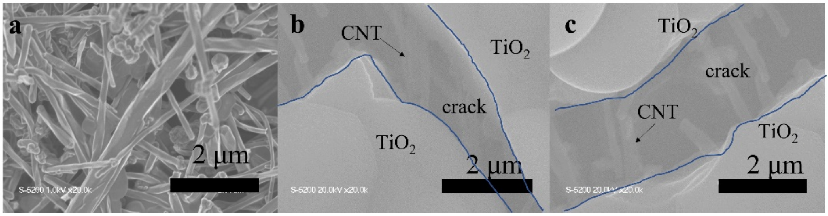
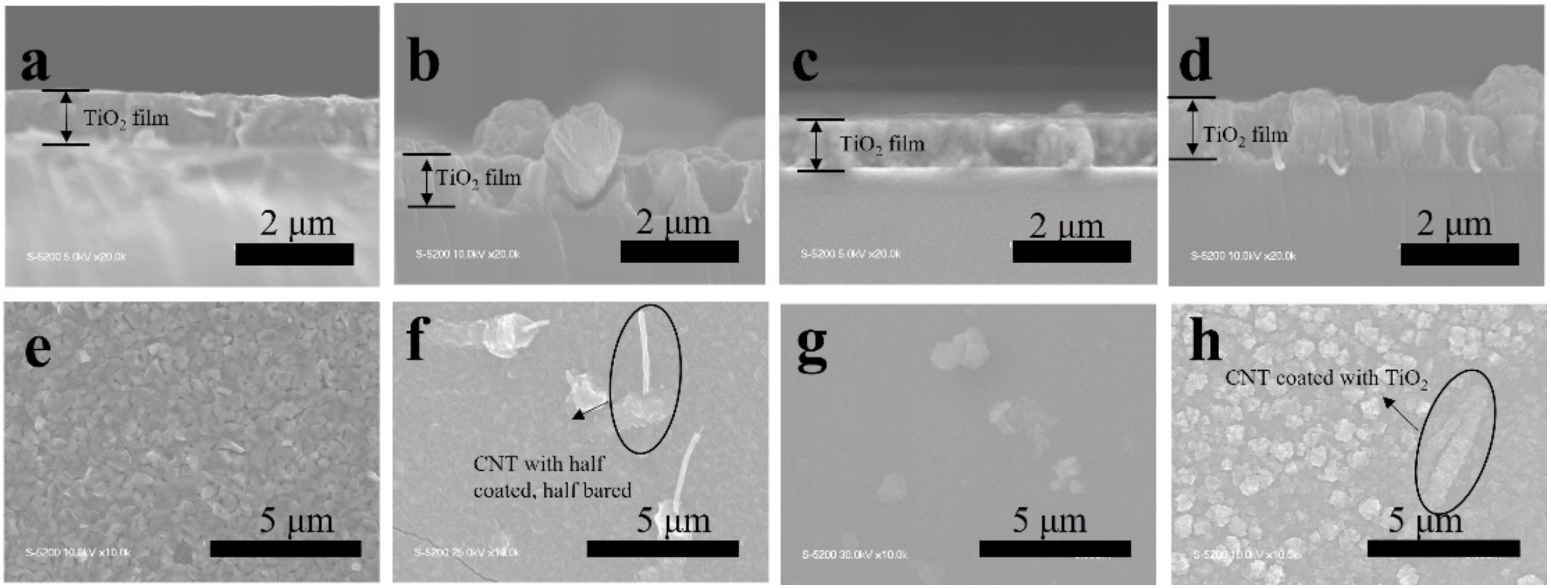
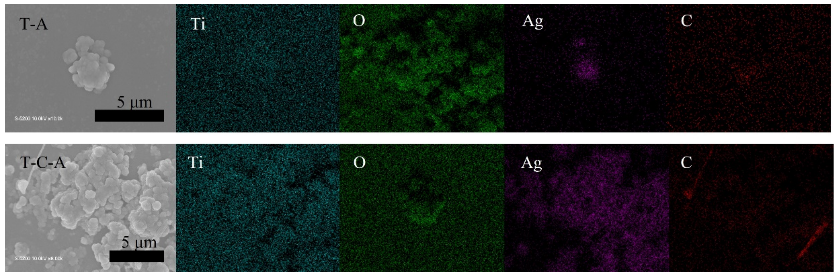
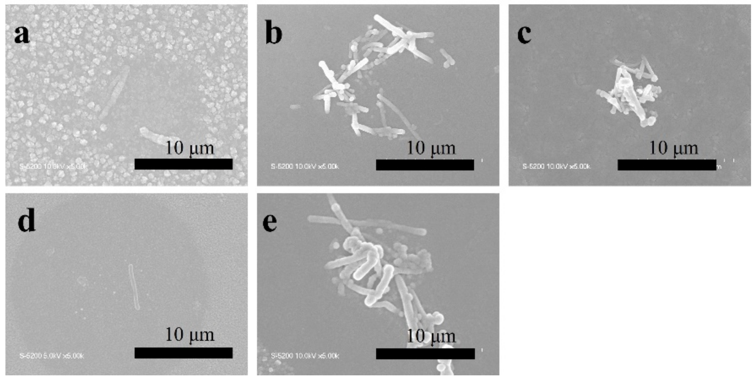
The TiO2, TiO2-CNT, TiO2-Ag, and TiO2-CNT-Ag films were generated by supplying only TTIP, a TTIP and 0.25 wt% CNT suspension, a TTIP and 0.1 wt% Ag suspension, and TTIP and CNT/Ag mixed suspensions (0.25 wt%/0.1 wt%). The corresponding products are denoted as T, T-C, T-A, and T-C-A0, respectively. The morphology of the CNTs is shown in Figure 1a. Figure 1b,c shows the scanning electron microscopy (SEM) images of the prepared T-C films containing cracks. The cracks sometimes appear on the periphery of the annealed film surface, which could be attributed to the heat treatment. The CNTs are exposed, confirming their successful incorporation into the film. Further, the morphologies of the prepared T, T-C, T-A, and T-C-A films are shown in Figure 2. Figure 2a–d show the cross-sectional morphologies of the films, which are apparently dense with a quasi-uniform thickness of approximately 1 μm. The addition of CNTs and Ag does not affect the film thickness. Compared to the T films, the CNTs are attached to TiO2 on the surfaces of the T-C and T-C-A0 films (Figure 2b,d). Only a few CNTs are observed, which can be attributed to the effective dispersion of the CNT suspension during deposition. However, the presence of Ag nanoparticles is not confirmed in the T-A and T-C-A0 (Figure 2c,d) films. The cross-sectional images of the TiO2 film show that it consists of large columnar grains. This leads to the formation of a relative regular surface, as shown in Figure 2e. However, with the supply of CNTs and Ag particles, some parts of the film surface become irregular, like the strip structure in Figure 2f, large aggregate particles in Figure 2g, and both phenomena in Figure 2e. The use of additives may lead to the growth of a core-shell structure, which results in the deposition of an irregular structure. In addition, we performed element mapping of the irregular structure that appeared in the other samples prepared under the same conditions (Figure 3). The results confirmed the presence and distribution of Ti, O, Ag, and C. The aggregated particles consisted of Ag and TiO2, and the strip structures consisted of CNT and TiO2. Thus, the results, confirmed that TiO2 was embedded with CNTs and Ag nanoparticles. Furthermore, the influence of different concentrations of the CNT/Ag mixed suspensions, such as 0.25 wt%/0.05 wt%, 0.25 wt%/0.01 wt%, 0.01 wt%/0.1 wt%, and 0.5 wt%/0.1 wt% concentrations, on the T-C-A films surface was investigated. The products were denoted as T-C-A1, T-C-A2, T-C-A3, and T-C-A4, respectively. The SEM images of these films are shown in Figure 4. From the surface structure observations, the amount of CNTs appears to be strongly influenced by the concentration of the mixed suspension. However, considering that more CNTs were embedded into the films (Figure 1), it was difficult to define the amount of CNTs based on the SEM images. In addition, it was challenging to define the morphology of the Ag particles in all the T-C-A films, which may be due to the existence of the embedded structure and the small size of Ag particles.
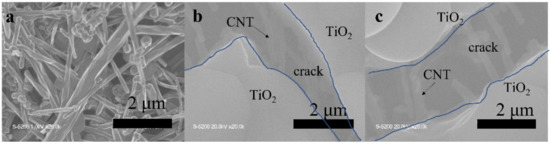
Figure 1.
Scanning electron microscopy (SEM) images of: (a) CNTs and (b) and (c) prepared T-C film containing cracks.

Figure 2.
SEM images of the prepared films. Cross-sectional morphologies of (a) T, (b) T-C, (c) T-A, and (d) T-C-A0. Surface morphologies of (e) T, (f) T-C, (g) T-A, and (h) T-C-A0.
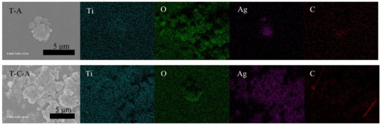
Figure 3.
Elemental mapping of T-A and T-C-A.

Figure 4.
SEM images of T-C-A films deposited using different concentrations of CNT/Ag mixed suspensions: (a) T-C-A0 (0.25 wt%/0.1 wt%), (b) T-C-A1 (0.25 wt%/0.05 wt%), (c) T-C-A2 (0.25 wt%/0.01 wt%), (d) T-C-A3 (0.01 wt%/0.1 wt%), and (e) T-C-A4 (0.5 wt%/0.1 wt%).
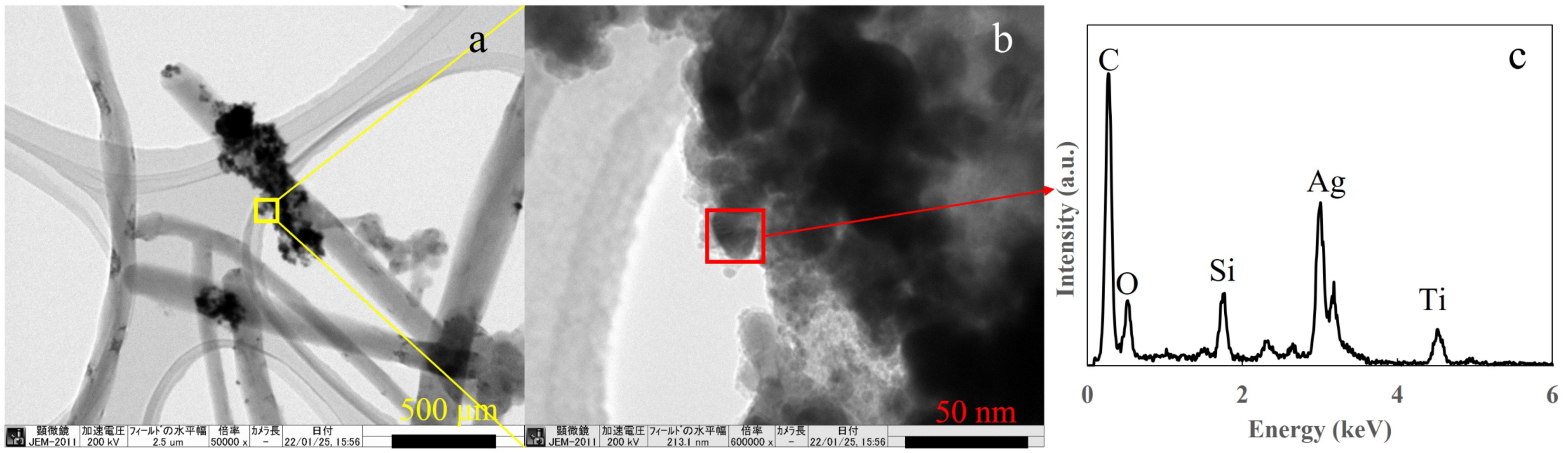
Next, transmission electron microscopy energy dispersive X-ray (TEM-EDS) spectroscopy was performed to confirm the presence of Ag in the prepared T-C-A0 film, which was selected as a representative sample. The observed sample was scratched off from the films and collected by a micro grid, therefore, the original structure was not maintained. Figure 5a depicts the TiO2 and Ag particles appeared to be attached to the CNT surface. However, the CNTs were embedded in the TiO2 film, as shown in Figure 1. Figure 5b shows a magnified version of the area in the yellow square in Figure 5a, confirming that the TiO2 and Ag nanoparticles are aggregated. Further, the EDS analysis of the area in the red square in Figure 5b proves the presence of Ag in the film.
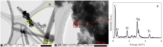
Figure 5.
Transmission electron microscopy (TEM) images of the prepared T-C-A0 film: (a) CNTs with Ag and TiO2 particles attached, (b) magnified version of the area in the yellow square in (a), and (c) energy dispersive X-ray spectroscopy (EDS) results corresponding to the red square in (b).
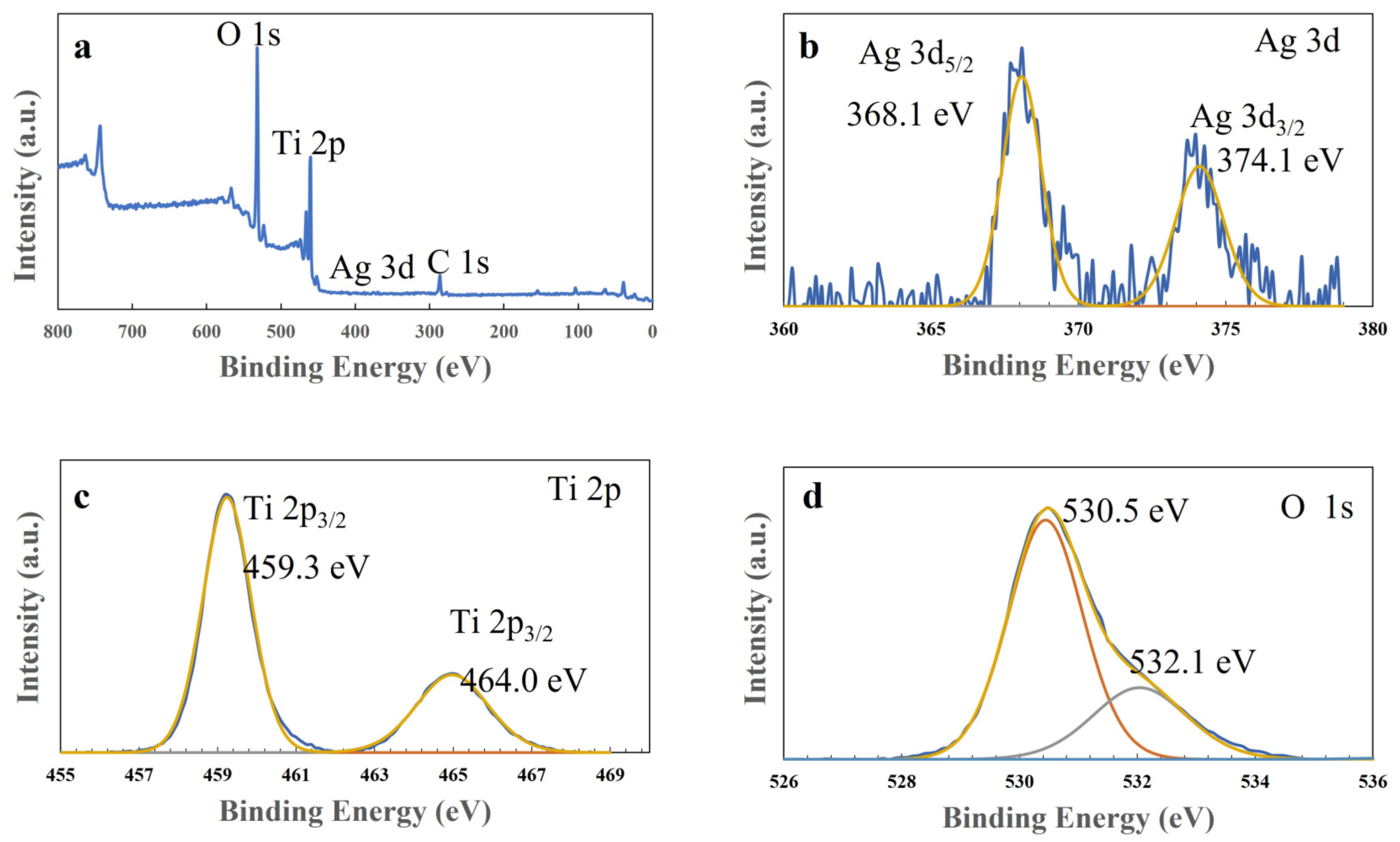
Next, X-ray photoelectron spectroscopy (XPS) measurements were performed to examine the composite spices and states in the T-C-A0 film, and the results are presented in Figure 6. The peaks corresponding to Ti 2P, Ag 3d, and O 1s are observed in the wide spectrum of this film (Figure 6a). Figure 6b illustrates the typical Ti 2p spectrum, with Ti 2p3/2 at 459.0 eV and Ti 2p1/2 at 464.7 eV. Figure 6c provides evidence of the presence of metallic Ag, with Ag 3d5/2 at 368.2 eV and Ag 3d3/2 at 374.1 eV. In addition, the two decomposed peaks from the O 1s profile correspond to the lattice oxygen in TiO2 (530.5 eV) and absorbed H2O (532.1 eV), respectively.
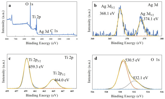
Figure 6.
X-ray photoelectron spectra of the T-C-A0 film: (a) survey, (b) Ag 3d, (c) Ti 2p, and (d) O 1s spectra.
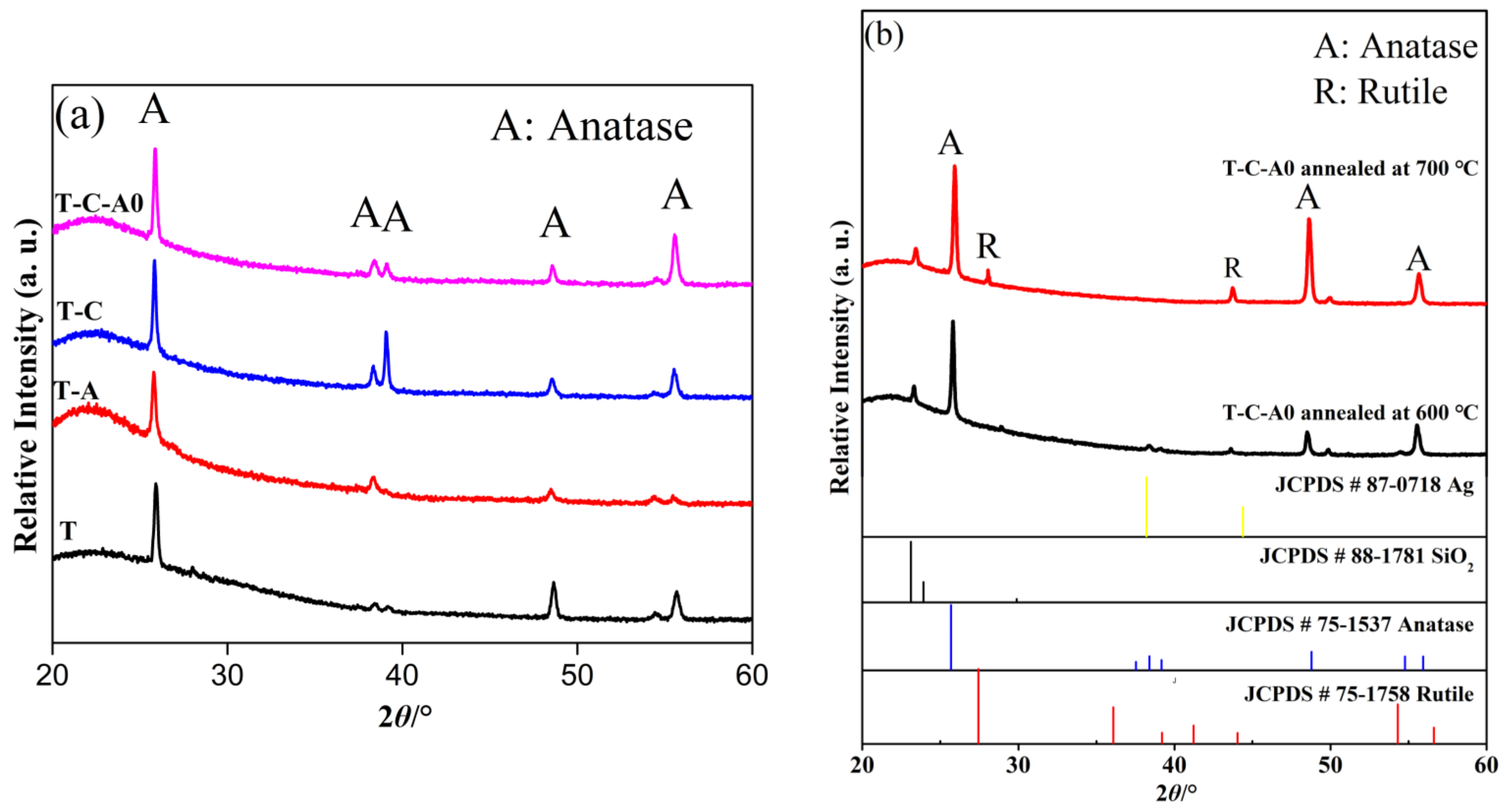
Figure 7a shows the X-ray diffraction (XRD) patterns of the T, T-C, T-A, and T-C-A0 films. The diffraction peaks marked with “A” correspond to the (101), (004), (112), (200), and (211) planes of anatase, indicating that the developed products existed in an anatase state. There is no peak corresponding to Ag nanoparticles in the patterns of the T-C-A0 and T-A films, which may be because of the low content of Ag nanoparticles in these films. Therefore, the major characteristic peak of Ag at 38.2° (111) overlaps with the characteristic peaks of TiO2 [22]. The same phenomenon occurs for the CNTs. The diffraction peak of CNTs at 25.9° is attributed to anatase TiO2. This peak shielded the CNTs at 26.1°, which is not observed in the XRD patterns of the T-C and T-C-A0 samples, suggesting that the film contained a low amount of CNTs compared to TiO2 [32].

Figure 7.
X-ray diffraction (XRD) patterns of (a) T and T-composite films and (b) T-C-A0 films annealed at different temperatures.
Generally, the abovementioned phase transformation is initiated by annealing at ~600 °C. However, we obtained the only anatase when the samples were annealed at 600 °C. When the annealing temperature was increased to 700 °C, films with an anatase–rutile mixed phase were obtained. The XRD analysis of the films annealed at different temperature are presented in Figure 7b, JCPDS cards of Ag, SiO2, anatase and rutile were used as the reference. Noticeably, only the anatase phase is evident for the T-C-A0 film annealed at 600 °C, and the peak of the rutile phase appears upon annealing at 700 °C. The phase transfer occurs between 600 and 700 °C. This result agrees well with previous findings [33].
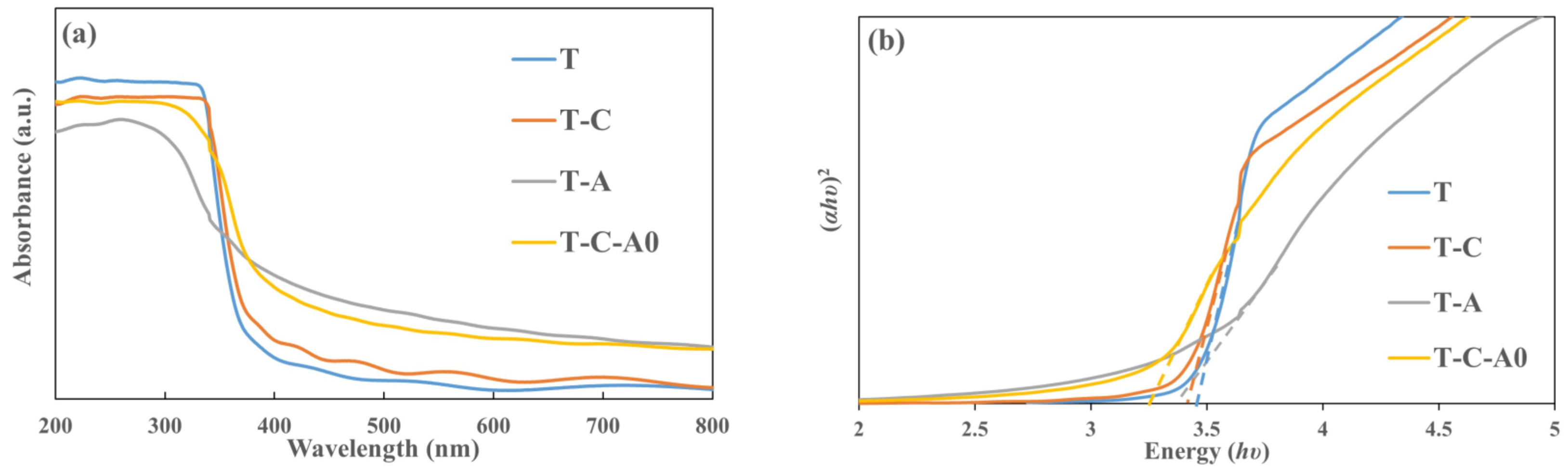
Figure 8a shows the absorption spectra of the T, T-C, T-A, and T-C-A0 films. For all of the films, the absorption increased sharply below 400 nm, probably due to the intrinsic band gap absorption of TiO2 [34]. Compared with the T film, the absorption thresholds of the T-C, T-A, and T-C-A films extend to the longer wavelength range. This behavior can be attributed to the photosensitizing effect of CNTs and the local surface plasmon resonance (LSPR) effect of the Ag particles [35]. Furthermore, the energy level was presumably aligned in the composite film by the introduction of CNTs and Ag, which can be attributed to the charge transmission among the TiO2, Ag, and CNTs [36]. The band gap energy can be estimated by employing the Tauc relation: αhυ = B (hυ − Eg)1/2, where α is the absorption coefficient, hυ is the photon energy, Eg is the optical band gap, and B is the absorption constant for direct transitions. Figure 8b shows the plot of (αhυ)2 versus photoenergy (hυ), where the intercept of the tangent to the plot corresponds to the bandgap. The bandgap of the T film is 3.47 eV; however, it decreases to 3.39 eV for the T-C film, 3.31 eV for the T-A film, and 3.22 eV for the T-C-A film.
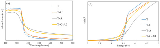
Figure 8.
Optical properties of the T and T-composite film: (a) absorbance spectra and (b) (αhυ)2 versus photon energy (hυ) plot of the prepared films.
The ratio of Ag/Ti in the film was confirmed by inductivity coupled plasma optical emission spectrometry (ICP-OES) analysis. The results are presented in Table 1. The units of CNT/Ag (wt%/wt%) suspensions refer to the raw materials (relative values) and correspond to the conditions when deposit films were deposited. Ag/Ti (mg/mg) refer to the results of the ICP-OES analysis and corresponds to the content of the film (absolute values (mass)). Ag nanoparticles were present in all of the T-C-A films. However, the Ag/Ti ratio decreases with decreasing Ag concentration. This result indicates that the Ag content in the films was influenced by the Ag concentration.

Table 1.
Elemental analysis of the T-C-A film using inductivity coupled plasma optical emission spectrometry.
2.2. Photocatalytic Activity of the Films
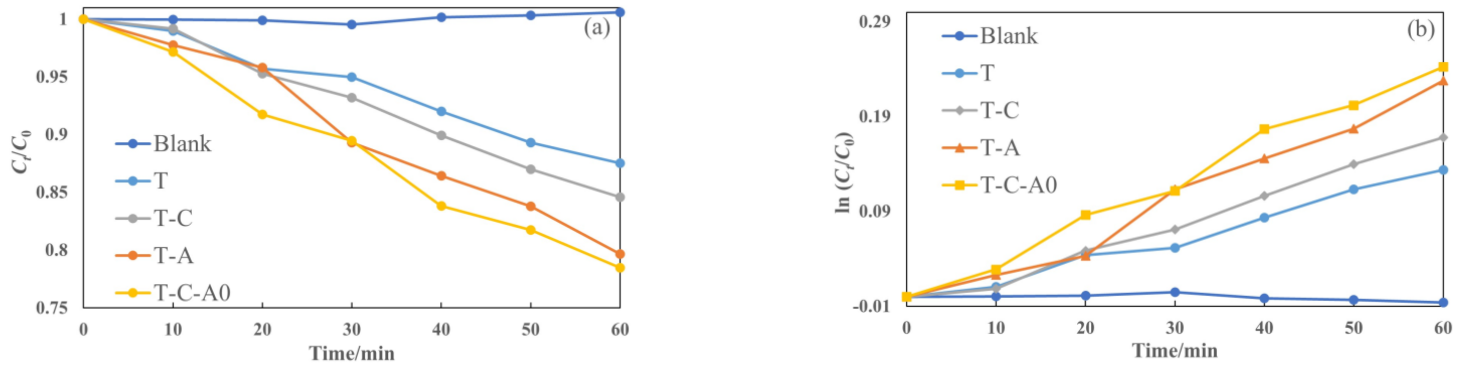
Figure 9 illustrates the photocatalytic degradation of aqueous rhodamine 6G by different films under simulated solar light. The films used in this section were annealed at 600 °C. The plot of Ct/C0 versus the specified irradiation time (t) for different films is presented in Figure 9a. Furthermore, we prepared the ln (Ct/C0) versus t plot (Figure 9b) to obtain the corresponding rate constant k from the slope of the fitting curve (Figure 9c). The photocatalytic activity of the film under simulated solar light decreased in the following order: T-C-A0 > T-A > T-C > T. Compared with the T film deposited by PECVD, the composite films performed better. Furthermore, the k of the prepared T-C-A0 film is approximately 1.8 times higher than that of the prepared T film.

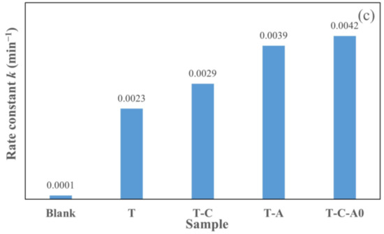
Figure 9.
Photocatalytic activity for the degradation of rhodamine 6G by different films under simulated solar light: (a) degradation with respect to time, (b) ln (Ct/C0) versus to time plot and (c) rate constants degradation for various samples.
In addition, Figure 10a presents the plot of Ct/C0 as a function of irradiation time for the T-C-A0 films annealed at different temperatures. We also plotted ln (Ct/C0) against t (Figure 10b) to obtain the corresponding rate constant k from the slope of the fitting curve (Figure 10c). The efficiency of the T-C-A0 films annealed at 700 °C for rhodamine 6G degradation is higher than that of the T-C-A0 films annealed at 600 °C, which can be attributed to the phase transfer of the crystalline phase at different annealing temperatures.
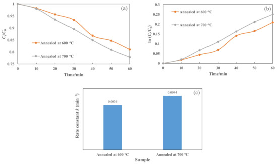
Figure 10.
Photocatalytic degradation of rhodamine 6G by T-C-A films annealed at different temperatures: (a) degradation with respect to time, (b) ln (Ct/C0) versus to time plot, and (c) corresponding rate constants of degradation for samples.
To the best of our knowledge, other researchers have also estimated the photocatalytic activity based on the rate constant. Soltanieh et al. prepared a TiO2/Ag0@MWCNTs composite with rate constant of 0.07675 min−1 [37], which is higher than that of their prepared TiO2/Ag binary structure. Wang et al. illustrated an Ag-CNT/TiO2 composite with a rate constant 0.03052 min−1 [21], which is higher than that of their prepared CNT/TiO2 binary structure. Numerous factors affect the photocatalytic activity, such as the concentration of dyes, power of the irradiation light, and morphology of the catalyst. Thus, it is difficult to compare the activities of the catalysts prepared in different studies. Nevertheless, we proved that the fabricated ternary composites show a higher rate constant than that of fabricated binary composite (TiO2-CNT and TiO2-Ag). Therefore, the developed process has significant potential to improve the performance of photocatalysts.
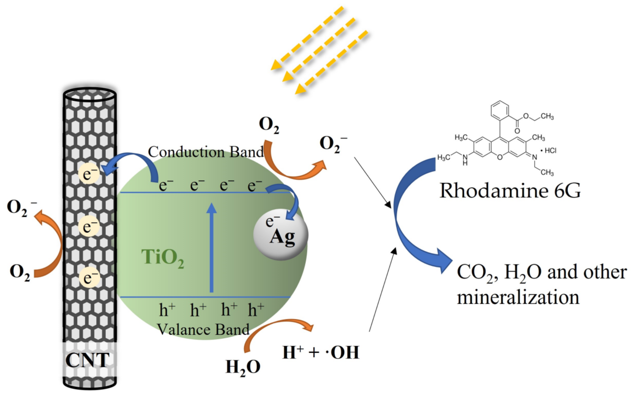
These results confirm that the photocatalytic activity of TiO2 is significantly enhanced by embedding CNTs and Ag particles into the TiO2 film. In addition, the ternary composites (T-C-A) show higher photocatalytic activity than binary structure films (T-C and T-A). Thus, we believe that the photoreaction system in this study could not be simply defined as two binary systems. However, we could not determine the detailed structure of this system during photoreaction. Moreover, the photocatalytic mechanisms are so complex that defining them only by film structure is insufficient. Hence, we assume the possible mechanism for the ternary system during photoreaction. In general, electrons are generated by the light irradiation of Ag nanoparticles due to the LSPR effect. These photoexcited electrons can be transferred to the conduction band of TiO2 through the Schottky barrier formed at the Ag–TiO2 interface [18]. Simultaneously, TiO2 can act as a photosensitizer, where the valence band electrons can be excited to a new sub-bandgap state that is formed by the TiO2-CNT-Ag ternary structure [38]. In addition, CNTs act as electron acceptors, and the electrons on TiO2 and Ag can also be transferred to the CNTs, which reduces electron-hole recombination. Thus, charge carriers contribute to the formation of active species (O2−, ·OH), thereby enhancing the photocatalytic activity [39]. We propose that TiO2 acts as the main photosensitizer under solar light irradiation due to the special structure of the ternary films and that the activated electrons can easily be transferred to the CNTs and Ag, reducing the recombination of electron–hole pairs, as shown in Figure 11.

Figure 11.
Possible schematic explaining the photocatalytic activity of the T-C-A ternary film.
3. Experimental
3.1. Experimental Process
The CNT suspensions (0.5 wt%) were prepared using 0.5 g of CNTs (Sigma-Aldrich, St. Louis, MO, USA, diameter: 110–170 nm and length: 5–9 μm) dispersed in 95 mL of deionized water with Triton X-100 as the dispersant. The Ag nanoparticle suspensions (0.1 wt%) were synthesized via co-precipitation [40]. Subsequently, 0.18 g of AgNO3 (Nacalai Tesque, Inc., Tokyo, Japan) was dissolved into 100 mL of deionized water, and 2 mL of 0.01 g/mL of trisodium citric acid (Wako Pure Chemical Industries, Ltd., Osaka, Japan) aqueous solution was added. The mixture was then stirred at 100 °C for 1 h and cooled to ~25 °C. A solid suspension for spraying was prepared by mixing water, the CNT suspension, and the Ag nanoparticle suspension with a certain concentration.
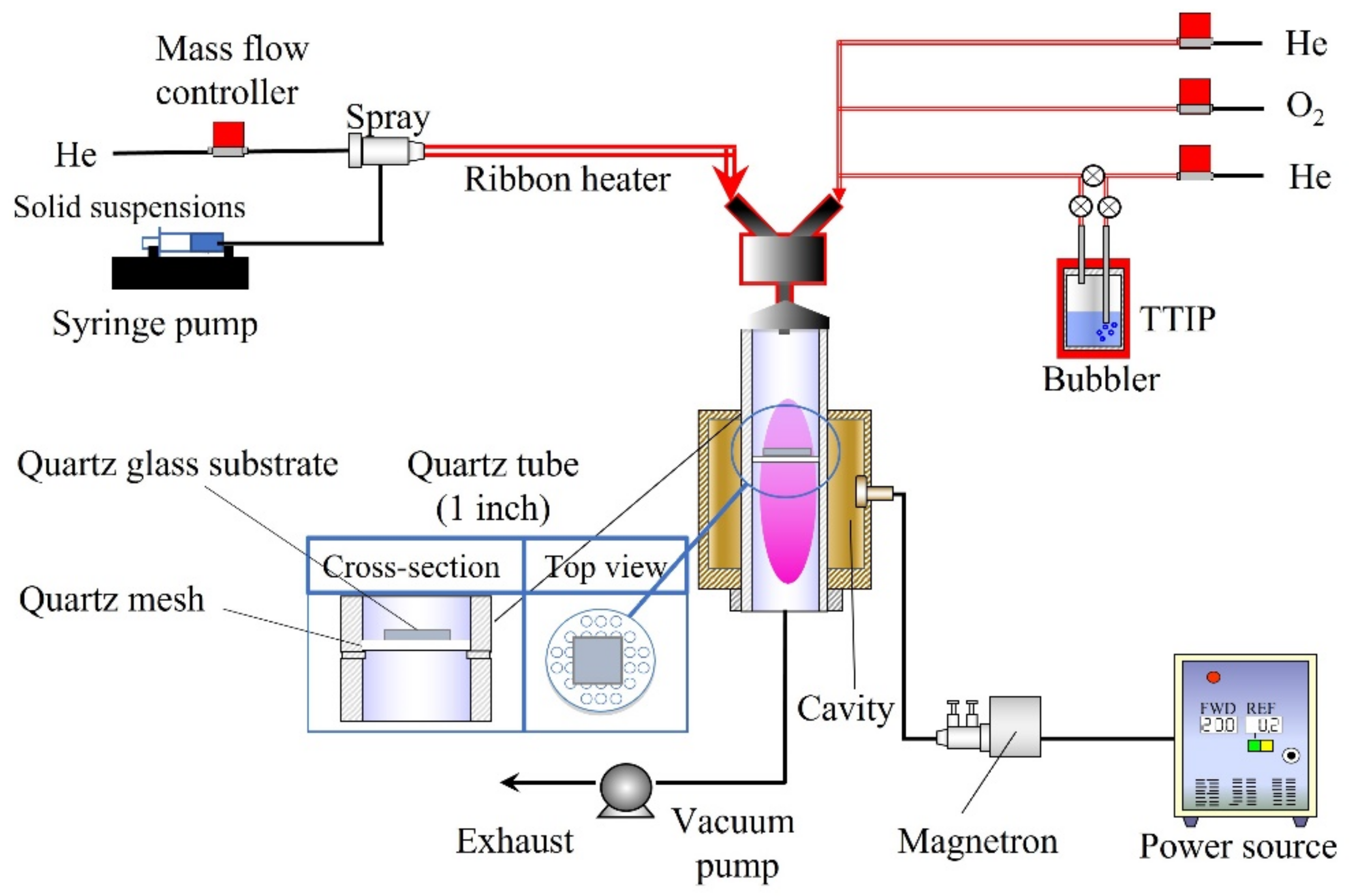
Figure 12 shows the experimental setup consisting of different feeding systems [15,31]. A solid suspension (10 mL) was supplied by a syringe pump (YSP-301, YMC. Co., Ltd., Kyoto, Japan) with a capillary tube. A two-fluid nozzle was used to spray the solid suspension, with He gas flowing at a rate of 1000 sccm. The transport tube was preheated using a ribbon heater to dry the solid suspension. The obtained aerosol particles of CNT/Ag were supplied to the plasma cavity. On the other hand, TTIP (Tokyo Chemical Industry Co., Ltd., Tokyo, Japan) was vaporized in a bubbler (45 °C) with He gas at a flow rate of 50 sccm. Meanwhile, O2 gas with a flow rate of 50 sccm and He gas with a flow rate of 400 sccm were employed to transfer the vaporized TTIP. The quartz tube (inner diameter: 25.4 mm; length: 300 mm) was wrapped and supported by a cavity. Furthermore, we designed a recessed part in the middle of the quartz tube to place a quartz mesh and hold a glass substrate, on which the films could be deposited. The plasma was produced by 190 W microwaves (2.45 GHz) in a quartz tube. A vacuum pump (Pascal 2025C1, Pfeiffer Vacuum, Inc., Asslar, Germany) was used to maintain all the equipment under vacuum pressure before feeding and at ~6 kPa after the materials were fed. The films were deposited on a quartz glass plate (1 × 1 cm) through the simultaneous feeding of the TTIP and CNT/Ag suspensions for 15 min. The obtained films were annealed at 600 °C and 700 °C in an N2 atmosphere.
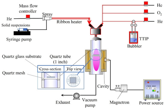
Figure 12.
Experimental setup for PECVD.
3.2. Film Characterization
The morphology of the films was analyzed by SEM (S-5200, Hitachi High Technologies, Tokyo, Japan) and TEM (JEM-2010, JEOL, Tokyo, Japan), in conjunction with EDS (JED-2300T, JEOL, Tokyo, Japan). The elemental analysis was performed by XPS (ESCA-3400, SHIMADAZU, Kyoto, Japan). The crystal structures of the films were investigated by XRD (RINT-2100, Rigaku, Tokyo, Japan), using Cu-Kα radiation (λ = 1.5406 Å). The UV–Vis spectra of the films were recorded using a V-650 UV–Vis spectrophotometer (Jasco, Tokyo, Japan).
Further, the elemental analysis of the films was conducted by employing an ICP-OES instrument (SPS3000, Hitachi High Technologies, Tokyo, Japan). Each film was placed in a polypropylene sample tube and immersed in 1 mL of ethanol. Ethanol was used as a lubricant and collector for the scraped film powder. A micro grinder equipped with an electroplated diamond burr was used to scrape the film off the substrate. The obtained powder was dried and dissolved in HF. Excess HF was neutralized by H3BO4, and the solvents were then filtered and used for ICP-OES analysis.
3.3. Photocatalytic Activity
To investigate the photocatalytic activities of the films, the degradation of rhodamine 6G by the films under simulated solar-light irradiation was evaluated. The spectrum of the light used to activate the films is recorded by spectro multi-channel photo detector (MCPD-3000, Otsuka Electronics, Osaka, Japan), and the result is shown in Figure 13. Firstly, the films were immersed in 3 mL of a rhodamine 6G aqueous solution (5 mg/L), which was held in the cuvette cell and left in the dark for 30 min to reach adsorption equilibrium. Subsequently, the catalytic process was activated through irradiation with simulated solar light (300–800 nm). Using the equation for the absorbance and concentration of rhodamine 6G, the maximum absorbances of rhodamine 6G at different times were observed and converted into concentrations of rhodamine 6G. The concentrations before and after irradiation were determined through UV–Vis spectrophotometry (V-650, Jasco, Tokyo, Japan) every 10 min. Furthermore, the degradation efficiency was determined by Ct/C0, and the rate constant k was calculated as follows:
where C0 and Ct represent the concentrations of rhodamine 6G before and after irradiation, respectively, and t is the irradiation time.
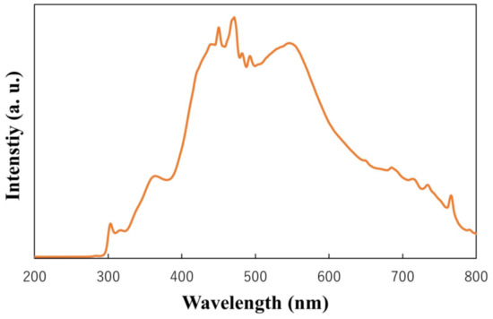
Figure 13.
Light spectrum used to activate the films.
4. Conclusions
In this study, a T-C-A ternary composite film was successfully prepared using a novel and simple process with relatively good coverage. The XRD spectrum revealed that the structure of T-C-A had a pure anatase phase after annealing at 600 °C and an anatase–rutile mixed phase after annealing at 700 °C. The SEM images exhibited good coverage with the CNT embedded structure of the T-C-A film, and the thickness was approximately 1 μm. The TEM-EDS images indicated the presence of Ag. The XPS analysis proved that Ag existed in the metallic state. The UV–Vis spectrum confirmed that the absorbance of T-C-A extended to longer wavelength. The ICP-OES results indicated the presence of Ag. Moreover, the photocatalytic activity of the prepared T-C-A film was approximately 1.8 times higher than that of the prepared T film. The expected ternary structure and photocatalytic ability of T-C-A were determined using PECVD. We believe that the investigated process has immense potential for use in the preparation of films with different materials.
Author Contributions
Conceptualization, M.S.; methodology, J.L. and K.T.; formal analysis, J.L.; writing—J.L.; writing—Review and editing, J.L., M.S. and M.K.; supervision: M.S.; funding acquisition, M.S. All authors have read and agreed to the published version of the manuscript.
Funding
This work is partly supported by Japan Society for the Promotion of Science KAKENHI grant numbers 21K04750.
Data Availability Statement
Data are contained within the article.
Acknowledgments
We would like to thank M. Maeda for assistance with the TEM analysis.
Conflicts of Interest
There are no conflict of interest.
References
- Zhu, X.; Lin, Y.; San Martin, J.; Sun, Y.; Zhu, D.; Yan, Y. Lead halide perovskites for photocatalytic organic synthesis. Nat. Commun. 2019, 10, 2843. [Google Scholar] [CrossRef] [PubMed]
- Tobaldi, D.M.; Dvoranova, D.; Lajaunie, L.; Rozman, N.; Figueiredo, B.; Seabra, M.P.; Skapin, A.S.; Calvino, J.J.; Brezova, V.; Labrincha, J.A. Graphene-TiO2 hybrids for photocatalytic aided removal of VOCs and nitrogen oxides from outdoor environment. Chem. Eng. J. 2021, 405, 126651. [Google Scholar] [CrossRef] [PubMed]
- Yadav, A.A.; Hunge, Y.M.; Kulkarni, S.B. Synthesis of multifunctional FeCo2O4 electrode using ultrasonic treatment for photocatalysis and energy storage applications. Ultrason. Sonochem. 2019, 58, 104663. [Google Scholar] [CrossRef] [PubMed]
- Wang, Z.; Lin, Z.; Shen, S.; Zhong, W.; Cao, S. Advances in designing heterojunction photocatalytic materials. Chin. J. Catal. 2021, 42, 710–730. [Google Scholar] [CrossRef]
- He, S.; Rong, Q.; Niu, H.; Cai, Y. Platform for molecular-material dual regulation: A direct Z-scheme MOF/COF heterojunction with enhanced visible-light photocatalytic activity. Appl. Catal. B Environ. 2019, 247, 49–56. [Google Scholar] [CrossRef]
- Zhu, Y.; Liu, Y.; Ai, Q.; Gao, G.; Yuan, L.; Fang, Q.; Tian, X.; Zhang, X.; Egap, E.; Ajayan, P.M.; et al. In Situ Synthesis of Lead-Free Halide Perovskite–COF Nanocomposites as Photocatalysts for Photoinduced Polymerization in Both Organic and Aqueous Phases. ACS Mater. Lett. 2022, 4, 464–471. [Google Scholar] [CrossRef]
- Hieu, V.Q.; Phung, T.K.; Nguyen, T.-Q.; Khan, A.; Doan, V.D.; Tran, V.A.; Le, V.T. Photocatalytic degradation of methyl orange dye by Ti3C2–TiO2 heterojunction under solar light. Chemosphere 2021, 276, 130154. [Google Scholar] [CrossRef]
- Hao, R.; Wang, G.; Tang, H.; Sun, L.; Xu, C.; Han, D. Template-free preparation of macro/mesoporous g-C3N4/TiO2 heterojunction photocatalysts with enhanced visible light photocatalytic activity. Appl. Catal. B Environ. 2016, 187, 47–58. [Google Scholar] [CrossRef]
- Sobczyk-Guzenda, A.; Owczarek, S.; Szymanowski, H.; Volesky, L.; Walkowiak, B.; Miszczak, S.; Gazicki-Lipman, M. Iron doped thin TiO2 films synthesized with the RF PECVD method. Ceram. Int. 2015, 41, 7496–7500. [Google Scholar] [CrossRef]
- Li, D.; Bulou, S.; Gautier, N.; Elisabeth, S.; Goullet, A.; Richard-Plouet, M.; Choquet, P.; Granier, A. Nanostructure and photocatalytic properties of TiO2 films deposited at low temperature by pulsed PECVD. Appl. Surf. Sci. 2019, 466, 63–69. [Google Scholar] [CrossRef]
- Varshney, G.; Kanel, S.R.; Kempisty, D.M.; Varshney, V.; Agrawal, A.; Sahle-Demessie, E.; Varma, R.S.; Nadagouda, M.N. Nanoscale TiO2 films and their application in remediation of organic pollutants. Coord. Chem. Rev. 2016, 306, 43–64. [Google Scholar] [CrossRef]
- Rapsomanikis, A.; Apostolopoulou, A.; Stathatos, E.; Lianos, P. Cerium-modified TiO2 nanocrystalline films for visible light photocatalytic activity. J. Photochem. Photobiol. A Chem. 2014, 280, 46–53. [Google Scholar] [CrossRef]
- Lee, M.S.; Hong, S.S.; Mohseni, M. Synthesis of photocatalytic nanosized TiO2-Ag particles with sol-gel method using reduction agent. J. Mol. Catal. A Chem. 2005, 242, 135–140. [Google Scholar] [CrossRef]
- Yogi, C.; Kojima, K.; Wada, N.; Tokumoto, H.; Takai, T.; Mizoguchi, T.; Tamiaki, H. Photocatalytic degradation of methylene blue by TiO2 film and Au particles-TiO2 composite film. Thin Solid Films 2008, 516, 5881–5884. [Google Scholar] [CrossRef]
- Lang, J.; Takahashi, K.; Kubo, M.; Shimada, M. Ag-Doped TiO2 Composite Films Prepared Using Aerosol-Assisted, Plasma-Enhanced Chemical Vapor Deposition. Catalysts 2022, 12, 365. [Google Scholar] [CrossRef]
- Lu, G.; Wang, X.; Wang, Y.; Shi, G.; Xie, X.; Sun, J. Anti-oxidative microstructure design of ultra-stable N-TiO2 composite for the gaseous photodegradation reactions. Chem. Eng. J. 2021, 408, 127257. [Google Scholar] [CrossRef]
- Chen, M.; Zhang, F.; Oh, W. Synthesis, characterization, and photocatalytic analysis of CNT/TiO2 composites derived from MWCNTs and titanium sources. New Carbon Mater. 2009, 24, 159–166. [Google Scholar] [CrossRef]
- Chaudhary, D.; Singh, S.; Vankar, V.D.; Khare, N. A ternary Ag/TiO2/CNT photoanode for efficient photoelectrochemical water splitting under visible light irradiation. Int. J. Hydrog. Energy 2017, 42, 7826–7835. [Google Scholar] [CrossRef]
- Zhou, W.; Pan, K.; Qu, Y.; Sun, F.F.; Tian, C.G.; Ren, Z.Y.; Tian, G.H.; Fu, H.G. Photodegradation of organic contamination in wastewaters by bonding TiO2/single-walled carbon nanotube composites with enhanced photocatalytic activity. Chemosphere 2010, 81, 555–561. [Google Scholar] [CrossRef]
- Banerjee, S.; Benjwal, P.; Singh, M.; Kar, K.K. Graphene oxide (rGO)-metal oxide (TiO2/Fe3O4) based nanocomposites for the removal of methylene blue. Appl. Surf. Sci. 2018, 439, 560–568. [Google Scholar] [CrossRef]
- Wang, S.; Gong, Q.M.; Zhu, Y.F.; Liang, J. Preparation and photocatalytic properties of silver nanoparticles loaded on CNTs/TiO2 composite. Appl. Surf. Sci. 2009, 255, 8063–8066. [Google Scholar] [CrossRef]
- Koo, Y.; Littlejohn, G.; Collins, B.; Yun, Y.; Shanov, V.N.; Schulz, M.; Pai, D.; Sankar, J. Synthesis and characterization of Ag–TiO2–CNT nanoparticle composites with high photocatalytic activity under artificial light. Compos. Part. B Eng. 2014, 57, 105–111. [Google Scholar] [CrossRef]
- Arabatzis, I.M.; Stergiopoulos, T.; Bernard, M.C.; Labou, D.; Neophytides, S.G.; Falaras, P. Silver-modified titanium dioxide thin films for efficient photodegradation of methyl orange. Appl. Catal. B Environ. 2003, 42, 187–201. [Google Scholar] [CrossRef]
- Akhavan, O. Lasting antibacterial activities of Ag-TiO2/Ag/a-TiO2 nanocomposite thin film photocatalysts under solar light irradiation. J. Colloid Interface Sci. 2009, 336, 117–124. [Google Scholar] [CrossRef] [PubMed]
- Liu, Y.; Wang, X.L.; Yang, F.; Yang, X.R. Excellent antimicrobial properties of mesoporous anatase TiO2 and Ag/TiO2 composite films. Microporous Mesoporous Mater. 2008, 114, 431–439. [Google Scholar] [CrossRef]
- Suda, Y.; Kawasaki, H.; Ueda, T.; Ohshima, T. Preparation of high quality nitrogen doped TiO2 thin film as a photocatalyst using a pulsed laser deposition method. Thin Solid Films 2004, 453, 162–166. [Google Scholar] [CrossRef]
- Liu, Y.; Xu, C.; Feng, Z.D. Characteristics and anticorrosion performance of Fe-doped TiO2 films by liquid phase deposition method. Appl. Surf. Sci. 2014, 314, 392–399. [Google Scholar] [CrossRef]
- Lim, S.; Huang, N.M.; Lim, H.N.; Mazhar, M. Surface Modification of Aerosol-Assisted CVD Produced TiO2 Thin Film for Dye Sensitised Solar Cell. Int. J. Photoenergy 2014, 2014, 1–12. [Google Scholar] [CrossRef]
- Ebrahimi, I.; Gashti, M.P. Polypyrrole-MWCNT-Ag composites for electromagnetic shielding: Comparison between chemical deposition and UV-reduction approaches. J. Phys. Chem. Solids 2018, 118, 80–87. [Google Scholar] [CrossRef]
- Alimohammadi, F.; Gashti, M.P.; Shamei, A.; Kiumarsi, A. Deposition of silver nanoparticles on carbon nanotube by chemical reduction method: Evaluation of surface, thermal and optical properties. Superlattices Microstruct. 2012, 52, 50–62. [Google Scholar] [CrossRef]
- Kubo, M.; Taguchi, T.; Shimada, M. Preparation of nanoparticle-embedded thin films by simultaneous feeding of gaseous and solid raw materials in plasma-enhanced chemical vapor deposition process. Thin Solid Films 2017, 632, 55–65. [Google Scholar] [CrossRef]
- Askari, M.B.; Banizi, Z.T.; Seifi, M.; Dehaghi, S.B.; Veisi, P. Synthesis of TiO2 nanoparticles and decorated multi-wall carbon nanotube (MWCNT) with anatase TiO2 nanoparticles and study of optical properties and structural characterization of TiO2/MWCNT nanocomposite. Optik 2017, 149, 447–454. [Google Scholar] [CrossRef]
- Choudhury, B.; Choudhury, A. Local structure modification and phase transformation of TiO2 nanoparticles initiated by oxygen defects, grain size, and annealing temperature. Int. Nano Lett. 2013, 3, 55. [Google Scholar] [CrossRef]
- Yu, J.G.; Yu, H.G.; Cheng, B.; Zhou, M.H.; Zhao, X.J. Enhanced photocatalytic activity of TiO2 powder (P25) by hydrothermal treatment. J. Mol. Catal. A Chem. 2006, 253, 112–118. [Google Scholar] [CrossRef]
- Zhao, C.; Guo, J.; Yu, C.; Zhang, Z.; Sun, Z.; Piao, X. Fabrication of CNTs-Ag-TiO2 ternary structure for enhancing visible light photocatalytic degradation of organic dye pollutant. Mater. Chem. Phys. 2020, 248, 122873. [Google Scholar] [CrossRef]
- Aazam, E.S. Visible light photocatalytic degradation of thiophene using Ag-TiO2/multi-walled carbon nanotubes nanocomposite. Ceram. Int. 2014, 40, 6705–6711. [Google Scholar] [CrossRef]
- Soltanieh, A.M.; Khavar, A.H.C.; Ganjidoust, H.; Mahjoub, A.R.; Khazaee, Z. Plasmon-induced charge separation by Ag nanoparticles between titanium dioxide and MWCNTs for natural sunlight-driven photocatalysis. J. Iran. Chem. Soc. 2021. [Google Scholar] [CrossRef]
- De la Flor, M.P.; Camarillo, R.; Martínez, F.; Jiménez, C.; Quiles, R.; Rincón, J. Synthesis and characterization of TiO2/CNT/Pd: An effective sunlight photocatalyst for neonicotinoids degradation. J. Environ. Chem. Eng. 2021, 9, 106278. [Google Scholar] [CrossRef]
- Wang, T.; Tang, T.; Gao, Y.; Chen, Q.; Zhang, Z.; Bian, H. Hydrothermal preparation of Ag-TiO2-reduced graphene oxide ternary microspheres structure composite for enhancing photocatalytic activity. Phys. E Low-Dimens. Syst. Nanostruct. 2019, 112, 128–136. [Google Scholar] [CrossRef]
- Gaafar, M.R.; Mady, R.F.; Diab, R.G.; Shalaby, T.I. Chitosan and silver nanoparticles: Promising anti-toxoplasma agents. Exp. Parasitol. 2014, 143, 30–38. [Google Scholar] [CrossRef]


Publisher’s Note: MDPI stays neutral with regard to jurisdictional claims in published maps and institutional affiliations. |
© 2022 by the authors. Licensee MDPI, Basel, Switzerland. This article is an open access article distributed under the terms and conditions of the Creative Commons Attribution (CC BY) license (https://creativecommons.org/licenses/by/4.0/).