Article

Effects of Sintering Parameters on the Low-Temperature Densification of GDC Electrolyte Based on an Orthogonal Experiment

1
School of Mechanical Engineering, Beijing Institute of Technology, Beijing 100081, China
2
State Key Laboratory of Automotive Safety and Energy, Tsinghua University, Beijing 100084, China
*
Author to whom correspondence should be addressed.
Catalysts 2022, 12(8), 831; https://doi.org/10.3390/catal12080831
Submission received: 27 June 2022 / Revised: 19 July 2022 / Accepted: 27 July 2022 / Published: 28 July 2022
(This article belongs to the Section Catalysis for Sustainable Energy)

Abstract

:
A solid oxide fuel cell is a high-efficiency power device in hydrogen energy utilization. The durability and dynamic performance of metal-supported solid oxide fuel cells (MS-SOFCs) are superior to those of electrolyte- or electrode-supported cells, with many potential applications. Gadolinium-doped cerium (GDC) has a high oxygen ionic conductivity, making it suitable to act as the electrolyte in MS-SOFCs operating at 500–650 °C. However, the low-temperature sintering of GDC is difficult for MS-SOFCs. In this study, the factors affecting the low-temperature densification of GDC are analyzed based on an orthogonal experimental method. The shrinking rates of 16 experiments are determined. The effects of the particle diameter, pressure of the uniaxial press machine, sintering temperature, and fractions of aid and binder are estimated. The results of a range analysis indicate that the content of sintering aid has the greatest impact on the low-temperature densification of GDC, followed by the powder diameter and the uniaxial pressure. A maximum shrinking rate of 46.99% is achieved with a temperature of 1050 °C.

1. Introduction

As the requirements for clean, abundant, and sustainable energy increase continuously, fuel cell technology will become a key solution [1,2]. Among various types of fuel cells, solid oxide fuel cells (SOFCs) have a high energy efficiency and a good adaptability to different fuels [3], making them a promising technology for future power systems [4,5,6]. SOFCs with an output power of 50 kWe to 200 kWe had been developed and tested [7]. Domestic SOFC-based combined heat and power (CHP) systems have been applied widely in Japan [8]. SOFCs are also suitable for use in transport vehicles [9,10] and drones [11]. However, the working temperature of SOFCs is normally greater than 750 °C, leading to serious performance degradation during long-term operation, as well as constrains with respect to commercial applications [12].
The ionic conductivity of an electrolyte has a considerable impact on the current density of an SOFC. Yttria-stabilized zirconia (YSZ) is normally used as the electrolyte. However, its working temperature must be in the range of 750–850 °C to guarantee suitable oxygen ionic conductivity (0.01–0.1 S/cm) [13]. Although YSZ exhibits good thermal and mechanical stability of in an oxidative or reductive atmosphere, such a high operation temperature poses a considerable challenge for glass sealant [14] and accelerates the degradation of the electrolyte and other components, which is the main factor affecting the lifetime [15,16]. If the working temperature can be decreased to 500–650 °C, the requirements of sealant materials can be reduced, and the durability of SOFCs can be improved significantly. However, YSZ is not suitable for operation under such a low temperature due to its low conductivity [17,18,19,20]. The oxygen ionic conductivity of gadolinium-doped ceria (GDC) almost an order of magnitude greater than that of YSZ, making it a feasible electrolyte for medium-temperature SOFCs [21].
To reduce ohmic loss in such a system, the thickness of the electrolyte needs to be much thinner compared with that of an electrolyte-supported SOFC. Hence, electrode-supported SOFCs have been developed. For the cathode-supported cell, the activation loss is severe, and therefore, most cells adopt an anode-supported structure [22]. However, such a structure is associated with a redox issue for the anode, which is mainly caused by Ni particles, resulting in a high temperature uniformity requirement due to the fragile characteristics of ceramic materials [23]. Therefore, third-generation metal-supported SOFCs were developed to overcome these shortcomings [24,25]. Compared with an anode-supported cell, metal-supported cells have higher durability, a lower cost, and can withstand very rapid temperature variations [26]. For metal-supported SOFCs, the working temperature needs to be controlled below 700 °C to improve the antioxidation performance of the metal substrate. GDC is more suitable than YSZ at such a low working temperature due to its higher ionic conductivity. The oxygen ionic conductivity of GDC is about 0.150 S/cm at 620 °C, which is five times greater than that of YSZ [27,28].
Normally, GDC powder needs to be sintered at a high temperature of around 1400 °C to ensure a densification of more than 95%. For instance, GDC powder was sintered at 1350 °C for 2 h, and the effects of the molar ratio of fuel to oxidizer, combustion temperature of the gel, calcination temperature, and dwell time of the powder for a sol-gel preparation process were evaluated [29]. However, for metal-supported SOFCs, the sintering temperature should be controlled below 1100 °C to avoid oxidation of the metal substrate. It is difficult to realize the densification of GDC powder under such a low temperature [30]. Recently, Murutoglu et al. [31] used a GDC powder with a particle size of 5–10 nm and that found it could be densified at 1100 °C. However, such a small particle size is prone to aggregation, making it difficult to achieve a mass production process. Many investigations have explored the fabrication process of metal-supported SOFCs [32], indicating that the particle size distribution, the initial porosity before sintering, and the grain boundary elements have important effects on the sintering process [33,34]. In addition, the impacts of different sintering aids were estimated [35]. Transition metal oxides, such as MnO [36] and CuO [37], are often used as sintering aids. Recently, alkali metal oxides were investigated as sintering aids. A eutectic mixture of Li and Na carbonates was added to GDC by Grilo et al. [38]. Li and Co precursors were added in a sol-gel process, and 2 mol% of Li or 0.5 mol% of Co were found to enhance the conductivity [39]. Accardo et al. [40] found that the synergistic effect of lithium and bismuth and the ionic transport could be improved by the trapping of oxygen vacancies. However, the intense chemical reaction between lithium and alumina should be considered in order to avoid introducing excessive aluminum [41].
Previous investigations have mainly concentrated on the preparation of GDC powder or the effects of sintering aids. Many factors affect the sintering process, and a comprehensive evaluation of these factors is required. Individual evaluation of these parameters is time-consuming and costly. Therefore, an orthogonal approach is normally employed in terms of experimental design. This statistical method optimizes the combinations of various levels of factors, significantly reducing the number of experiments required [42,43,44]. In this study, the effects of sintering parameters on the low-temperature densification process of GDC electrolyte are investigated using an orthogonal experiment. The most important parameters are identified to realize a high densification. First, the fabrication process is presented. Then, an orthogonal matrix experiment design is introduced. The considered parameters are the powder diameter, uniaxial pressure, contents of the binder and sintering aid, and sintering temperature. Sixteen groups of electrolyte pellets are sintered, and the shrinking rate is obtained. A range analysis is adopted to identify the sequence of significance, and the measured uncertainties are estimated. Finally, a microstructural characterization and an electrochemical impedance spectrum (EIS) test are performed, and an optimal combination of sintering parameters is obtained.

2. Experimental

Electrolyte pellets are fabricated according to the following procedure. First, GDC powder, solvent, sintering aid (10 nm CuO), and binder are mixed according to the specified mass fractions. To distribute the sintering aid uniformly into the GDC powder, the slurry is milled in a mortar. Then, a homogenization treatment is performed by a three-roll grinder (ZYE, Shenzhen, China, ZYTR-50). The slurry is then dried in a vacuum dryer (AISET, Shanghai, China, YLE-2000). The electrolyte pellets are prepared with a manual tablet press machine (Tianjin optical instrument factory, Tianjin, China, FW-4 24T). The pellets of each group are sintered in a furnace (Hefei Kejing, Hefei, China, KSL-1700X). The detailed fabrication process is described below.
  • Preparation of binder: mix terpineol and ethyl cellulose in a mass ratio of 97:3. Then, place the solution in a beaker and stir evenly with a magnetic rotor for 8 h.
  • Place 8 g of GDC electrolyte powder and 8 g of binder into the homogenizer (ZYE, ZYMC-200V), and run the homogenizer at 1500 r/min for 3 min; vacuum deformation is performed during this process.
  • Transfer the slurry to the three-roll grinder for further homogenization.
  • Set the vacuum dryer to 75 °C; then, place the slurry in the vacuum dryer for 24–48 h until completely dried.
  • Add 1 g of the fabricated powder into the stainless cast of the manual tablet press machine and impose the specified pressure on the powder to form an electrolyte pellet.
  • Place the pellets on aluminum plates and transfer them to the sintering furnace. Increase the temperature of the furnace according to the prescribed temperature profile up to the maximum sintering temperature. Maintain at the maximum sintering temperature for 2 h.
  • Decrease the temperature inside the furnace according to the temperature profile until the temperature is lower than 600 °C.
The detailed sintering temperature profile is shown in Figure 1. The rate of temperature increase is 3 °C/min from the ambient temperature to 850 °C. When the temperature is above 850 °C, the temperature increase rate is set to 10 °C/min. The temperature decrease rate is 3 °C/min until the temperature drops below 600 °C, at which point the furnace is powered off and naturally cooled to ambient temperature. The main equipment used in this experiment is listed in Table 1.
The surface microstructure of the sintered electrolyte pellets is observed by a Merlin scanning electron microscope (SEM) produced by Zeiss, Germany. Before observation, stick the sample on conductive adhesive and spray the conductive coating for 30–40 s. Then, the overall conductivity of the electrolyte is measured in air by an EIS device. An electrochemical analyzer (Metrohm, Herisau, Switzerland, AUT302N) is used in this study. Conductive adhesive and silver paste are deposited evenly on both sides of the sintered electrolyte sample, and two silver wires are connected to each side. Then, the sample is place into a tube furnace for heating to the specified temperature. During EIS measurement, the frequency of the AC signal ranges from 0.01 Hz to 100 kHz, with a magnitude of 50 mV. The overall conductivity data are measured at different temperatures.

3. Experimental Design

The orthogonal experiment was designed using the Taguchi method. The optimal target value is obtained by discretization of the factors. First, the target parameter is defined. Then, the controllable factors and their levels are specified. Accordingly, an orthogonal matrix is adopted to determine the total groups of the experiment. The experimental results are evaluated, and the effects of the controllable factors on the target parameter are analyzed by main-effect plots, and the corresponding optimal group can be determined.
First, a suitable optimization target must be configured. In this study, the shrinking rate of the electrolyte pellet after sintering is used to determine the extent of densification. The shrinking rate (y) is determined by:
y = V 0 V V 0 ,
where V0 and V are the volume before and after sintering, respectively.
The factors considered in this study are the diameter of the GDC particle, the uniaxial pressure, the contents of the binder and sintering aid, and the maximum sintering temperature. Each factor has four levels, as shown in Table 2. The GDC power was purchased from suppliers, and the particle sizes are taken as the average values supplied by the supplier. GDC powder can be prepared by various methods, such as coprecipitation [45,46], sol-gel [47], and flash combustion [48]. Many factors influence the preparation process, for example, the intensity and duration of milling conditions, the particle size distribution of the GDC powder, and the calcination time. A detailed investigation is beyond the scope of this study. The experimental groups are configured according to the discrete levels, and the densification process investigated. In this study, the mass of each pellet is set to 1 g, with a diameter of 15 mm.
The orthogonal array was designed based on the Taguchi method, which can reduce the overall experimental groups by combining various levels of the factors. The orthogonal array can be expressed by Ld (ak), where d is the total number of experiments, a is the levels of each factor, and k is the number of factors. In this study, the orthogonal array L16 (45) is used, and Table 3 lists the details of each group, where the numbers 1, 2, 3, and 4 denote the levels. Normally, there are 45 = 1024 groups for an experiment with five factors and four levels. However, the orthogonal array consists of only 16 groups, significantly reducing time and cost required. The Taguchi method is an experimental approach used to improve efficiency without compromising important data by selecting representative level combinations from comprehensive experiments according to the Galois theory. The results are analyzed to obtain the optimal level combinations. The Taguchi test method employs a series of orthogonal tables available for selection. The 16 groups are set up according to the orthogonal table, and the values for each level are selected randomly to cover the investigated range in this study.
The low-temperature sintering experiment is carried out according to the orthogonal array presented in Table 3. The shrinking rates of the sintered pellets of the GDC electrolyte are determined, and the range analysis method is used to estimate the significance of the factors. First, the average yield is determined, and the maximum differences among the levels of factors are further computed. Hence, the significance of each factor can be evaluated. The sequence of factor significance can be distinguished intuitively [49]. Take factor A as an example; level 1 of factor A (A1) appears in the No. 1, 2, 3, and 4 groups in Table 2. The yields of these four groups are summed as:
KA,1 = y1 + y2 + y3 + y4.
Similarly, level 2 of factor A (A2) appears in the No. 5, 6, 7, and 8 groups. Level 3 of factor A (A3) appears in the No. 9, 10, 11, and 12 groups. Level 4 of factor A (A4) appears in the No. 13, 14, 15, and 16 groups. The corresponding summation of these yields can be calculated for each level.
KA,2 = y5 + y6 + y7 + y8
KA,3 = y9 + y10 + y11 + y12
KA,4 = y13 + y14 + y15 + y16
The average yield is determined for each level and denoted by:
K ¯ A , 1 = K A , 1 4 ,
K ¯ A , 2 = K A , 2 4 ,
K ¯ A , 3 = K A , 3 4 ,
K ¯ A , 4 = K A , 4 4 .
Finally, the range value of the average yield (i.e., the difference between the maximum and minimum average yields) for factor A is determined by:
R = | K ¯ A , i K ¯ A , j | m a x .
The range values for all five factors can be obtained accordingly. Then, these range values are compared, and the significance of each factor can be distinguished. A larger range value implies a greater significance of the factor.

4. Results and Discussion

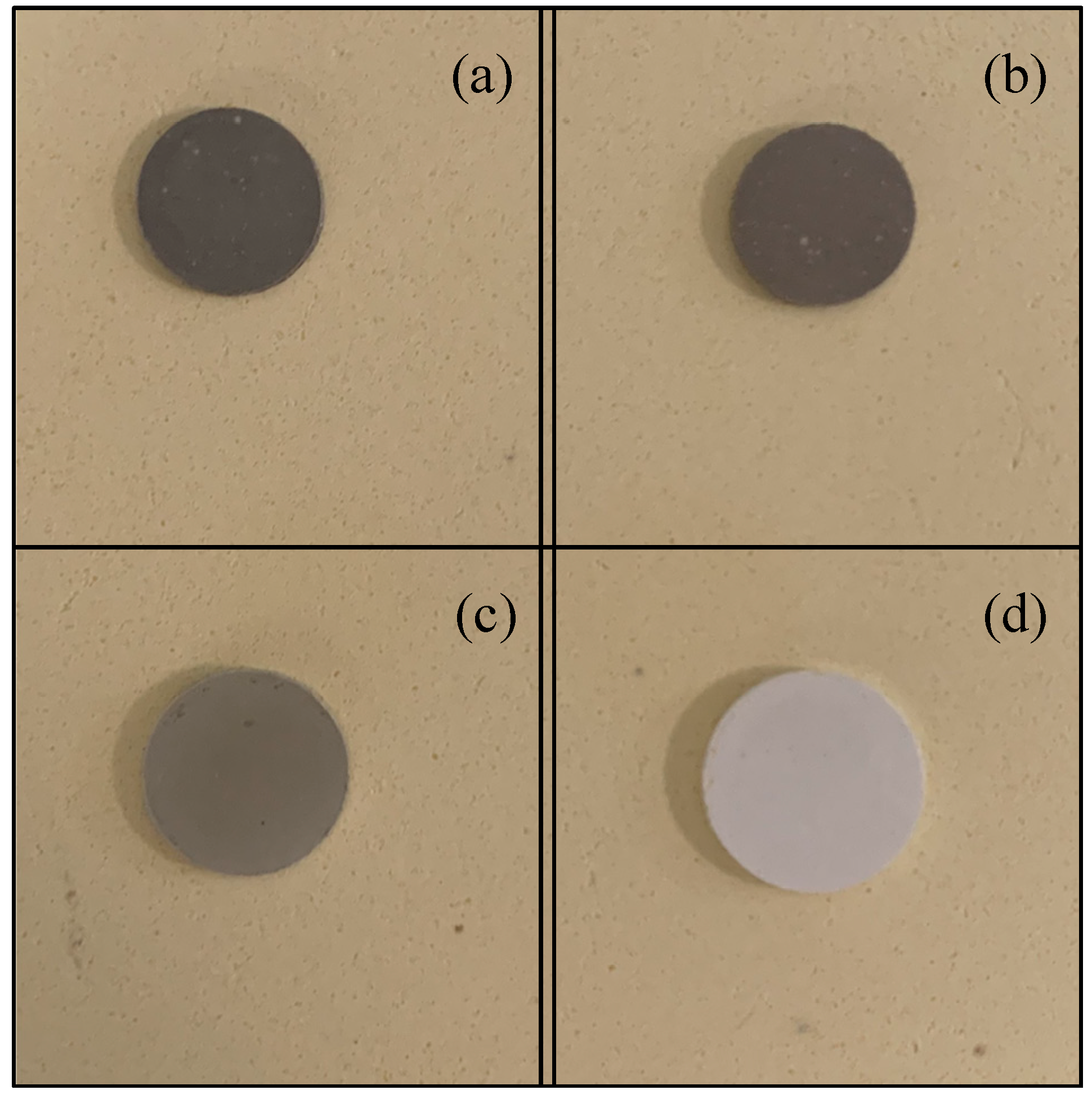
The electrolyte samples are sintered for the 16 designed groups. Range analysis is performed to identify the significance of each factor with respect to the low-temperature densification of GDC electrolytes. The shrinking rate of the sintered samples is measured. Figure 2 shows photos of four samples. The diameters of the GDC particles are all 150 nm for these four pellets. The contents of the sintering aid are 0.076 g, 0.02 g, 0.01 g, and 0 g, respectively. A micrometer is used to measure the size of the sintered sample. Each sample is measured three times, and the average value is obtained. The measured shrinking rates for these four samples are 46.94%, 46.99%, 12.30%, and 9.52%, exhibiting a decreasing trend as the content of the sintering aid declines.

4.1. Statistical Analysis

The range value (Rj) indicates the significance of the j-th factor. A higher Rj value indicates a greater influence on the shrinking rate (y). The results are listed in Table 4. Based on these results, the sequence of significance for the factors are obtained and shown as Figure 3. The significance sequence is the sintering aid content (30.678%) > particle diameter (13.324%) > uniaxial pressure (6.498%) > sintering temperature (6.466%) > binder content (4.127%). The sintering aid content is the most important, at 30.678%. The contribution of the particle diameter of the GDC powder is the second largest. The size of the GDC powder affects the packing structure of the slurry. A smaller grain size helps to improve the packing density. However, if the particle size is too small, the aggregation effect of the nanoparticles cannot be ignored. The effects of the uniaxial pressure and the binder content are relatively small. Imposing on uniaxial pressure is necessary to ensure a high initial packing density of the pellets. The binder also helps to maintain the form of the pellets during the fabrication process, but its content should be kept at a minimum level.
Figure 4 shows shrinking rate according to the orthogonal method. Figure 4a shows that the shrinking rate is the highest when the particle size is 150 nm. As the particle size increases, the shrinking rate generally decreases due to a low packing density. Figure 4b shows the impact of the uniaxial pressure of the infrared tablet press. As the uniaxial pressure increases, the shrinking rate declines due to an improvement of the initial packing density. In practice, an isostatic press with pressure of more than 300 MPa can be used to provide an even higher initial packing density. Figure 4c shows the effect of the binder content. As the binder mass increases, the initial packing density of the pellets decreases because the porosity of the slurry in the subsequent degumming process is increased, leading to a higher shrinking rate during the subsequent sintering process. Therefore, maintaining a low level of binder content aids in the densification of the powder. Figure 4d shows the effect of different masses of sintering aid. It is evident that the addition of CuO sintering aid can enhance the shrinking rate. When the sintering aid content is less than 0.02 g, increasing the mass fraction of the sintering aid can increase the shrinking rate rapidly. However, when the mass of the sintering aid increases further, its effect on the shrinking rate is reduced, also increasing the risk of high electric conductivity. Therefore, the mass of the sintering aid should be set to a suitable range. The effect of the maximum sintering temperature is shown in Figure 4e. When the maximum sintering temperature is less than 1000 °C, a shrinking rate of less than 16% is obtained, resulting in low sintering kinetics. When the maximum sintering temperature is increased beyond 1000 °C, the shrinking rate increases significantly, reaching a maximum of 1050 °C. The results indicate that the shrinking rate is sensitive when the temperature is between 1000–1050 °C. Constrained by the rigid requirement of the metal substrate, the maximum sintering temperature cannot be increased further. In practice, the maximum sintering temperature should be maintained around 1050 °C to obtain a high level of densification.
Subsequently, the uncertainties of the shrinking rates are estimated based on the Kline–McClintock method. It is assumed that X is the function of n independent variables (x1, x2, x3, …, xn) denoted by:
X = f (x1, x2, x3, …, xn).
The uncertainties for the n independent variables are Δx1, Δx2, Δx3, …, and Δxn. The relative uncertainty of X is expressed by:
Δ X X = ( 1 X X x 1 Δ x 1 ) 2 + ( 1 X X x 2 Δ x 2 ) 2 + ( 1 X X x 3 Δ x 3 ) 2 + + ( 1 X X x n Δ x n ) 2 .
The shrinking rate is the function of the measured values of the diameter and thickness of the pellet before and after sintering. Assuming the uncertainty of the measured diameter is 0.2 mm and the thickness is 0.1 mm, the uncertainties of the 16 groups of the shrinking rate are determined according to Equation (12). The results are shown in Figure 5. The uncertainties of the shrinking rate are very low for most of the groups. The average uncertainty of the shrinking rate is 0.0925%. The maximum uncertainty is 0.1169% for test No. 9, with a shrinking rate of 0.3730%. The uncertainties of test Nos. 4, 6, 10, and 15 are also relatively high. The minimum uncertainty is 0.0545% for test No.2. The uncertainties of test Nos. 1, 12, and 14 are also low. Generally, the measured shrinking rates have a high precision, with acceptable uncertainties.

4.2. Characterization

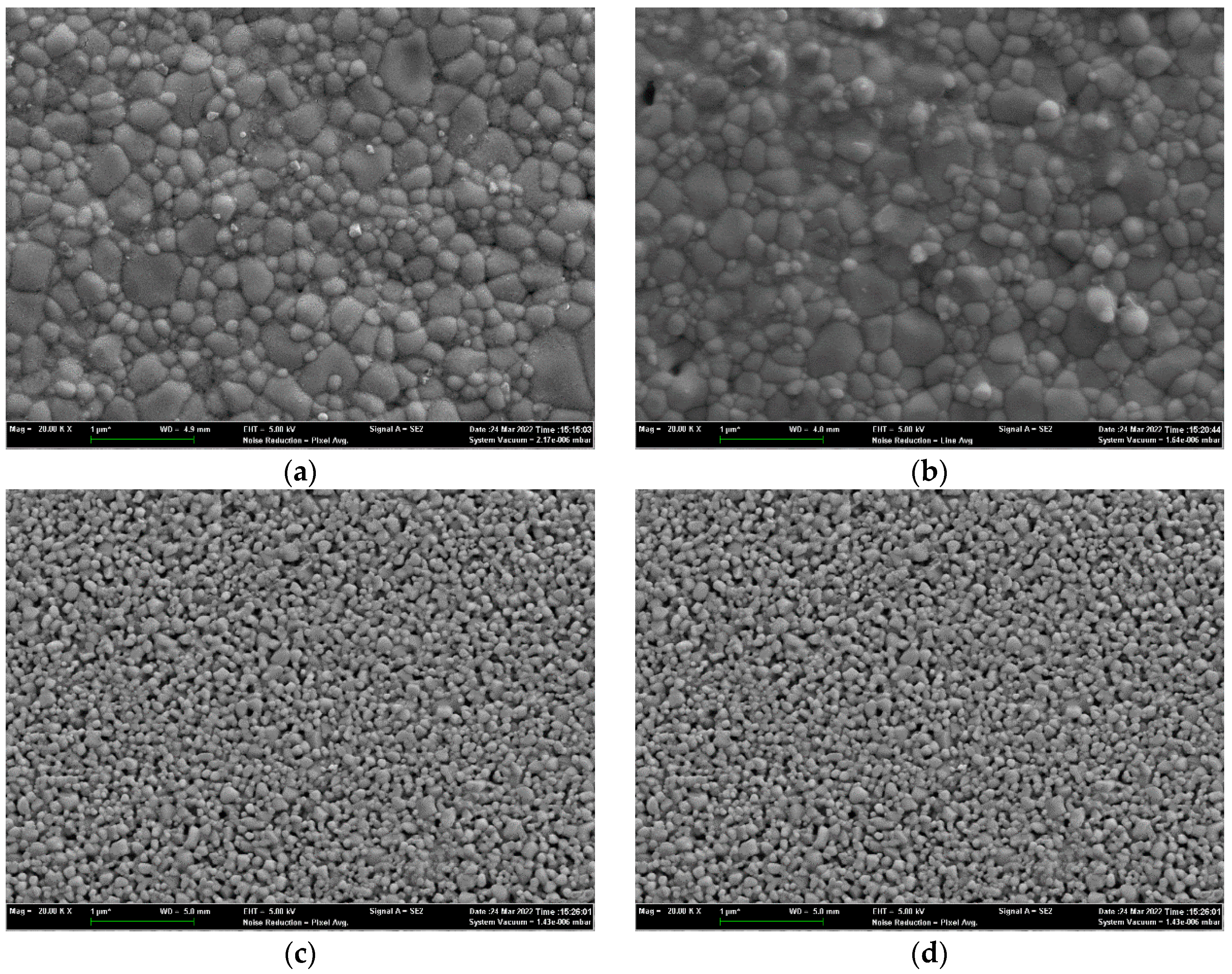
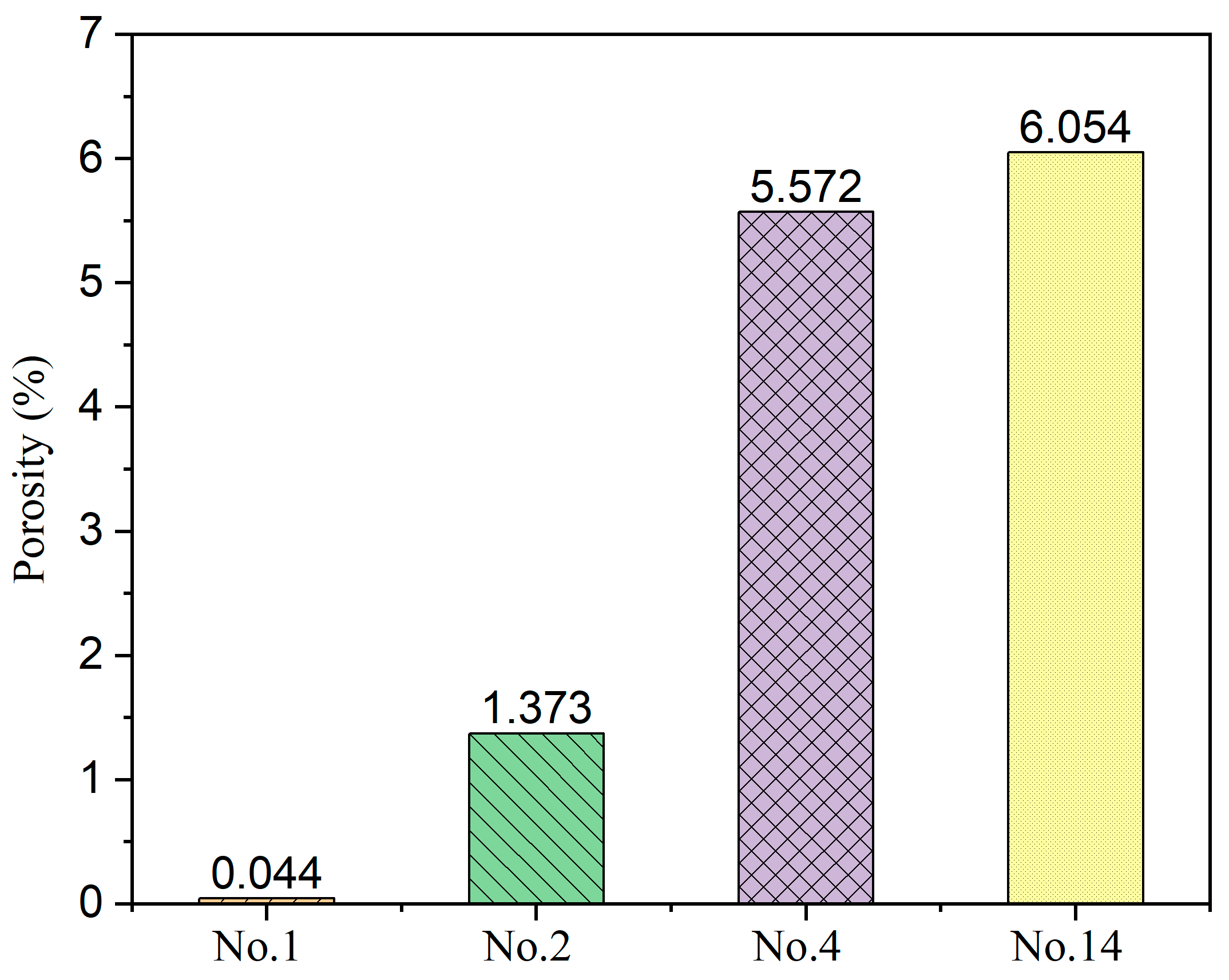
To validate the densification of the sintered pellets, the surface microstructures are measured by SEM. The SEM images Nos. 1, 2, 4, and 14 are shown in Figure 6 with a magnification of 50 K. Good densification is achieved for the No. 1 sample. The boundaries of the grains are visible, and most of the grains have a diameter of less than 1 um. If the grain size is too small, the resistance of ionic conductivity increases along the grain boundaries. However, an annealing treatment can be adopted to obtain a larger grain size. For the No. 2 sample, several small holes can be observed on the surface, although it also highly densified. In contrast, the densification of the 14 other samples is poor. The surfaces of Nos. 4 and 14 samples are porous. Many small particles are aggerated, and sintering necks connect adjacent particles. However, such a high porosity makes it difficult to fulfill the requirement of densification of more than 95%. Figure 7 shows the porosity calculated by ImageJ software, indicating a high consistency with that obtained by range analysis. The samples with a higher content of sintering aid are prone to densification. The mass fractions of the sintering aid for the Nos. 1 and 2 samples are 8.29% and 2.14%, respectively. Generally, a mass fraction of more than 3% increases the risk of high electric conductivity. Therefore, the mass fraction of the sintering aid should be controlled at a suitable level.
Figure 8 shows SEM images of the cross sections of Nos. 1 and 11 with a magnification of 100 K. It is evident that there is no direct connection path between the two sides of sample No. 1, although many small voids exist. Therefore, gas tightness is guaranteed. In comparison, sample No. 11 exhibits high porosity. A gas seal between the anode and the cathode cannot be realized, and the cross-talk phenomenon will be serious.
The conductivity of the sintered GDC electrolyte is measured in air using an electrochemical workstation. GDC exhibits a mixed ionic–electric conducting characteristic [50]. Therefore, the measured conductivity is the summation of the oxygen ions and electrons, as well as holes. The overall conductivity of the No. 1 and 2 samples are tested. EIS data are plotted in Figure 9. The variation trends of the AC impedance curves are similar between the two samples at different temperatures. In each EIS profile, the left side is associated with the ohmic resistance of the electrolyte, whereas the right side indicates the electrolyte–electrode interface resistance [45]. The left intersection point of the impedance curve with the X-axis is the ohmic resistance of the electrolyte, and these values are determined for each profile. The ohmic resistances of the two samples increase as the temperature decreases. The resistance of sample No. 2 is slightly higher than that of No. 1. When the temperature is 650 °C, the resistance of sample No. 1 is 11.23 Ω, whereas that of sample No. 2 is 11.80 Ω. Figure 10 shows the overall conductivity profiles of sample Nos. 1 and 2. The measured overall conductivity of GDC is also plotted in [51]. The measured conductivity is greater than that reported in [51], and working temperature is especially high. Nevertheless, this comparison is preliminary because many of the parameters are not the same as those in [51]. The conductivity of the GDC electrolyte is affected by the particle size, sintering process, and impurity content [20,52,53]. For instance, the samples were sintered at 1400 °C for 7 h in [51]. However, a maximum temperature of less than 1100 °C is used in this study, and the sintering dwell time is 2 h. These differences may lead to large deviations in grain size. Differences in conductivity may occur as a result of the effects of impurities on the grain boundary conductivity [54]. The conductivity trend of sample No. 1 is consistent with that of sample No. 2. The conductivity of sample No. 2 is slightly higher than that of sample No. 1 in the high-temperature region. Because the sintering aid has a high electric conductivity under a reductive atmosphere, its mole fraction is normally maintained at less than 3% [55]. The content of sintering aid in sample No. 1 is slightly higher, which may result in high electric conductivity. For sample No. 2, because the electric conductivity of the GDC electrolyte is very low in an atmosphere with high oxygen partial pressure, the measured results indicate the oxygen ionic conductivity.

5. Conclusions

To overcome the low-temperature densification of the GDC electrolyte, an orthogonal experiment was employed to investigate the effects of sintering parameters, including particle diameter, uniaxial pressure, contents of the binder and sinter aid, and the maximum sintering temperature. The results indicate that the effect of sintering aid content is most significance. A suitable mass fraction of sintering aid is approximately 2.14%. The effect of particle diameter is also large. The density of the GDC electrolyte is more than 95%, with an average particle diameter of 150 nm. The shrinking rate of the samples increases rapidly when the maximum sintering temperature is 1000–1050 °C. The effects of uniaxial pressure and binder content are relatively small in the specified ranges. Microstructural images and EIS data indicate good densification and conductivity of sample No. 2.

Author Contributions

Conceptualization, L.A. and E.W.; methodology, M.Z.; software, M.Z. and E.W.; validation, L.A., H.W. and H.H.; formal analysis, M.Z.; investigation, M.Z.; resources, M.O.; data curation, E.W.; writing—original draft preparation, M.Z.; writing—review and editing, E.W. and L.A.; visualization, M.Z.; supervision, M.O.; project administration, H.W. and H.H.; funding acquisition, E.W., H.W. and H.H. All authors have read and agreed to the published version of the manuscript.

Funding

This research was funded by the National Key Research and Development Program of China, grant number 2021YFB2500400.

Data Availability Statement

Not applicable.

Conflicts of Interest

The authors declare no conflict of interest. The funders had no role in the design of the study; in the collection, analyses, or interpretation of data; in the writing of the manuscript; or in the decision to publish the results.

References

  1. Vostakola, M.F.; Horri, B.A. Progress in Material Development for Low-Temperature Solid Oxide Fuel Cells: A Review. Energies 2021, 14, 1280. [Google Scholar] [CrossRef]
  2. Santhanam, S.; Ullmer, D.; Wuillemin, Z.; Varkaraki, E.; Beetschen, C.; Antonetti, Y.; Ansar, A. Experimental Analysis of a 25 kWe Solid Oxide Fuel Cell Module for Co-Generation of Hydrogen and Power. ECS Trans. 2019, 91, 159–166. [Google Scholar] [CrossRef]
  3. Wu, Z.; Zhu, P.; Yao, J.; Tan, P.; Xu, H.; Chen, B.; Ni, M. Dynamic modeling and operation strategy of natural gas fueled SOFC Engine hybrid power systemwith hydrogen addition by metal hydride for vehicle applications. eTransportation 2020, 5, 100074. [Google Scholar] [CrossRef]
  4. Ballard, A.; Domanski, T.; Rees, L.; Nobbs, C.; Lawrence, N.; Heffer, K.; Harman, J.; Evans, C.; Barnard, P.; Mukerjee, S.; et al. Development of the 5kWe SteelCell® Technology Platform for Stationary Power and Transport Applications. ECS Trans. 2019, 91, 117–122. [Google Scholar] [CrossRef]
  5. Noponen, M.; Torri, P.; Göös, J.; Puranen, J.; Kaar, H.; Pylypko, S.; Õunpuu, E. Elcogen—Next Generation Solid Oxide Cell and Stack Technology. ECS Trans. 2019, 91, 91–97. [Google Scholar] [CrossRef]
  6. Mai, A.; Grolig, J.G.; Dold, M.; Vandercruysse, F.; Denzler, R.; Schindler, B.; Schuler, A. Progress in HEXIS’ SOFC Development. ECS Trans. 2019, 91, 63–70. [Google Scholar] [CrossRef]
  7. Vora, S.D.; Jesionowski, G.; Williams, M.C. Overview of U.S. Department of Energy Office of Fossil Energy’s Solid Oxide Fuel Cell Program for FY2019. ECS Trans. 2019, 91, 27–39. [Google Scholar] [CrossRef]
  8. Hara, D. Toward a Hydrogen Society—Introduction of Representative Projects in Japan. ECS Trans. 2019, 91, 3–7. [Google Scholar] [CrossRef]
  9. Nakao, T.; Inoue, S.; Uenoyama, S.; Takuwa, Y.; Suzuki, M. Progress of SOFC Residential CHP System: Over 50,000 Units Market Experience of Osaka Gas. ECS Trans. 2019, 91, 43–49. [Google Scholar] [CrossRef]
  10. Al-Hamed, K.H.M.; Dincer, I. A new direct ammonia solid oxide fuel cell and gas turbine based integrated system for electric rail transportation. eTransportation 2019, 2, 100027. [Google Scholar] [CrossRef]
  11. Sumi, H.; Nakabayashi, S.; Kawada, T.; Uchiyama, Y.; Uchiyama, N.; Ichihara, K. Demonstration of SOFC Power Sources for Drones (UAVs; Unmanned Aerial Vehicles). ECS Trans. 2019, 91, 149–157. [Google Scholar] [CrossRef]
  12. Brandon, N.P.; Ruiz-Trejo, E.; Boldrin, P. Solid Oxide Fuel Cell Lifetime and Reliability; Elsevier: London, UK, 2017. [Google Scholar]
  13. Bianchi, F.R.; Bosio, B.; Baldinelli, A.; Barelli, L. Optimization of a Reference Kinetic Model for Solid Oxide Fuel Cells. Catalysts 2020, 10, 104. [Google Scholar] [CrossRef] [Green Version]
  14. Mozdzierz, M.; Berent, K.; Kimijima, S.; Szmyd, J.S.; Brus, G. A Multiscale Approach to the Numerical Simulation of the Solid Oxide Fuel Cell. Catalysts 2019, 9, 253. [Google Scholar] [CrossRef] [Green Version]
  15. Ivers-Tiffée, E.; Weber, A.; Herbstritt, D. Materials and technologies for SOFC-components. J. Eur. Ceram. Soc. 2001, 21, 1805–1811. [Google Scholar] [CrossRef]
  16. Mishima, Y. Solid oxide fuel cell with composite electrolyte consisting of samaria doped ceria and Yttria-stabilized zirconia. J. Electrochem. Soc. 1998, 145, 1004. [Google Scholar] [CrossRef]
  17. Horri, B.A.; Selomulya, C.; Wang, H. Electrochemical characteristics and performance of anode-supported SOFCs fabricated using carbon microspheres as a pore-former. Int. J. Hydrogen Energy 2012, 37, 19045–19054. [Google Scholar] [CrossRef]
  18. Kosacki, I.; Rouleau, C.M.; Becher, P.F.; Bentley, J.; Lowndes, D.H. Nanoscale effects on the ionic conductivity in highly textured YSZ thin films. Solid State Ion. 2005, 176, 1319–1326. [Google Scholar] [CrossRef]
  19. Tarancón, A. Strategies for Lowering Solid Oxide Fuel Cells Operating Temperature. Energies 2009, 2, 1130–1150. [Google Scholar] [CrossRef]
  20. Kleinlogel, C.; Gauckler, L.J. Sintering and properties of nanosized ceria solid solutions. Solid State Ion. 2000, 135, 567–573. [Google Scholar] [CrossRef]
  21. Piñol, S.; Morales, M.; Espiell, F. Low temperature anode-supported solid oxide fuel cells based on gadolinium doped ceria electrolytes. J. Power Source 2007, 169, 2–8. [Google Scholar] [CrossRef]
  22. Bianchi, F.R.; Spotorno, R.; Piccardo, P.; Bosio, B. Solid Oxide Fuel Cell Performance Analysis through Local Modelling. Catalysts 2020, 10, 519. [Google Scholar] [CrossRef]
  23. Tucker, M.C. Progress in metal-supported solid oxide fuel cells: A review. J. Power Source 2010, 195, 4570–4582. [Google Scholar] [CrossRef]
  24. Na, A.; Lue, Z.; Chen, K.; Huang, X.; Du, X.; Su, W. Effects of anode surface modification on the performance of low temperature SOFCs. J. Power Source 2007, 171, 489–494. [Google Scholar]
  25. Kim, S.-D.; Lee, J.-J.; Moon, H.; Hyun, S.-H.; Moon, J.; Kim, J.; Lee, H.-W. Effects of anode and electrolyte microstructures on performance of solid oxide fuel cells. J. Power Source 2007, 169, 265–270. [Google Scholar] [CrossRef]
  26. Singhal, S. Solid oxide fuel cells for stationary, mobile, and military applications. Solid State Ion. 2002, 152, 405–410. [Google Scholar] [CrossRef]
  27. Anwar, M.; Kumar, S.; Arshi, N.; Ahmed, F.; Seo, Y.; Lee, C.; Koo, B.H. Structural and optical study of samarium doped cerium oxide thin films prepared by electron beam evaporation. J. Alloys Compd. 2011, 509, 4525–4529. [Google Scholar] [CrossRef]
  28. Stambouli, A.; Traversa, E. Solid oxide fuel cells (SOFCs): A review of an environmentally clean and efficient source of energy. Renew. Sustain. Energy Rev. 2002, 6, 433–455. [Google Scholar] [CrossRef]
  29. Kulkarni, S.; Duttagupta, S.; Phatak, G. Taguchi design of experiments for optimization of ionic conductivity in nanocrystalline Gadolinium doped Ceria. Ceram. Int. 2015, 41, 8973–8980. [Google Scholar] [CrossRef]
  30. Burke, J.E. Role of Grain Boundaries in Sintering; Springer: Dordrecht, The Netherlands, 1990. [Google Scholar]
  31. Murutoglu, M.; Ucun, T.; Ulasan, O.; Buyukaksoy, A.; Tur, Y.K.; Yilmaz, H. Cold sintering-assisted densification of GDC electrolytes for SOFC applications. Int. J. Hydrogen Energy 2022, 47, 19772–19779. [Google Scholar] [CrossRef]
  32. Lv, Z.; Yao, P.; Guo, R.; Dai, F. Study on zirconia solid electrolytes doped by complex additives. Mater. Sci. Eng. A 2007, 458, 355–360. [Google Scholar] [CrossRef]
  33. Bjørk, R.; Tikare, V.; Frandsen, H.L.; Pryds, N. The Effect of Particle Size Distributions on the Microstructural Evolution During Sintering. J. Am. Ceram. Soc. 2012, 96, 103–110. [Google Scholar] [CrossRef] [Green Version]
  34. Chaim, R.; Chevallier, G.; Weibel, A.; Estournès, C. Grain growth during spark plasma and flash sintering of ceramic nanoparticles: A review. J. Mater. Sci. 2017, 53, 3087–3105. [Google Scholar] [CrossRef] [Green Version]
  35. Miyake, K.; Hirata, Y.; Shimonosono, T.; Sameshima, S. The Effect of Particle Shape on Sintering Behavior and Compressive Strength of Porous Alumina. Materials 2018, 11, 1137. [Google Scholar] [CrossRef] [PubMed] [Green Version]
  36. Rehman, S.U.; Shaur, A.; Kim, H.; Joh, D.W.; Song, R.; Lim, T.; Hong, J.; Park, S.; Lee, S. Effect of transition metal doping on the sintering and electrochemical properties of GDC buffer layer in SOFCs. Int. J. Appl. Ceram. Technol. 2020, 18, 511–524. [Google Scholar] [CrossRef]
  37. Accardo, G.; Bae, J.K.; Yoon, S.P. Evaluation of the Microstructure and the Electrochemical Properties of Ce0.8(1−x)Gd0.2(1−x)CuxO [1.9(1−x)+x] Electrolytes for IT-SOFCs. Appl. Sci. 2020, 10, 4573. [Google Scholar] [CrossRef]
  38. Grilo, J.P.D.F.; Macedo, D.A.; Nascimento, R.M.D.; Marques, F.M. Performance of GDC with alkali metal carbonates as sintering aids. Solid State Ion. 2020, 346, 115221. [Google Scholar] [CrossRef]
  39. Acccardo, G.; Frattini, D.; Ham, H.C.; Yoon, S.P. Direct addition of lithium and cobalt precursors to Ce0.8Gd0.2O1.95 electrolytes to improve microstructural and electrochemical properties in ITSOFC at lower sintering temperature. Ceram. Int. 2019, 45, 9348–9358. [Google Scholar] [CrossRef]
  40. Accardo, G.; Audasso, E.; Yoon, S.P. Unravelling the synergistic effect on ionic transport and sintering temperature of nanocrystalline CeO2 tri-doped with Li Bi and Gd as dense electrolyte for solid oxide fuel cells. J. Alloys Compd. 2022, 898, 162880. [Google Scholar] [CrossRef]
  41. Ishii, A.; Ishijima, H.; Kobayashi, K.; Oikawa, I.; Takamura, H. Insight into low-temperature sintering of samarium-doped ceria mixed with scavenging lithium. Acta Mater. 2021, 224, 117529. [Google Scholar] [CrossRef]
  42. Taguchi, G.; Cariapa, V. Taguchi on Robust Technology Development. J. Press. Vessel Technol. 1993, 115, 336–337. [Google Scholar] [CrossRef]
  43. Mori, T.; Tsai, S.C. Taguchi Methods: Benefits, Impacts, Mathematics, Statistics, and Applications; ASME Press: New York, NY, USA, 2011. [Google Scholar]
  44. Korkmaz, A.A. Optimization of Smokeless Fuel Production from Lignite by Taguchi Orthogonal Design. Solid Fuel Chem. 2021, 55, 444–449. [Google Scholar] [CrossRef]
  45. Ghaemi, N.; Slade, R.C.; Horri, B.A. A benzoate coprecipitation route for synthesizing nanocrystalline GDC powder with lowered sintering temperature. Ceram. Int. 2021, 47, 20009–20018. [Google Scholar] [CrossRef]
  46. Lyu, Q.; Zhu, T.; Qu, H.; Sun, Z.; Sun, K.; Zhong, Q.; Han, M. Lower down both ohmic and cathode polarization resistances of solid oxide fuel cell via hydrothermal modified gadolinia doped ceria barrier layer. J. Eur. Ceram. Soc. 2021, 41, 5931–5938. [Google Scholar] [CrossRef]
  47. Costilla-Aguilar, S.; Pech-Canul, M.; Escudero, M.; Cienfuegos-Pelaes, R.; Aguilar-Martínez, J. Gadolinium doped ceria nanostructured oxide for intermediate temperature solid oxide fuel cells. J. Alloys Compd. 2021, 878, 160444. [Google Scholar] [CrossRef]
  48. Mishra, T.P.; Lenser, C.; Raj, R.; Guillon, O.; Bram, M. Development of a processing map for safe flash sintering of gadolinium-doped ceria. J. Am. Ceram. Soc. 2021, 104, 4316–4328. [Google Scholar] [CrossRef]
  49. Zhao, P.; Ge, S.; Yoshikawa, K. An orthogonal experimental study on solid fuel production from sewage sludge by employing steam explosion. Appl. Energy 2013, 112, 1213–1221. [Google Scholar] [CrossRef]
  50. Zhou, X.; Zhou, F. Application of La0.3Sr0.7Fe0.7Ti0.3O3-δ/GDC electrolyte in LT-SOFC. Int. J. Hydrogen Energy 2021, 46, 9988–9995. [Google Scholar] [CrossRef]
  51. Wang, S.; Kobayashi, T.; Dokiya, M.; Hashimoto, T. Electrical and Ionic Conductivity of Gd-Doped Ceria. J. Electrochem. Soc. 2000, 147, 3606–3609. [Google Scholar] [CrossRef]
  52. Liu, Q.; Chan, S.; Fu, C.; Pasciak, G. Fabrication and characterization of large-size electrolyte/anode bilayer structures for low-temperature solid oxide fuel cell stack based on gadolinia-doped ceria electrolyte. Electrochem. Commun. 2009, 11, 871–874. [Google Scholar] [CrossRef]
  53. Gil, V.; Tartaj, J.; Moure, C.; Duran, P. Rapid Densification by Using Bi2O3 as an Aid for Sintering of Gadolinia-doped Ceria Ceramics. Ceram. Int. 2007, 33, 471–475. [Google Scholar] [CrossRef]
  54. Song, X.; Liao, D.; Lian, Z.; Chen, F.; Peng, K. Effects of monovalent alkali metals on grain boundary conductivity and electrochemical properties of gadolinia-doped ceria electrolyte. Ceram. Int. 2021, 47, 18773–18782. [Google Scholar] [CrossRef]
  55. Christoph, K. Process for the Production of Doped Cerium Oxide Ceramics. EP1000913, 13 November 1998. [Google Scholar]
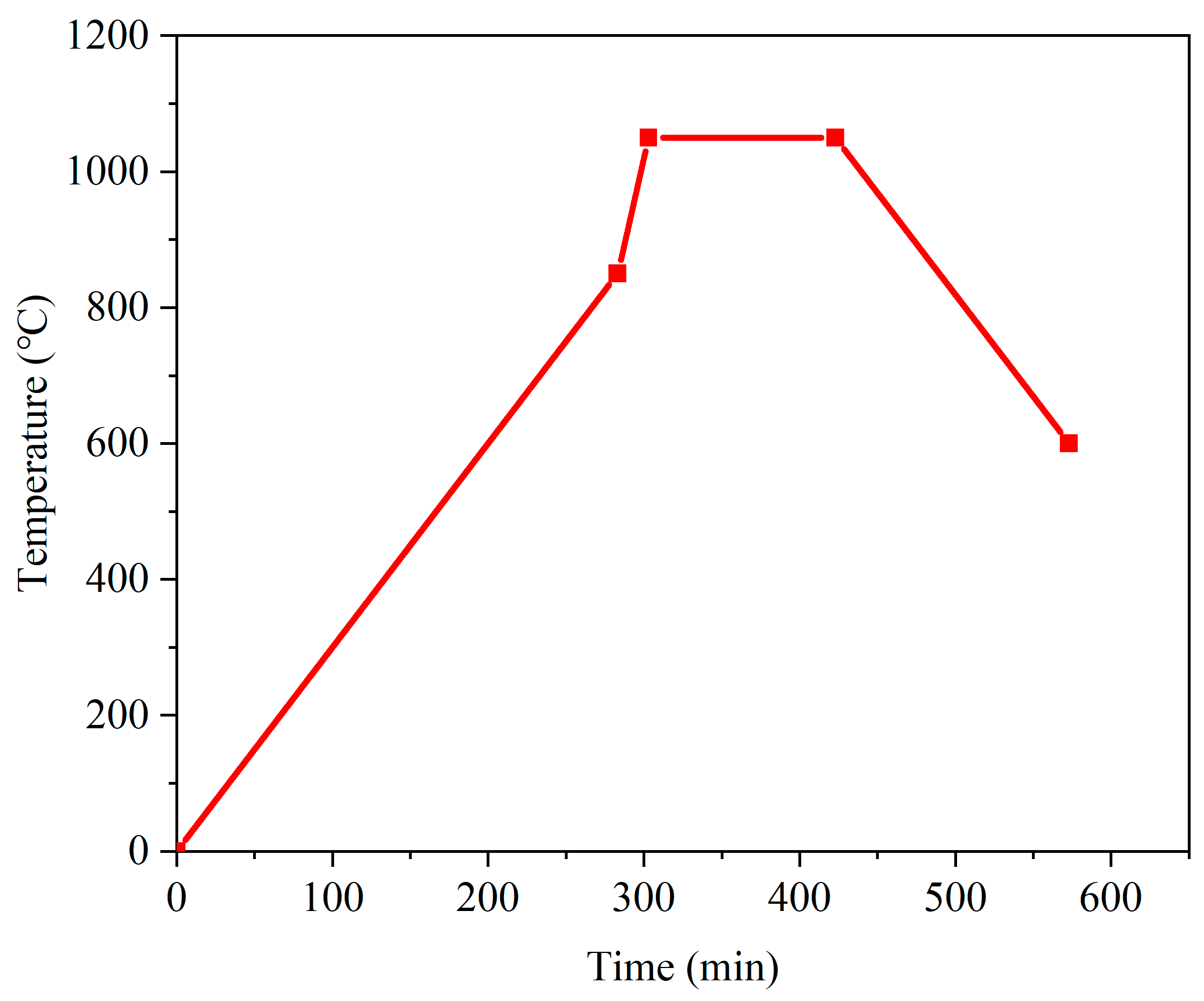
Figure 1. Sintering temperature profile with a maximum temperature of 1050 °C.
Catalysts 12 00831 g001
Figure 2. Photos of four sintered electrolytes with different contents of sintering aid: (a) No. 1, 0.076 g; (b) No. 2, 0.020 g; (c) No. 3, 0.010 g; (d) No. 4, 0 g.
Catalysts 12 00831 g002
Figure 3. Significance sequence of the sintering parameters based on range analysis.
Catalysts 12 00831 g003
Figure 4. Effects of sintering parameters on the shrinking rate of GDC electrolyte: (a) particle diameter; (b) uniaxial pressure; (c) binder mass; (d) sintering aid mass; (e) maximum sintering temperature.
Catalysts 12 00831 g004
Figure 5. Results of the uncertainty analysis for the shrinking rate.
Catalysts 12 00831 g005
Figure 6. SEM images of the sample surface: (a) No. 1; (b) No. 2; (c) No. 4; (d) No. 14.
Catalysts 12 00831 g006
Figure 7. Porosity calculated based on SEM surface images.
Catalysts 12 00831 g007
Figure 8. Cross-sectional SEM images: (a) No. 1; (b) No. 11.
Catalysts 12 00831 g008
Figure 9. EIS plots of the GDC pellets measured at different temperatures: (a) No. 1; (b) No. 2.
Catalysts 12 00831 g009
Figure 10. Overall conductivity measured in air.
Catalysts 12 00831 g010
Table 1. Lists of the main equipment.
EquipmentManufacturerType
Three-roll grinderZYEZYTR-50
HomogenizerZYEZYMC-200V
Vacuum dryerAISETYLE-2000
Manual infrared tablet press Tianjin Optical Instruments FW-4 24T
High-temperature sintering furnaceHefei KejingKSL-1700X
Tube sintering furnaceHefei KejingOTF-1200X
Electrochemical analyzerMetrohmAUT302N
Table 2. Specified levels of each factor.
SymbolFactors Level 1Level 2Level 3Level 4
GParticle size (nm)150 300500700
PUniaxial pressure (MPa)20 103015
ABinder mass (g)0.560.80.30.1
SSintering aid mass (g)0.0760.020.010
TSintering temperature (°C)950105010101000
Table 3. Designed orthogonal array (L16 (45)) for the experiment.
Case No.Factors
GPAST
111111
212222
313333
414444
521234
622143
723412
824321
931342
1032431
1133124
1234213
1341423
1442314
1543241
1644132
Table 4. Results of range analysis.
ValueGPAST
K j 1 115.849 87.957 86.138 139.576 63.349
K j 2 62.552 95.662 98.733 116.215 107.302
K j 3 67.900 61.965 66.425 48.271 89.214
K j 4 74.625 75.341 69.629 16.863 61.060
K ¯ j 1 28.962 21.989 21.535 34.894 15.837
K ¯ j 2 15.638 23.915 24.683 29.054 26.826
K ¯ j 3 16.975 15.491 16.606 12.068 22.303
K ¯ j 4 18.656 18.835 17.407 4.216 15.265
R j 13.324 6.498 4.127 30.678 6.466
Publisher’s Note: MDPI stays neutral with regard to jurisdictional claims in published maps and institutional affiliations.