Article

Photocatalytic Degradation of Magenta Effluent Using Magnetite Doped TiO2 in Solar Parabolic Trough Concentrator

by
Gordana Pucar Milidrag
1,
Jasmina Nikić
1,*,
Vesna Gvoić
2,
Aleksandra Kulić Mandić
1,
Jasmina Agbaba
1,
Milena Bečelić-Tomin
1 and
Djurdja Kerkez
1
1
Department of Chemistry, Biochemistry and Environmental Protection, Faculty of Sciences, University of Novi Sad, Trg Dositeja Obradovica 3, 21000 Novi Sad, Serbia
2
Department of Graphic Engineering and Design, Faculty of Technical Sciences, University of Novi Sad, Trg Dositeja Obradovica 6, 21000 Novi Sad, Serbia
*
Author to whom correspondence should be addressed.
Catalysts 2022, 12(9), 986; https://doi.org/10.3390/catal12090986
Submission received: 14 July 2022 / Revised: 17 August 2022 / Accepted: 18 August 2022 / Published: 1 September 2022

Abstract

:
Due to population growth and industrial development consumption of non-renewable energy sources, and consequently pollution, has increased. In order to reduce energy utilisation and preserve the environment, developed and developing countries are increasingly trying to find solutions based on renewable energy sources. Cost-effective wastewater treatment methods using solar energy would significantly ensure effective water source utilisation, thereby contributing towards sustainable development goals. In this paper, special emphasis is given to the use of solar energy as the driving force of the process, as well as the use of highly active magnetic TiO2-based catalysts. Therefore, in this study, we investigated the possibility of photocatalytic degradation of aqueous magenta graphic dye using titanium dioxide as a catalyst and DSD model in order to achieve the best process optimisation. TiO2 was successfully coated with magnetic nanoparticles by one step process and characterized using different techniques (BET, SEM/EDS, FTIR, XRD). Based on DSD statistical method optimal reaction conditions were pH = 6.5; dye concentration 100 mg/L; TiO2–Fe3O4 0.6 g/L, at which the highest degree of magenta dye decolourisation was achieved (85%). Application of solar energy coupled with magnetic TiO2 catalyst which could be recovered and reused makes this approach a promising alternative in green wastewater treatment.

Graphical Abstract

1. Introduction

Due to the growth of the world population accompanied by rapid industrial and technological progress, there is an increasing need for water consumption, which leads to the appearance of a lack of clean water as well as adequate sustainable treatments.
The graphic industry is an important source of environmental pollution. Due to the lack of adequate treatment of contaminated effluent, it is most often discharged directly into the recipient. Therefore, synthetic dyes can be a potential hazard for living organisms [1]. It is estimated that about 15% of the total paint production was lost and released through effluents during the production itself, as well as during the dyeing process [2,3]. With conventional wastewater treatment, such as secondary biodegradation, many pollutants cannot be completely removed. On the other hand, with advanced technologies, such as reverse osmosis, adsorption on activated carbon, and advanced oxidation processes, it is possible to obtain high water quality. However, they are expensive and economically unprofitable processes [4].
Photocatalytic degradation using titanium dioxide (TiO2) as a catalyst is a promising and widely used method for the treatment of wastewater contaminated with organic and inorganic pollutants [5,6,7,8]. Titanium dioxide has better catalytic properties compared to other semiconductors such as zinc oxide and silicon oxide [4]. The two principal catalytic phases of TiO2, anatase and rutile, have numerous structural and functional differences. Commercially available anatase is typically less than 50 nm in size and these particles have a band gap of 3.2 eV, corresponding to a UV wavelength of 385 nm. Rutile has a smaller band gap of 3.0 eV with excitation wavelengths that extend into the visible at 410 nm. Nevertheless, anatase is generally regarded as the more photochemically active phase of titania, presumably due to the combined effect of lower rates of recombination and higher surface adsorptive capacity [9]. However, the practical applications of TiO2 are greatly limited due to the wide band gap and the resultant low utilisation of solar energy and fast recombination of photogenerated electrons and holes [10]. Therefore, the photocatalytic activity of titania must be further improved. For example, doping TiO2 with transition metals can result in better photocatalytic conversions due to a reduction in the band-gap and the recombination rate of the electron hole pair [11,12,13,14]. On the other hand, nanosized TiO2 is very difficult to separate after treatment and therefore complex and expensive processes are required [4]. In addition, separation of TiO2 might not take place completely which may result in increased toxicity and secondary contamination. To overcome these disadvantages preparation of TiO2 photocatalysts with magnetic properties, can improve the easy separation and recovery of these materials from an aqueous medium by using external magnets [15,16]. Recent studies demonstrated that magnetite (Fe3O4) nanoparticles are the most promising magnetic materials due to their appealing characteristics such as non-toxicity, chemical stability, high magnetic properties, and easy preparation [17]. Moreover, studies suggest that Fe3O4 nanoparticles are effective heterogeneous Fenton catalysts as compared to other iron oxides possibly because they have Fe2+ in their structure to enhance the production rate of hydroxyl radicals [18].
Many different methods of TiO2 modification with magnetic nanoparticles have been studied [19,20,21,22,23]. Gnanasekaran et al. [24] used precipitation and sol-gel mixed procedures to prepare a TiO2@Fe3O4 nanocomposite for the photocatalytic degradation of methylene blue and methyl orange, as well as of colourless phenol and reported that TiO2@Fe3O4 effectively degraded contaminants under visible light irradiation. In another study, the Fe3O4/TiO2 (P25) showed better photocatalytic ability compared to that of Fe3O4/TiO2 (UV100) for methyl orange dye degradation (10 ppm) under UV irradiation (λ = 254 nm) [25]. Some of the methods reported in literature applied for modification of TiO2 with magnetite nanoparticles are cheap and easy, such as chemical co-precipitation, non-thermal method [26,27,28], and sonochemical method [29], while some other modifications are expensive and complex [30].
Application of parabolic through concentrator (PTC) reactor in wastewater treatment is new, while the use of hybrid magnetic nanophotocatalyst (TiO2–Fe3O4) in this system has not been evaluated so far. Namely, PTC reactors consist of a highly reflective surface area, known as a parabola, an absorption tube located in the focus of the parabola, and a Sun tracking system [31,32]. They are mostly applied to generate hot water or to produce renewable electricity. On the other hand, PTCs could be used in solar photochemical processes due to the collection of only high-energy photons of short wavelengths. Here, reaction fluid (wastewater effluent) must be directly exposed to solar radiation. Generally, the most suitable time to use this type of solar reactor is during summertime, whose efficiency could be affected by weather conditions (clouds) and position (North-South; East-West) [32].
Numerous tests have established that the effectiveness of the applied treatment depends on several process parameters, which require the optimisation of the entire process. With the improvement of chemical treatments, researchers also face the problem of a limited number of operating variables, which is caused by the fact that the number of experiments largely increases when more variables are included in the experimental design. To overcome this problem, it is necessary to use statistical screening methods that will identify significant variables and eliminate irrelevant ones. For this purpose, it is possible to use a set of empirical statistical methods that are based on the application of quantitative data from appropriately designed experiments with the aim of determining optimal conditions. A powerful tool for system characterisation under different experimental conditions involves the integration of simple and robust statistical methods within the applied methodology with the aim of obtaining statistically significant conclusions. Accordingly, a new generation of experimental design, definitive screening design (DSD), was introduced by Jones and Nachtsheim [33,34]. The principle of the DSD statistical method is based on the application of a numerical algorithm that maximizes the determinant of the matrix of the main effect model. The analysis conceived in this way is used to determine significant factors and to predict their two-factor interactions, but also to estimate the coefficient of the equation model that describes the total number of performed experiments. Compared to the traditional statistical methodology of response surface followed by Box Behnken or central composite design, this statistical method allows the application of a significantly reduced number of performed experiments with maximum precision [33,35]. In addition, DSD realizes the potential to estimate for more than six factors the full second-order polynomial model, Equation (1), in any combination of three factors, a feature absent in all other conventional screening methods, such as factorial or fractional factorial designs, according to the equation [36]:
𝑦 = 𝑏0 + 𝑏1𝑥1 + 𝑏2𝑥2 + … + 𝑏𝑛𝑥𝑛 + Σ𝑏𝑖𝑘𝑥𝑖𝑥𝑘 + Σ𝑏𝑖𝑖𝑥𝑖2
where y is the dependent variable, b0 is a constant, b1 to bi are the regression coefficients that describe the effect of each calculated term in the final regression models, xi is the independent variable in the form of coded factors, and xixk and xi2 represent interactions and quadratic factors, respectively.
In the first part of our work, we applied a simple ultrasonic-assisted method to modify TiO2 with magnetite nanoparticles to obtain TiO2–Fe3O4 photocatalyst. After complete characterisation of this photocatalyst, its potential was evaluated in a novel application of PTC reactor and renewable solar radiation. The photocatalytic reaction was implemented to efficiently degrade magenta dye commonly used in the graphic industry and present in wastewater effluents. In addition, DSD statistical method for wastewater treatment process optimisation was used to optimize several process parameters (dye concentration, pH value, and catalyst concentration). Enabling the use of photocatalytic processes based on solar radiation coupled with bifunctional catalysts further provides a green and sustainable approach to wastewater treatment.

2. Results

2.1. Catalyst Characterisation

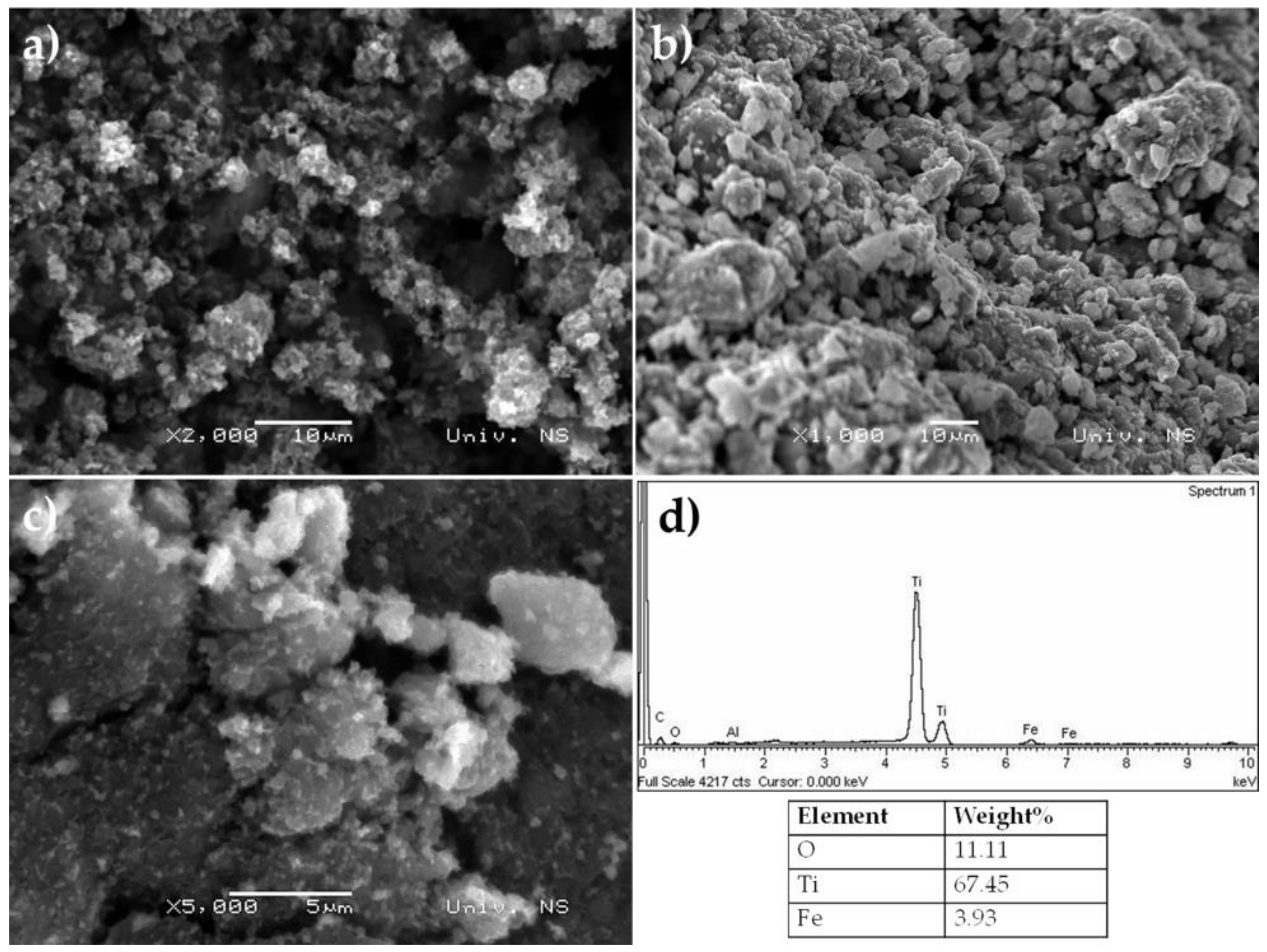
2.1.1. Scanning Electron Microscopy (SEM) and Energy Dispersive X-Ray (EDX)

Morphology of Fe3O4, TiO2, and TiO2–Fe3O4 synthesized materials is shown by SEM images (Figure 1a–c). Figure 1a shows large magnetite aggregates with a smooth surface, while pure titanium shows the morphology of small powder particles (Figure 1b). It can be noticed that particles of TiO2–Fe3O4 have a spherical shape and have a tendency to agglomerate (Figure 1c), demonstrating that the degree of agglomeration and particle size is affected by iron doping. There is also less porosity of these sorbents when compared to pure titanium, which speaks in favour of the good incorporation of magnetite into the porous structure of titanium and may be also responsible for its higher catalytic activity [37]. Vinosel et al. [26] applied a similar method of synthesis of TiO2–Fe3O4 and showed that the morphology of Fe3O4/TiO2 nanocomposite was spherical in shape and uniform sizes of nanoparticles with strong agglomeration, which was consistent with results obtained in our work. Furthermore, other authors who also applied ultrasonic-assisted deposition precipitation method have reported nanospheres morphology for Fe3O4/TiO2 nanocomposite [27,28].
EDX (Figure 1d) was used to determine the elemental content of TiO2–Fe3O4 from which it can be seen that the sample contains Ti, Fe, and O, which indicates the purity of the synthesized sample.

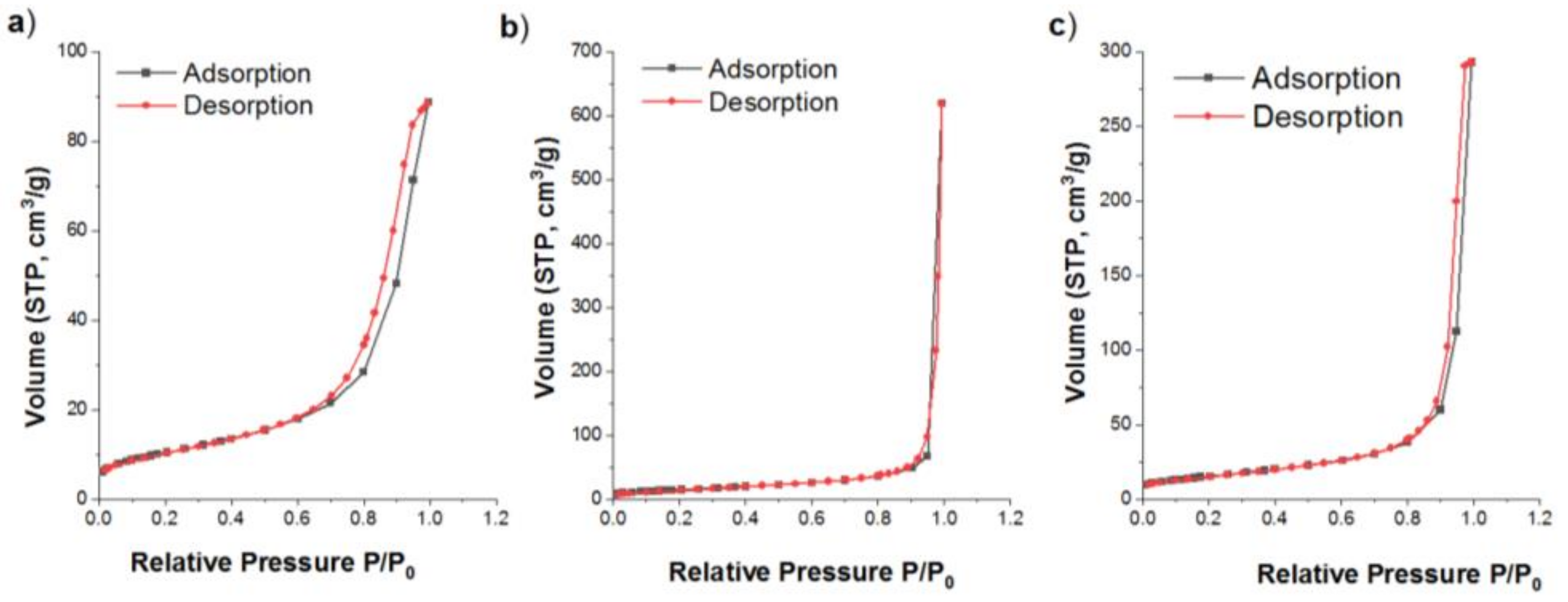
2.1.2. Nitrogen Adsorption–Desorption Isotherms (BET)

Nitrogen adsorption–desorption isotherms of the Fe3O4, TiO2, and TiO2–Fe3O4 are present in Figure 2, while the corresponding calculated textural parameters are given in Table 1. As can be seen from Figure 2a,c, the adsorption–desorption isotherms of the Fe3O4 and TiO2–Fe3O4 are very similar and can be classified as Type IV isotherms with H1 hysteresis loops, according to IUPAC classification of N2 adsorption–desorption isotherms [38]. This means that Fe3O4 and Fe3O4–TiO2 can be categorized as mesoporous materials consisting of agglomerates of approximately uniform spheres or well-defined cylindrical pore channels.
In contrast to Fe3O4 and TiO2–Fe3O4, TiO2 shows adsorption–adsorption isotherms which are characteristics of non-porous and macroporous material (Type II isotherms) and type H3 hysteresis loop (Figure 2b). In the adsorption branch at P/P0 = 0.05 a monomolecular coverage is reached. Further, the adsorption branch presents a small increase up to P/P0 = 0.7. A more gradual curvature is an indication of a significant amount of overlap of monolayer coverage and the onset of multimolecular (multilayer) coating. Here the slope of the curve depends on the mesoporous structure. In mesopores, it is possible to build up a multimolecular coating. At relative pressures near 1, structural information for the external surface area and macropores are included. A significant amount of adsorbed gas in this area indicates a large contribution of macropores and open surfaces. Hysteresis is detectable because of capillary condensation in the pores. The shape of the hysteresis indicates the favourable shape of the pores, while the hysteresis’ end (where the adsorption and the desorption branches are equal) determines the smallest diameter of the open pores. For TiO2 this point is at rather high relative pressures so it can be concluded that only the macropores are open pores while the mesopores are closed. The combination of a type II isotherm and a hysteresis type H3 indicates the presence of plate-like particles with slit-shaped pores [38,39,40]. The isotherm type obtained for TiO2 shows that this is a rather non-porous material, and extensive photocatalytic application of this material, in general, is attributed mainly to the nano-sized particles, relatively high surface area, and optimum pore volume. Pore distribution showed a distinct presence of pores with a diameter size of 35.1 nm for TiO2, corresponding to larger mesopores, while Fe3O4 and TiO2–Fe3O4 may be considered more common mesoporous materials (<20 nm) [41]. Moreover, the results imply that modification of TiO2 with Fe3O4 has led to changes in both, pore size distribution and pore geometry since the pore size of TiO2 decreased almost twice after modification with Fe3O4 nanoparticles (17.1 nm).
The specific surface areas of Fe3O4 were 39.1 m2/g and was comparable with commercial magnetite nanoparticles. Similarly, ref. [42] reported that the specific surface area of TiO2 P25 nanopowders was 50 ± 3 m2/g versus 52.1 m2/g obtained for the TiO2 P25 in our work. After modification of TiO2 with Fe3O4, the BET surface area of TiO2–Fe3O4 was slightly higher, while the mesopore volume of this composite (0.423 cm3g) was more than twice reduced compared to the starting TiO2 (0.921 cm3g). This further confirms the assumption that Fe3O4 nanoparticles occupied the pore of TiO2 during the synthesis of TiO2 P25. Lezner et al. [43] also reported that the BET specific surface area of TiO2 P25 remains almost unchanged after impregnation with iron. Namely, they used a different amount of iron (0.5–10 wt.%) for surface coating of TiO2 P25 and showed that the specific surface of coated materials was slightly higher (53 to 56 m2/g, depending on iron content (0.5–5 wt.%) than that for pure TiO2 P25 (50 m2/g).

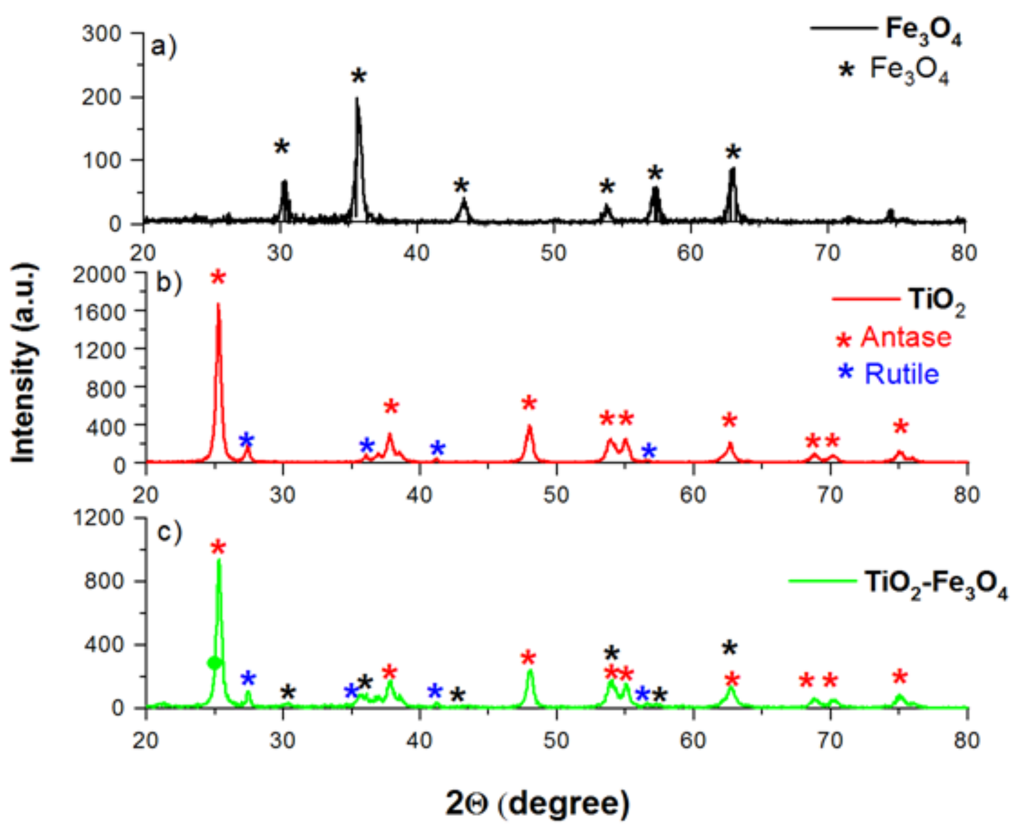
2.1.3. X-Ray Diffraction (XRD)

The XRD pattern of synthesized Fe3O4 nanoparticles (Figure 3a) showed good agreement with the phase structure of magnetite with sharp peaks at 2θ = 30.4°, 35.6°, 37.2°, 43.4°, 47.3°, 53.2°, 57.4°, and 62.5, corresponding to crystal planes of (220), (311), (222), (400), (331), (422), (511), and (440), respectively [4]. These peaks were also found in the XRD pattern of Fe3O4–TiO2, thus suggesting that Fe3O4 attached on the surface of TiO2 maintain their crystal cubic inverse spinel structure and magnetic properties [44]. The peaks observed on the XRD pattern of uncoated TiO2 (Figure 3b) at 2θ = 25.4°, 37.8°, 48.1°, 54.0°, 55.1°,62.7°, 68.8°, 70.2°, and 75.1° match very well with (101), (004), (200), (105), (211), (204), (116), (220), and (215) crystal planes of anatase [45], while the peaks observed at 2θ = 27.4°, 36.1°, 41.2°, and 56.5° are assigned to the (110), (101), (111), and (220) planes of rutile, indicates that P25–TiO2 powder consisted of both phases (83 wt.% of anatase and 17 wt.% of rutile). Peaks characteristics for anatase and rutile were also observed in XRD patterns of TiO2–Fe3O4 (Figure 3c) but their intensity was lower compared with those obtained in the XRD pattern of TiO2 (Figure 3b), which can be ascribed to the shielding effect of magnetic nanoparticles formed on the surface of the TiO2. Other authors also reported that titania coated with magnetic nanoparticles led to decreased peak intensity [46]. However, we suggest that the photocatalytic activity of TiO2 in TiO2–Fe3O4 maintained the same after coating their surface with magnetite nanoparticles since these composites keep both phases of TiO2. Hurum et al. [9] reported that TiO2 composed of mixed-phase of anatase and rutile has better photocatalytic activities compared with the pure phase of TiO2 since the rutile extends the useful range of photoactivity into the visible region and structural arrangement of the similarly sized TiO2 crystallites creates hot spots at the rutile-anatase interface.
The mean crystallite size of the Fe3O4, TiO2, and TiO2–Fe3O4 was calculated using the Scherer equation [47]. The size of anatase crystallite was 23 nm and 37 nm in TiO2 and TiO2–Fe3O4, respectively, while the crystallite size of magnetite nanoparticles was 18 nm. These values were comparable with those obtained in other studies for Fe3O4 [48,49], TiO2 (33 nm) [50] and TiO2–Fe3O4 core/shell nanocubes (30 nm) [46]. Jung et al. [51] reported that photoactivity of TiO2 depends on the crystallite size of anatase and linearly increased with increasing its crystallite size. Since the crystallite size of anatase in TiO2–Fe3O4 was higher than in unmodified TiO2, we expected that TiO2–Fe3O4 would show higher photoactivity.

2.1.4. Fourier-Transform Infrared Spectroscopy (FTIR)

FTIR spectra of Fe3O4, TiO2, and TiO2–Fe3O4 are present in Figure 4. All peaks found in these spectra are summarised in Table 2. As can be seen from Figure 4, all spectra exhibited peaks at 3424 and 1635 cm−1 corresponding to the stretching and bending vibration of the hydroxyl group of surface adsorbed water [4,44,45]. Additional peaks at 694, 639, and 560 cm−1 observed in FTIR spectra of Fe3O4 were related to the stretching vibration of –Fe–O– from magnetite [46]. The absorption peaks at 650 cm−1 and 1383 cm−1 were related to stretching vibration of Ti–O and Ti–O–Ti and were observed at FTIR spectra of both, coated and uncoated TiO2 [52].
There is a clear difference in the FTIR spectra of Fe3O4 and TiO2–Fe3O4. Namely, in the TiO2–Fe3O4 sample, the magnetite peak overlaps with broad bands of the stretching mode of the Ti–O–Ti group, confirming the presence of the TiO2 layer. A similar observation was reported by Salamat et al. [52] who used FTIR to verify the magnetic TiO2.

2.2. Decolourisation Efficacy of Magenta Dye

In order to achieve high process efficiency, it is necessary to optimize the entire process. Therefore, the influence of the following process conditions was examined in the experiment (dye concentration, pH value, TiO2–Fe3O4 concentration). For this purpose, a statistical method DSD was used in order to design the experiment and process the obtained results.
The basic scheme of the DSD experiment with four numerical factors consists of 13 experiments, which were performed in duplicate with the addition of two more central points, which gives a total of 28 experiments.
The design of the experiment and the established efficiency of the photocatalytic degradation process are given in Table 3. Based on the results, it is concluded that the range of decolourisation efficiency is 30.2–95.6% and it is influenced by different process conditions.

2.3. DSD Regression Model

In order to select the regression model that can closely approximate the obtained results, JMP stepwise regression analysis was performed. In this way, a large number of regression models with a different number of parameters were created, but it is important to observe the main factors and their two-factor interactions. The lowest values of AIC (Akaike Information Criterion), BIC (Bayesian Information Criterion), and RMSE (Root Mean Square Error) indicators are taken into account in the final selection of the model.
A summary of the descriptive factors of the adopted regression model, the results of the variance analysis test (ANOVA), as well as the estimated regression coefficients of significant main parameters and their two-factor interactions for the selected model, are shown in Table 4, Table 5 and Table 6.
The coefficient of determination (R2) and the adjusted coefficient of determination (R2 adj) show high values, which is a good approximation of the experimental data with the selected model, i.e., indicates the absence of over-adaptation of the model to the data. The obtained values of descriptive factors R2 and R2 adj represent the percentage of data closest to the best fit line and indicate that 86% of the variance for magenta dye decolourisation efficiency is explained by an independent variable, while the remaining 14% of the total variance is not covered by the model [33].
Table 5 shows the results of the ANOVA test, which indicate the significance of the regression model since the value of the parameter F is <0.0001. Additionally, the validity of the selected model was confirmed by the value of the F parameter describing the insignificance “lack of fit” test (F > 0.05).
By applying and analysing diagnostic diagrams, we can determine the adequacy of the selected model (Figure 5). The diagrams included are the diagram of the normal distribution, the diagram of the dependence of the real in relation to the predicted decolourisation efficiency values of the magenta dye, and the diagram of the deviation of the standardized residuals in relation to the zero line.
Adequate approximation is confirmed by the diagnostic graph of the dependence of the real ones, i.e., experimental values in relation to the predicted values of decolourisation efficiency, which are in good correlation (shown in Figure 5a). Figure 5b shows that the residues mostly follow the right of normal distribution and are within the confidence interval, with a couple of scatterings outside the interval. The deviation diagram of the standardized residuals with respect to the zero line (Figure 5c) does not show a tendency for value scattering, but the points are randomized in space, which means that the regression model describes the examined problem well [53,54,55].
Based on the approximated parameter values and standard error, the factors with statistical significance shown in Table 6 (bold values) were singled out, which mostly contribute to the photocatalytic degradation of the magenta dye.
Based on the obtained results, it is concluded that in the case of photocatalytic degradation, all process parameters (dye concentration, catalyst concentration, and pH value) are important, and two two-factor interactions have been established: dye concentration and pH; dye and catalyst concentration. The results indicate the fact that the catalyst concentration, as well as the two two-factor interactions, have a positive impact on the photocatalytic degradation process, while other variables have a negative impact.

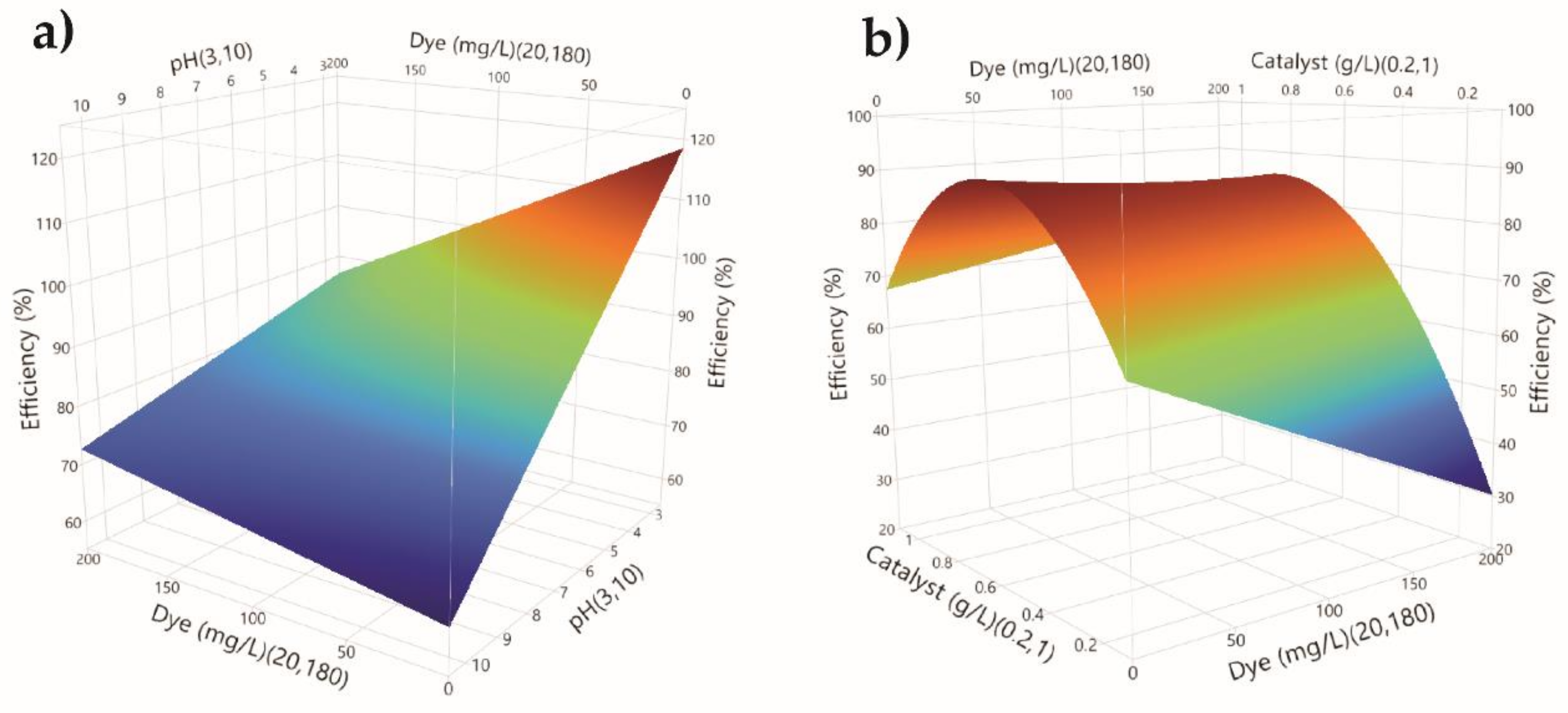
2.3.1. Response Area Diagrams

Diagrams of response surfaces for two-factor interactions (dye concentration and pH, dye concentration and catalyst concentration) are shown in Figure 6.
The interaction of dye concentration and pH values within photocatalytic degradation is illustrated in Figure 6a. If the dye concentration is at least 20 mg/L, the efficiency of the process will increase sharply with decreasing pH value. Therefore, pH controls the process to a significant extent. It can be concluded that photocatalytic performance is better in acidic conditions. According to Karimi-Shamsabadi et al. [56] and Shamsabadi and Behpour [57], the magenta dye molecule structure would be changed mostly into the quinone structure under acidic conditions, which is more prone to oxidation over the azo structure due to the sulfonic groups contributing to in hydrogen protons capture. For the above reasons, the photocatalytic performance reaches a maximum in acidic conditions, followed by a decrease in the pH > 6.5. At high pH values, the hydroxyl radicals are rapidly scavenged, and they do not react with dyes.
Additionally, the concentrations of the dye and the TiO2–Fe3O4 catalyst represent a significant two-factor interaction. At the highest dye concentration, the decolourisation efficiency will increase if the catalyst dose is increased (up to 0.6 g/L) (Figure 6b). Decolourisation efficiency decreases with further dye concentration increase. The increase in the initial dye concentration requires more active free radicals to enable efficient degradation, and more catalyst is required to maintain satisfying process efficiency. The obtained conclusion is consistent with the results reported in previous literature [58,59,60].
A further increase in the catalyst concentration causes a decrease in the efficiency of the photocatalytic degradation process. Namely, at lower catalyst dosages the absorbed light controls the activity of the photocatalyst and corresponds to the limited catalyst surface area. Lower catalyst loadings correspond to fewer active sites for absorption of photons present in the media, and a lot of light may be transmitted through the solution. Increasing the catalyst mass till an optimum value complete utilisation of photons and higher reaction rates can be observed. Increasing catalyst concentration will provide more reactive sites, and thus increases the number of hydroxyl radicals significantly, resulting in the enhancement of the decolourisation rate. On the other hand, with the excessive increase of the catalyst dosage photodegradation efficiency decreases probably due to scattering and turbidity effects, resulting in decreased light penetration on the surface of the photocatalyst and into the dye solution. These findings are in good correlation with the literature [61,62]. Therefore, the same effect of catalyst concentrations is achieved in the efficiency of the photocatalytic decolourisation process even at the lowest concentrations of magenta dye (20 mg/L), but its influence, in that case, is much weaker.

2.3.2. Process Optimisation

Despite the small number of scientific papers implementing DSD analysis as the main design of the experiment, it has been found that the capability and adaptability of JMP 13 software provide significant advances in process optimisation. The goal of this experimental design is to maximize the efficiency of dye decolourisation in relation to process conditions. The optimisation of process conditions was performed within the limits of the examined variables: 20 ≤ x1 ≤ 180, 3≤ x2 ≤ 10, 0.2 ≤ x3 ≤ 1 in order to obtain a combination of input parameter values that enables maximum decolourisation efficiency.
The optimisation diagram gives a clear insight into how the three process parameters affect the dependent variable, that is, the efficiency of photocatalytic decolourisation of the magenta dye. Figure 7 presents the optimal process conditions. It was found that decreasing the pH value increases the decolourisation efficiency, while at more neutral and basic values the decolourisation efficiency decreases. Decolourisation efficiency at neutral pH 6.5 reaches up to 85.07%.
Acidic pH values, in this case, pH value 3, have negative effects on the environment, therefore, it is necessary to neutralize effluents before releasing them into the recipient, which leads to additional chemical consumption. In order to overcome this problem, the potential effect of pH change to more neutral values was examined. The convenience of JMP 13 software is reflected in the fact that it offers the researcher the opportunity to vary the optimal values and thus gain insight into changing the efficiency of the monitored process, to further improve the operational conditions of the process.
The statistical model shown in Figure 7 has a high dye magenta decolourisation efficiency of 85.07% under the following optimal conditions: dye concentration of 100 mg/L, pH value 6.5, TiO2–Fe3O4 concentration 0.6 g/L.

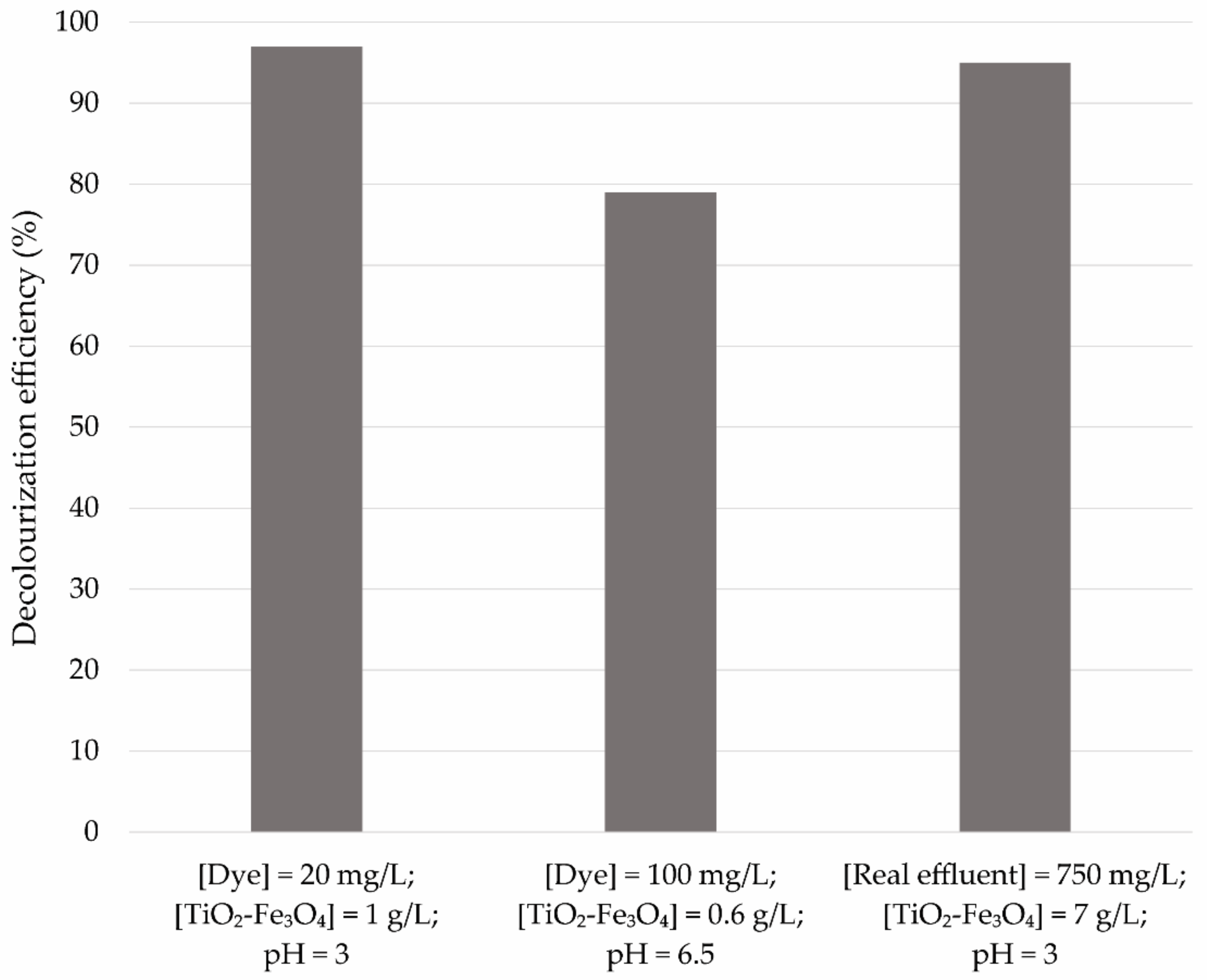
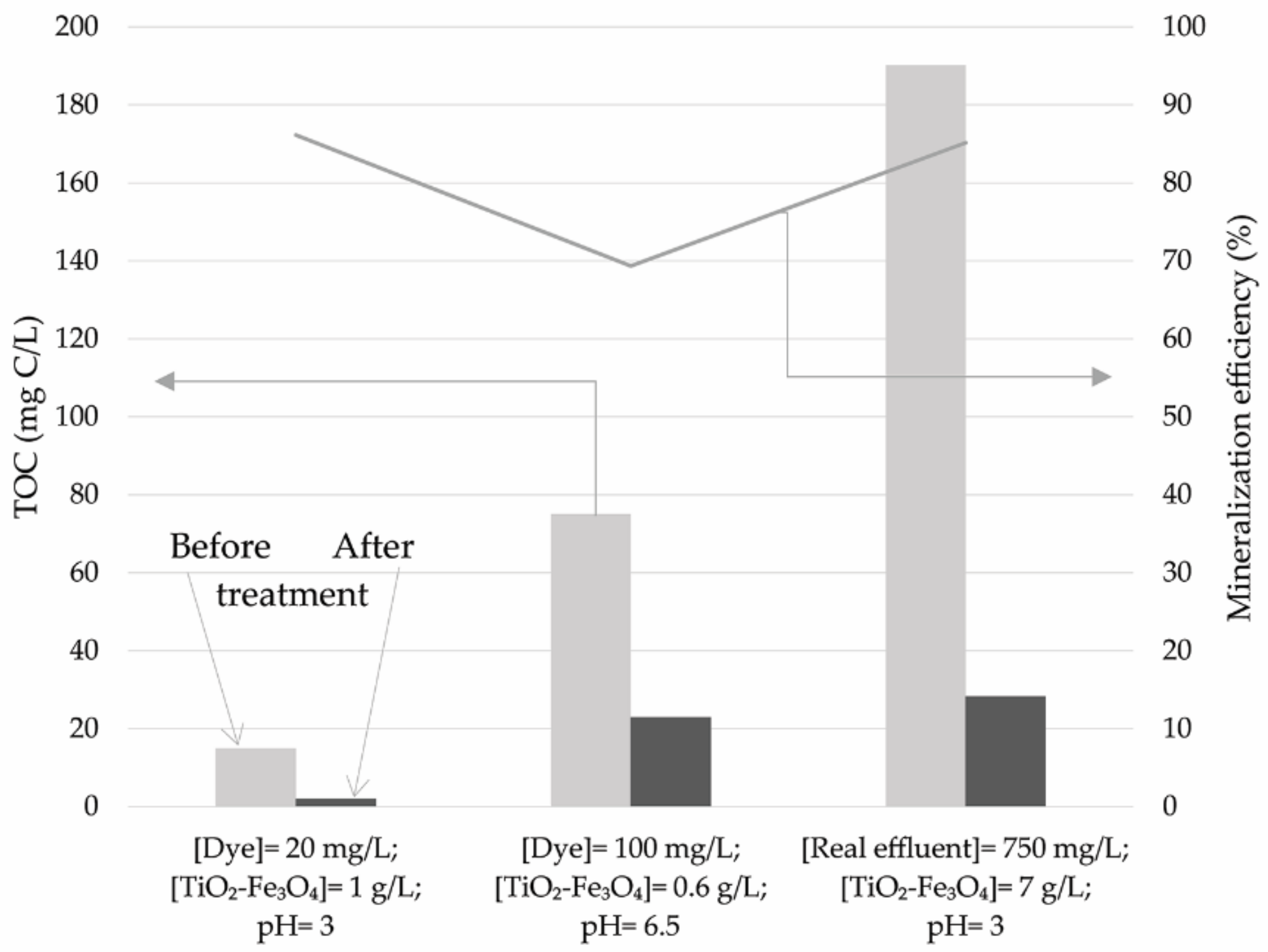
2.3.3. Mineralisation Efficiencies for Synthetic Dye Solution and Real Effluent

Decolourisation efficiencies were finally confirmed in three runs: conditions for maximal decolourisation efficiencies and optimal reaction conditions based on the DSD statistical method for synthetic dye solution and for real printing effluent (catalyst concentration was increased to follow the concentration of magenta dye in real effluent). Decolourisation efficiencies were 97, 79, and 95%, respectively (Figure 8). These results were in great correlation with results obtained during DSD modelling and the predicted optimal conditions.
In the same run, the total organic carbon (TOC) content was determined prior and after the process to evaluate mineralisation efficiency. Both TOC concentrations and mineralisation efficiencies are given in Figure 9.
Obtained results show that under acidic conditions and higher catalyst concentration both synthetic and real effluent reached almost the same mineralisation efficiencies. This indicates that the cleaning process of water-based dyes does not require the additional application of solvents or abrasives, which makes them effective, eco-friendly, and easy to use, contrary to highly volatile, fast-drying, solvent-based dyes. Working operators use only tap water and small amounts of detergents for the cleaning process of dye tank and rotating cylinder with flexible rubber relief plates. However, dye removal from printing effluent presents a necessity in order to preserve the environment.
Lower mineralisation efficiency under milder conditions indicates the formation of various by-products and intermediates, formed in solution during the process. This confirms that decolourisation of the dye does not always mean its mandatory complete oxidation into CO2 and H2O and implies the formation of long-lived by-products [63].

2.3.4. The Reusability of Photocatalytic Performance of TiO2–Fe3O4

In addition to photocatalytic performance, the stability of catalysts is also very important, especially from an economic perspective. The photocatalytic stability of TiO2–Fe3O4 was performed by reusing it, in a repeated photodegradation test. From Figure 10 it can be concluded that this photocatalyst is stable with no significant loss of photocatalytic activity.
It should be noted that, after each run, the applied catalyst was separated via an external magnetic field and washed with distilled water several times and dried at 105 °C for 2 h, and then annealed at 200 °C for 2 h. This is important to remove impurities, as the formation of by-products and their accumulation on the active surface sites of the catalyst will cause partial blockage of the pore system and cover its surface. Certainly, further repeating of this step will eventually cause a decrease in efficiency due to material scattering and photo corrosion.

3. Materials and Methods

In this work commercial TiO2 nanoparticles (Degussa P25 TiO2) were used for the synthesis of TiO2–Fe3O4. FeSO4 7H2O (p.a., POCH Poland S.A., Gliwice, Poland) and FeCl3 6H2O (POCH Poland S.A.) were used for the preparation of the Fe3O4 nanoparticles. Stock solutions of magenta dye were prepared by dissolving 14 g of the dye in 700 mL distilled water.

3.1. Synthesis of Fe3O4 Nanoparticles

Magnetic nanoparticles (Fe3O4) were prepared in a single-step process by conventional co-precipitation method, using Fe3+ and Fe2+ salts at a molar ratio of 2:1. Briefly, 100 mL of 0.2 M FeCl3 solution and 100 mL of 0.1 M FeSO4 solution was added into 500 mL baker and mixture was vigorously stirred. In order to optimize the pH value for precipitation of magnetite, 2 M NaOH solution was added dropwise to the solution, until the pH reached 10 and black precipitate was formed. The suspension was stirred vigorously for another 30 min afterwards the black precipitate of magnetite nanoparticles was separated from the suspension by an external magnet and washed repeatedly with distilled water until the pH of the supernatant was neutral. Collected Fe3O4 nanoparticles were dried at 105 °C for 4h (Figure 11a).

3.2. Synthesis of TiO2–Fe3O4 Catalyst

Modification of TiO2 with Fe3O4 nanoparticles was performed as follows: polycrystalline TiO2 (10 g) (Figure 11b) was dispersed in 100 mL of water and the suspension was sonicated for 30 min. Similarly, Fe3O4 nanoparticles (3 g) were dispersed in 100 mL of distilled water, and obtained suspension was also sonicated for 30 min. Afterwards, the suspension of Fe3O4 nanoparticles was gradually added to the suspension of TiO2 nanoparticles, and the mixture was stirred in an ultrasonic bath for 1h. Finally, the suspension was centrifuged and the resulting precipitate, TiO2–Fe3O4, was washed several times with distilled water and then dried at 110 °C for 4 h followed by annealing at 450 °C for 3 h (Figure 11c).

3.3. Characterisation of Nanoparticles

All three materials, TiO2, Fe3O4,and TiO2–Fe3O4, were characterised using different techniques and methods. Crystal structures of these materials were analysed by X-ray powder diffraction (Philips PW automated X-ray powder diffractometer (Cambridge, MA, USA)), with a focusing primary monochromator (CuKα radiation, λ = 1.5406 Å). The measurements were made in the 2θ range of 20–80°, with a step of 0.02° and an exposure time of 10 s per step. Identification of the compounds on the obtained diffractograms was carried out using the Pcpdfwin library, version 2.4 JCPDS-ICDD (Department of Physics, UNSPMF). Fourier transform infrared (FTIR) spectra were recorded by infrared spectrophotometer (FTIR Nexus 670, Thermonicolet, USA). The specific surface area of nanoparticles was measured by nitrogen adsorption using the Brunauer–Emmett–Teller (BET) method with an Autosorb TMiQ surface area analyser (Quantachrome, Boynton Beach, FL, USA). For sample preparation outgassing was performed with a final outgas temperature of 105 °C and an approximate outgas time of 15 h. Mesopore and micropore volumes were determined using the Barett–Joyner–Halender (BJH) method using desorption isotherm, and t-test method, respectively.

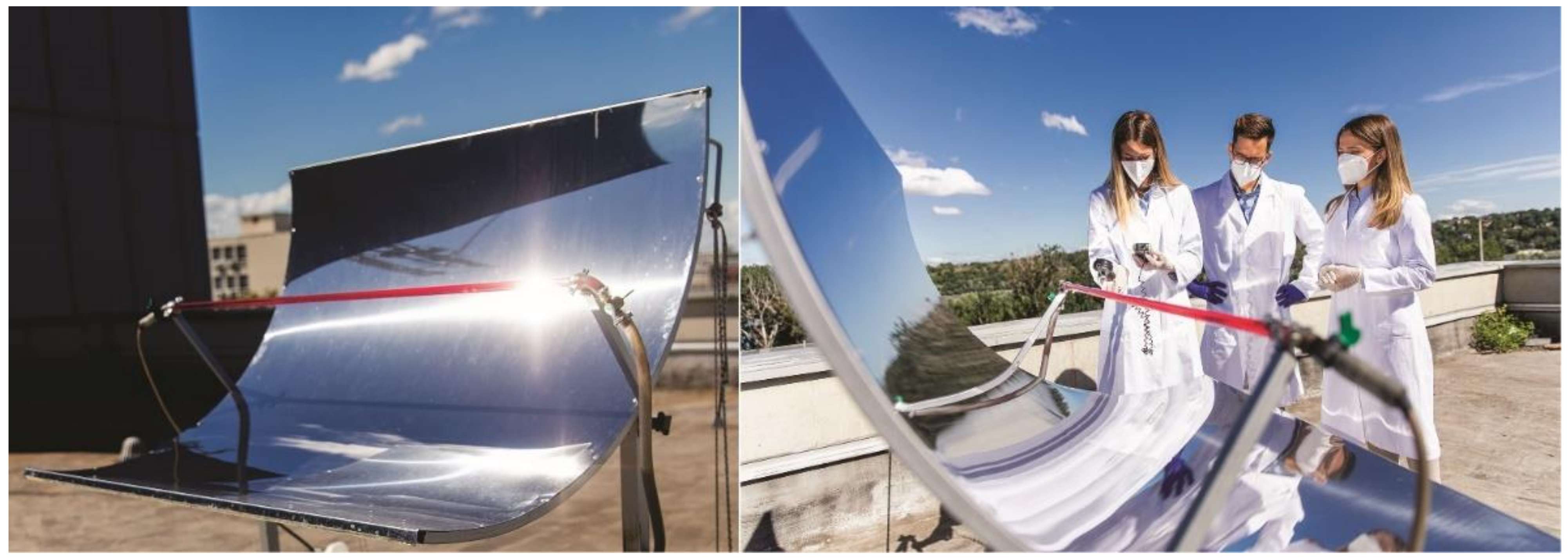
3.4. Parabolic Trough Concentrating Reactor

The experiments were performed in a parabolic trough concentrating reactor at continuous operation mode during the photocatalytic dye decolourisation process. The collector consists of a Pyrex glass absorber tube (length 129.70 cm, outer diameter: 1.86 cm, inside diameter: 1.26 cm), tracking mechanism, and concentrator reflective surface (length 129.70 cm, width of the parabola 113 cm, rim angle 90°). The reflector was made of a stainless-steel sheet. Solar radiation is reflected by the concentrator’s reflective surface and focused on the absorber tube. A constant radiation intensity of 1000 W/m2 (June/July period) was maintained, with the effluent being fully exposed to direct sunlight (Figure 12).
In order to ensure the continuous operation mode of the reactor, a pump (flow rate at about 50 mL/min) was connected which pumped the effluent into the reactor from the tank (1L) that contained effluent and the catalyst. The catalyst was maintained in solution by using a stirrer (200 rpm). After the reactor, the effluent was sent back to the tank from which it was returned to the reactor for final treatment. During the reaction in the reactor, temperatures reached approximately 50 °C. This is important to point out due to the fact that the activity of catalysts increases with an increase in reaction temperature. Moreover, the temperature range of 50–80 °C is regarded as the ideal temperature for effective photolysis of organic matter [64,65,66]. Moreover, the blank test (effluent without the catalyst) showed that developed temperature in the reactor had no significant effect on the decolourisation efficiency of magenta dye solution (decolourisation efficiency was 3%).
Decolourisation efficiency was determined immediately after ending the photo reaction (separation by external magnet), and measuring the absorbance of the aqueous solutions at 573 nm with a UV/VIS spectrophotometer (UV-1800 PG Instruments Ltd. T80+ UV/VIS, Kyoto, Japan). According to Equation (2), the decolourisation effciency was calculated:
Decolourization   % = A 0 A 1 A 0 × 100
where: A0 is the initial absorbance of the magenta aqueous solution sample before treatment and A1 is the absorbance of the sample after photocatalytic treatment.
In addition, determination of the total organic carbon (TOC) in the same samples was performed by varioTOC SELECT (Elementar, Langenselbold, Germany), with the method SRPS ISO 8245:2007 [67].

3.5. DSD Optimisation of the Photocatalytic Process

DSD analysis was used to examine the influence of three process parameters: initial dye concentration (20–180 mg/L), catalyst concentration in the photocatalytic process (0.2–1 g/L), and pH values (3–10). The range of investigated process parameters was determined based on previous research [53,68,69,70,71], as well as based on the determined dye concentration in a real effluent sample generated after the flexo printing process. Namely, the selected printing house generates and discharges a certain amount of wastewater into the recipient, whereby the amount of effluent and the concentration of dye (paint) varies daily depending on the dynamics of the production process, which also depends on the amount of clean water used for the cleaning process of the dye chamber and cylinder plates. For this reason, a wide range of initial dye concentrations was taken for the purposes of the research, while also taking into account the dye concentration determined in the effluent. The catalyst concentration was chosen in accordance with previous studies, in order to compare the effectiveness of selected catalysts applied to different media, originating from the textile and graphic industry [72].
Table 7 shows the levels of the investigated parameters (lower, middle, and upper) in order to identify the factors that cause a pronounced non-linear effect [54]. The selected software JMP 13 (SAS Institute, Cary, CA, USA) was used to generate the response surface diagram and complete statistical processing of the obtained results.
Working versions of regression models were adopted and experimental data were modelled using stepwise regression analysis, an iterative procedure in which independent variable regression equations are added or eliminated, in order to achieve one of the pre-adopted optimality criteria. Stepwise regression analysis included the main factors, their interactions, and quadratic factors, whereby statistical significance was considered for p values certain [55].

4. Conclusions

The focal point of this work is the fabrication of TiO2 photocatalyst modified with nano magnetite, and unique process design into a solar parabolic concentrating reactor in order to treat magenta effluent originating from the graphic industry. TiO2–Fe3O4 production procedure and DSD model, used for process optimisation, provided the following insights:
  • TiO2–Fe3O4 have a spherical shape and have a tendency to agglomerate. Good incorporation of magnetite and lower porosity and a determined composition indicate on higher catalytic activity potential.
  • The cubic spinel structure of magnetite attached to the surface of TiO2 was confirmed by XRD analysis, while both anatase and rutile titania phases were observed in both uncoated TiO2 and TiO2–Fe3O4.
  • Within the obtained results, all process parameters (dye concentration, catalyst concentration, and pH value) are significant, and two two-factor interactions were established: dye concentration-pH; dye concentration-catalyst concentration.
  • pH largely controls the process. Decreasing the pH value increases the decolourisation efficiency. In addition, the increase of catalyst concentration is favourable toward process efficiency, but only up to a certain value, while further increase leads to a decrease in efficiency.
  • Maximum decolourisation efficiency reached during optimisation is 95.6%.
  • Favouring milder process conditions and according to statistical modelling, decolourisation of magenta effluent of 85.07% is achieved following optimal conditions of dye concentration of 100 mg/L, TiO2–Fe3O4 concentration of 0.6 g/L, and pH of 6.5.
Obtained results indicate a good photocatalytic performance of TiO2–Fe3O4 in a solar parabolic concentrating reactor for graphic dye effluent decolourisation. As this is a sort of composite catalyst, ongoing research is directed towards using iron components in altered reactor configuration in selected processes. This would enable continuous wastewater treatment in both day and night mode, proving that this is a promising, superb catalyst in the wastewater treatment sector.

Author Contributions

G.P.M.: Investigation, Conceptualization, Writing—Original Draft; J.N.: Writing—Original Draft; Investigation, Data Curation; V.G.: Methodology, Formal analysis, Data Curation; A.K.M.: Formal analysis, Validation, Data Curation; J.A.: Writing—Review & Editing, Supervision; M.B.-T.: Writing—Review & Editing, Supervision; D.K.: Writing—Review & Editing, Resources, Project administration, Funding acquisition. All authors have read and agreed to the published version of the manuscript.

Funding

Research is funded by the Science Fund of the Republic of Serbia—Program for excellent projects of young researchers—PROMIS (WasteWaterForce Project 6066881).

Data Availability Statement

Not applicable.

Acknowledgments

Authors would like to thank Srđan Rakić, Department of Physics, Faculty of Sciences, Novi Sad, for his assistance in performing X-ray diffraction measurements, and Dušan Marčeta for reactor photographies.

Conflicts of Interest

The authors declare that they have no known competing financial interests or personal relationships that could have appeared to influence the work reported in this paper.

References

  1. Natarajan, S.; Bajaj, H.C.; Tayade, R.J. Recent advances based on the synergetic effect of adsorption for removal of dyes from waste water using photocatalytic process. J. Environ. Sci. 2018, 65, 201–222. [Google Scholar] [CrossRef] [PubMed]
  2. Karimifard, S.; Moghaddam, M. Application of response surface methodology in physicochemical removal of dyes from wastewater: A critical review. Sci. Total Environ. 2018, 640–641, 772–797. [Google Scholar] [CrossRef] [PubMed]
  3. Katheresan, V.; Kansedo, J.; Lau, S. Efficiency of various recent wastewater dye removal methods: A review. J. Environ. Chem. Eng. 2018, 6, 46764697. [Google Scholar] [CrossRef]
  4. Kanakarajua, D.; Shahdad, N.R.M.; Lim, J.C.; Pace, A. Magnetic hybrid TiO2/Alg/FeNPs triads for the efficient removal of methylene blue from water. Sustain. Chem. Pharm. 2018, 8, 50–62. [Google Scholar] [CrossRef]
  5. Chen, D.; Cheng, Y.; Zhou, N.; Chen, P.; Wang, Y.; Li, K.; Ruan, R. Photocatalytic degradation of organic pollutants using TiO2-based photocatalysts: A review. J. Clean. Prod. 2020, 268, 121725. [Google Scholar] [CrossRef]
  6. Zhao, X.; Zhang, G.; Zhang, Z. TiO2-based catalysts for photocatalytic reduction of aqueous oxyanions: State-of-the-art and future prospects. Environ. Int. 2020, 136, 105453. [Google Scholar] [CrossRef]
  7. Lee, S.Y.; Kang, D.; Jeong, S.; Do, H.T.; Kim, J.H. Photocatalytic Degradation of Rhodamine B Dye by TiO2 and Gold Nanoparticles Supported on a Floating Porous Polydimethylsiloxane Sponge under Ultraviolet and Visible Light Irradiation. ACS Omega 2020, 5, 4233–4241. [Google Scholar] [CrossRef]
  8. Reza, K.M.; Kurny, A.; Gulshan, F. Parameters affecting the photocatalytic degradation of dyes using TiO2: A review. Appl. Water Sci. 2017, 7, 1569–1578. [Google Scholar] [CrossRef]
  9. Hurum, D.C.; Agrios, A.G.; Gray, K.A. Explaining the Enhanced Photocatalytic Activity of Degussa P25 Mixed-Phase TiO2 Using EPR. J. Phys. Chem. B. 2003, 107, 4545–4549. [Google Scholar] [CrossRef]
  10. Wang, G.; Xu, L.; Zhang, J.; Yin, T.; Han, D. Enhanced Photocatalytic Activity of TiO2 Powders (P25) via Calcination Treatment. Int. J. Photoenergy 2012, 2012, 265760. [Google Scholar] [CrossRef] [Green Version]
  11. Qi, W.; Yang, Y.; Du, J.; Yang, J.; Guo, L.; Zhao, L. Highly photocatalytic electrospun Zr/Ag Co-doped titanium dioxide nanofibers for degradation of dye. J. Colloid. Interface Sci. 2021, 603, 594–603. [Google Scholar] [CrossRef] [PubMed]
  12. Nguyen, C.H.; Fu, C.C.; Juang, R.Y. Degradation of methylene blue and methyl orange by palladium-doped TiO2 photocatalysis for water reuse: Efficiency and degradation pathways. J. Clean Prod. 2018, 202, 413–427. [Google Scholar] [CrossRef]
  13. Chakhtouna, H.; Benzeid, H.; Zari, N. Recent progress on Ag/TiO2 photocatalysts: Photocatalytic and bactericidal behaviors. Environ. Sci. Pollut. Res. 2021, 28, 44638–44666. [Google Scholar] [CrossRef]
  14. Arias, M.; Aguilar, C.; Piza, M.; Zarazua, E.; Anguebes, F.; Anguebes, F.; Anguebes, F.; Anguebes, F.; Cordova, V. Removal of the Methylene Blue Dye (MB) with Catalysts of Au-TiO2: Kinetic and Degradation Pathway. Modern Res. Catal. 2021, 10, 106960. [Google Scholar]
  15. Khasawneh, O.F.S.; Palaniandy, P. Removal of organic pollutants from water by Fe2O3/TiO2 based photocatalytic degradation: A review. Environ. Technol. Innov. 2021, 21, 101230. [Google Scholar] [CrossRef]
  16. Jacinto, M.J.; Ferreira, L.F.; Silva, V.C. Magnetic materials for photocatalytic applications—A review. J. Sol-Gel Sci. Technol. 2020, 96, 1–14. [Google Scholar] [CrossRef]
  17. Panda, S.K.; Aggarwal, I.; Kumar, H.; Prasad, L.; Kumar, A.; ·Sharma, A.; ·Vo, D.V.N.; Thuan, D.V.; Mishra, V. Magnetite nanoparticles as sorbents for dye removal: A review. Environ. Chem. Lett. 2021, 19, 2487–2525. [Google Scholar] [CrossRef]
  18. Thomas, N.; Dionysiou, D.D.; Pillai, S.C. Heterogeneous Fenton catalysts: A review of recent advances. J. Haz. Mat. 2021, 404, 124082. [Google Scholar] [CrossRef]
  19. Li, Y.; Zhang, M.; Guo, M. Preparation and properties of a nano TiO2/Fe3O4 composite superparamagnetic photocatalyst. Rare Met. 2009, 28, 423–427. [Google Scholar] [CrossRef]
  20. Pang, Y.L.; Lim, S.; Ong, H.C.; Chong, W.T. Research progress on iron oxide-based magnetic materials: Synthesis techniques and photocatalytic applications. Ceram. Int. 2016, 42, 9–34. [Google Scholar] [CrossRef]
  21. Sunaryono, S.; Fitriana, D.R.; Novita, L.R.; Hidayat, M.F.; Hartatiek, H.; Mufti, N.; Taufiq, A. The effect of Fe3O4 concentration to photocatalytic activity of Fe3O4@TiO2-PVP core-shell nanocomposite. J. Phys. Conf. Ser. 2020, 1595, 012003. [Google Scholar] [CrossRef]
  22. Sun, L.; Zhou, Q.; Mao, J.; Ouyang, X.; Yuan, Z.; Song, X.; Gong, W.; Mei, S.; Xu, W. Study on Photocatalytic Degradation of Acid Red 73 by Fe3O4@TiO2 Exposed. Facets. Appl. Sci. 2022, 12, 3574. [Google Scholar] [CrossRef]
  23. Parast, F.; Montazeri-Pour, M.; Rajabi1, M.; Bavarsiha, F. Comparison of the Structural and Photo-catalytic Properties of Nanostructured Fe3O4/TiO2 Core-Shell Composites Synthesized by Ultrasonic and Stöber Methods. Sci. Sinter. 2020, 52, 415–432. [Google Scholar] [CrossRef]
  24. Gnanasekaran, L.; Hemamalini, R.; Rajendran, S.; Qin, J.; Lütfi Yola, M.; Atar, N.; Gracia, F. Nanosized Fe3O4 incorporated on a TiO2 surface for the enhanced photocatalytic degradation of organic pollutants. J. Mol. Liqid. 2019, 287, 110967. [Google Scholar] [CrossRef]
  25. Razip, N.I.M.; Lee, K.M.; LaI, C.W.; Ong, B.H. Recoverability of Fe3O4/TiO2 nanocatalyst in methyl orange degradation. Mater. Res. Express. 2019, 6, 075517. [Google Scholar] [CrossRef]
  26. Vinosel, V.M.; Janifer, M.A.; Anand, S.; Pauline, S. Structural and Functional Group Characterization of Nanocomposite Fe3O4/TiO2 and Its Magnetic Property Mechanics. Matter. Sci. Eng. J. 2017, 9, 1–7. [Google Scholar]
  27. Banisharif, A.; Hakim Elahi, S.; Anaraki Firooz, A.; Khodadadi, A.; Mortazavi, Y. TiO2/Fe3O4 Nanocomposite Photocatalysts for Enhanced Photo-Decolorization of Congo Red Dye. Int. J. Nanosci. Nanotechnol. 2013, 9, 193–202. [Google Scholar]
  28. Hasanpour, A.; Niyaifar, M.; Mohammadpour, H.; Amighian, J. A novel non-thermal process of TiO2-shell coating on Fe3O4-core nanoparticles. J. Phys. Chem. Solids 2012, 73, 1066–1070. [Google Scholar] [CrossRef]
  29. Jiang, W.; Zhang, X.; Gong, X.; Yan, F.; Zhang, Z. Sonochemical synthesis and characterization of magnetic separable Fe3O4–TiO2 nanocomposites and their catalytic properties. Int. J. Smart Nano Mater. 2010, 1, 278–287. [Google Scholar] [CrossRef]
  30. Dong, H.; Zeng, G.; Tang, L.; Fan, C.; Zhang, C.; He, X.; He, Y. An overview on limitations of TiO2-based particles for photocatalytic degradation of organic pollutants and the corresponding countermeasures. Water Res. 2015, 79, 128–146. [Google Scholar] [CrossRef]
  31. Nawsud, Z.A.; Altouni, A.; Akhijahani, H.S.; Kargarsharifabad, H. A comprehensive review on the use of nano-fluids and nano-PCM in parabolic trough solar collectors (PTC). Sustain. Energy Technol. Assess. 2022, 51, 101889. [Google Scholar] [CrossRef]
  32. Pucar Milidrag, G.; Becelic-Tomin, M.; Kulic Mandic, A.; Watson, M.; Kerkez, D. Scoping Review of Design and Applications of Parabolic Trough Collector (PTC). In Parabolic Troughs Design and Applications, 1st ed.; Sebastiaan, H., Ed.; Nova Science Publishers, Inc.: New York, NY, USA, 2020; pp. 1–30. [Google Scholar]
  33. Jones, B.; Nachtsheim, C.J. Definitive Screening Designs with Added Two-Level Categorical Factors. J. Qual. Technol. 2013, 45, 121–129. [Google Scholar] [CrossRef]
  34. Mohamed, O.A.; Masood, S.H.; Bhowmik, J.L. Investigation on the Flexural Creep Stiffness Behavior of PC–ABS Material Processed by Fused Deposition Modeling Using Response Surface Definitive Screening Design. J. Met. Mater. Miner. 2017, 69, 498–505. [Google Scholar] [CrossRef]
  35. Fidaledo, M.; Lavecchia, R.; Petrucci, E.; Zuorro, A. Application of a novel definitive screening design to decolorization of an azo dye on boron-doped diamond electrodes. Int. J. Environ. Sci. Technol. 2016, 13, 835–842. [Google Scholar] [CrossRef]
  36. Zhao, J.; Li, W.; Qu, H.; Tian, G.; Wei, Y. Application of definitive screening design to quantify the effects of process parameters on key granule characteristics and optimize operating parameters in pulsed-spray fluid-bed granulation. Particuology 2019, 43, 56–65. [Google Scholar] [CrossRef]
  37. Marami, M.B.; Farahmandjou, M.; Khoshnevisan, B. Sol–Gel Synthesis of Fe-Doped TiO2 Nanocrystals. J. Electron. Mater. 2018, 47, 3741–3748. [Google Scholar] [CrossRef]
  38. Thommes, M.; Kaneko, K.; Neimark, A.V.; Olivier, J.P.; Rodriguez-Reinoso, F.; Rouquerol, J.; Sing, K.S.W. Physisorption of gases, with special reference to the evaluation of surface area and pore size distribution (IUPAC Technical Report). Pure Appl. Chem. 2015, 87, 1051–1069. [Google Scholar] [CrossRef]
  39. AL-Othman, Z.A. Review: Fundamental Aspects of Silicate Mesoporous Materials. Materials 2012, 5, 2874–2902. [Google Scholar] [CrossRef]
  40. Bessergenev, V.G.; Mateus, M.C.; Botelho do Rego, A.M.; Hantusch, M.; Burkel, E. An improvement of photocatalytic activity of TiO2 Degussa P25 powder. Appl. Catal. A General 2015, 500, 40–50. [Google Scholar] [CrossRef]
  41. McNaught, A.D.; Wilkinson, A. IUPAC. Compendium of Chemical Terminology, 2nd ed.; Blackwell Scientific Publications: Oxford, UK, 1997. [Google Scholar]
  42. Alonso-Tellez, A.; Masson, R.; Robert, D.; Keller, N.; Keller, V. Comparison of Hombikat UV100 and P25 TiO2 performance in gas-phase photocatalytic oxidation reactions. J. Photochem. Photobiol. A Chem. 2012, 250, 58–65. [Google Scholar] [CrossRef]
  43. Lezner, M.; Grabowska, E.; Zaleska, A. Preparation and photocatalytic activity of iron- modified titanium dioxide photocatalyst. Physicochem. Probl. Miner. Process. 2012, 48, 193–200. [Google Scholar]
  44. An, X.; Cheng, D.; Dai, L.; Wang, B.; Ocampo, H.J.; Nasrallah, J.; Jia, X.; Zou, J.; Long, Y.; Ni, Y. Synthesis of nano-fibrillated cellulose/magnetite/titanium dioxide (NFC@Fe3O4@TNP) nanocomposites and their application in the photocatalytic hydrogen generation. Appl. Catal. B 2017, 206, 53–64. [Google Scholar] [CrossRef]
  45. Nijpanich, S.; Nimpaiboon, A.; Rojruthai, P.; Sakdapipanich, J. Hydroxyl-Terminated Saponified Natural Rubber Based on the H2O2/P25-TiO2 Powder/UVC-Irradiation System. Polymers 2021, 13, 1319. [Google Scholar] [CrossRef] [PubMed]
  46. Abbas, M.; Rao, B.P.; Reddy, V.; Kim, C.G. Fe3O4/TiO2 core/shell nanocubes:Single-batch surfactantless synthesis, characterization and efficient catalysts for methyleneblue degradation. Ceram. Int. 2014, 40, 11177–11186. [Google Scholar] [CrossRef]
  47. Scherrer, P. Bestimmung der Grosse und der Inneren Struktur von Kolloidteilchen Mittels Rontgenstrahlen, Nachrichten von der Gesellschaft der Wissenschaften, Gottingen. Math.-Phys. Kl. 1918, 2, 98–100. [Google Scholar]
  48. Nikić, J.; Tubić, A.; Watson, M.; Maletić, S.; Šolić, M.; Majkić, T.; Agbaba, J. Arsenic Removal from Water by Green Synthesized Magnetic Nanoparticles. Water 2019, 11, 2520. [Google Scholar] [CrossRef]
  49. Klekotka, U.; Zambrzycka-Szelewa, E.; Satuła, D.; Kalska-Szostko, B. Stability Studies of Magnetite Nanoparticles in Environmental Solutions. Materials 2021, 14, 5069. [Google Scholar] [CrossRef]
  50. Uddin, M.J.; Cesano, F.; Chowdhury, A.R.; Trad, T.; Cravanzola, S.; Martra, G.; Mino, L.; Zecchina, A.; Scarano, D. Surface Structure and Phase Composition of TiO2 P25 Particles After Thermal Treatments and HF Etching. Front. Mater. 2020, 7, 192. [Google Scholar] [CrossRef]
  51. Jung, K.Y.; Park, S.B.; Ihm, S.K. Linear relationship between the crystallite size and the photoactivity of non-porous titania ranging from nanometer to micrometer size. Appl. Catal. 2002, 224, 229–237. [Google Scholar] [CrossRef]
  52. Salamat, S.; Younesi, H.; Bahramifar, N. Synthesis of magnetic core–shell Fe3O4@TiO2 nanoparticles from electric arc furnace dust for photocatalytic degradation of steel mill wastewater. RSC Adv. 2017, 7, 19391–19405. [Google Scholar] [CrossRef]
  53. Kecić, V.; Kerkez, Đ.; Prica, M.; Lužanina, O.; Bečelić-Tomin, M.; Tomašević Pilipović, D.; Dalamciaj, B. Optimization of azo printing dye removal with oak leaves-nZVI/H2O2 system using statistically designed experiment. J. Clean. Prod. 2018, 202, 65–80. [Google Scholar] [CrossRef]
  54. Pereira, A.C.; Reis, M.S.; Leca, J.M.; Rodrigues, P.M.; Marques, J.C. Definitive Screening Designs and latent variable modelling for the optimization of solid phase microextraction (SPME): Case study—Quantification of volatile fatty acids in wines. Chemom. Intell. Lab. Syst. 2018, 179, 73–81. [Google Scholar] [CrossRef]
  55. Gabbay, R.S.; Kenett, R.S.; Scaffaro, R.; Rubinstein, A. Synchronizing the release rates of salicylate and indomethacin from degradable chitosan hydrogel and its optimization by definitive screening design. Eur. J. Pharm. Sci. 2018, 125, 102–109. [Google Scholar] [CrossRef] [PubMed]
  56. Karimi-Shamsabadi, M.; Behpour, M.; Kazemi Babaheidari, A.; Saberi, Z. Efficiently Enhancing Photocatalytic Activity of NiO-ZnO doped onto nanozeolite X by synergistic effects of p-n heterojunction, supporting and zeolite nanoparticles in photo-degradation of Eriochrome Black T and Methyl Orange. J. Photochem. Photobio. A Chem. 2017, 346, 133. [Google Scholar] [CrossRef]
  57. Shamsabadi, M.K.; Behpour, M. Fabricated CuO–ZnO/nanozeolite X heterostructure with enhanced photocatalytic performance: Mechanism investigation and degradation pathway. Mater. Sci. Eng. B 2021, 269, 115170. [Google Scholar] [CrossRef]
  58. Kerkez, Đ.; Tomašević Pilipović, D.; Kozma, G.; Bečelić-Tomin, M.; Prica, M.; Rončević, S.; Kukovecz, A.; Dalmacija, B.; Konya, Z. Three different clay-supported nanoscale zero-valen iron materials for industrial azo dye degradation: A comparative study. J. Taiwan. Inst. Chem. Eng. 2014, 45, 2451–2461. [Google Scholar] [CrossRef]
  59. Mady, A.H.; Baynosa, M.L.; Tuma, D.; Shim, J.J. Heterogeneous activation of peroxymonosulfate by a novel magnetic 3D γ-MnO2@ZnFe2O4/rGO nanohybrid as a robust catalyst for phenol degradation. Appl. Catal. B-Environ. 2019, 244, 946–956. [Google Scholar] [CrossRef]
  60. Tu, Y.; Shao, G.; Zhang, W.; Chen, J.; Qu, J.; Zhang, F.; Tian, S.; Zhou, Z.; Ren, Z. The degradation of printing and dyeing wastewater by manganese-based catalysts. Sci. Total Environ. 2022, 828, 154390. [Google Scholar] [CrossRef]
  61. Alijani, H.; Abdouss, M.; Khataei, H. Efficient photocatalytic degradation of toxic dyes over BiFeO3/CdS/rGO nanocomposite under visible light irradiation. Diam. Relat. Mater. 2022, 122, 108817. [Google Scholar] [CrossRef]
  62. Aghaei, M.; Sajjadi, S.; Keihan, A.H. Sono-coprecipitation synthesis of ZnO/CuO nanophotocatalyst for removal of parathion from wastewater. Environ. Sci. Pollut. 2020, 27, 11541. [Google Scholar] [CrossRef]
  63. Kecić, V. Investigation of Fenton-process application in the treatment of dye wastewater in printing industry. Ph.D. Thesis, Faculty of Sciences, University of Novi Sad, Novi Sad, Serbia, 2019. [Google Scholar]
  64. Chen, Y.W.; Hsu, Y.H. Effects of Reaction Temperature on the Photocatalytic Activity of TiO2 with Pd and Cu Cocatalysts. Catalysts 2021, 11, 966. [Google Scholar] [CrossRef]
  65. Yamamoto, A.; Mizuno, Y.; Teramura, K.; Shishido, T.; Tanaka, T. Effects of reaction temperature on the photocatalytic activity of photo-SCR of NO with NH3 over a TiO2 photocatalyst. Catal. Sci. Technol. 2013, 3, 1771–1775. [Google Scholar] [CrossRef]
  66. Molins, F.; Küpper, K.; Schweers, E. Water quality—Determination of total organic carbon content. Chem. Photo. Chem. 2021, 5, 381–389. [Google Scholar]
  67. Water Quality—Guidelines for the Determination of Total Organic Carbon (TOC) and Dissolved Organic Carbon (DOC) (2007) SRPS ISO 8245:2007, Adopted by the Institute for Standardization of Serbia by Decision No. 3026/12-52-01/2007 of 19 April 2007, Identical to the International Standard ISO 8245:1999. Available online: https://iss.rs/en/project/show/iss:proj:17618 (accessed on 13 July 2022).
  68. Haddad, M.; Regti, A.; Laamri, M.R.; Mamouni, R.; Sffaj, N. Use of Fenton reagent as advanced oxidative process for removing textile dyes from aqueous solutions. J. Mater. Environ. Sci. 2014, 5, 667–674. [Google Scholar]
  69. Carvalho, N.S.; Carvalho, M. Dye degradation by green heterogeneous Fenton catalysts prepared in presence of Camellia sinensis. J. Environ. Manage. 2017, 187, 82–88. [Google Scholar] [CrossRef]
  70. Kecić, V.; Kerkez, Đ.; Prica, M.; Rapajić, S.; Leovac Maćerak, A.; Bečelić-Tomin, M.; Tomašević Pilipović, D. Optimization of Cyan flexo dye removal by nano zero-valent iron using response surface methodology. J. Graph. Eng. Des. 2017, 8, 35–45. [Google Scholar] [CrossRef]
  71. Bakole, P.; Adekunle, A.; Govindwar, S. Enhanced decolorization and biodegradation of acid red 88 dye by newly isolated fungus, Achaetomiumstrumarium. J. Environ. Chem. Eng. 2018, 6, 1589–1600. [Google Scholar] [CrossRef]
  72. Kerkez, Đ.; Bečelić-Tomin, M.; Tomašević Pilipović, D.; Prica, M.; Kulić, A.; Dalmacija, B.; Watson, M. Usage of green synthesized nZVI for degradation of three different dye molecules. In Proceedings of the 15th International Conference of Environmental Science and Technology, Global Network for Environmental Science and Technology (Global-Nest), University of Aegean, Rhodes, Greece, 31 August–2 September 2017. [Google Scholar]
Figure 1. SEM images of (a) Fe3O4 (b) TiO2 and (c) TiO2–Fe3O4 and EDX of (d) TiO2–Fe3O4.
Catalysts 12 00986 g001
Figure 2. N2 adsorption–desorption isotherms of (a) Fe3O4 (b) TiO2 and (c) TiO2–Fe3O4.
Catalysts 12 00986 g002
Figure 3. XRD patterns of (a) Fe3O4, (b) TiO2 and (c) TiO2–Fe3O4.
Catalysts 12 00986 g003
Figure 4. FTIR spectra of Fe3O4 TiO2 and TiO2–Fe3O4.
Catalysts 12 00986 g004
Figure 5. Diagnostic diagrams: (a) Diagram of the dependence of the actual in relation to the predicted values of the dye decolourisation efficiency; (b) Normal distribution diagram; (c) Diagram of the deviation of the standardized residuals from the zero line.
Catalysts 12 00986 g005
Figure 6. Diagram of the response surface of statistically significant interactions: (a) dye concentration and pH; (b) dye concentration and catalyst concentration.
Catalysts 12 00986 g006
Figure 7. Photocatalytic process optimisation diagram.
Catalysts 12 00986 g007
Figure 8. Decolourisation efficiency verification for synthetic dye solution (maximal efficiency and optimal conditions) and real effluent (maximal efficiency conditions).
Catalysts 12 00986 g008
Figure 9. TOC concentrations and mineralisation efficiencies for synthetic dye solution (maximal efficiency and optimal conditions) and real effluent (maximal efficiency conditions).
Catalysts 12 00986 g009
Figure 10. Repeated photodegradation under optimal conditions.
Catalysts 12 00986 g010
Figure 11. (a) Fe3O4 nanoparticles (b) TiO2 nanoparticles (c) TiO2–Fe3O4.
Catalysts 12 00986 g011
Figure 12. Parabolic trough concentrating reactor.
Catalysts 12 00986 g012
Table 1. Characteristics of Fe3O4, TiO2 and TiO2–Fe3O4 nanoparticles.
ParametersFe3O4TiO2TiO2–Fe3O4
Specific surface area (m2/g) 39.152.155.2
Total pore volume (cm3/g)0.1390.9220.420
Mesopore volume(cm3/g)0.1380.9210.423
Micropore volume (cm3/g)0.01490.02120.0224
Pore size (nm)7.3435.117.1
Table 2. Functional group present in FTIR spectra of Fe3O4, TiO2, and TiO2–Fe3O4.
Wavenumber (cm−1)Functional GroupReference
3424–OH stretching vibration[4,43,44]
1635–O–H bending vibration
1383Ti–O–Ti bridging stretching modes[10]
694–Fe–O stretching vibration[45]
639
560
650Ti–O stretching[10]
Table 3. Design of experiments with achieved efficiencies (%) in decolourisation process of graphic magenta dye.
No.Dye (mg/L)pHCatalysts (g/L)Efficiency (%)
110010157.4
210030.283.8
31806.50.230.2
4206.5189.3
518030.690.3
620100.661.4
7180100.249.1
8203192.4
918010175.6
102030.284.3
111803193.04
1220100.251.7
131006.50.687.7
1410010155.4
1510030.281.5
161806.50.235.1
17206.5188.1
1818030.689.5
1920100.660.1
20180100.247.1
21203195.6
2218010172.8
232030.286.7
241803189.7
2520100.250.6
261006.50.686.2
271006.50.688.1
281006.50.687.9
Table 4. Selected regression model.
Descriptive FactorValue
R20.862
R2 adj0.814
AIC217.337
BIC219.327
RMSE8.417
Table 5. ANOVA and Lack off fit test.
SourceDF aSS bMS cF Parametar
Model821,955.4302744.43055.106
Error19946.26049.800Prob > F
C. Total2722,901.690-<0.0001
Lack of Fit51376.198275.240100,980
Pure Error1540.8852.726Prob > F
Total Error201417.083-0.083
a Number of freedom degrees, b Sum of squares, c Variance (mean value of squares).
Table 6. Estimated regression coefficients.
ParameterEstimated ValueStandard Errort ValueProbability > |t|
pH−15.2821.88221−8.12<0.0001
Catalyst (g/L)10.4621.882215.56<0.0001
Dye (mg/L) and pH7.34802.593582.830.0103
Dye (mg/L) and Catalyst (g/L)7.14772.339023.060.0062
Dye (mg/L)−4.3881.88221−2.330.0303
pH and Catalyst (g/L)−1.85772.33902−0.790.4364
Table 7. Process parameters with experimental levels.
VariableUnitEncoded ValueLevel
−10+1
Dye concentrationmg/Lx120100180
pH x336.510
Catalyst concentrationg/Lx20.20.61
Publisher’s Note: MDPI stays neutral with regard to jurisdictional claims in published maps and institutional affiliations.

