Article

An Iron-Doped Calcium Titanate Cocatalyst for the Oxygen Reduction Reaction

by
Lucia Mazzapioda
1,
Riccardo Renga
1 and
Maria Assunta Navarra
1,2,*
1
Department of Chemistry, Sapienza University of Rome, Piazzale Aldo Moro 5, 00185 Rome, Italy
2
Hydro-Eco Research Center, Sapienza University of Rome, Via A. Scarpa 16, 00161 Rome, Italy
*
Author to whom correspondence should be addressed.
Catalysts 2023, 13(1), 127; https://doi.org/10.3390/catal13010127
Submission received: 9 October 2022 / Revised: 28 December 2022 / Accepted: 3 January 2023 / Published: 6 January 2023
(This article belongs to the Section Electrocatalysis)

Abstract

:
The oxygen reduction reaction (ORR) is an important challenge in the development and large-scale distribution of energy conversion devices, especially low-temperature proton exchange membrane (PEM) fuel cells. In order to speed up the ORR kinetics and improve fuel cell performance, iron-doped calcium titanate (CTFO) is proposed as a cocatalyst. Fundamental physical and chemical characterizations by means of X-ray diffraction, infrared spectroscopy, and morphological and thermal analyses for the understanding of the functional features of the proposed materials were carried out. Composite catalysts containing different amounts of CTFO additive with respect to platinum (i.e., Pt:CTFO 1:0.5 and 1:1 wt:wt) were studied using a rotating disk electrode (RDE). Fuel cell tests were performed at 80 °C under 30% and 80% relative humidity. The best Pt:CTFO composite catalyst was compared to a bare Pt/C and a Pt/C:CaTiO3−δ 1:1 catalyst, revealing superior performances of the latter at high relative humidity fuel cell operation, as a combined result of an optimized electrolyte-electrode interface and improved ORR kinetics due to the inorganic additive.

1. Introduction

Considerable attention has been spent on low-temperature proton exchange membrane fuel cells (PEMFCs) due to their zero-pollutant emission, high power density, and high efficiency [1]. The fundamental component of a PEM fuel cell is the membrane electrode assembly (MEA), which comprises a polymer electrolyte membrane interposed between the anode and cathode electrodes. At the current stage in technology, platinum (Pt)-based materials and Nafion represent the standard catalysts and electrolytes, respectively [2,3].
On the one hand, Pt catalysts show high catalytic activity, high stability, and corrosion resistance under fuel cell operating conditions; on the other hand, the Nafion membrane provides high proton conduction and electronic insulation and may act as a physical barrier supporting the separation of reactant gases.
However, to guarantee good fuel cell performance, a high hydration level (100% RH) and high temperatures are required to promote Nafion proton conductivity and facilitate electrode reactions [4,5]. Nevertheless, a PEM fuel cell must maintain the right balance between the hydration level inside the cell and the water produced at the cathode side. Otherwise, the flow of gases to the electrode could be obstructed because of the waterlogged electrode phenomenon, contributing to the final cell resistance [6,7]. Consequently, the optimization of PEM fuel cell components, aiming to work at high temperatures and low relative humidity, becomes necessary [8]. Moreover, the commercialization of PEMFCs is impeded because of the high cost of the above-mentioned components; the highest contribution to the overall cost of the cell is provided by the platinum catalysts. The prohibitive cost and scarcity of Pt have pushed researchers to find alternative electrode materials without undermining the catalytic performance of the cell [9,10].
Major attention has focused on the oxygen reduction reaction (ORR), which is the main rate-determining step in these devices, causing a rise in fuel cell overpotentials [11,12,13]. A high loading of a noble metal is needed to achieve an efficient ORR.
One way to design an active oxygen cathode material is based on the modification of conventional Pt/C catalysts using appropriate non-noble metal oxides as cocatalysts and supports promoters in both acidic and alkaline PEMFCs [14,15,16]. Indeed, thanks to the outstanding advantages of metal oxide particles, such as higher corrosion resistance in the electrochemical environment of fuel cells and the ability to establish strong interactions with Pt catalysts, preventing the agglomeration of noble-metal particles, Pt usage has increased, and the activity of the electrochemical reaction has improved [17,18].
Out of the numerous potential non-noble metal electrocatalysts, La-based perovskite oxides (with a general structure of LaMO3) appear as promising materials to catalyze the oxygen reduction reaction in alkaline environments [19,20,21]. Suntivichand and co-workers examined a series of perovskites in terms of their electronic structure and ORR performance, demonstrating that tuning their surface electronic structure features, such as transition-metal eg-filling, is a promising strategy in developing highly active non-precious-metal-containing perovskite oxide catalysts for oxygen reductions in electrochemical conversion and storage devices [22]. Indeed, it was demonstrated that inorganic perovskite oxides, which generally have lower ORR activity and accommodate partial substitution (e.g., A1−xA′xB1−yB′yO3), could introduce oxygen vacancies, changing the valence states of the metal cations and the surface chemistry of the oxide, providing a substantial electrocatalytic performance improvement [23,24,25]. However, it was experimentally found that some perovskites with identical eg possessed different intrinsic ORR performances, which suggests that other factors, such as the covalency of the B–O bond, also affect the intrinsic ORR activity of perovskite oxides. In particular, the B-site is also thought to be the main active site which proceeds on perovskite oxides in a reverse process with the ORR [26,27].
At present, most electrocatalysts with a perovskite structure may only be active as catalysts for alkaline fuel cells and water electrolyzers, showing promising ORR and OER activity; in an acidic environment, the results are unstable. Very few examples of perovskites with high OER/ORR activities in acid media exist [28,29,30].
Therefore, the search for an efficient and durable perovskite catalyst under a wide pH range is a great challenge due to the consideration of safety and cost.
In our previous work, an improved ORR activity was achieved using a low-cost sub-stoichiometric calcium titanate perovskite (CaTiO3−δ, CTO) as a Pt-oxide promoter [31,32]. The enhanced performance obtained with the CTO addition was considered to be due not only to the strong interaction between Pt and the oxide particles but also to the better stability and durability of the composite catalysts. Furthermore, the presence of oxygen vacancies in the oxide lattice could act as active sites that absorb oxygen, promoting the ORR’s kinetics.
As mentioned above, the doping of a B-site metal could effectively adjust the eg filling of perovskite oxides, enhancing their electrochemical performance. In this regard, several studies demonstrated that the presence of Fe in the B-site of perovskite oxides has favorable effects on their activity and stability in alkaline media [33,34,35].
Taking inspiration from these findings, herein, we report a study on an iron-doped calcium titanate perovskite used as a cocatalyst of Pt for the ORR. The substitution of the Ti4+ with iron could maximize the defects’ structure, enhancing the oxygen ion vacancies and electron-hole concentrations and becoming a promising mixed ionic and electronic conducting material. Furthermore, this type of perovskite was studied for oxygen transport membranes, demonstrating an improvement in oxygen surface exchange [36,37,38]. To the best of our knowledge, a study about an iron-doped calcium titanate perovskite used as a catalyst or cocatalyst of Pt for the ORR in acidic media is not yet reported.

2. Results

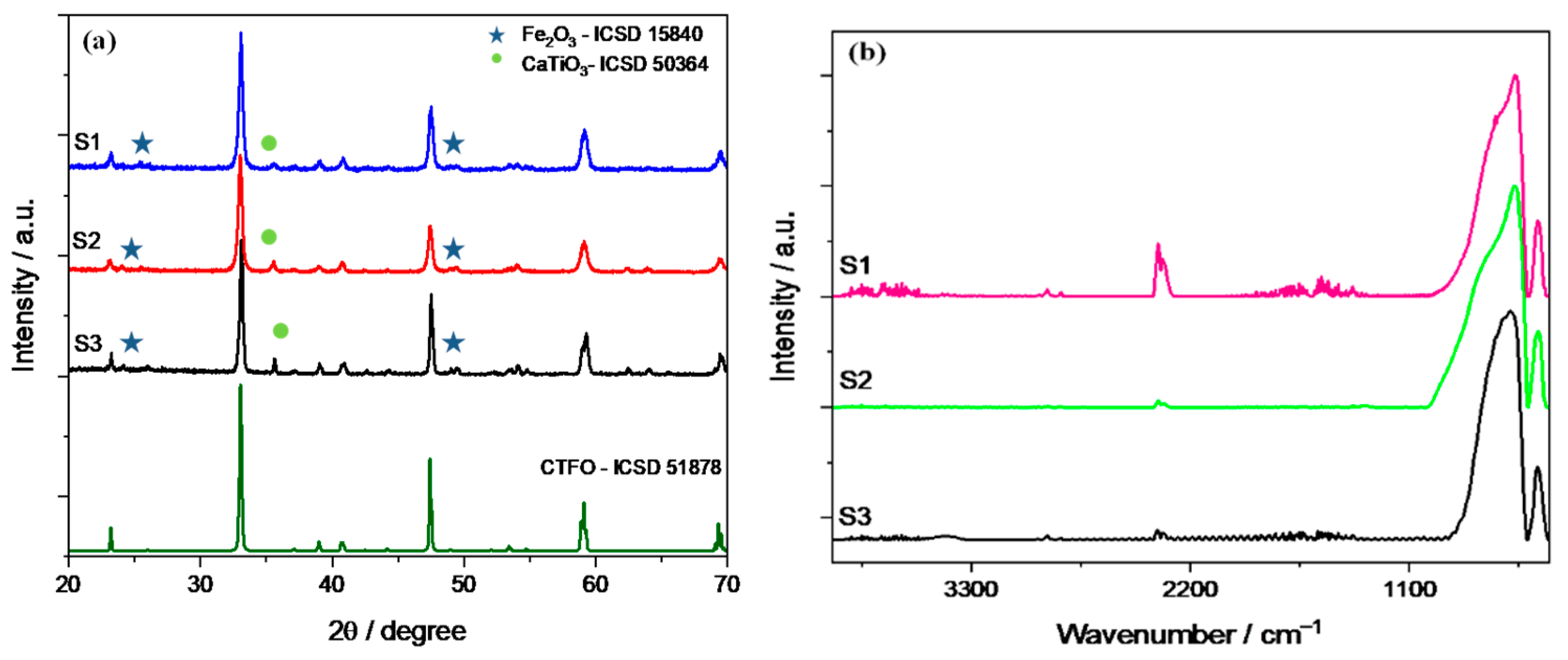
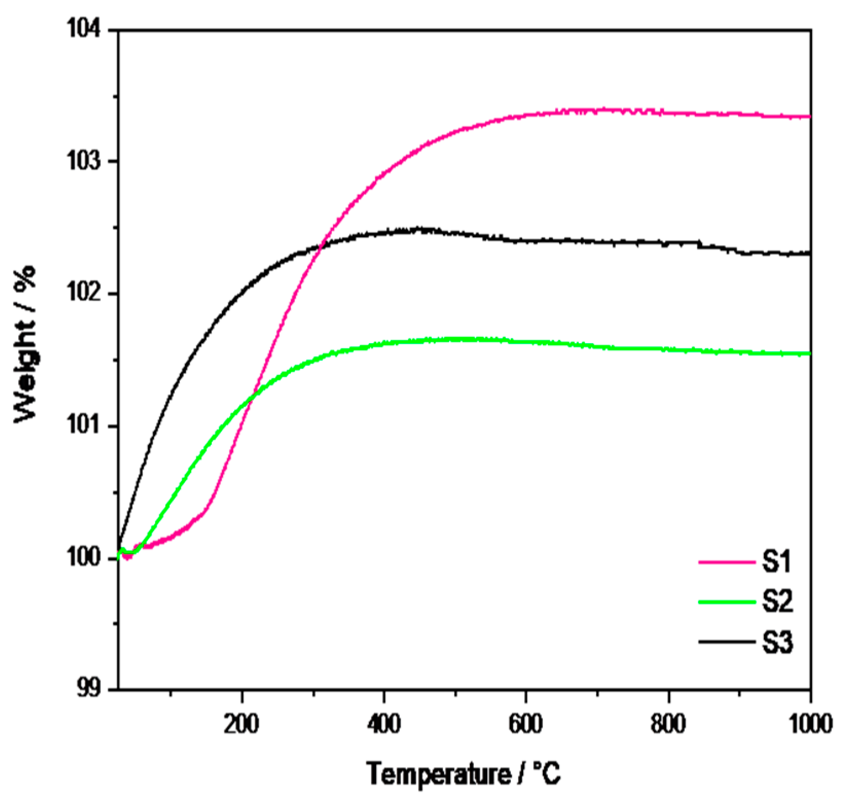
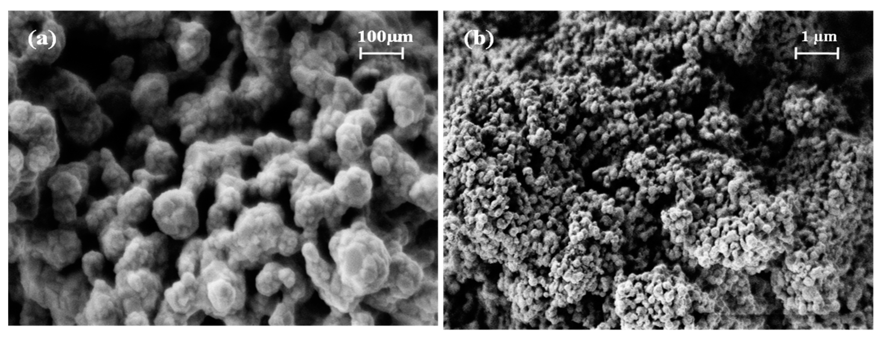
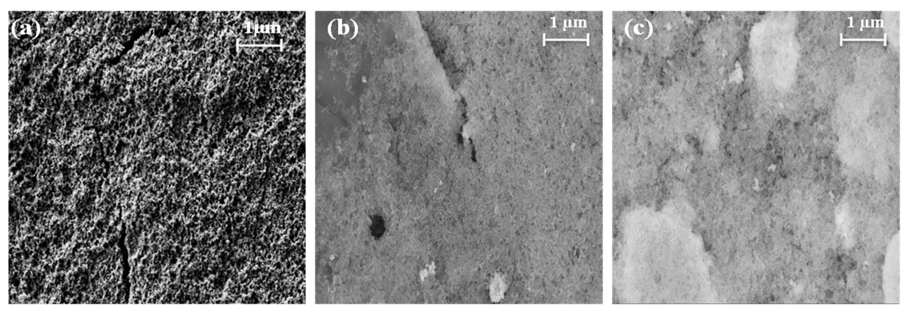
2.1. Physicochemical Characterization

Three samples of Fe-doped CaTiO3 (CaTi1−xFexO3−δ, CTFO) were prepared with dry high-energy ball milling. In all the syntheses, calcium carbonate CaCO3 (Sigma Aldrich, Merck KGaA, Darmstadt, Germany, ≥99.0%) and titanium(IV) oxide TiO2 (Sigma Aldrich, 99.5%) were used as the raw materials, whereas iron oxide Fe2O3 (Sigma Aldrich) was used as an iron precursor only in the first procedure (S1, according to specifications provided in Table 1). In order to increase the effectiveness of milling to obtain a pure CTFO, Fe2O3 was replaced with iron(III)oxide-hydroxide FeO(OH) (Sigma Aldrich). In all the milling procedures, the powders were mixed for 4 h at 25 Hz with a mass weight based on stoichiometric calculations to obtain the desired CaTi1−xFexO3−δ compound. Subsequently, the milled powder was calcined at 1100 °C for 5 h with a heating rate of 3 °C/min in the air [39]. Only in one procedure (S3, according to specifications provided Table 1) was the powder calcined at 800 °C for 5 h in an argon atmosphere to improve the CTFO purity and reduce the crystallite size of the sample.
The synthesis procedures are summarized in Table 1, where the purity and the average crystallite size for each CTFO sample, derived from the XRD studies, are also reported.
Figure 1a displays the XRD patterns of the three synthesized CaTi0.8Fe0.2O3−δ (CTFO) samples. The presence of an orthorhombic CTFO characterized by the Pnma space group was confirmed in all samples. The pattern in dark green corresponds to the CaTi1−xFexO3−δ reference ICSD-51878. As minor components, iron oxide Fe2O3 (ICSD-15840) and calcium titanate perovskite CaTiO3 (ICSD-50364) were found, as reported in Table 1.
These samples were also characterized using infrared spectroscopy, as shown in Figure 1b. Prior to the measurement, the samples were dried at 80 °C overnight in order to remove any physisorbed water. All spectra were normalized to the intensity of the Ti-O peak placed at 570 cm−1.
In Figure 1b, the typical bands corresponding to CaTiO3 due to the stretching of Ti-O and bending vibration of O-Ti-O are recognized at 570 and 450 cm−1, respectively [40]. The absorption bands attributed to the bending vibrations of O-Fe-O and stretching of the FeO3 groups in the perovskite structure are placed at frequencies of 508 cm−1 and 488 cm−1 [41], but these peaks are overlapped with those of the perovskite structure. The only significant change appears in the shape of the Ti-O stretching band; in particular, the S3 sample shows a roundish shape of this peak with respect to the other CTFO perovskites. This behavior could be attributed to the increase in the bending energy resulting from a reduction in B-site ordering in the perovskite structure due to the Ti4+ substitution with Fe3+ [42]. Therefore, a change in the crystal symmetry due to more effective doping in the S3 sample was observed, confirming the XRD results.
The thermal stability and the O2 adsorptive capacity of the oxides were evaluated using a thermogravimetric analysis under air (80 mL/min) in a temperature range between 25 °C and 1000 °C.
Figure 2 shows the TGA curves for the CaTi1−xFexO3−δ materials, where a weight gain is observed for each sample. This behavior was also previously observed in CaTiO3−δ oxides [31] and was related to the incorporation of oxygen thanks to the presence of the oxygen vacancies into the unit cell of the perovskite structure.
In detail, the S1 sample exhibits the highest incorporation of oxygen (3%), followed by the S3 (2%) and S2 samples (1.5%). Moreover, the S1 sample showed a temperature-dependent sorption kinetic, with a more rapid weight increase above 200 °C, as evident from the slope change of the curve. Conversely, the S2 and S3 samples started absorbing oxygen quite rapidly from room temperature, reaching a steady state at 251 °C for the S2 sample and 255 °C for the S3 sample, respectively. Based on the composition of the S1 sample (reported in Table 1), we could suppose that the O2 sorption process is positively influenced by the major amount of CTO (22%), which probably emphasizes the presence of oxygen vacancies in the perovskite lattices. On the contrary, the S2 and S3 samples presented a lower oxygen sorption capacity due to a reduced amount of the CTO phase. However, the S3 sample exhibited higher O2 sorption with respect to the S2 sample, most likely due to the structural effect related to the pure relative concentration of the CTFO phase.
Considering the promising features of the S3 perovskite in terms of purity and oxygen adsorption capacity, the S1 and S2 samples were excluded from further assessments.
The morphology of the S3 sample was revealed with the SEM analysis and recorded using two different magnifications, as shown in Figure 3. From the images, it is difficult to identify individual particles. Nonetheless, uniform, irregularly shaped pores were observed.
In order to figure out the relative distribution of the elements in the S3 powder, element mapping was carried out and reported in Figure 4. According to these results, the uniform distribution of Fe in the calcium titanate compound is clearly visible, confirming the effectiveness of iron doping.

2.2. Ex Situ Characterization of the Catalyst Inks

The composite catalysts were prepared by mixing the Pt/C and CTFO powders in a weight ratio of 1:0.5 and 1:1, and the catalytic inks were obtained according to the procedure reported in the experimental section. After being deposited on the glassy carbon electrode surface, SEM images of the catalyst inks were taken before the electrochemical characterizations to analyze the particle distribution and morphology of the ink deposition. As reported in Figure 5, the Pt/C sample results are more uniformly distributed and homogeneous with respect to both composite inks. The presence of CTFO renders the ink surface more compact and bright, being this latter effect due to the lower conductivity of CTFO compared to platinum. In addition, in the Pt/C:CTFO 1:1 ink, particle agglomeration is clearly visible.
The CV curves recorded after the conditioning procedure for all the investigated catalysts are shown in Figure 6, where hydrogen adsorption/desorption processes, with their corresponding platinum redox reactions, are observed in the low potential range. In order to preliminarily evaluate the catalytic activity of our samples, the electrochemically active surface area (ECSA) was calculated. Specifically, the ECSA values were derived by integrating the H-adsorption peaks in the 0.4–0.05 V vs. RHE potential range, corrected for the double-layer charging contribution [43].
As reported in Table 2, among all the CTFO-added catalysts, the Pt/C:CTFO 1:1 composition exhibited higher ECSA values (80 m2 g−1) with respect to the Pt/C (71 m2 g−1) and other composite electrode, Pt/C:CTFO 1:0.5 (65 m2 g−1). This result could be justified considering either the good electronic conductivity of the CTFO additive or the presence of oxygen vacancies that allowed the metal-oxide itself to exhibit active catalytic sites, as explained in our previous work for the CTO additive [31]. However, by comparing both perovskite-added catalysts, a more clearly visible hydrogen adsorption/desorption process occurred when the CTFO was mixed with Pt. We could assume that the small CTFO particles obtained via the solid-state reaction could provide optimized interactions between the platinum clusters and CTFO particles, which led to the enhanced surface area of the composite catalysts. Indeed, by comparing the ECSA values obtained for the Pt/C:CTO 1:1 catalyst with the Pt/C:CTFO 1:1 sample, the ECSA of the Pt/C:CTFO 1:1 catalyst was higher (80 m2 g−1) than the other composite Pt/C:CTO 1:1 catalyst (74 m2 g−1) [31]. The so-called strong metal−support interaction, which provides an enhancement of the catalytic activity of Pt, was also demonstrated by numerous researchers [44,45,46,47]. This phenomenon is correlated to the degree to which the support could act as an electron donor with the consequence of a shift of its d-band center [48].
Furthermore, the agglomeration of CTFO particles found with the SEM images did not seem to interfere with the Pt utilization. However, the Pt/C:CTFO 1:0.5 catalyst showed a lower ECSA value compared to the other composite ink, revealing that a poor amount of additive could not be sufficient to optimize the Pt accessibility and utilization and consequently improve the Pt/C catalytic activity.
Finally, both carbon corrosion and platinum nanoparticles dissolution processes, responsible for the catalytic activity loss when the fuel cell was working, might be mitigated when adding a metal oxide [49]. Therefore, the electrocatalytic properties of composite electrodes are expected to improve, increasing the amount of the inorganic additive.
The oxygen reduction reaction (ORR) activity was examined using rotating disk electrode (RDE) experiments at different rotation speeds in O2-saturated 0.1 M HClO4. Figure 7a shows a comparison of the LSV curves recorded at 1600 rpm for the three catalyst compositions, revealing an appreciable enhancement of the ORR activity in terms of a higher reductive limiting current achieved for the composite catalysts with respect to the reference Pt/C sample.
From the curves in Figure 7a, except for slight differences, the onset potential (Eons) and the half-wave potential (E1/2) resulted in approximately 0.9 V and 0.82 V, respectively, for all samples. However, the Pt/C:CTFO 1:1 catalyst displayed the largest jd value (−6.3 mA cm−2) associated with mass transport with respect to the Pt/C sample. The other composite catalyst, Pt/C:CTFO 1:0.5, exhibited a limiting current density comparable with the Pt/C catalyst, confirming that a lower amount of additive could not be sufficient to promote an improvement in Pt/C performance. However, contrary to what was claimed above for the ECSA, a non-doped CTO additive had a little stronger effect on the ORR activity with respect to CTFO. Indeed, Pt/C:CTO 1:1 delivered a jd of −7 mA cm−2 [31]. Most probably, the presence of some impurities, such as iron oxide, in the pristine CTFO sample could affect the oxygen adsorption/reduction capacity of the composite CTFO-based catalysts.
The number of electrons transferred in the ORR process for all the ink compositions was calculated using the Koutecky-Levich equation in the diffusion-controlled region at E = 0.3 V vs. RHE. As expected, these plots are linear with a non-zero intercept, indicating that the kinetic limitations were not derived from the slow charge diffusion of oxygen through the catalytic film; otherwise, they would result in non-linearity [50]. The number of electrons exchanged during the ORR was estimated for the three catalytic systems and reported in Figure 7b. The oxygen reduction reaction could occur via two pathways: the direct four-electron transfer pathway from O2 to H2O and the two-electron transfer pathway from O2 to hydrogen peroxide.
As shown in Figure 7b, the number of electrons exchanged during the oxygen reduction was 3.6 for Pt/C, 3.8 for Pt/C:CTFO 1:0.5, and 4 for Pt/C:CTFO 1:1. Despite the presence of impurities and particle agglomerations, the Pt/C:CTFO 1:1 composition showed perfect ORR performance with a four-electron pathway, whereas the other samples seemed to be less efficient towards the desired pathway. This could be explained considering the presence of oxygen vacancies on the CTFO lattice. Indeed, it was demonstrated that the presence of oxygen defects could change the surface chemistry and the electronic structure of a perovskite oxide, promoting charge transfer in the ORR and enabling the perovskite oxide to have high oxygen ion mobility [51]. The presence of oxygen vacancies and the ability of the CTFO particles to adsorb oxygen molecules were demonstrated with the TGA analysis. As a consequence, these new oxygen adsorption sites on the perovskite oxide surface could act as active catalytic sites, facilitating the oxygen reduction reaction. These results, in accordance with the ECSA values reported in Table 2, recognize the composite Pt/C:CTFO 1:1 sample as the most active catalyst among those investigated here.

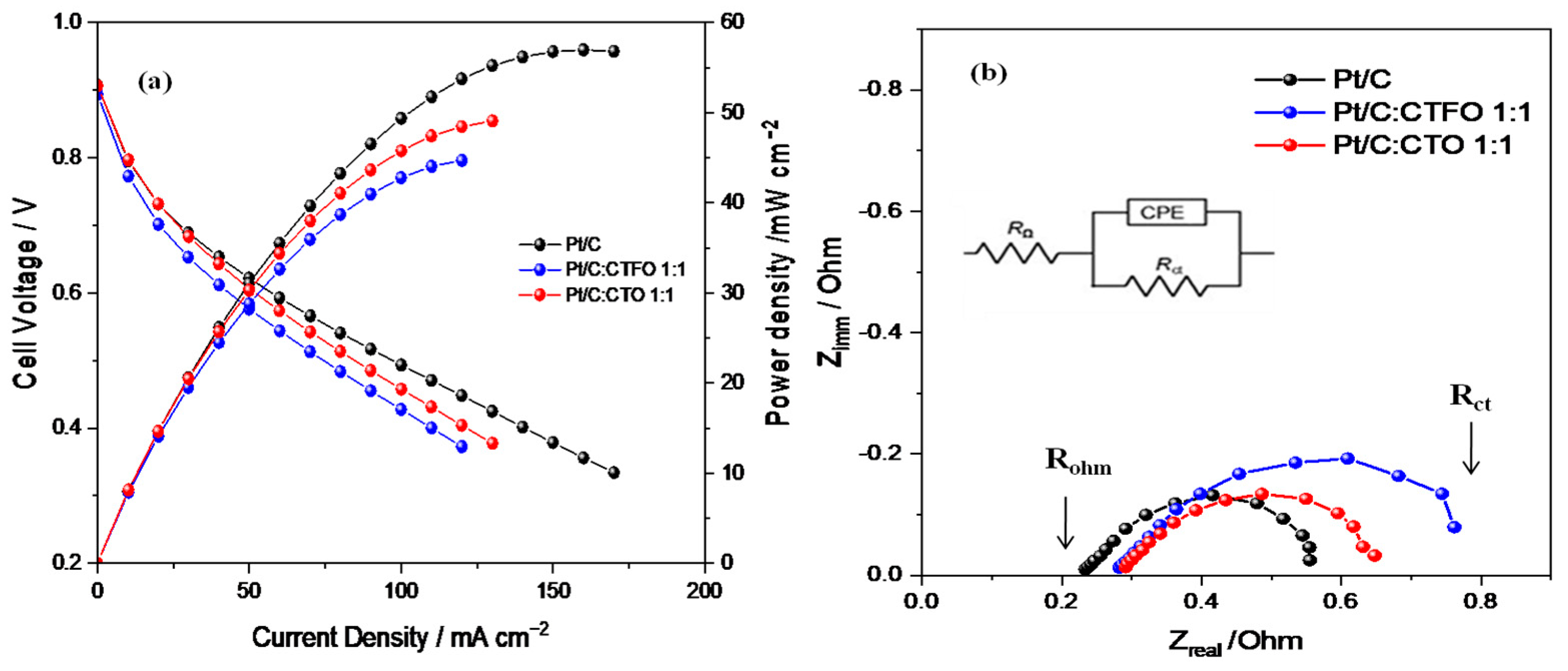
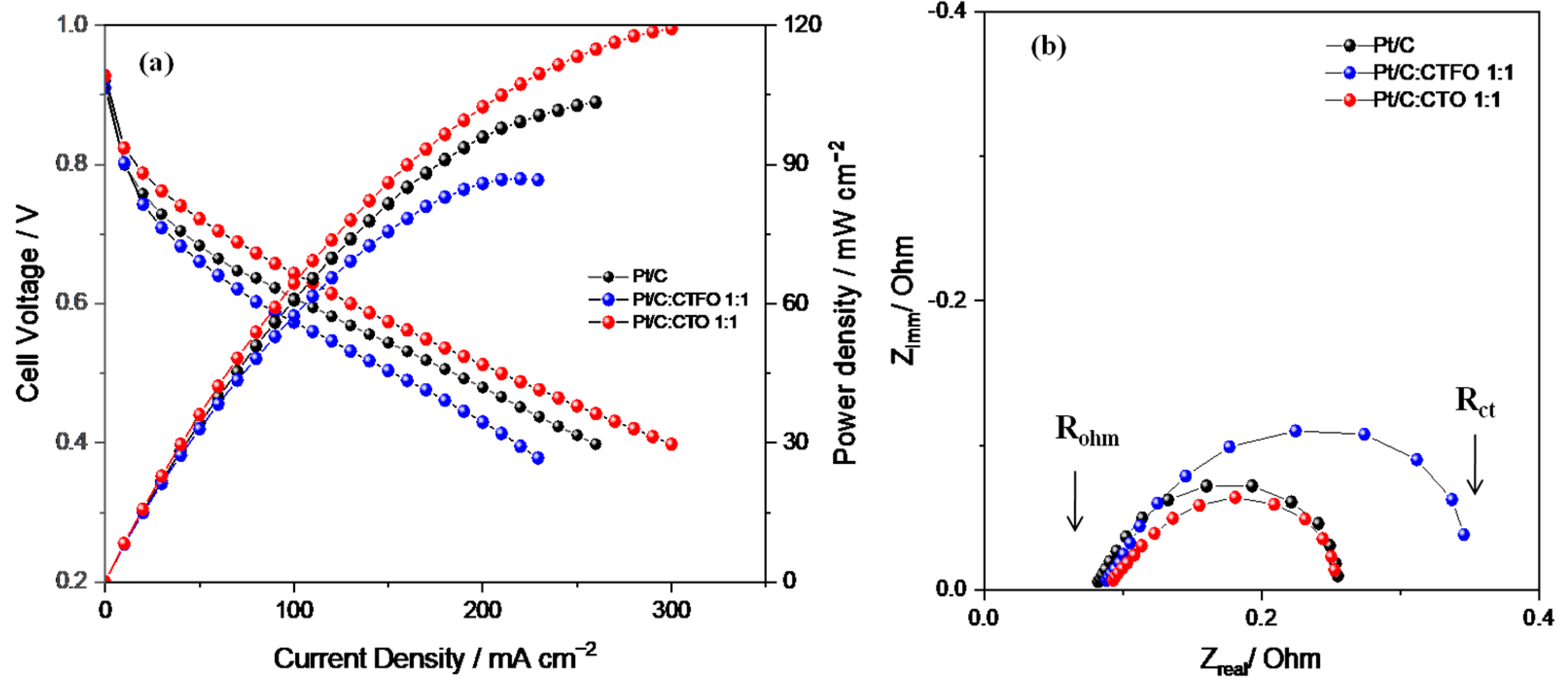
2.3. Fuel Cell Tests

Based on the results above, the Pt/C:CTFO 1:1 composite catalyst was selected to be used as the active cathode component in a PEM fuel cell, maintaining the same weight ratio between Pt and CTFO used for the RDE analysis. For the sake of comparison, a bare Pt/C catalyst was also studied. The PEMFC performances were evaluated under desirable practical conditions by recording the polarization and power-current curves at 80 °C and two relative humidity (RH) levels of 30% and 80%. To better investigate the effect of iron doping on the perovskite activity towards the ORR, the fuel cell performances of the Pt/C:CTFO 1:1 composite catalyst were compared with those of a membrane-electrode assembly (MEA) equipped with a Pt/C:CaTiO3−δ 1:1 cathodic catalyst (with the same Pt loading). It should be noted that CaTiO3−δ (CTO) was previously studied as a cathode additive in a direct methanol fuel cell (DMFC), showing a 40% increase in power density compared with the benchmark Pt/C catalyst at a high temperature (90 °C) [32].
As reported in Figure 8a, better fuel cell performances were obtained at 80 °C and 30% RH with the Pt/C-based MEA in terms of the maximum current and power densities delivered. By comparing the behaviors of both composite catalysts, the Pt/C:CTFO 1:1-based MEA showed a higher loss of potential in all regions of the polarization curve. These findings are in contrast with the results of the RDE experiments, confusing the hypothesis that the presence of CTFO particles at the cathode side could promote the kinetics of the ORR. The Pt:CTO1:1-based MEA exhibited a performance comparable with that of the Pt/C catalyst only at low current density, whereas at a higher current density, superior over-potentials were found.
To better elucidate the different fuel cell performances, the power densities delivered by each cell at specific current densities of 10, 50, and 100 mA/cm2 were compared. The power densities delivered at 10 mA/cm2 were 7.96 mW cm−2, 7.89 mW cm−2, and 8.13 mW cm−2 for the Pt/C, Pt/C:CTFO, and Pt:CTO-based MEAs, respectively. Despite the small differences, these values suggest lower overpotentials for the Pt:CTO-based MEA, confirming the positive role of the CTO perovskite as a promoter for the ORR. At 50 mA cm−2 the power densities delivered were 31.07 mW cm−2, 28.79 mW cm−2, and 30.30 mW cm−2 for the Pt/C-, Pt/C:CTFO-, and Pt:CTO-based MEAs, respectively. Here, the composite Pt/C:CTFO catalyst decreased its performance with respect to Pt, and an enhanced electrode/electrolyte impedance was observed from the EIS results, as reported in Figure 8b and Table 3. At 100 mA cm−2, the cell based on the Pt/C MEA showed a strong increase in performance with respect to the other samples, delivering a power density of 49.35 mW cm−2, whereas 45.76 mW cm−2 and 42.77 mW cm−2 were obtained for the Pt:CTO and Pt/C:CTFO-based MEAs, respectively.
These aspects are highlighted by the Nyquist plots of the impedance spectra, recorded during fuel cell operation and reported in Figure 8b. The spectra of all these samples were fitted by using the equivalent circuit R(CPE-Rp), where R is the ohmic resistance which corresponds to the intercept on the real axis in the higher frequency region, and Rp represents the interfacial electrolyte/electrode charge transfer resistance and could be visualized as the amplitude of the semi-circle. In contrast, the CPE is the double-layer capacitance at that interface [52].
As summarized in Table 3, the composite Pt/C:CTFO 1:1-based MEA showed the highest total resistance (Rct), evaluated from the intercept with the real axis at a low frequency and corresponding to the sum of Rohm and Rp, thus justifying its worst fuel cell performance. In addition, higher ohmic resistance (Rohm) values were detected for both MEAs containing the composite catalysts, suggesting reduced proton conductivity. As the electrolyte has the same Nafion 117 membrane for all the cells, higher ohmic resistance could be related to a non-optimized electrode-electrolyte interface or polymer distribution within the composite electrodes, as also confirmed by the higher Rp values reported in Table 3.
Apparently, the inorganic particles induce a higher local oxygen diffusion resistance that becomes important when the CTFO perovskite is used as a cocatalyst. As a consequence, the Pt/C:CTFO 1:1 composite sample exhibits a more significant potential loss in the activation region of the polarization curves with respect to the other samples, demonstrating more sluggish ORR kinetics. The addition of CTFO particles seems to be also ineffective in promoting ion transfer across the membrane-electrode interface, causing inefficient “triple phase boundaries” (TPBs) by reducing the simultaneous contact between the electrolyte, gas reactants, and catalyst particles.
On the contrary, as already observed, a better charge transfer resistance is associated with the Pt/C:CTO 1:1 sample, and in the activation region, a potential loss comparable with the Pt/C catalyst is observed. This confirms how the surface of Pt is activated by the presence of these CTO particles, which act as active sites for the ORR [31,32]. However, from the impedance spectra recorded at 0.6 V, both the ohmic and charge-transfer overpotentials become important. Furthermore, in this case, we could suppose non-optimized electrode-electrolyte contact induces a decrease in ionic conductivity, reducing the overall fuel cell performance.
When moving to 80% of relative humidity (Figure 9a), the composite Pt/C:CTO 1:1-based MEA increases its performance with respect to both the benchmark Pt/C and Pt/C:CTFO 1:1-based MEAs, exhibiting higher power and current densities.
At this condition (80% RH), the presence of water impacts electrochemical fuel cell performance. In particular, a good degree of humidification provides high Nafion conductivity and improves the charge transfer resistance at the electrode-electrolyte interface in the Pt/C:CTO 1:1-based MEA. The combined presence of CaTiO3−δ particles and water promotes the ORR kinetics facilitating the proton transfer from the Pt particles and the adjacent polymer. This cannot be obtained when the cell is working at critical conditions of low RH due to the absence of water.
Unfortunately, the Pt/C:CTFO-based MEA starts showing a change in the polarization curve slope already at a relatively low current density because of higher over-potentials and mass constraints that affect the whole system. It is evident how the presence of iron-doped calcium titanate particles at the cathode side obstructs Pt utilization, impeding the processes occurring in fuel cell devices (i.e., electrode reactions and gas diffusion).
As shown in Table 4, a lower resistance at the electrolyte/electrode interface (Rp) was detected in the Pt/C:CTO 1:1-based MEA. Water becomes an active element capable of supporting calcium titanate activity without causing flooding in the cathode channels. Conversely, the Pt/C:CTFO 1:1-based MEA did not improve its performance at a high RH due to mass transport constraints and higher charge-transfer resistance.
Overall, calcium titanate (CaTiO3−δ) is recognized as a promising cocatalyst of Pt for the ORR under the humidified condition of 80%. This indicates that the addition of CTO particles to the cathode catalyst ink improves the electrode-electrolyte interface, providing the best fuel cell performance with respect to the benchmark Pt/C catalyst. Anyhow, the activity of this perovskite is strongly influenced by the humidification degree of the catalyst according to the fuel cell operating conditions adopted. At a lower humidity (30%), the electrolyte-electrode interface is not optimized.
Overall, the CaTiO3−δ additive is addressed as a good cocatalyst of Pt for ORR kinetics either in DMFCs or humidified PEMFCs, revealing the non-functional effect of iron-doping in the perovskite structure.

3. Materials and Methods

3.1. Synthesis of CaTi1−xFexO3−δ

High-energy ball milling (Fritsch Pulverisette P6 mill, Idar-Oberstein, Germany) was used to synthesize the iron-doped calcium titanate perovskite (CaTi1−xFexO3−δ, CTFO) using stoichiometric amounts of CaCO3, TiO2, and Fe2O3/FeO(OH) precursors. These compounds were mixed for 4 h and calcined at 1100 °C or 800 °C for 5 h under an air/argon atmosphere (with a heating rate of 3 °C/min), as reported in Table 1.
A non-stoichiometric calcium titanate perovskite (CaTiO3−δ, CTO), used for comparative purposes, was prepared using a template-driven hydrothermal procedure proposed by our group [31,51], where a Pluronic F127 was used both as a structure-directing and reducing component to obtain oxygen vacancies in the lattice of the perovskite. An orthorhombic CaTiO3−δ perovskite with an average crystallite size of approximately 145 nm was obtained.

3.2. Physical and Chemical Characterizations

The X-ray diffraction (XRD) analysis was performed to study the phase of the prepared inorganic compounds using a Rigaku D-Max Ultima+ diffractometer (Tokyo, Japan) equipped with a Cu Kα radiation source and graphite monochromator in the 2θ range of 20–90°. The average crystallite size of the oxide was calculated using the Maud code.
The infrared spectroscopy analysis was carried out in the transmission mode by grinding the inorganic powders with potassium bromide (KBr). The mixture was pressed as a transparent pellet using a hydraulic pressing system. The spectra were collected with a Perkin Elmer 2000 FT-IR spectrometer (Waltham, MA, USA), recording 240 scans for each sample at an ambient temperature in the range of 400–4000 cm−1.
To determine the thermal stability of the sample, a thermal gravimetric analysis (TGA) was carried out with a TGA2 instrument (Mettler-Toledo, Zaventem, Belgium) under air flux (80 mL min−1) from 25 °C to 1000 °C at a scan rate of 10 °C min−1.
Through a high-resolution field emission scanning electron microscope (HR-FESEM), the morphologies of the synthesized powder and catalyst inks were evaluated using an Auriga Zeiss instrument (Oberkochen, Germany) at the Interdepartmental Research Center on Nanotechnologies applied to Engineering (CNIS) of Sapienza University of Rome.

3.3. Electrochemical Investigations

3.3.1. Rotating Disk Electrode (RDE) Analysis

The catalyst’s activity was tested using a three-electrode cell set-up equipped with a Hg/Hg2SO4 reference electrode (Amel 383/SHG/12J), a glassy carbon (GC, geometric surface area A = 0.126 cm2) working electrode, supporting the catalytic powders, and a platinum wire counter electrode. With the aim of optimizing the uniformity of the current density distribution, the reference electrode was connected to the electrolyte via a Luggin capillary probe placed close to the working electrode. A 0.1 M HClO4 solution was used as an electrolyte.
Three different catalytic compositions were prepared and compared: (i) Pt/C with 20 wt.% Pt content with respect to C (BASF Fuel Cell, Inc., ELAT College Station, TX, USA), (ii) Pt/C+CTFO, with a Pt:CTFO 1:0.5 weight ratio, and (iii) Pt/C+CTFO, with a Pt:CTFO 1:1 weight ratio. To obtain homogeneous catalytic inks, a suspension of Pt/C powder and 5 wt.% Nafion solution (E.W. 1100, Ion Power Inc., München, Germany) was prepared in isopropyl alcohol, and after the desired amount of CTFO was added, it was sonicated in an ultrasonic water bath for 30 min.
The final ink was dropped onto the GC disk electrode to obtain a Pt loading equal to 25 µg cm−2 for all the samples. The GC was pre-cleaned using a dispersion of aluminium oxide (20 wt.% in water, Sigma Aldrich, Merck KGaA, Darmstadt, Germany).
The electrochemical measurements were performed with a BiStat (BioLogic Science Instruments, Seyssinet-Pariset, France) potentiostat/galvanostat. All catalytic compositions were subjected to an activation procedure consisting of 50 voltammetric cycles (CVs) under a nitrogen atmosphere at a scan rate of 50 mV s−1; subsequently, five cycles were recorded at a scan rate of 20 mV s−1 to evaluate the electrochemically active surface area (ECSA). The samples were tested in the potential range from 0.05 to 1.2 V vs. the reference hydrogen electrode (RHE). Successively, the oxygen reduction reaction (ORR) was studied by means of linear sweep voltammetry (LSV) after saturating the electrolyte solution with O2 for 30 min. The LSV curves were evaluated in the potential range from 1.2 to 0.2 V vs. RHE, at a scan rate of 5 mV s−1 using a rotating disk electrode (RDE) at different rotational speeds (200, 400, 600, 1000, 1600, and 2500 rpm), according to Figure S1.
To evaluate the number of transferred electrons (n) per O2 molecule, the Koutecky-Levich (K-L) equation, here reported, was used:
1/j = 1/jk + 1/jd = 1/jk + 1/(0.62nFCO2DO22/3v−1/6ω1/2)
where j, jk, and jd represent the measured current density, the kinetic-limiting current density, and the diffusion-limiting current density, respectively; all the parameters used to calculate the n values referred to the 0.1 M HClO4 solution, as reported in the literature [52].

3.3.2. Proton Exchange Membrane Fuel Cell (PEMFC) Tests

The membrane-electrode assembly (MEA) was realized by depositing the catalytic ink onto dry carbon cloth gas diffusion layers (ELAT College Station, TX, USA.) using a brushing technique. The catalytic ink was prepared with platinum supported on carbon (20 wt.% Pt/C, BASF Fuel Cell, Inc., ELAT College Station, TX, USA), Nafion solution (5% w/w E.W. 1100, Ion Power Inc., München, Germany), glycerol (Sigma Aldrich), and tetrabutylammonium hydroxide solution (1 M in methanol, TBAOH, Sigma Aldrich).
To prepare the composite cathode catalysts, iron-doped calcium titanate perovskite powder was added into the above solution in a proper amount to reach the same compositions studied with the RDE experiments (i.e., the Pt:CTFO 1:1 weight ratio).
The obtained suspension was deposited onto the carbonaceous substrate in order to achieve 0.35 ± 0.1 mg·cm−2 Pt loading for all the investigated MEAs.
The membrane employed for the fuel cell measurements was a commercial Nafion 117 (Ion Power Inc., München, Germany). Before realizing the assembly, both electrodes and the Nafion membrane were activated sequentially with 3 wt.% H2O2, 0.5 M H2SO4, and distilled water at 80 °C for 1 h. Finally, the assembly was created by hot pressing the membrane between the electrodes at 120 °C and 2 tons for 7 min. The electrochemical evaluations of the MEAs were carried out with a single cell (5 cm2 active area) connected to a compact fuel cell system (850C, Scribner Associates Inc., Southern Pines, NC, USA) feeding humidified hydrogen (150 mL min−1) and air (700 mL min−1) at the anode and cathode side, respectively, at ambient pressure [51].
In situ electrochemical impedance spectroscopy (EIS) was performed with the 880 Impedance Analyzer in the 10 kHz–1 Hz frequency range, considering an amplitude of the sine wave of 10% of the DC current present at 0.6 V cell voltage. The performance of each MEA was measured at 80 °C and relative humidities of 30% and 80% [53].

4. Conclusions

In this work, an easy, highly reproducible high-energy ball milling process was developed to obtain homogeneous iron-doped calcium titanate perovskite (CTFO). This compound was used as an additive to platinum for the oxygen reduction reaction in acidic media. Two composite catalysts with different amounts of oxide, i.e., Pt/C:CTFO 1:0.5 and Pt/C:CTFO 1:1, were prepared and compared to a commercial Pt/C catalyst used as a reference. From the RDE results, the Pt/C:CTFO 1:1 composite catalyst shows a superior electrochemically active surface area and oxygen reduction activity in comparison with other catalysts.
However, the fuel cell tests revealed worse performances for the Pt/C:CTFO 1:1 catalyst due to higher ohmic and charge transfer resistances, achieved by in situ impedance spectroscopy under cell polarization, with respect to the Pt/C based-MEA.
For a better understanding, fuel cell performance analyses were carried out also for the Pt/C:CaTiO3−δ 1:1 composite catalyst, already studied by us, as a promising cathode material in DMFCs. In this work, the proposed Pt/C:CTO catalyst showed improved fuel cell performance in terms of higher current/power densities and lower charge-transfer resistance compared to the other samples under 80% RH. This enhancement was described as the positive combination of ORR activity due to a CTO additive and the presence of an adequate amount of water to guarantee good membrane-electrode interface contact. At a lower RH, the fuel cell performance of this composite catalyst was lower with respect to the Pt/C-based MEA; the lack of water produced a non-optimized electrode-electrolyte interface, reducing all electrochemical processes that occurred on the cathode’s surface.
Overall, the presence of a specific inorganic oxide, in this case, a non-stoichiometric calcium titanate perovskite, could play a key role as an effective electrode component for the ORR in PEM fuel cell systems. When the CTO perovskite is combined with platinum, higher power and current densities are achieved under humidified conditions, overcoming the Pt/C-based MEA performances.

Supplementary Materials

The following supporting information can be downloaded at: https://www.mdpi.com/article/10.3390/catal13010127/s1, Figure S1: Linear Sweep Voltammetry (LSV) at various rotation speeds for (a) Pt/C catalyst, and for (b) Pt/C CTFO 1:0.5 and (c) Pt/CTFO 1:1 composite catalysts.

Author Contributions

Conceptualization, M.A.N.; methodology, M.A.N. and L.M.; investigation, L.M. and R.R.; data curation, L.M.; writing—original draft preparation, L.M.; writing—review and editing, M.A.N.; supervision, M.A.N. All authors have read and agreed to the published version of the manuscript.

Funding

This research received no external funding.

Data Availability Statement

Not applicable.

Acknowledgments

L.M. thanks Sapienza, University of Rome (Progetto per Avvio alla Ricerca-Tipo 2, AR22117A5D4153C7).

Conflicts of Interest

The authors declare no conflict of interest.

References

  1. Qu, E.; Hao, X.; Xiao, X.; Han, D.; Huang, S.; Huang, Z.; Wang, S.; Meng, Y. Proton exchange membranes for high temperature proton exchange membrane fuel cells: Challenges and perspectives. J. Power Sources 2022, 533, 231386–231406. [Google Scholar] [CrossRef]
  2. Hosseini, S.E.; Wahid, M.A. Hydrogen production from renewable and sustainable energy resources: Promising green energy carrier for clean development. Renew. Sustain. Energy Rev. 2016, 57, 850–866. [Google Scholar] [CrossRef]
  3. Siracusano, S.; Oldani, C.; Navarra, M.A.; Tonella, S.; Mazzapioda, L.; Briguglio, N.; Aricò, A.S. Chemically stabilized extrused and recast short side chain Aquivion® proton exchange membranes for high current density operation in water electrolysis. J. Membr. Sci. 2019, 578, 136–148. [Google Scholar] [CrossRef]
  4. Tellez-Cruz, M.M.; Escorihuela, J.; Solorza-Feria, O.; Compañ, V. Proton Exchange Membrane Fuel Cells (PEMFCs): Advances and Challenges. Polymers 2021, 13, 3064. [Google Scholar] [CrossRef] [PubMed]
  5. Xie, M.; Chu, T.; Wang, T.; Wan, K.; Yang, D.; Li, B.; Ming, P.; Zhang, C. Preparation, Performance and Challenges of Catalyst Layer for Proton Exchange Membrane Fuel Cell. Membranes 2021, 11, 879. [Google Scholar] [CrossRef] [PubMed]
  6. Nanadegani, F.S.; Lay, E.N.; Sunden, B. Effects of an MPL on water and thermal management in a PEMFC. Int. J. Energy Res. 2019, 43, 274–296. [Google Scholar] [CrossRef] [Green Version]
  7. Owejan, J.P.; Trabold, T.A.; Mench, M.M. Oxygen transport resistance correlated to liquid water saturation in the gas diffusion layer of PEM fuel cells. Int. J. Heat Mass Transf. 2014, 71, 585–592. [Google Scholar] [CrossRef]
  8. Sasiwimonrit, K.; Chang, W.C. To improve the high temperature polymer electrolyte membrane fuel cells performance by altering the properties of catalyst layer. Int. J. Hydrog. Energy 2020, 45, 14491–14499. [Google Scholar] [CrossRef]
  9. He, Y.; Wu, G. PGM-Free Oxygen-Reduction Catalyst Development for Proton Exchange Membrane Fuel Cells: Challenges, Solutions, and Promises. Acc. Mater. Res. 2022, 3, 224–236. [Google Scholar] [CrossRef]
  10. Nie, Y.; Li, L.; We, Z. Recent advancements in Pt and Pt-free, catalysts for oxygen reduction reaction. Chem. Soc. Rev. 2015, 44, 2168–2201. [Google Scholar] [CrossRef]
  11. Hou, J.; Yang, M.; Ke, C.; Wei, G.; Priest, C.; Qiao, Z.; Wu, G.; Zhang, J. Platinum-Group-Metal Catalysts for Proton Exchange Membrane Fuel Cells: From Catalyst Design to Electrode Structure Optimization. Energy Chem. 2020, 2, 100023. [Google Scholar] [CrossRef]
  12. Lo Vecchio, C.; Aricò, A.S.; Monforte, G.; Baglio, V. EDTA-derived Co-N-C and Fe-N-C electrocatalysts for the oxygen reduction reaction in acid environment. Renew. Energy 2018, 120, 342–349. [Google Scholar] [CrossRef]
  13. Lo Vecchio, C.; Sebastiàn, D.; Làzaro, M.J.; Aricò, A.S.; Baglio, V. Methanol-Tolerant M–N–C Catalysts for Oxygen Reduction Reactions in Acidic Media and Their Application in Direct Methanol Fuel Cells. Catalysts 2018, 8, 650. [Google Scholar] [CrossRef] [Green Version]
  14. Huang, S.Y.; Ganesan, P.; Popov, B.N. Titania supported platinum catalyst with high electrocatalytic activity and stability for polymer electrolyte membrane fuel cell. Appl. Catal. B 2011, 102, 71–77. [Google Scholar] [CrossRef]
  15. Gao, Y.; Hou, M.; Shao, Z.; Zhang, C.; Qin, X.; Yi, B. Preparation and characterization of Ti0.7Sn0.3O2 as catalyst support for oxygen reduction reaction. J. Energy Chem. 2014, 23, 331–337. [Google Scholar] [CrossRef]
  16. Song, M.; Song, Y.; Sha, W.; Xu, B.; Guo, J.; Wu, Y. Recent advances in non-precious transition metal/nitrogen-doped carbon for Oxygen Reduction electrocatalysts in PEMFCs. Catalysts 2020, 10, 141. [Google Scholar] [CrossRef] [Green Version]
  17. Takuya, M.; Hitoshi, F.; Fugane, K.; Togasaki, H.; Matsumura, D.; Tamura, K.; Nishihata, Y.; Yoshikawa, H.; Kobayashi, K.; Mori, T.; et al. Role of Cerium Oxide in the Enhancement of activity for the Oxygen Reduction Reaction at Pt-CeOx Nanocomposite Electrocatalyst- An in Situ Electrochemical X-ray Absorption Fine Structure Study. J. Phys. Chem. C 2012, 116, 10098–10102. [Google Scholar]
  18. Goswami, C.; Hazarika, K.K.; Bharali, P. Transition metal oxide nanocatalysts for oxygen reduction reaction. Mater. Sci. Energy Technol. 2018, 1, 117–128. [Google Scholar] [CrossRef]
  19. Fabbri, E.; Mohamed, R.; Levecque, P.; Conrad, O.; Kötza, R.; Schmidt, T.J. Unraveling the Oxygen Reduction Reaction Mechanism and Activity of d-Band Perovskite Electrocatalysts for Low Temperature Alkaline Fuel Cells. ECS Trans. 2014, 64, 1081–1093. [Google Scholar] [CrossRef]
  20. Ashok, A.; Kumar, A.; Bhosale, R.R.; Almomani, F.; Malik, S.S.; Suslov, S.; Tarlochan, F. Combustion Synthesis of Bifunctional LaMO3 (M=Cr, Mn, Fe, Co, Ni) Perovskites for Oxygen Reduction and Oxygen Evolution Reaction in Alkaline Media. J. Electroanal. Chem. 2018, 809, 22–30. [Google Scholar] [CrossRef]
  21. Seok, J.; Villarino, A.M.; Shi, Z.; Yang, Y.; Ahmadi, M.; Muller, D.A.; DiSalvo, F.J.; Abruña, H.D. La-Based Perovskite Oxide Catalysts for Alkaline Oxygen Reduction: The Importance of Electrochemical Stability. J. Phys. Chem. C 2022, 126, 3098–3108. [Google Scholar] [CrossRef]
  22. Suntivich, J.; Gasteiger, H.A.; Yabuuchi, N.; Nakanishi, H.; Goodenough, J.B.; Shao-Horn, Y. Design Principles for Oxygen-Reduction Activity on Perovskite Oxide Catalysts for Fuel Cells and Metal−Air Batteries. Nat. Chem. 2011, 3, 546–550. [Google Scholar] [CrossRef] [PubMed]
  23. Wang, W.; Liu, W.; Kamiko, M.; Yagi, S. Enhanced catalytic activity of perovskite La1−xSrxMnO3+δ for the oxygen reduction reaction. New J. Chem. 2022, 46, 13082–13088. [Google Scholar] [CrossRef]
  24. Aoki, Y.; Takase, K.; Kiuchi, H.; Kowalski, D.; Sato, Y.; Toriumi, H.; Kitano, S.; Habazaki, H. In Situ Activation of a Manganese Perovskite Oxygen Reduction Catalyst in Concentrated Alkaline Media. J. Am. Chem. Soc. 2021, 143, 6505–6515. [Google Scholar] [CrossRef]
  25. Wang, Z.; You, Y.; Yuan, J.; Yin, Y.X.; Li, Y.T.; Xin, S.; Zhang, D. Nickel-Doped La0.8Sr0.2Mn1−xNixO3 Nanoparticles Containing Abundant Oxygen Vacancies as an Optimized Bifunctional Catalyst for Oxygen Cathode in Rechargeable Lithium-Air Batteries. ACS Appl. Mater. Interfaces 2016, 8, 6520–6528. [Google Scholar] [CrossRef]
  26. Aoki, Y.; Tsuji, E.; Motohashi, T.; Kowalski, D.; Habazaki, H. La0.7Sr0.3Mn1−xNixO3−δ Electrocatalysts for the Four-Electron Oxygen Reduction Reaction in Concentrated Alkaline Media. J. Phys. Chem. C 2018, 122, 22301–22308. [Google Scholar] [CrossRef]
  27. Hong, W.T.; Risch, M.; Stoerzinger, K.A.; Grimaud, A.; Suntivich, J.; Shao-Horn, Y. Toward the rational design of non-precious transition metal oxides for oxygen electrocatalysis. Energy Environ. Sci. 2015, 8, 1404–1427. [Google Scholar] [CrossRef] [Green Version]
  28. Xu, J.; Chen, C.; Han, Z.; Yang, Y.; Li, J.; Deng, Q. Recent Advances in Oxygen Electrocatalysts Based on Perovskite Oxides. Nanomaterials 2019, 9, 1161. [Google Scholar] [CrossRef] [Green Version]
  29. Retuerto, M.; Pascual, L.; Calle-Vallejo, F.; Ferrer, P.; Gianolio, D.; González Pereira, A.; García, A.; Torrero, J.; Fernández-Díaz, M.T.; Bencok, P.; et al. Na-doped ruthenium perovskite electrocatalystswith improved oxygen evolution activity anddurability in acidic media. Nat. Commun. 2019, 10, 2041–2050. [Google Scholar] [CrossRef] [Green Version]
  30. Zhang, M.; Jeerh, G.; Zou, P.; Lan, R.; Wang, M.; Wang, H.; Tao, S. Recent development of perovskite oxide-based electrocatalysts and their applications in low to intermediate temperature electrochemical devices. Mater. Today 2021, 49, 351–377. [Google Scholar] [CrossRef]
  31. Mazzapioda, L.; Lo Vecchio, C.; Paolone, A.; Aricò, A.S.; Baglio, V.; Navarra, M.A. Enhancing Oxygen Reduction Reaction Catalytic Activity Using a sub-stoichiometric CaTiO3−δ Additive. ChemElectroChem 2019, 6, 5941–5945. [Google Scholar] [CrossRef]
  32. Mazzapioda, L.; Lo Vecchio, C.; Aricò, A.S.; Navarra, M.A.; Baglio, V. Performance Improvement in Direct Methanol Fuel Cells by Using CaTiO3−δ Additive at the Cathode. Catalysts 2019, 9, 1017. [Google Scholar] [CrossRef] [Green Version]
  33. Han, B.H.; Grimaud, A.; Giordano, L.; Hong, W.T.; Diaz-Morales, O.; Yueh-Lin, L.; Hwang, J.; Charles, N.; Stoerzinger, K.A.; Yang, W.L.; et al. Iron-Based Perovskites for Catalyzing Oxygen Evolution Reaction. J. Phys. Chem. C 2018, 122, 8445–8454. [Google Scholar] [CrossRef] [Green Version]
  34. Kim, B.J.; Fabbri, E.; Castelli, I.E.; Borlaf, M.; Graule, T.; Nachtegaa, M.; Schmidt, T.J. Fe-Doping in Double Perovskite PrBaCo2(1−x)Fe2xO6−δ:Insights into Structural and Electronic Effects toEnhance Oxygen Evolution Catalyst Stability. Catalyst 2019, 9, 263. [Google Scholar] [CrossRef] [Green Version]
  35. Zhang, H.; Shi, H.; You, H.; Su, M.; Huang, L.; Zhou, Z.; Zhang, C.; Zuo, J.; Yan, J.; Xiao, T.; et al. Cu-doped CaFeO3 perovskite oxide as oxygen reduction catalyst in air cathode microbial fuel cells. Environ. Res. 2022, 214, 113968. [Google Scholar] [CrossRef]
  36. He, H.; Sun, D.; Zhang, Q.; Fu, F.; Tang, Y.; Guo, J.; Shao, M.; Wang, H. Iron doped cauliflower-like rutile TiO2 with superior sodium storage properties. ACS Appl. Mater. Interfaces 2017, 9, 6093–6103. [Google Scholar] [CrossRef]
  37. Yang, H.; Han, C.; Xue, X. Photocatalytic activity of Fe-doped CaTiO3 under UV–visible light. J. Environ. Sci. 2014, 26, 1489–1495. [Google Scholar] [CrossRef]
  38. Figueiredo, F.M.; Kharton, V.V.; Viskup, A.P.; Frade, J.R. Surface enhanced oxygen permeation in CaTi1−xFexO3−δ ceramic membranes. J. Membr. Sci. 2004, 236, 73–80. [Google Scholar] [CrossRef]
  39. Branković, G.; Vukotić, V.; Branković, Z.; Varela, J.A. Investigation on possibility of mechanochemical synthesis of CaTiO3 from different precursors. J. Eur. Ceram. Soc. 2007, 27, 729–732. [Google Scholar] [CrossRef]
  40. Wang, Y.; Niu, C.G.; Wang, L.; Wang, Y.; Zhang, X.G.; Zeng, G.M. Synthesis of fern-like Ag/AgCl/CaTiO3 photocatalysts and their enhanced visible-light photocatalytic properties. RSC Adv. 2016, 6, 47873–47882. [Google Scholar] [CrossRef]
  41. Rached, A.; Wederni, M.A.; Khirouni, K.; Alaya, S.; Martín-Palma, R.J.; Dhahri, J. Structural, optical and electrical properties of barium titanate. Mater. Chem. Phys. 2021, 267, 124600–124611. [Google Scholar] [CrossRef]
  42. Abdel Aal, A.; Hammad, T.R.; Zawrah, M.; Battisha, I.K.; Abou Hammad, A.B. FTIR Study of Nanostructure Perovskite BaTiO3Doped with Both Fe3+and Ni2+Ions Prepared by Sol-Gel Technique. Acta Phys. Pol. A 2014, 126, 1318–1321. [Google Scholar] [CrossRef]
  43. Renzi, M.; Mignini, P.; Giuli, G.; Marassi, R.; Nobili, F. Rotating disk electrode study of Pt/Cs3HPMo11VO40 composite catalysts for performing and durable PEM fuel cells. Int. J. Hydrog. Energy 2016, 41, 11163–11173. [Google Scholar] [CrossRef]
  44. Campbell, C.T. Catalyst–support interactions: Electronic perturbations. Nat. Chem. 2012, 4, 597–598. [Google Scholar] [CrossRef] [PubMed]
  45. Ning, Y.; Wei, M.; Yu, L.; Yang, F.; Chang, R.; Liu, Z.; Fu, Q.; Bao, X. Nature of interface confinement effect in oxide/metal catalysts. J. Phys. Chem. C 2015, 119, 27556–27561. [Google Scholar] [CrossRef]
  46. Jia, Q.; Ghoshal, S.; Li, J.; Liang, W.; Meng, G.; Che, H.; Zhang, S.; Ma, Z.-F.; Mukerjee, S. Metal and metal oxide interactions andtheir catalytic consequences for oxygen reduction reaction. J. Am. Chem. Soc. 2017, 139, 7893–7903. [Google Scholar] [CrossRef] [PubMed]
  47. Ando, F.; Gunji, T.; Tanabe, T.; Fukano, I.; Abruña, H.D.; Wu, J.; Ohsaka, T.; Matsumoto, F. Enhancement of the Oxygen Reduction Reaction Activity of Pt by Tuning Its d-Band Center via Transition Metal Oxide Support Interactions. ACS Catal. 2021, 11, 9317–9332. [Google Scholar] [CrossRef]
  48. Ou, D.R.; Mori, T.; Togasaki, H.; Takahashi, M.; Ye, F.; Drennan, J. Microstructural and Metal-Support Interactions of the Pt-CeO2/C Catalysts for Direct Methanol Fuel Cell Application. Langmuir 2011, 27, 3859–3866. [Google Scholar] [CrossRef] [PubMed]
  49. Renzi, M.; Nobili, F.; Miecznikowski, K.; Kostuch, A.; Wadas, A.; Rutkowska, I.A.; Kulesza, P.J. Activation of bimetallic PtFe nanoparticles with zeolite-type cesium salts of vanadium-substituted polyoxometallates toward electroreduction of oxygen at low Pt loadings for fuel cells. J. Solid State Electrochem. 2021, 26, 3–16. [Google Scholar] [CrossRef]
  50. Ji, Q.; Bi, L.; Zhang, J.; Cao, H.; Zhao, X.S. The role of oxygen vacancies of ABO3 perovskite oxides in the oxygen reduction reaction. Energy Environ. Sci. 2020, 13, 1408–1428. [Google Scholar] [CrossRef]
  51. Santana, J.; Espinoza-Andaluz, M.; Li, T.; Andersson, M. A Detailed Analysis of Internal Resistance of a PEFC Comparing High and Low Humidification of the Reactant Gases. Front. Energy Res. 2020, 8, 217. [Google Scholar] [CrossRef]
  52. Brocato, S.; Serov, A.; Atanassov, P. pH dependence of catalytic activity for ORR of the non-PGM catalyst derived from heat-treated Fe–phenanthroline. Electrochim. Acta 2013, 87, 361–365. [Google Scholar] [CrossRef]
  53. Mazzapioda, L.; Navarra, M.A.; Panero, S. Polymer electrolyte membranes based on Nafion and a superacidic inorganic additive for fuel cell applications. Polymers 2019, 11, 914. [Google Scholar] [CrossRef] [PubMed]
Figure 1. (a) X-ray diffraction pattern and (b) infrared spectra of the synthesized CTFO samples.
Catalysts 13 00127 g001
Figure 2. TGA of the synthesized CTFO powders.
Catalysts 13 00127 g002
Figure 3. SEM images of the S3 powder at the (a) 150 k× and (b) 30 k× magnification levels.
Catalysts 13 00127 g003
Figure 4. Ca, Ti, Fe, and O elemental mapping using EDS in the CTFO S3 sample.
Catalysts 13 00127 g004
Figure 5. SEM images of the (a) Pt/C, (b) Pt/C:CTFO 1:0.5, and (c) Pt/C:CTFO 1:1 mixture at 50 k× magnification.
Catalysts 13 00127 g005
Figure 6. CV profiles of all the catalyst samples recorded under nitrogen flux at 20 mV s−1.
Catalysts 13 00127 g006
Figure 7. (a) Oxygen reduction polarization curves at 1600 rpm in O2-saturated 0.1 M HClO4 at 5 mV s−1 and (b) Koutecky-Levich plots for the Pt/C, Pt/C:CTFO 1:0.5, and Pt/C:CTFO 1:1 samples.
Catalysts 13 00127 g007
Figure 8. (a) Fuel cell performances and (b) impedance spectra recorded at 0.6 V in the frequency range of 10 kHz–1 Hz, under 30% RH and at 80 °C.
Catalysts 13 00127 g008
Figure 9. (a) Fuel cell performances and (b) impedance spectra recorded at 0.6 V in the frequency range of 10 kHz–1 Hz, under 80% RH and at 80 °C.
Catalysts 13 00127 g009
Table 1. Preparation procedures, compositions, and acronyms of the CTFO samples.
AcronymsPrecursorsThermal TreatmentCTFO
%
CTO
%
Fe2O3
%
Crystallite Size, nm
S1CaCO3, TiO2, Fe2O35 h, 1100 °C
air
662212107 ± 7
S2CaCO3, TiO2, FeO(OH)5 h, 1100 °C
air
865970 ± 2
S3CaCO3, TiO2, FeO(OH)5 h, 800 °C
argon
933465 ± 2
Table 2. Electrochemically active surface area (ECSA) values for the various catalyst compositions.
SamplesECSA/m2 g−1
Pt/C71
Pt/C:CTFO 1:0.565
Pt/C:CTFO 1:180
Table 3. Resistance values for all catalyst compositions from EIS at 0.6 V under 30% RH and 80 °C.
SamplesRohm/mΩRp/mΩRct/mΩ
Pt/C263320583
Pt/C:CTFO 1:1286545831
Pt/C:CTO 1:1292377669
Table 4. Resistance values for all catalyst compositions from EIS at 0.6 V under 80% RH and at 80 °C.
SamplesRohm/mΩRp/mΩRct/mΩ
Pt/C90190280
Pt/C:CTFO 1:192284376
Pt/C:CTO 1:193173266
Disclaimer/Publisher’s Note: The statements, opinions and data contained in all publications are solely those of the individual author(s) and contributor(s) and not of MDPI and/or the editor(s). MDPI and/or the editor(s) disclaim responsibility for any injury to people or property resulting from any ideas, methods, instructions or products referred to in the content.

