Article

Ni-Free SOFC Anode Material with Thermal and Redox Stabilities for the Direct Utilization of Ethanol

by
Selma Aparecida Venâncio
* and
Paulo Emilio Valadão de Miranda
The Hydrogen Laboratory at Coppe, Department of Metallurgy and Materials Engineering, Federal University of Rio de Janeiro, Rio de Janeiro P.O. Box 68505-21942-972, Brazil
*
Author to whom correspondence should be addressed.
Catalysts 2023, 13(1), 134; https://doi.org/10.3390/catal13010134
Submission received: 24 October 2022 / Revised: 3 December 2022 / Accepted: 29 December 2022 / Published: 6 January 2023

Abstract

:
The direct utilization of anhydrous ethanol in solid oxide fuel cells (SOFC), with oxygen-storage anode materials of the type Cu-(ZrxCe1−xY0.2O2−δ-Al2O3), is presented. The ceramic processing of CeO2-Al2O3 and 8YSZ (8% mol yttria stabilized zirconia) favors the reaction between Ceria and 8YSZ. Therefore, anode materials composed of active solid solutions, such as (Zr0.25Ce0.75)0.8Y0.2O1.9 (cubic) and (Zr0.50Ce0.50)0.8Y0.2O1.9 (tetragonal), in addition to the Al2O3 phase, are produced and prevent the formation of CeAlO3. The anodes exhibited an excellent oxygen storage capacity, OSC, between 415 to 446 µmolg−1. This occurred due to the replacement of Ce4+ by Zr4+, generating structural defects that increase the oxygen ion mobility and the activity of the Ce4+/Ce3+ redox pair. The anode material presenting the cubic phase showed a better electrochemical performance. The Al2O3 phase provided thermal stability and prevented the coarsening of the solid solution and loss of Ceria’s redox activity. It allowed for SOFC operation at high temperatures, since the yield increased as the operating temperature rose from 750 to 950 °C. An analysis of the results before and after the SOFC operation at 950 °C for 200 h revealed that there was no significant copper grains coarsening since the performance increased with the temperature. The redox behavior during the SOFC operation is also explained through a theoretical physical–chemical mechanism.

1. Introduction

Significant properties that need to be enhanced upon designing an advanced solid oxide fuel cell, SOFC, an anode ceramic material, are the thermal stability and the redox reaction process, which directly influence its oxygen ion storage capacity that constitutes a major feature for the required electrochemical activity. If the direct utilization of anhydrous carbonaceous fuels in an SOFC is also considered, an additional important property that the anode material must satisfy is its resistance to carbon coking and clogging [1]. Otherwise, the fuel cell is subjected to a progressive catalytic deactivation that hinders the operational electrochemical processes and induces the occurrence of mechanical failure [2,3,4]. These are the main characteristics to be simultaneously searched for and fulfilled by a new SOFC anode ceramic material that adds a substantial degree of complexity to the research work.
Thus, since the beginning of this science-based technology development, an intense effort was made to search for anode materials capable of fulfilling all these required and described characteristics. Since then, the research and development of these materials has gone through several solutions, but also many challenges, until reaching the level of development presented in the present paper, as shown sequentially by the schematic diagram in Figure 1. As noted, the search and improvement of the technology started with the traditional Ni/8YSZ anode (8% mol yttria stabilized zirconia (8YSZ (ZrO2)0.92 (Y2O3)0.08)) (indicated by numbers 1 and 2, Figure 1). The widespread use of the conventional Ni-based SOFC anode that withstands both catalytic and electrocatalytic activities facilitates the utilization of a variety of other fuels beyond pure hydrogen, especially if water vapor is conveniently added to control carbon deposition when needed. However, the high reactivity of Ni that renders the formation of multiple solid carbon species easier [5,6] and its thermal instability has motivated the research of Ni-free SOFC anode materials, opening a wide window of possibilities within ceramic-based materials.
In this context, encouraging results were initially obtained by Gorte et al. and Barnett et al. [2,7,8,9,10,11,12,13,14] with Cu-CeO2-YSZ SOFC anode materials, as indicated by number 3 in Figure 1, due to the high capacity of CeO2 to store or release oxygen under oxidizing or reducing atmospheres, respectively. For example, the direct utilization of humidified methane in a Ceria-based anode was reported [7], reaching a power density of 0.37 W/cm2 at 650 °C. On these anode materials, copper acts as an electronic conductor; in other words, it does not perform catalytic activity, while Ceria improves the electronic–ionic conductivity and electrocatalytic activity [7]. On the other hand, this kind of anode shows problems regarding the Ceria thermal instability that can occur under SOFC preparation and/or operation conditions at temperatures above 800 °C, which induces a loss of electrochemical activity [13,15]. A possible explanation for this is related to the sintering of Ceria, which makes it inactive for the redox reaction Ce4+ ↔ Ce3+. An example of this electrochemical activity loss was reported by He et al. [14] when analyzing a series of single SOFC with Cu-CeO2-YSZ-based anodes. They observed that the power density of an SOFC operating with H2 at 700 °C decreases from 0.20 to 0.13 and to 0.070 W/cm2 if the anode is calcined at 450 °C, 1000 °C and 1250 °C, respectively [14], while the area-specific resistance (ASR) increases from 0.8 Ωcm2 to 1.8 Ωcm2 and to 2.6 Ωcm2, respectively. These results were attributed to Ceria’s loss of specific surface area, caused by particle sintering [14].
Therefore, the search for more thermally stable anode materials with an oxygen storage capacity (OSC) that resist temperatures above 800 °C for long periods of time has emerged. So, to improve Ceria’s catalytic activity and thermal stability, anodes were developed in which Ceria is present in a solid solution with Zirconium, ZrxCe1−xO2−δ [13,16,17,18,19,20,21,22,23], as indicated by number 4 in Figure 1. In that case, the improvement of the properties occurs mainly due to structural modifications; the replacement of the Ce4+ ion by the Zr4+ ion causes a distortion of the fluorite unit cell, weakening the binding energy of the oxygen ions and making them more susceptible to mobility [24]. Thus, the ability of CeO2 to change the oxidation state Ce3+/Ce4+ provides Ceria with an important capacity to release and store oxygen. In addition to that, the ionic–electronic mixed conductivity and the adsorption capacity of H2 and CO are improved [11,12]. Through some of these studies in which the electrochemical properties of these solid solutions were investigated, it was possible to confirm that compositions rich in Cerium Oxide can be more active in the performance of SOFC anodes. For example, Song et al. [20,21] reported that among the electrode compositions studied, the best performance was obtained for those solid solutions with a lower ZrO2 concentration. Anode compositions such as Cu-(Ce0.90Zr0.10O2) and Cu-(Ce0.75Zr0.25O2) were favorable for operation with hydrocarbons as fuel. On the other hand, Cimenti et al. [19] reported the best stability of the Cu-(Zr0.35Ce0.65O2)-based anode in relation to the Cu-CeO2-YSZ-based anode when directly operated with pure ethanol.
The work of the current article is innovative with respect to the works presented by Song et al. [20] and by Cimenti et al. [19], since both developed Cu and solid-solution-based anodes with a phase of the type Cu-(ZrxCe1−xO2−δ) for operation at intermediate temperatures up to 800 °C. When Al2O3 was introduced into the anode structure, as in the present work, it acted as a thermal stabilizer, avoiding the coarsening of the solid solution with a phase of the type ZrxCe1−xY0.2O2−δ; thus, it was able to operate the SOFC without degradation with increased temperatures. It is worth mentioning that the configurations of the SOFC and the composition of the other SOFC’s components must also be considered as innovative.
Nevertheless, a study developed by Boaro et al. [25] about the effects of the redox properties of the Ce0.50Zr0.50O2 solid solution on the performance of a Cu-(Ce0.50Zr0.50O2)-based anode demonstrated that at temperatures above 800 °C under SOFC operation conditions, the solid solution may suffer structural changes. In this case, the sintering of CeO2 is accelerated under a reducing atmosphere due to the formation of oxygen vacancies in the solid solution bulk, which favors the ions mobility [25]. It was also observed that the densification of the particles in the solid solution and the presence of cracks in the anode increased proportionally to the increase in the reduction temperature. For temperatures below 800 °C, the structural changes would occur slowly, and the main failure would be a significant loss of the surface area of the catalyst [25].
Hence, it can be said that despite the greater reduction capacity and electronic conductivity of the solid solution, the structural modifications of ZrxCe1−xO2−δ, as compared to pure Ceria, can still negatively affect the SOFC’s quality of the electrolyte/anode interface, inducing the delamination of the electrode. This showed that, in the field of SOFC anode research, the thermal stabilization of Ceria, replacing it with the solid solution ZrxCe1−xO2−δ, has not yet been fully understood and proved, driving us to the research of new compositions that would stabilize it. With such a purpose, we preliminarily investigated a material that would contain Cerium Oxide and, at the same time, a thermal stabilizer attached to it. This led us to the synthesis of a nanostructured CeO2-Al2O3-based electrocatalyst (indicated by number 5, Figure 1), as reported in our previous work [26]. In possession of this material, it was possible to develop multifunctional anodes so that by mixing and ceramically processing the electrocatalyst powder composed of CeO2-Al2O3 along with the 8YSZ catalyst powder, phases of the solid solution ZrxCe1−xY0.2O2−δ were obtained and were found to be active for the electrochemical oxidation of ethanol and/or of the products obtained from its thermal decomposition, whereas, at the same time, the Al2O3 phase, which acts against thermal degradation, avoided the coarsening of the solid solution phases when submitting the SOFC to high operating temperatures. The combination of these factors is particularly effective at providing a satisfactory OSC (around 400 µmolg−1), even if the anodes have been sintered at 1500 °C. Hence, this made it possible to operate the SOFC at higher temperatures, since the yield increases as the operating temperature rises from 750, 800, 850, 900 to 950 °C. To increase the electrical conductivity of the anode material, as well as its resistance to carbon deposition, copper was added, producing the compound anode material Cu-(ZrxCe1−xY0.2O2−δ)-Al2O3, as indicated by number 6 in Figure 1. To complement this study, the redox process of the solid solutions in the SOFC anodes is also exemplified through the proposition of a theoretical physicochemical mechanism.
The present paper presents unique SOFC Cu-(ZrxCe1−xY0.2O2−δ-Al2O3)-based multifunctional anodes for the direct utilization of ethanol as fuel without carbon deposition and with thermal and redox stabilities. The following scientific contributions were incorporated:
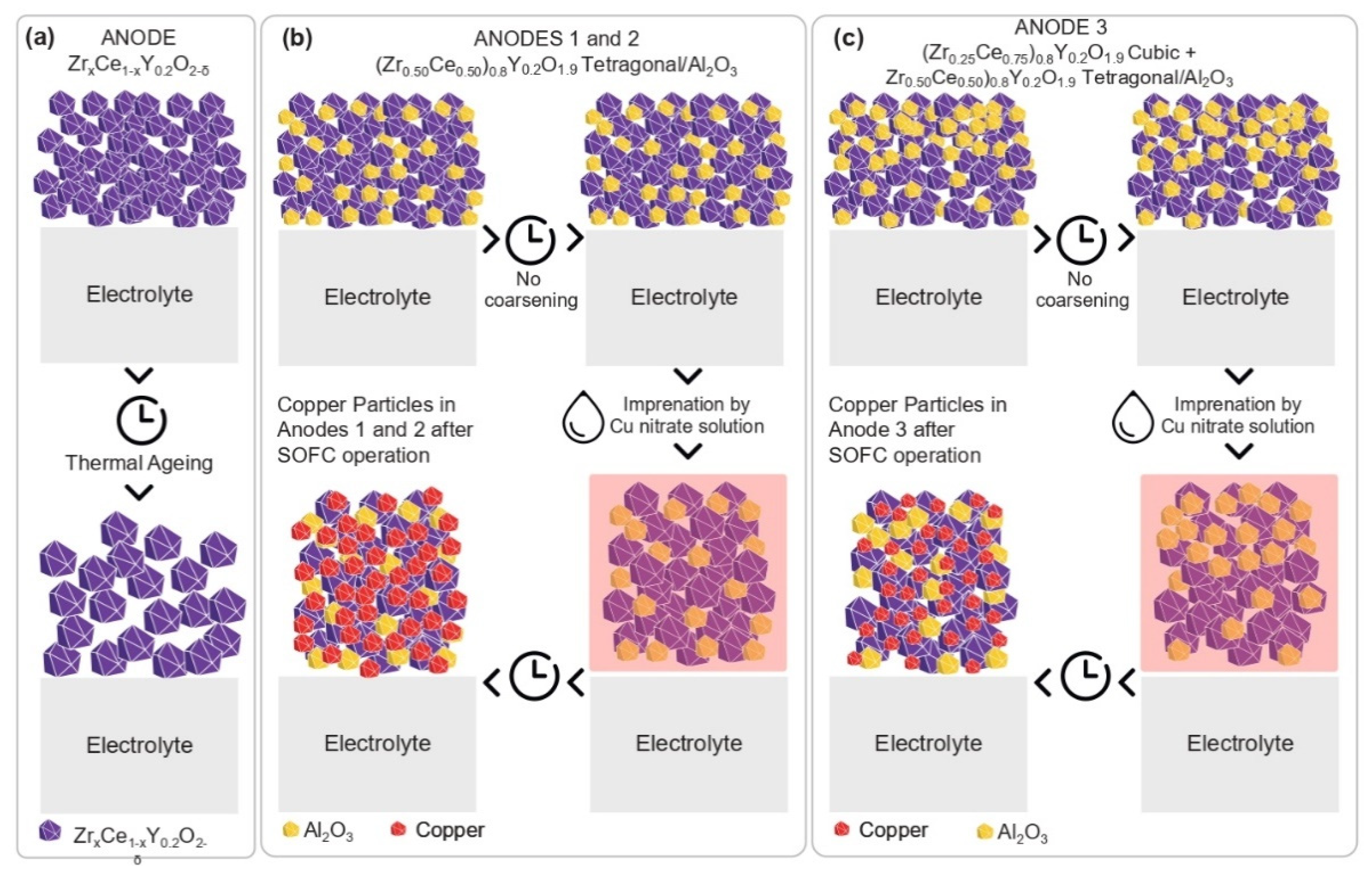
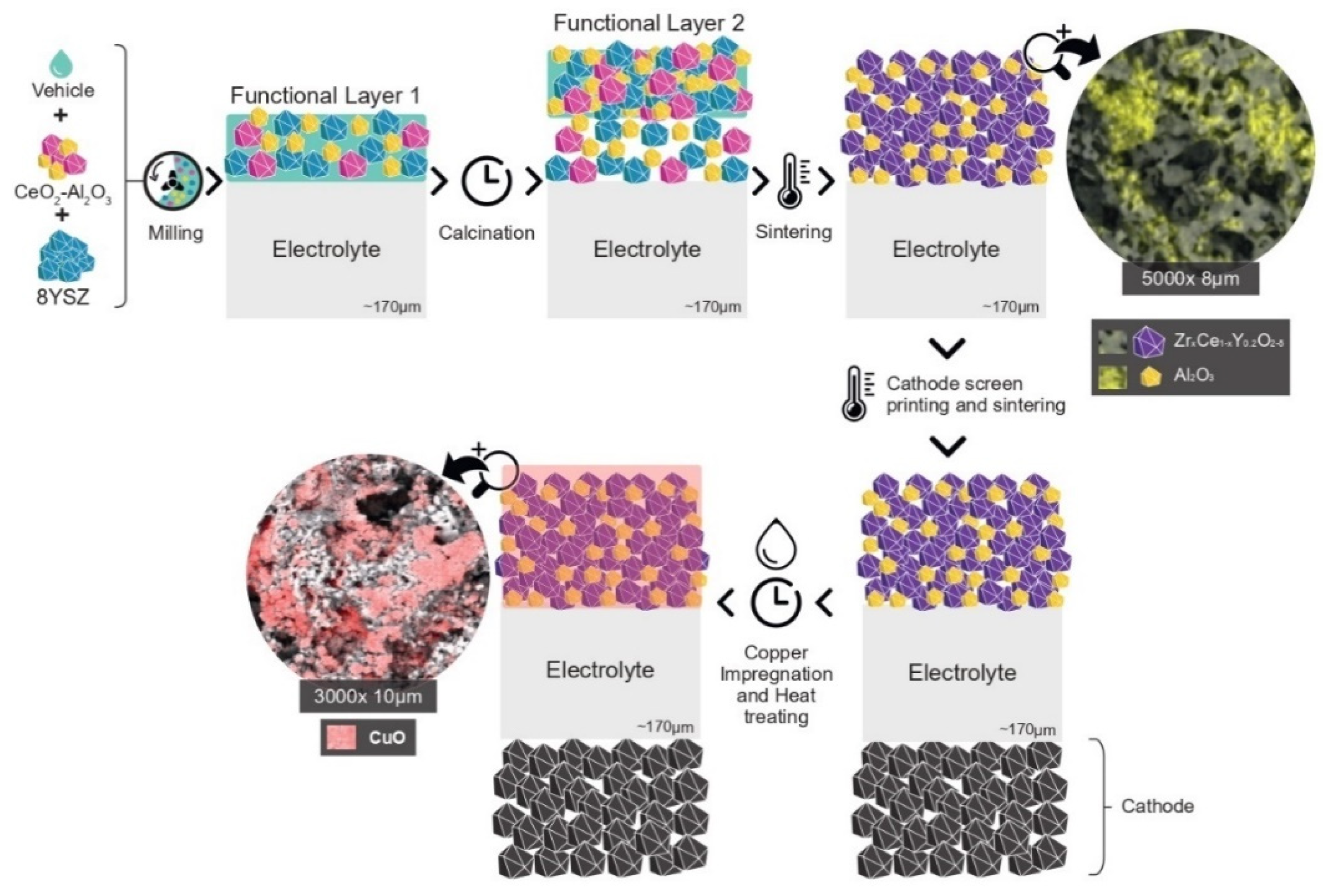
  • A new methodology was created for the synthesis of the electrocatalyst and preparation of the anodic electrode. A simple ceramic processing of the precursor materials CeO2-Al2O3 and 8YSZ, and sintering of the functional layers, favored the reaction between Ceria and 8YSZ in order to produce an anode composed of electrochemical active solid solutions such as (Zr0.25Ce0.75)0.8Y0.2O1.9, cubic, and (Zr0.50Ce0.50)0.8Y0.2O1.9, tetragonal, in addition to the Al2O3 phase. These solid solutions were homogeneously distributed in the anode’s microstructure, which exhibited an excellent OSC, while the presence of dispersed alumina improved the thermal, structural and mechanical stabilities;
  • The electrochemical activity of the solid solutions was directly related to their compositions and structure and favored a greater formation of defects in the surface and bulk sites, allowing the oxygen mobility to be improved. In this way, when operating in an SOFC-reducing atmosphere, the Ce4+ reacted with electrons, which were produced when an oxygen vacancy was formed, and it was reduced to Ce3+;
  • The crystallization of the Al2O3 phase in separate grains prevented its reaction with CeO2, avoiding the formation of the undesired perovskite CeAlO3 phase, since it induced a loss in the OSC. In the anode’s microstructure, the Al2O3 phase acted against thermal degradation, avoiding the coarsening of the solid solution and increasing the thermal, redox and mechanical stabilities of the solid solution;
  • The presence of alumina in the anode’s microstructure prevented the deactivation of the OSC properties, favoring the redox process of Ceria in the solid solution at high temperatures.

2. Results and Discussion

2.1. Anodes’ Structural Analysis

As described in Section 3, three anodes with different functional layers were prepared. Figure 2a presents X-ray diffractograms for each of the samples, before copper’s impregnation, along with their Rietveld fittings.
According to Figure 2a, only the tetragonal phase (Zr0.50Ce0.50)0.8Y0.2O1.9 was formed apart from Al2O3 in ANODE 1 and ANODE 2, while ANODE 3 was additionally composed of (Zr0.25Ce0.75)0.8Y0.2O1.9, cubic phase. In ANODES 1 and 2, the (Zr0.50Ce0.50)0.8Y0.2O1.9 phase percentage was over 80.0% mass, while that of the same phase reached only 29.7% mass in ANODE 3. This indicates that increasing the 8YSZ percentage in functional layer 2 favored the formation of (Zr0.50Ce0.50)0.8Y0.2O1.9 against (Zr0.25Ce0.75)0.8Y0.2O1.9 due to increasing the Zr4+ content in the mixture. The stoichiometries of the phases formed in every anode were within the ideal range of electrical conductivity according to an earlier study by Yokokawa et al. [27]. In that work, the authors related that the concentration of CeO1.5 is high in Zr1−xCexY0.2O2−δ compounds when 0.3 < x < 0.8. High concentrations of Ce3+ (CeO1.5) increase electronic conductivity in comparison with Ce4+ (CeO2) substitution, making the solid solution a better-mixed ionic–electronic conductor [27]. As observed in the diffractograms presented in Figure 2a, anodes 1, 2 and 3 presented high crystallinities of 99.31%, 99.72% and 95.19%, respectively. However, ANODE 3, in which the functional layer 2 was composed only of the CeO2-Al2O3 ceramic electrocatalyst powder, was slightly less crystalline. This can be attributed to alumina, due to its high concentration on the surface of this sample.
Table 1 presents the crystalline parameters for the anodes’ phases, as well as the interatomic distances and refinement coefficients. An analysis of these results indicated that the (Zr0.50Ce0.50)0.8Y0.2O1.9 cell parameters in ANODE 3 were slightly contracted compared to the same phase in ANODES 1 or 2. It can denote that the ANODE 3 phase diversity may be involved in a specific grain instead of separated ones, which favors the oxygen mobility in this sample since the diffusion through grain boundaries could limit it [28]. This fact may have produced a distortion in the fluorite unit cell, decreasing the oxygen ions binding energy and making them more susceptible to mobility. A more detailed anode phase’s analysis obtained from the interaction between Ceria and 8YSZ was performed with Raman spectroscopy, Figure 2b.
Figure 2b presents Raman spectra for ANODES 1, 2 and 3 before copper impregnation. As can be inferred from Figure 2b, the three spectra were very similar but differed by the magnitude of the band intensities and their format. It was observed that the 465 cm−1 band predicted for pure CeO2, whereby the Raman active mode of F2g symmetry allowed for CeO2 crystal lattice vibration [28,29], was shifted to a value around 483 cm−1 in all three cases. This shift to higher wavenumbers was due to the solid solution formation, which resulted from the crystal lattice shrinkage produced by Zr4+ substitutions [28,30,31,32]. This band became intense with the increasing CeO2 concentration in ANODE 3, which was attributed to the crystallization of the (Zr0.25Ce0.75)0.8Y0.2O1.9 cubic phase in addition to the (Zr0.50Ce0.50)0.8Y0.2O1.9 tetragonal one.
This may be accompanied by a decrease in the lattice parameter, resulting in shorter M (Ce or Zr)-O bond lengths, as observed in Table 1. The Raman spectra for every anode also presented weaker bands for wavelengths approximately equal to 132, 272, 334 and 588 cm−1. The variation in the relative intensity of these bands was very subtle and appeared to be an indication of the modification of the structure of the solid solution. These bands were sharper for ANODES 1 and 2 and could be related to the tetragonal (Zr0.50Ce0.50)0.8Y0.2O1.9 phase since it was more abundant in these samples (see Table 1). In addition to that, as pointed out by Eufinger J.-P. et al. [33], several modes that represent defects induced by oxygen vacancies in the solid solution have been observed between 100–450 cm−1 in the medium composition range (x = 0.25–0.75). This is consistent with the modes herein obtained for all three anodes. Furthermore, the substitution of zirconia into the Ceria lattice resulted in vacancies, which were also responsible for the occurrence of band broadening and the weak intensity range from 588.41 to 623.70 cm−1. This band was observed for the three anodes, which could suggest Ce3+ in the solid solutions lattice.
Observing these results presented in Table 1, it is possible to conclude that a lattice contraction and a reduction in the M-O average bond length, affected by the replacement of larger-sized Ce4+ cations by smaller-sized Zr4+ ones, might have occurred. However, this effect was slightly more pronounced for ANODE 3, which had two solid solution phases, (Zr0.25Ce0.75)0.8Y0.2O1 cubic and (Zr0.50Ce0.50)0.8Y0.2O1.9 tetragonal. This can suggest that for ANODES 1 and 2, with only the tetragonal phase, the expansion of the cell along the c axis appeared to compensate for the strain induced by the contraction of the lattice, which can maintain the amount of defects, while in the cubic structure, the stress induced favored the formations of the defects. In fact, it has been reported that the increase in the tetragonality of the solid solution can keep the number of defects almost constant due to the anisotropy of oxygen mobility [34]. This may occur since the displacement of the lattice oxygen from tetrahedral to the octahedral sites can generate Ce3+ sites in the lattice [28]. Zhang et al. [35] showed that Ce3+ with a larger ionic radius (0.1039 nm) than both Ce4+ and Zr4+ was formed in the solid solution in order to decrease the total lattice-strain energy that accrued due to the wide interval between the ionic radii of Ce4+ and Zr4+.
Thus, when the Zr concentration in the lattice becomes very large, the total OSC will eventually start to decrease due to the decreasing number of Ce redox couples.
In other words, it is necessary to maintain the redox equilibrium between Ce4+ and Ce3+. It is worth mentioning that the reduction in the M-O average bond length observed in these anodes can denote the presence of structural defects, indicating that the bulk of the materials were involved in the redox cycle.
Despite the Raman bands being attributed to Ceria-based solid solution phases, it was also possible to observe Raman bands at 1280.62, 1351.45, 1438.5 and 1535.33 cm−1 for all samples, which was attributed to the Al2O3 phase. The small difference in the intensity for these bands observed for ANODE 3 may represent the slightly lower crystallinity on the surface of this anode. This may have contributed to the lower oxygen storage and release capacities on the surface of this anode, as shown in Section 2.3.

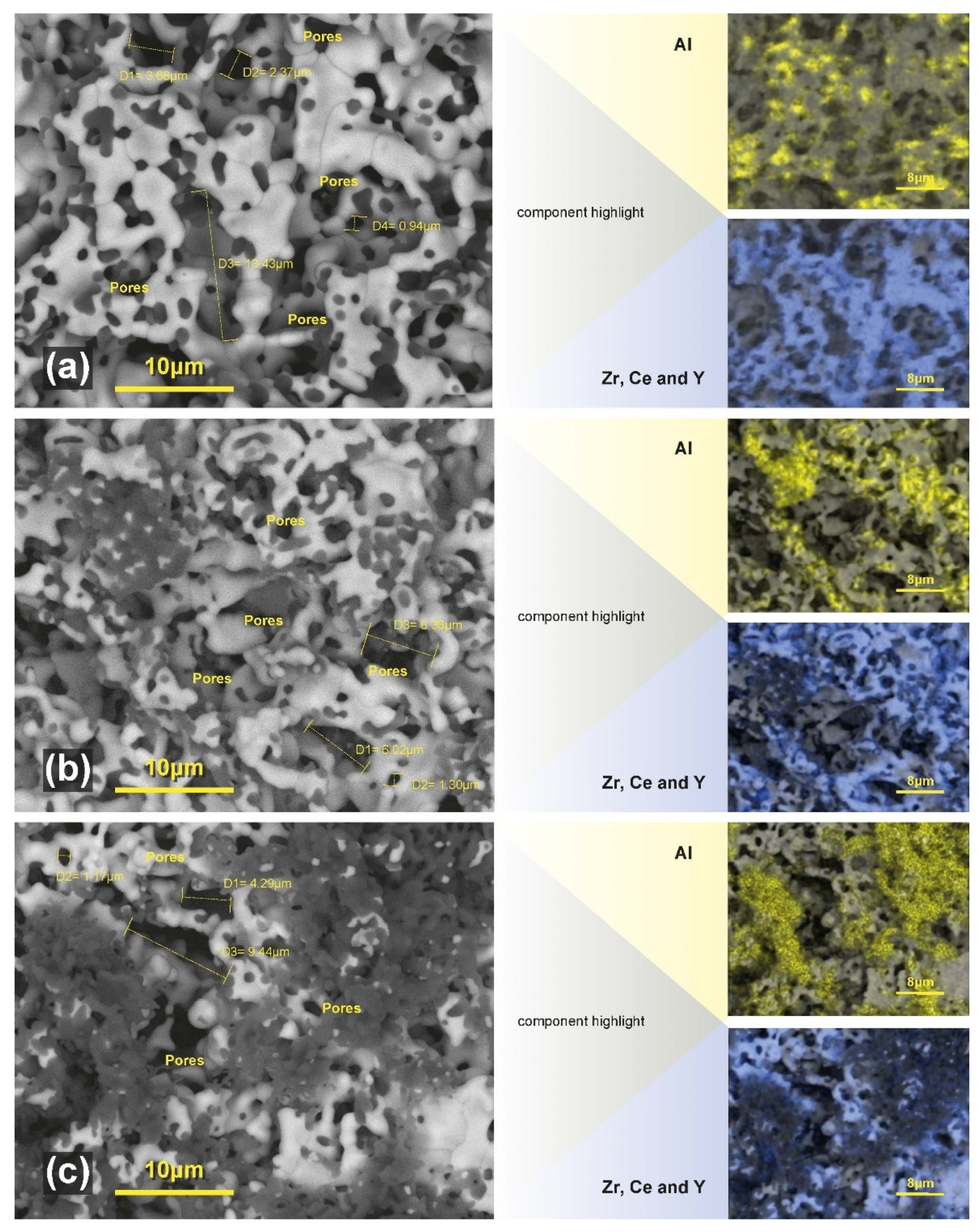
2.2. Morphology and Microstructure Analysis before Copper Impregnation

Taking into account that the anodes’ electrochemical properties are also related to their unique microstructures, a microstructural analysis was incorporated to the study in order to investigate this aspect. Figure 3 presents the cross sectional, Scanning Electron Microscopy (SEM), micrographs with Energy-Dispersive Spectroscopy (EDS), mapping of the anodes analyzed before copper impregnation.
The analysis showed homogenous and porous samples with small and large pores, mostly spherical and eventually interconnected to form elongated pores, which was attributed to the pyrolysis process produced by the cornstarch pore former. Based on the results from X-ray and Raman analyses and taking into account the EDS mapping in Figure 3, it can be inferred that the large grains corresponded to the ZrxCe1−xY0.2O2−δ solid solution, while the smaller ones were composed of Al2O3. Even though a quantitative estimation of the surface area of the anodes cannot be made, we can suggest from the visual observation of these microstructures that, according to the position of the Al2O3 phase in the samples (in yellow, on the right-hand side of Figure 3), it appears to create a barrier against solid solution self-diffusion, since most Al2O3 grains were visualized in the solid solution’s grain boundaries. It may be playing the role of the diffusion barrier, inhibiting the solid solution coarsening even after the high sintering temperature.
The experimental procedure used for the production and sintering of anodes significantly modified their structure, proving to be appropriate so that the reaction between CeO2 from the CeO2-Al2O3 and 8YSZ could take place, forming the solid solution. This favored the crystallization of the Al2O3 phase, preventing the reaction between CeO2 and Al2O3 from forming Cerium aluminate perovskite, CeAlO3. This means that the presence of highly dispersed 8YSZ within such a CeO2-Al2O3 electrocatalyst impeded the reaction of Ceria with alumina to produce CeAlO3. This result is relevant, because it is believed that the formation of CeAlO3 leads to a loss in the OSC below 900 °C, since the reduced Ce3+ species in CeAlO3 were not oxidized at temperatures below 500 °C [36,37]. This represented a concern, since our previous work [26] showed that within the synthesis process of the CeO2-AlO3 catalyst, Ceria can react with alumina to form CeAlO3 upon treatments carried out at lower temperatures. Kozlov et al. [38] reported that the tendency to form CeAlO3 is greatly suppressed for the supported CexZr1−xO2 [38] and only occurs for high-Zirconium-content preparations after undergoing severe thermal aging and reduction [38]. This is beneficial for SOFC anode operation because the presence of Cerium aluminate would hinder the anode oxygen ion storage capacity under the reducing atmosphere in the fuel chamber at high temperatures. When Zr4+, which has the coordination number 6, substitutes Ce4+, which has a coordination number equal to 8, structural defects are generated in the solid solution, increasing the oxygen ion mobility and the activity of the Ce4+/Ce3+ redox pair, which indicates that the phase formed is promising for applications as SOFC anodes.

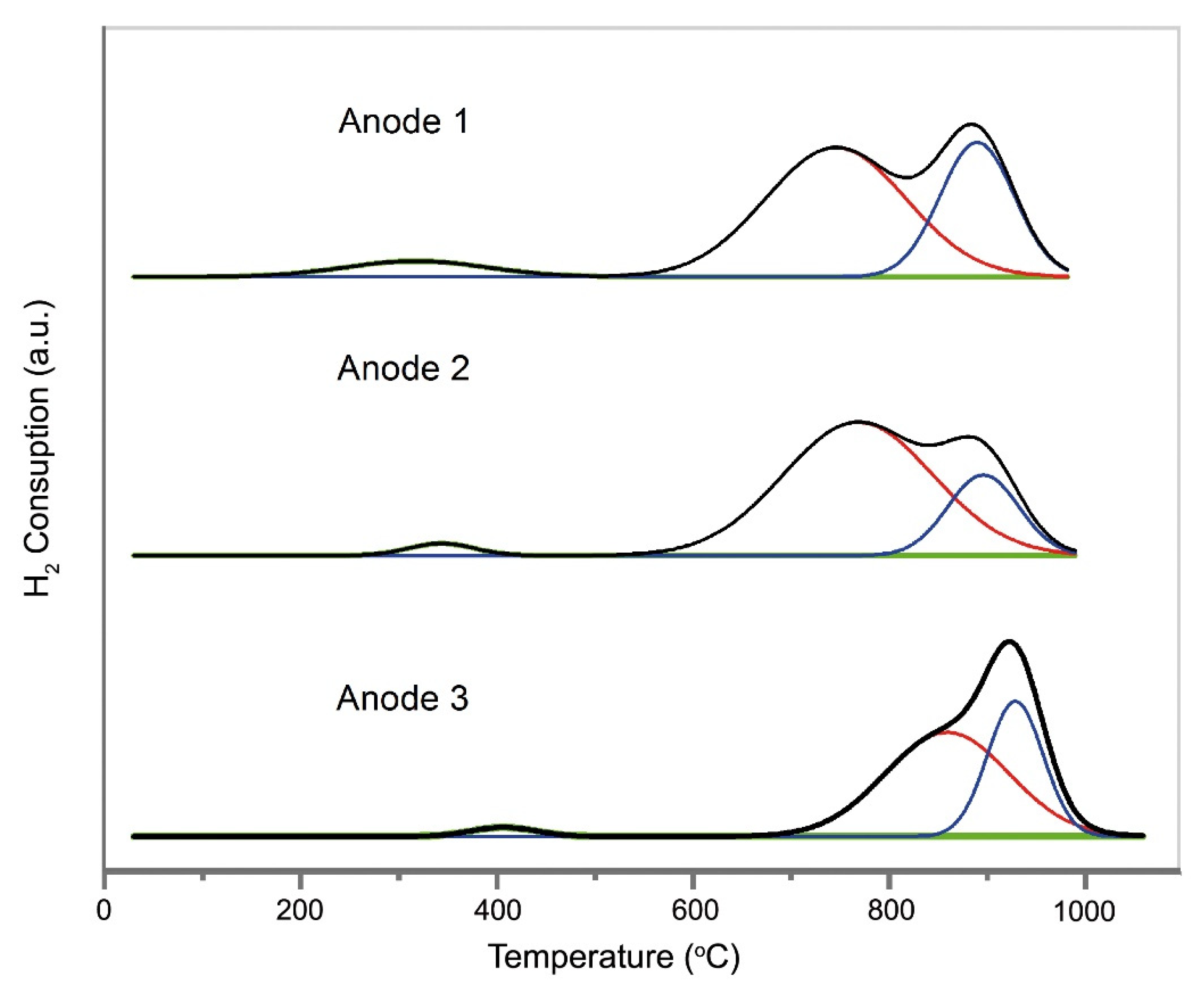
2.3. Reducibility and Oxygen Storage Capacity, OSC, Properties

In this section, the results relative to the temperature programmed reduction (TPR) and OSC of the anode materials sintered at 1500 °C for 3 h are reported. All three anode materials were subjected to two reduction and oxidation cycles before copper impregnation. The OSC was measured after each TPR experiment by reoxidizing the samples with pulses of O2 at 500 °C by temperature programmed oxidation (TPO) experiments. At 500 °C, the sample was fully reoxidized, and the O2 uptake can be taken as the measure of the amount of oxygen vacancies created upon reduction.
The TPR profiles of the anode materials are shown in Figure 4. For the three anodes, there were three broad reduction peaks, one in the low temperature range from 200 to 450 °C and two other ones in the high temperature range from 570 to 1000 °C, which can be ascribed to the reduction in Ce4+ and the surface and bulk of Ce4+, respectively [39,40]. It is known that the solid solution oxidation and reduction behavior depends on several factors, such as the pretreatment conditions, degree of sintering, specific surface area, thermal stability and the nature of the phases present [40]. Wei et al. [41], for instance, studied the OSC of Ce0.5Zr0.5O2 (without alumina)- and Ce0.5Zr0.5O2/Al2O3 (with an alumina composition ranging from 10 to 75 wt.%)-based catalysts. It was shown that when calcined at 600 °C, a low temperature, the samples with an Al2O3 concentrations between 10–50 wt.% presented less OSC than those without alumina. On the other hand, when the samples were calcined at 1000 °C, a high temperature, the OSC of the Ce0.5Zr0.5O2/Al2O3 samples was larger than that of the Ce0.5Zr0.5O2 without alumina. It has also been shown that, by increasing the alumina content from 10 to 75 wt.%, the OSC of the samples increases from 439.5 to 728.0 µmol g−1 and from 351.5 to 700.0 µmol g−1, respectively, for the heat-treated samples at 600 and 1000 °C. This implies that the specific surface area of the catalyst Ce0.5Zr0.5O2/Al2O3 becomes larger and the proportion of usable Cerium also increases correspondingly by increasing the Al2O3 content [41]. It can be said that by comparing the two mixed oxides, those containing alumina in their composition present a better thermal stability of OSC at high temperatures.
Thus, for the purpose of the corroboration and validation of the reactivity of the anodes developed in the present work, Table 2 presents the TPR and OSC relative results for the three anode materials, along with some data obtained and reported in the literature by Wei et al. [41]. With this objective, only the solid solutions with alumina compositions equal to 10 and 25 wt.%, which most closely matched the phase composition of Al2O3 obtained for the three anodes in the present paper, as seen in Table 1, are reported here. In addition, only the data published by Wei et al. [41] for the highest calcination temperature, which is 1000 °C, was used for comparison. It is worth mentioning that this comparison is presented here in the sense of showing the efficiency of the developed material; however, the testing conditions and composition of each material should be considered.
Comparing, for example, the results obtained for ANODE 3, which had approximately 21.1% of Al2O3 in its composition, with those obtained by Wei et al. [41] for the Ce0.5Zr0.5O2 sample without alumina, an increase of 96.7 µmolg−1 was observed for the anode material. This indicates that the Al2O3 present in the anode composition can act as a thermal stabilizer, preventing the grain growth of the solid solution and thus favoring its activity during SOFC operation. In relation to the solid solution of Ce0.5Zr0.5O2 without alumina, both Ce0.5Zr0.5O2/Al2O3 composites from the literature [41] and those of the present work, ZrxCe1−xY0.2O2−δ-Al2O3, showed a higher OSC.
The specific surface areas of the anode materials are not presented here since the evaluation of their reduction and oxidation behavior was performed following the real conditions of an SOFC anode, that is, the measurements were obtained on “pellet” samples sintered at 1500 °C. This one again indicates the reactivity of the produced anodes and their stability regarding the thermal effect, since even with highly sintered samples, they present an OSC favorable to the application where the CeO2 is usable for the redox process. However, as shown in Figure 4 and Table 2, the total O2 uptake after reduction up to 1000 °C was similar for the three anode materials, indicating that a similar amount of oxygen vacancies is created in these three samples upon reduction. However, the amount of hydrogen consumed by ANODE 3’s surface was the lowest. This may indicate that ANODE 3’s oxygen storage and release capacities are greater in the bulk than on the surface. As stated above for the Raman analyses, the bulk of the anodes were involved in the reduction–oxidation cycles due to the presence of structural defects. It is noticeable that the phases present in each anode influenced the temperature of occurrence of their reduction peak. ANODES 1 and 2 possessed a greater concentration of the (Zr0.50Ce0.50)0.8Y0.2O1.9 tetragonal phase (Table 1) and also similar temperature peak occurrences and areas. Conversely, ANODE 3 presented a small displacement of its reduction peaks to higher temperatures, which may have been related to the predominant presence of the (Zr0.25Ce0.75)0.8Y0.2O1.9 cubic phase, with a higher concentration of CeO2. The Ce4+/Ce3+ surface and bulk reduction peaks of ANODES 1 and 2 migrated toward lower temperatures, demonstrating that higher Zr concentrations can promote Ce4+/Ce3+ reductions with lower activation energies. Thus, it was considered that ANODE 3, with a higher CeO2 concentration, stored and released oxygen more slowly than the Zirconia-rich ANODES 1 and 2. This is in agreement with what was reported by Balducci et al. [42], who demonstrated that a Zirconia insertion can promote the reduction in bulk Ce4+ with a lower activation energy. It may mean that while materials with higher Cerium levels can store and release more oxygen, they do so more slowly than Zirconia-rich materials, which release smaller oxygen amounts but do so more quickly [43]. Although the total amount of hydrogen consumed and oxygen absorbed by the ANODE 3 material was the lowest, it was the one that presented the highest electrochemical performance, as is demonstrated in Section 2.5. It can indicate that the smallest amount of hydrogen consumed by this multifunctional anode is only on the surface, which may be due to the small amount of the amorphous phase presented on the surface of this sample. It suggests that a further reduction of bulk Ce4+ will have a greater influence on its application as a SOFC anode. When the SOFC anode is under a reducing atmosphere at high temperatures, higher fuel consumption will result from the greater availability of free oxygen in the bulk lattice. Under electric load, this effect can be increased, and thus oxygen from the bulk lattice will migrate to the surface. Consequently, more oxygen vacancies will be formed and will diffuse in the opposite direction, spreading themselves inside the crystal. It was shown that the incorporation of ZrO2 into a solid solution with CeO2 strongly promotes the bulk reduction of an anode’s solid solutions with both phases in comparison to a solid solution with only the tetragonal phase, which confirms the structural dependence of both reduction and oxidation processes. This may favor the diffusion of oxygen ions from the SOFC electrolyte and thereby increase the fuel cell performance since oxygen ions from the electrolyte occupy the vacancies, which thereby balances the charge of the solid solution. In addition to that, the presence of higher fractions of the Al2O3 phase in ANODE 3 might have positively influenced the SOFC performance, since it increased the thermal resistance of the material and minimized particle coarsening at high SOFC operating temperatures. The confirmation of this stability was also presented in the electrochemical performance tests, in which the SOFC were operated at temperatures up to 950 °C for approximately 200 h without performance degradation.

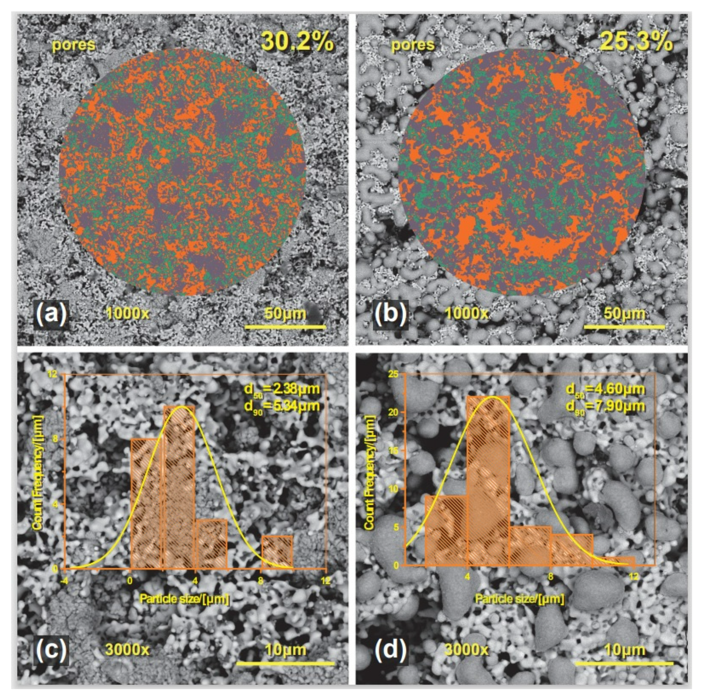
2.4. Morphology and Microstructure Analysis after Copper Impregnation

In order to increase the carbon deposition resistance as well as the electronic conductivity of the anode, copper was introduced in the anode as described in Section 3. In the anode structure, Cu acts as an electrical conductor inert to carbon deposition while the solid solution ZrxCe1−xY0.2O2−δ enhances the performance the electrocatalyst for fuel oxidation and also assists in charge transfer at the interface. Figure 5 shows the micrographs obtained via SEM with the EDS mapping of ANODE 3 (it is shown here only for ANODE 3, since the microstructures of the three anodes did not show significant differences).
On the left-hand side of Figure 5, it is possible to observe the microstructures of (a) the surface and (b) the cross section obtained prior to the SOFC’s operation. While on the right-hand side of Figure 5, the microstructures of (c) the surface and (d) the cross section after the SOFC’s operation under hydrogen and ethanol atmospheres, subsequently, may be observed. It is possible to observe from the micrographs that no carbon species were deposited either on the surface or in the anodes’ volume after the cells’ operation under an ethanol atmosphere. The carbon deposition resistance of this anode was studied in our previous work [44], where it was shown that there was no evidence of carbon formation for the anode operated at 750 °C, and it even retained its copper-like color. However, very little carbon deposition was observed for the anode operated at 950 °C, where it was shown that a thin carbon film was deposited on the anode’s surface. In this case, the carbon film is easily removed by scratching the anode’s surface to show the same appearance as shown by the anode operated at 750 °C, without compromising the microstructure of the anode. As shown in the micrographs after the fuel cells operation, many rounded Cu agglomerations could be found around the pores of the anodes, which was not surprising considering the high sintering susceptibility of Cu at high temperatures. Li et al. [45] reported a similar copper particle growth when producing a Cu-YSZ anode. According to them, the electrical conductivity analysis of this anode decreased drastically in the first 4 h under a hydrogen atmosphere at 700 °C. It was concluded that the Cu conductivity path was formed via connections between isolated islands through weak necks when subjected to high temperatures; some weak necks started to break up, leading to a drastic electrical conductivity reduction [45]. However, this was not consistent with the performances of the fuel cells herein presented since they were operated for about 200 h without observable degradation of the electrical conductivity.
One possible explanation for understanding the present results is shown in Figure 6, wherein the anodes’ porosity was analyzed, as well as the copper particle size. The micrographs in Figure 6a,b were analyzed using the image analysis tool Metallographica to assess the porosity levels of the anodes before and after the SOFC operation. In Figure 6a, the anode surface is seen in magnification (1000×) and the porosity, classified as orange, is estimated to be 30.2%, whereas in Figure 6b, the porosity level measured at the anode surface is 25.3%. The infiltrated copper oxide particle presented a size range from 1 to 5.34 µm that was poorly distributed in aggregates, forming isolated islands, as shown in Figure 6c, which may suggest that the interfacial energy between CuO and ZrxCe1−xY0.2O2−δ-Al2O3 is relatively high, resulting in particle agglomeration during manufacturing processes. These agglomerates increased in size (a range from 1–7.9 µm), Figure 6d, after their reduction to metallic copper, which occurred during the SOFC operation at high temperatures.
However, the anode porosity level after the fuel cell operation was slightly lower than the desirable one reported in the literature. According to Tiwari et al. [46], an anode porosity of 30–40% provides better percolation for the gas phase into the reaction sites. However, as we can see in Figure 5d, the cell’s cross section morphology suggests that the anode porosity was well kept throughout the electrodes’ bulk. It was then concluded that despite copper’s low thermal stability at high temperatures, the copper particle growth was not enough to compromise the porosity of the anode and prevent its operation. Furthermore, as will be seen from the electrochemical performance results in Section 2.5, the cells’ V-I curves showed that the performance increased appreciably with temperature, showing once again that copper coarsening was not enough to cause high resistance to the SOFC operation.
Therefore, it is reasonable to suggest that the Cu conductive path is also formed by weak connections between the separate islands, since it is possible to observe copper agglomerates throughout the anodes. Thus, considering that the porosity has not been highly compromised by copper coarsening in the anodes’ microstructures and the poor contact between the copper particles, we can infer that the conductive paths in the anode microstructure were mainly formed by the solid solution in its reduced state. This was evident due to the better distribution of the solid solution phases in the anodes’ microstructure from the surface to the triple phase boundaries (TPB) regions. This occurred because during the fuel cell operation under a hydrogen or ethanol atmosphere, the CeO2 from the solid solution could be reduced and form large oxygen vacancies, further resulting in the significant enhancement of electronic conduction in addition to oxygen ion conductivity.
It is worth mentioning that a better dispersion of copper must be studied in order to really prove its contribution throughout the anode’s microstructure. By analyzing the micrographs of the anodes after operation, it is not possible to observe any evidence of cracks either in the microstructure or at the interfaces, as well as the grains’ coarsening of the solid solution in relation to the samples before the SOFC operation, Figure 3. The absence of mechanical deformations after the SOFC operation for 200 h seems to be correlated with the Al2O3 phase present in the anodes’ microstructures.

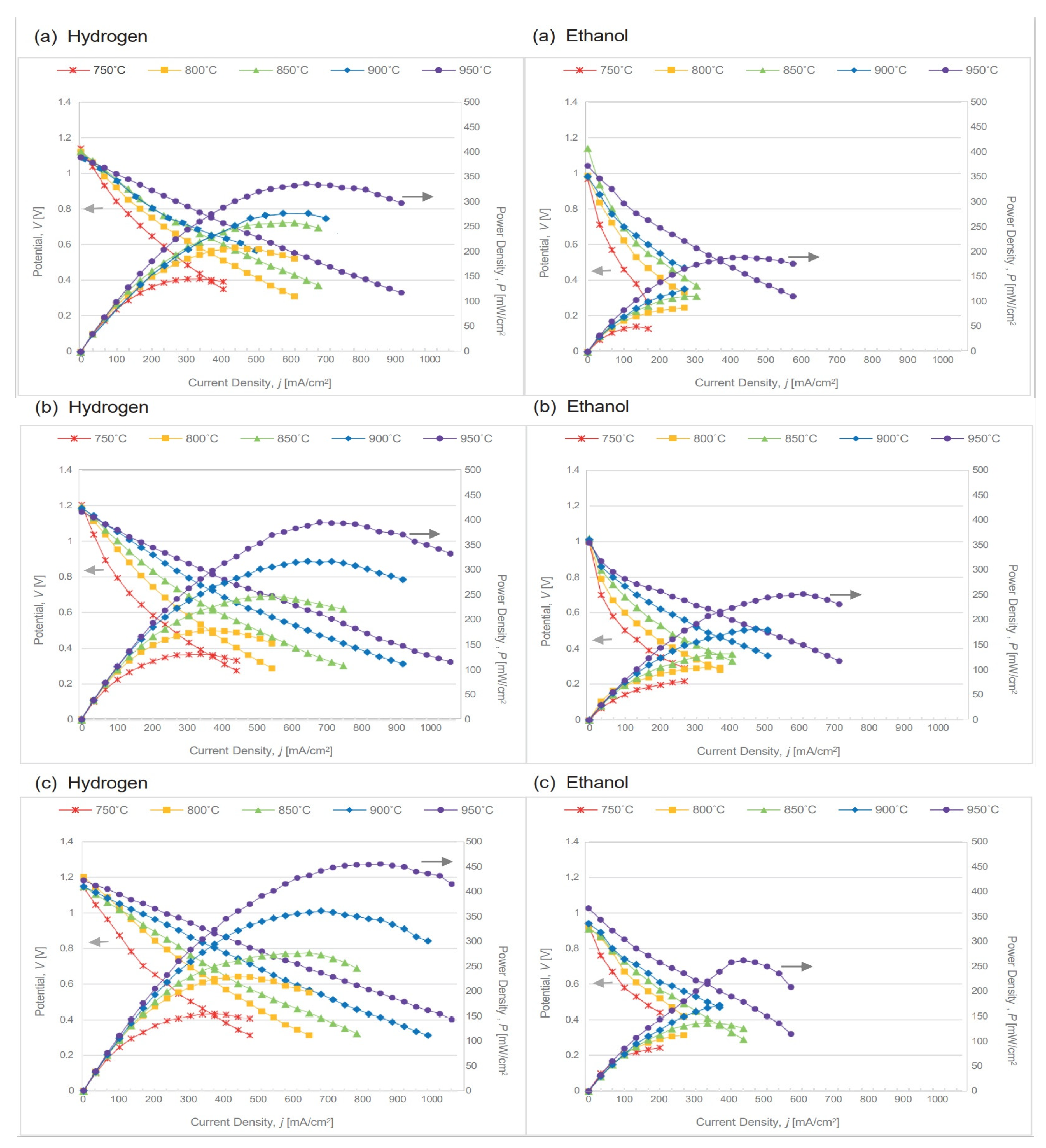
2.5. SOFC’s Electrochemical Performance

Based on the principle that the carrier electrons dominate the electronic conductivity in solid solutions, their concentration is increased by the reduction of tetravalent Cerium ions to trivalent ones [27]. In this sense, the concentration of Ce3+ gives information related to the electronic concentration, because the electric properties are composition dependent. Yokokawa et al. [27] demonstrated that the electron conductivity increases with the addition of CeO2 in the ZrxCe1−xY0.2O2−δ solid solutions and also that the surface exchange reaction rate increases. Dong et al. [47] demonstrated that due to the increase in the rate of oxygen vacancy migration, the electrical conductivity increases with an increasing temperature. This was confirmed in this work through the electrochemical performance of ANODES 1, 2 and 3. In this case, the bulk oxygen vacancies, which were created by the reduction of the solid solution, directly participated in the SOFC electrochemical process. Figure 7 presents the potential and power density versus current density curves for the SOFC composed of the anodes herein studied with the different stoichiometries of the solid solution ZrxCe1−xY0.2O2−δ. It is worth mentioning that, as the three SOFC were composed of the same amount of copper (see Section 3), their different electrochemical performance was directly related to the solid solution phase. It was clearly observed that the electrochemical performance of the SOFC increased with an increasing temperature, showing once again that the coarsening of the copper particles did not directly influence this performance. This result also confirms that the thermal stability of the solid solution was favored by the alumina phase, otherwise the best performance would be at lower temperatures where this effect would be reduced. ANODE 2, with a greater percentage of 8YSZ in the functional layer 1 with respect to ANODE 1, presented a slightly higher electrochemical performance, which may have been related to a better anode/electrolyte interface contact, favoring ionic diffusion. Preparing the functional layer 2 in ANODE 3 with a 100% Ceria-alumina precursor against 50% in ANODES 1 and 2 led to a higher concentration of (Zr0.25Ce0.75)0.8Y0.2O1.9, cubic phase, and resulted in a higher electrochemical performance. This result shows compliance with the arguments presented about the solid solution ability to reduce and store oxygen, since for the three anodes studied when in operation under a reducing atmosphere, the Ce4+ from the solid solution will be reduced to Ce3+ since the insertion of Zirconia in the Cerium lattice induces the formation of defective sites in the surface and bulk, producing electrons. For ANODE 3, which also has a cubic phase, these defects are more pronounced in the bulk. It favors its performance in the SOFC operation atmosphere since the mobility of oxygen in the bulk is strongly appreciative for allowing the entire area of the anode material to participate in the redox process.
As expected, better results were obtained for SOFC operating with direct hydrogen, reaching a maximum power density of 455 mW/cm2, compared to 261 mW/cm2 obtained for the direct utilization of ethanol at 950 °C in the SOFC possessing ANODE 3. It can be related to the heavier ethanol molecules, the presence of the products obtained from the fuel’s thermal and electrochemical decomposition and the partial oxidation of the fuel, for which the resultant molecules induce slower fuel gas diffusion, increasing the concentration polarization. As already mentioned, the electrochemical performance results presented for all the temperatures were obtained after 200 h of operation. To be able to evaluate and compare the performance during this time, the SOFC were kept at a constant potential of 0.5 V. The data were monitored and collected approximately every 48 h until reaching the specified operation time of 200 h. During monitoring, for each temperature, there was no significant change in the performance and a power density variation of approximately 3.0 mW/cm2 was observed, as shown in Figure 8a,b (it is shown here only for ANODE 2, since the results of the three anodes did not show significant differences). However, as the temperature increased, the electrochemical performance also increased; this occurred for the SOFC operated with hydrogen as well as for those operated with ethanol. These data once again confirm the thermal stability of the studied anodes. It is worth emphasizing that the magnitudes of the power densities measured and presented in Figure 7 and Figure 8a,b were strongly dependent on the fact that electrolyte-supported SOFC cells were used with a rather thick electrolyte. This means that with both hydrogen or ethanol as fuels, these power densities would unveil magnitudes of a much higher value if the anode-supported SOFC cells were to be utilized, bearing rather thinner electrolytes.
A significant portion of the ethanol that feeds the SOFC anode is thermally decomposed in its path in the anode channel. It depends on the pressure, temperature, residence time and feed gas composition. According to theoretical and experimental studies, in SOFC anode conditions at temperatures > 750 °C, most ethanol is thermally decomposed [2,19,44,48,49]. As a result, the electrochemical reactions that occur in the reactional triple region in the presence of ethanol, hydrogen, ethylene, carbon monoxide and methane among other products [2,19,44,48,49,50,51] would certainly influence the thermodynamics of Nernst’s potential. These products are surely less efficient for electron release to the main current flux than using hydrogen that is readily oxidized by the SOFC anode. Therefore, the electrochemical oxidation of ethanol and its products can be described in terms of their elementary steps. Ethanol decomposition inside a solid oxide fuel cell at high temperatures is a subject that was also presented in our previous paper [44,48]. However, to complement this study, effluents from the electrochemical reactions of SOFC directly fed with pure ethanol at 750, 850 and 950 °C were then analyzed at the maximum power density through gas chromatography, as shown in Figure 8c. It was observed that at all the SOFC operating temperatures, ethanol was completely decomposed into CH4, H2, C2H4, C2H6, CO and CO2. The presence of water was observed in the system, but it was not possible to be quantified. With the increase in the operating temperature and power density of the SOFC, there was an increase in the concentration of CH4, CO2 and CO. Although a slight reduction in the concentration of C2H4 and C2H6 was observed, significant amounts of these hydrocarbons remained until the highest operating temperature of 950 °C.
A deeper interpretation of the results herein obtained was achieved by analyzing the redox behavior during the SOFC operation and explaining it through a schematic representation shown in Figure 9a,b, and the theoretical physical–chemical mechanism is as follows.
The thermal decomposition of ethanol is most likely to produce high concentrations of hydrogen and CO [2,19,49] that become the main products consumed by the electrochemical reactions at the SOFC anode. An increased concentration of hydrogen and carbon monoxide will facilitate electrochemical oxidation. For instance, the hydrogen chemisorbed ( H ) in such a catalytic free site ( ) of the anode reacts with oxygen ions to form water and electrons, as shown by Equations (1)–(3):
H 2 + 2 = 2 H  
2 H + O 2 = H 2 O + 2   + 2 e
H 2 + O 2 = H 2 O + 2 e ,   Δ H o = 242   kJ · mol 1
Similarly, the oxidation reactions of carbon monoxide at the anode–electrolyte triple phase boundaries are given by Equations (4)–(6), through which the CO chemisorbed ( C O ) in such a catalytic free site ( ) of the anode reacts with oxygen ions (O−2) to form CO2 and electrons:
C O + = C O
C O + O 2 = C O 2 + 2 e
C O + O 2 = C O 2 + 2 e ,                           Δ H o = 283   kJ · mol 1
This process takes place on the solid solution of ZrxCe1−xY0.2O2−δ that is efficient for oxygen storage and release. Figure 9b presents a schematic of this solid solution reaction as a reversible process. To ensure the charge neutrality in the solid solution lattice when Ce4+ is reduced to Ce3+ in the SOFC atmosphere, oxygen vacancies ( V o ¨ ) are formed [52]. In the anode solid solution, this reversible process on the Ceria lattice site is represented by Equation (7) [52]:
2 C e + 4 + O 2 = 2 C e + 3 + V o ¨ + 1 2 O 2
Thus, when an oxygen vacancy is formed, two free electrons are produced; once they are at the lattice site, these electrons will react with two Ce4+ ions that will be reduced to Ce3+ ions [52]. In the anode operation condition, oxygen ions from the electrolyte occupy the vacancies, balancing the charge of the solid solution. This is a very important way to improve the mixed ionic–electronic properties of the solid solution considering that the SOFC operation atmosphere leads to CeO2 chemical defects in the lattice bulk and at its surface. This process can be considered as a doping procedure due to the substitution of Ce4+ by Ce3+.
In this condition, hydrogen and carbon monoxide react with oxygen ions, forming steam and carbon dioxide and leaving four electrons behind. If ethanol only eventually pyrolyzes partially, a certain amount of pure ethanol will be directly oxidized at the anode, Equation (8):
C 2 H 5 O H + 6 O 2 = 2 C O 2 + 3 H 2 O + 12 e ,     Δ H o = 1.367   kJ · mol 1
The presence of H2O and CO2 at the anode compartment may also facilitate fuel reforming paths, such as Equation (9):
C 2 H 5 O H + H 2 O = 2 C O + 4 H 2 ,     Δ H o = 343   kJ · mol 1
In this case, the water gas shift (WGS) reaction has to be considered, Equation (10), to result in more CO2 and H2; carbon formation and reactions for its removal may also take place [53]:
C O + H 2 O = H 2 + C O 2 ,     Δ H o = 283 + 242 = 41   kJ · mol 1
In addition to these reactions, methane, activated by chemisorption on the anode surface, is also oxidized, Equation (11):
C H 4 + 4 O 2 = 2 H 2 O + C O 2 + 8 e ,     Δ H o = 802   kJ · mol 1
The occurrence of ethylene and ethane can also take place at the SOFC anode, as shown in Equations (12) and (13), considering the total oxidation, as was discussed in our previous work [48]:
C 2 H 4 + 6 O 2 = 2 C O 2 + 2 H 2 O + 12 e
C 2 H 6 + 7 / 2 O 2 = 2 C O 2 + 3 H 2 O + 7 e

3. Materials and Methods

3.1. Anode Concept

The anode concept is schematically shown in Figure 10. As indicated in Figure 10a, the base anode was composed solely of the solid solution ZrxCe1−xY0.2O2−δ, in which case particle growth may have occurred due to thermal degradation when subjected to high temperatures, thus reducing its specific area. Accordingly, in order to increase the SOFC’s efficiency, we hindered the anode deactivation by the particles’ coarsening, and three new anode compositions were developed with the addition of the more thermally stable Al2O3 phase, since alumina is heat resistant. These arrangements yielded anodes with different compositions of solid solution phases. ANODES 1 and 2 presented the tetragonal phase (Zr0.50Ce0.50)0.8Y0.2O1.9 apart from Al2O3, while ANODE 3 was additionally composed of (Zr0.25Ce0.75)0.8Y0.2O1.9, cubic phase, as shown schematically in Figure 10b,c. Due to its features, alumina was also selected as a copper particle size growth inhibitor during SOFC operation in the present anode conception. Figure 10b,c present a slightly higher coarsening inhibition effect for ANODE 3, while Figure 10c presents a higher concentration of alumina in its composition.
The first attempt to achieve the solid solution thermal stabilization was the production of the nanostructured electrocatalyst CeO2-Al2O3 [26]. However, as has been described in our previous work [26], an SOFC anode made with such a material presents a very particular redox behavior. The original anode phases CeO2 and Al2O3 under an oxidizing atmosphere at a low temperature were kept as separated phases. When they were submitted to a reducing environment at the SOFC high operating temperatures, they reacted and were reduced to the CeAlO3 perovskite. This phase transformation mechanism is reversible, since the CeAlO3 perovskite is the origin of the same original phases, CeO2 and Al2O3, when taken to the low temperature oxidizing atmosphere condition. It looks interesting and is similar to what happens with the nickel oxide cermet that reduces to metallic nickel at high temperatures under a reducing atmosphere to present its desired electrocatalytic behavior, and it oxidizes back to nickel oxide at low temperatures under an oxidizing atmosphere, reproducing the nickel oxide yttria stabilized zirconia, YSZ, cermet that originally constituted the SOFC anodes. However, as CeAlO3 perovskite, CeO2 is no longer present and able to perform its redox reaction, Ce4+ ↔ Ce3+, which impairs the charge transfer for the necessary SOFC anode electrochemical reaction, which eventually inactivates the SOFC anode. The challenge faced involves avoiding the occurrence of the CeO2-Al2O3 reaction at high temperatures under the reducing atmosphere of the SOFC operation condition to produce the CeAlO3 perovskite. A solution was achieved by previously mixing the nanostructured electrocatalyst CeO2-Al2O3 with the electrolyte material, 8YSZ, and ceramic processing such a powder to produce ceramic suspensions that were sintered to the SOFC anode. When the CeO2-Al2O3-8YSZ mixture is sintered, the solid solution ZrxCe1−xY0.2O2−δ is formed, and alumina crystallizes separately and acts as a solid solution stabilizer, therefore avoiding the formation of the CeAlO3 perovskite. The CeO2-Al2O3-8YSZ mixture presents reversible redox reactions with the formation of the solid solution ZrxCe1−xY0.2O2−δ and dispersed Al2O3. Details of this process are shown in Section 3.2 an in a patent of ours [54].
As a matter of fact, the reaction between CeO2 and 8YSZ is more facilitated considering, for example, the smaller cation radius of Al3+ (0.059 nm) compared to those of Zr4+ (0.084 nm) and Ce4+ (0.097 nm). These alumina properties have been previously reported [55,56], where the diffusion barrier concept was demonstrated through introducing Al2O3 into the CeO2-ZrO2 solid solution on a nanometer scale. This is certainly not our case, since the anodes are sintered at 1500 °C. Our goal is to avoid mechanical deformations during the redox process and the consequent delamination of the electrodes due to solid solution coarsening and structural changes that seem to be correlated with the intrinsic expansion of the solid solution lattice when Ce4+, which has a smaller radius, is reduced to Ce3+, with a greater ionic radius (0.1039 nm). Thus, in this new anode concept, the solid solution ZrxCe1−xY0.2O2−δ contributes to the fuel oxidation and to the mixed conduction; additionally, copper also acts as an electrical conductor inert to carbon deposition, and Al2O3 contributes to prevent the coarsening and densification of the solid solution’s particles during sintering and the anodes operation, as well as cracks in the anodes and/or anode/electrolyte interfaces during redox cycles. This is extremely important to develop a robust anode with a long lifetime, keeping the desired electrochemical activity.

3.2. Cells Fabrication

In order to study the functionality of anodes based on Cu-(ZrxCe1−xY0.2O2−δ-Al2O3) composition, three single SOFC types were produced, in which each anode had two different functional layers, as shown in Table 3. The experimental procedure used for the production of single cells is shown schematically in Figure 11. These functional layers’ compositions were designed in order to allow for the solid solution formation, ZrxCe1−xY0.2O2−δ, promoting the mixing of the precursors CeO2-AlO3 and 8YSZ catalyst powders during ceramic processing and their interdiffusion during the anodes’ sintering. For this development, three ceramic suspensions with different compositions were obtained from the following precursors: 8YSZ catalyst powder from TOSOH Corporation; nanostructures ceramic electrocatalyst powder, CeO2-Al2O3, synthesized through the amorphous citrates’ method [26]; pore former, cornstarch, from Sigma-Aldrich; and a terpineol-based vehicle from Fuel cell Materials.
Each composition, shown in Table 3, was processed in a planetary ball mill for 6 h at 200 rpm. After the ceramic suspensions production, the anodes were screen printed over an 8YSZ button-type electrolyte support with 20 mm in diameter and an approximate thickness of 170 µm.
Initially, the ceramic suspension of functional layer 1 (8YSZ-richer layer) was deposited and heat treated at 1000 °C for one hour. Subsequently, the ceramic suspension of functional layer 2 (CeO2-Al2O3-rich layer) was deposited and the ensemble was sintered at 1500 °C for three hours. After that, over the other electrolyte side, the ceramic suspension of the lanthanum Strontium-doped Manganite, La0.8Sr0.2MnO3, (LSM) cathode from Fuel cell Materials was screen printed and sintered at 1100 °C for two hours. The active area of both electrodes was 0.5 cm2 with a thickness of approximately 50 µm. An aqueous solution of (Cu (NO3)2.3H2O) was produced and cautiously dropped onto the anodes porous surfaces in order to attain 20 wt.% of Cu inside the Cu-(ZrxCe1−xY0.2O2−δ-Al2O3) system. This concentration was obtained after seven impregnation steps. After each impregnation, the anodes were dried at 450 °C for 30 min. Copper oxide was reduced to metallic copper during the SOFC activation for two hours under a hydrogen atmosphere. The production delivered 3 cells named ANODE 1, ANODE 2 and ANODE 3. Platinum wires and mesh were inserted on the anode side, and gold wires and mesh were added to the cathode side to serve as current collectors.

3.3. Characterization Techniques and Performance Test

The analysis of the possible relations between anode precursor oxides is highly interesting, since their real properties arise from these interactions. Thus, X-ray diffraction and Raman spectroscopy were performed on the multifunctional anodes before copper impregnation in order to obtain information about the actual phases and structural analyses of the anodes constituents’ elements. The multifunctional anodes were characterized by X-ray diffraction (XRD) using an XRD-6000 diffractometer, from Shimadzu Corporation, Tokyo, Japan, with a Cu Kα = 0.1506 nm radiation source, varying 2θ from 10° to 90°, so that peaks corresponding to the solid solution, ZrxCe1−xY0.2O2−δ, and Al2O3 could be contemplated. The peak diffraction identification was performed via comparison using the ICSD standards files (Inorganic Crystal Structure Database). In addition to these analyses, a Rietveld refinement was performed. Through this analysis, it was possible to obtain additional information regarding the crystallite size, phase quantification and interatomic distance between the oxide and metal in the solid solution. For this refinement, a pseudo-Voigt profile was fitted, and it was assisted by the FullProf Suite©software, version 2018. Raman spectroscopies of the multifunctional anodes’ surface were performed using WITEC Raman Sensitivity equipment, model alpha 300, from Oxford instruments, Germany. Analyses were performed at room temperature. A monochromatic light beam with λ = 785 nm, in the ultraviolet range, was used, while the exciting laser light was around 1 mW. The samples were scanned from 0 to 1800 cm−1 within a 20 s acquisition time.
The oxygen storage capacity (OSC) properties of the multifunctional anode employed in this work were investigated using Temperature programmed reduction (TPR) and O2-temperature programmed desorption (TPD) using, Quantachrome ChemBet Pulsar TPR/TPD Automated Chemisorption Analysis equipment, from Anton Paar Brazil Ltda, São Paulo, Brazil. Before copper impregnation, all three anode materials were subjected to two reduction–oxidation Ce4+ ↔ Ce3+ cycles. Before the reduction (TPR), the samples (100 mg) were cleaned in O2 (5% in He) at 500 °C for 1 h. The reduction was performed with H2 (10% in Ar, 30 mL/min) heating from room temperature to 1000 °C at a rate of 10 °C/min. The amount of H2 uptake in the reduction process was measured by a thermal conductivity detector (TCD). The oxygen storage/release capacity of the anodes was measured on the above reduced samples after cooling under a He atmosphere to 500 °C and then injecting pulses of oxygen into the flow of O2-5% He mixture every 2 s until the break-through point was attained. In such a way, the full oxidation in the bulk of the solid solution is ensured. The OSC was expressed as mL of (O) per gram of anode material (mL (O) g−1).
Scanning Electron Microscopy (SEM) was used for the microstructural characterization of the three different anodes prior to copper impregnation, which was performed using a localized chemical element analysis by SEM with a TESCAN modelVEGA3 microscope, from TESCAN Performance in nanospace, TESCAN distributor in Brazil. The chemical composition within specific crystalline grains was investigated using Energy-Dispersive Spectroscopy (EDS). Using the backscattered electron detector, it was possible to identify the grains corresponding to the ZrxCe1−xY0.2O2−δ and Al2O3 in the anodes’ microstructure. After copper impregnation, before and after the SOFC’s operation, the anodes were also studied using Scanning Electron Microscopy in order to evaluate the dispersion, distribution and size of CuO and Cu on the surface and microstructure of the samples. Structural analyses with the SEM were also performed using the electron backscattered diffraction. In order to complement this analysis, a study of these images was carried out with Metallographica software, from SIM-Consulting in Technology Ltda, Brazil, making it possible to obtain information about the distribution of pores before and after the SOFC operations, as well as the distribution of the particle and/or agglomerates of CuO and Cu in the anodes’ microstructures.
Electrochemical tests were performed to evaluate the thermal and redox stability and electrochemical performance of Cu-(ZrxCe1−xY0.2O2−δ-Al2O3) multifunctional anodes under an anhydrous ethanol atmosphere. For the purpose of performance comparison, the SOFC were also operated with hydrogen. All three anodes were operated at 750, 800, 850, 900 and 950 °C for 200 h. The tests were carried out with 50 mL/min of oxygen as the oxidizer in a cathode chamber and hydrogen or anhydrous ethanol as fuel. For tests with 50 mL/min hydrogen, the fuel was added directly to the anode chamber, while for tests with anhydrous ethanol, the fuel was vaporized at 80 °C and carried out by a 30 mL/min nitrogen flow to the anode chamber. The assemblies of the single SOFC in the test reactor were made according to previously reported procedures [44,48]. The gaseous reaction products at the anodes were analyzed during the electrochemical analysis at a potential of 0.5 V. It was performed using a gas chromatograph (Shimadzu GC-2014), from Shimadzu Excellence in Science, Brazil, equipped with a thermal conductivity detector. The GC was calibrated to make quantitative measurements of H2, CH4, CO, CO2, C2H6, C2H4 and C2H5OH in order to interpret the anode reactions taking place in the fuel cell.

4. Conclusions

The present research work presents an innovative alternative to conventional Ni-based cermet SOFC anodes by proposing a science-based technological approach for the development of Ni-free ceramic electrocatalysts. These were synthesized and processed into actual SOFC anodes and fitted for the purpose of allowing the direct utilization of carbonaceous fuels without observing carbon coking and clogging but presenting the necessary electrochemical activity to oxidize the fuel. Thorough results and analyses of the successful direct utilization of ethanol and hydrogen as fuels were presented and exemplified for three different anode types, with specific characteristics that varied due to differences in the composition and numbered from 1 to 3. Such SOFC Cu-(ZrxCe1−xY0.2O2−δ-Al2O3)-based multifunctional anodes were successfully produced with an electrocatalyst composed of CeO2-Al2O3 and 8YSZ. The preparation and sintering procedures that promoted a high degree of interaction between CeO2 and 8YSZ to form ZrxCe1−xY0.2O2−δ-Al2O3 resulted in the three anodes composed of active solid solutions, such as (Zr0.25Ce0.75)0.8Y0.2O1.9 cubic and (Zr0.50Ce0.50)0.8Y0.2O1.9 tetragonal, in addition to the Al2O3 phase, which exhibited thermal and redox stability, which is highly favorable for SOFC operation. The redox behavior during the SOFC operation was explained through a theoretical physical–chemical mechanism, allowing us to draw the following specific conclusions:
I.
The activities of the solid solutions were directly related to their compositions and structure in order to favor a greater formation of defects in the surface and bulk sites, allowing for the oxygen ion mobility to be improved;
II.
The presence of a cubic phase, rich in Cerium, favored the best performance since it had more Cerium available to be used for the redox process;
III.
The crystallization of the Al2O3 phase in separate grains prevented its reaction with CeO2, avoiding the formation of the undesired perovskite CeAlO3 phase. In the anode’s microstructure, the Al2O3 phase acted against thermal degradation, avoiding the coarsening of the solid solution and increasing the thermal and redox stability of the solid solution;
IV.
The presence of alumina prevented a strong deactivation of the OSC properties even after sintering at 1500 °C, favoring the redox process of Ceria in a solid solution at high temperatures.

5. Patents

The work reported in this manuscript makes use of developments previously presented in the following patent: P.E.V. de Miranda, S.A. Venâncio, H.V. de Miranda, “Method for the direct oxidation and/or internal reforming of ethanol, solid oxide fuel cell for direct oxidation and/or internal reforming of ethanol, catalyst and multifunctional electrocatalytic anode for direct oxidation and/or internal reforming of ethanol”. US Patent 9,431,663 B2, 30 August 2016.

Author Contributions

Conceptualization, S.A.V. and P.E.V.d.M.; methodology, S.A.V. and P.E.V.d.M.; software, S.A.V.; validation, P.E.V.d.M.; formal analysis, S.A.V.; investigation, S.A.V. and P.E.V.d.M.; resources, S.A.V. and P.E.V.d.M.; data curation, S.A.V. and P.E.V.d.M.; writing—original draft preparation, S.A.V.; writing—review, rewriting and editing, P.E.V.d.M.; visualization, S.A.V.; supervision, P.E.V.d.M.; project administration, P.E.V.d.M.; funding acquisition, P.E.V.d.M. All authors have read and agreed to the published version of the manuscript.

Funding

This research was financially supported by the BNDES, Oxiteno S.A and EnergiaH Ltda. under project number ROD 016/2011; by FAPERJ, project numbers E-26/210.803/2021 and E-26/210.485/2022; as well as by ICTIM, project number 17/2021.

Data Availability Statement

The data presented in this study are available upon request from the corresponding author.

Conflicts of Interest

The authors declare no conflict of interest.

References

  1. Yang, Y.; Liu, Y.; Chen, Z.; Li, M.; Rao, M.; Wang, X.; Feng, P.; Zhou, F.; Ling, Y. Enhanced conversion efficiency and coking resistance of solid oxide fuel cells with vertical-microchannel anode fueled in CO2 assisted low-concentration coal-bed methane. Sep. Purif. Technol. 2022, 288, 120665. [Google Scholar] [CrossRef]
  2. Gupta, G.K.; Dean, A.M.; Ahn, K.; Gorte, R.J. Comparison of conversion and deposit formation of ethanol and butane under SOFC conditions. J. Power Source 2006, 158, 497–503. [Google Scholar] [CrossRef]
  3. Wang, Z.; Wang, Y.; Qin, D.; Gu, Y.; Yu, H.; Tao, S.; Qian, B.; Chao, Y. Improving electrochemical performance of (Cu, Sm) CeO2 anode with anchored Cu nanoparticles for direct utilization of natural gas in solid oxide fuel cells. J. Eur. Ceram. Soc. 2022, 42, 3254–3263. [Google Scholar] [CrossRef]
  4. Escudero, M.J.; Valero, C.; Cauqui, M.; Goma, D.; Yeste, M.P. Ni-Ce-ZrO2 system as anode material for direct internal reforming biogas solid oxide fuel cells. Fuel 2022, 322, 124247. [Google Scholar] [CrossRef]
  5. Zhao, Q.; Wang, Y.; Li, G.; Hu, C. CeZrOx Promoted Water-Gas Shift Reaction under Steam–Methane Reforming Conditions on Ni-HTASO5. J. Catal. 2020, 10, 1110. [Google Scholar] [CrossRef]
  6. Vacharapong, P.; Arayawate, S.; Katanyutanon, S.; Toochinda, P.; Lawtrakul, L.; Charojrochkul, S. Enhancement of Ni Catalyst Using CeO2–Al2O3 Support Prepared with Magnetic Inducement for ESR. J. Catal. 2020, 10, 1357. [Google Scholar] [CrossRef]
  7. Murray, E.P.; Tsai, T.; Barnett, S.A. A direct-methane fuel cell with a ceria-based anode. Nature 1999, 400, 649–651. [Google Scholar] [CrossRef]
  8. Park, S.; Vohs, J.M.; Gorte, R.J. Direct oxidation of hydrocarbons in a solid-oxide fuel cell. Nature 2000, 404, 265–267. [Google Scholar] [CrossRef]
  9. Gross, M.D.; Vohs, J.M.; Gorte, R.J. Recent progress in solid anodes for direct utilization of hydrocarbons. J. Mater. Chem. 2007, 17, 3071–3077. [Google Scholar] [CrossRef] [Green Version]
  10. Gorte, R.J.; Park, S.; Vohs, J.M.; Wang, C. Anodes for direct oxidation of dry hydrocarbons in a solid oxide fuel cell. Adv. Mater. 2000, 12, 1465. [Google Scholar] [CrossRef]
  11. Park, S.; Gorte, R.J.; Vohs, J.M. Tape casting solid oxide fuel cells for the direct oxidation of hydrocarbons. J. Electrochem. Soc. 2001, 148, A443–A447. [Google Scholar] [CrossRef]
  12. Gorte, R.J.; Vohs, J.M. Novel SOFC anode for the direct electrochemical oxidation of hydrocarbons. J. Catal. 2003, 216, 477–486. [Google Scholar] [CrossRef] [Green Version]
  13. Ahn, K.; He, H.; Vohs, J.M.; Gorte, R.J. Enhanced thermal stability of SOFC anodes made with CeO2-ZrO2 solutions. Electrochem. Solid-State Lett. 2005, 8, A414–A417. [Google Scholar] [CrossRef]
  14. He, H.; Vohs, J.M.; Gorte, R.J. Effect of synthesis conditions on the performance of Cu-CeO2-YSZ anode in SOFCs. J. Electrochem. Soc. 2003, 150, A1470–A1475. [Google Scholar] [CrossRef]
  15. Perrichon, V.; Laachir, A.; Abouarnadasse, S.; Touret, O.; Blanchard, G. Thermal stability of a high surface area ceria under reducing atmosphere. Appl. Catal. A Gen. 1995, 129, 69–82. [Google Scholar] [CrossRef]
  16. Hori, C.E.; Permana, H.; Simon Ng, K.Y.; Brenner, A.; More, K.; Rahmoeller, K.M.; Belton, D. Thermal stability of oxygen storage properties in a mixed CeO2-ZrO2 system. Appl. Catal. B Environ. 1998, 16, 105–117. [Google Scholar] [CrossRef]
  17. Ping, L.; Chen, X.; Yongdan, L.; Schwank, W.J. A review on oxygen storage capacity of CeO2-based materials: Influence factors, measurement techniques, and applications in reactions related to catalytic automotive emissions control. Catal. Today 2019, 327, 90–115. [Google Scholar] [CrossRef]
  18. Zimicz, M.G.; Núnez, P.; Ruiz-Morales, J.C.; Lamas, D.G.; Larrondo, S.A. Electro-catalytic performance of 60%NiO/Ce0.9Zr0.1O2 cermet as anode of intermediate temperature solid oxide fuel cells. J. Power Source 2013, 238, 87–94. [Google Scholar] [CrossRef]
  19. Cimenti, M.; Hill, J.M. Direct utilization of ethanol on ceria-based anodes for solid oxide fuel cells. Asia-Pac. J. Chem. Eng. 2009, 4, 45–54. [Google Scholar] [CrossRef]
  20. Song, S.; Han, M.; Zhang, J.; Fan, H. NiCu-Zr0.1Ce0.9O2-δ anode materials for intermediate temperature solid oxide fuel cells using hydrocarbon fuels. J. Power Source 2013, 233, 62–68. [Google Scholar] [CrossRef]
  21. Song, S.; Fuentes, R.O.; Baker, R.T. Nanoparticulate ceria–zirconia anode materials for intermediate temperature solid oxide fuel cells using hydrocarbon fuels. J. Mater. Chem. 2010, 20, 9760–9769. [Google Scholar] [CrossRef]
  22. Monte, R.D.; Kaspar, J. Heterogeneous environmental catalysis–a gentle art: CeO2–ZrO2 mixed oxides as a case history. Catal. Today 2005, 100, 27–35. [Google Scholar] [CrossRef]
  23. Aneggi, E.; Boaro, M.; de Leitenburg, C.; Dolcetti, G.; Trovarelli, A. Trovarelli, Insights into the redox properties of ceria-based oxides and their implications in catalysis. J. Alloys Compd. 2006, 408–412, 1096–1102. [Google Scholar] [CrossRef]
  24. Shah, P.M.; Burnett, J.W.H.; Morgan, D.J.; Davies, T.E.; Taylor, S.H. Ceria–Zirconia Mixed Metal Oxides Prepared via Mechanochemical Grinding of Carbonates for the Total Oxidation of Propane and Naphthalene. J. Catal. 2019, 9, 475. [Google Scholar] [CrossRef] [Green Version]
  25. Boaro, M.; Pappacena, A.; Abate, C.; Ferluga, M.; Llorca, J.; Trovarelli, A. Effect of redox treatments on Ce0.50Zr0.50O2 based solid oxide fuel cell anodes. J. Power Source 2014, 270, 79–91. [Google Scholar] [CrossRef]
  26. Venâncio, S.A.; de Miranda, P.E.V. Synthesis of CeAlO3/CeO2–Al2O3 for use as a solid oxide fuel cell functional anode material. Ceram. Int. 2011, 37, 3139–3152. [Google Scholar] [CrossRef]
  27. Yokokawa, H.; Sakai, N.; Horita, T.; Yamaji, K.; Xiong, Y.; Otake, T.; Yugami, H.; Kawada, T.; Mizusaki, J. Phase diagram calculations of ZrO2-based ceramics with an emphasis on the reduction/oxidation equilibria of cerium ions in the ZrO2-YO1.5-CeO2-CeO1.5 system ZrO2-YO1.5-CeO2-CeO1.5 system. J. Phase Equilibria 2001, 22, 331–338. [Google Scholar] [CrossRef]
  28. Kaspar, J.; Fornasiero, P.; Balducci, G.; Di Monte, R.; Hickey, N.; Sergo, V. Effect of ZrO2 content textural and structural and structural properties of e CO2-ZrO2 solid solutions made by citrate complexation route. Inorg. Chim. Acta 2003, 349, 217–226. [Google Scholar] [CrossRef]
  29. Pavlova, S.; Smirnova, M.; Bobin, A.; Cherepanova, S.; Kaichev, V.; Ishchenko, A.; Selivanova, A.; Rogov, V.; Rogerand, A.-C.; Sadykov, V. Structural, Textural, and Catalytic Properties of Ni-CexZr1−xO2 Catalysts for Methane Dry Reforming Prepared by Continuous Synthesis in Supercritical Isopropanol. Energies 2020, 13, 3728. [Google Scholar] [CrossRef]
  30. Vidal, H.; Bernal, S.; Kašpar, J.; Pijolat, M.; Perrichon, V.; Blanco, G.; Pintado, J.; Baker, R.; Colon, G.; Fally, F. Influence of high temperature treatments under net oxidizing and reducing conditions on the oxygen storage and buffering properties of a Ce0.68Zr0.32O2 mixed oxide. Catal. Today 1999, 54, 93–100. [Google Scholar] [CrossRef]
  31. Benjaram, M.R.; Ataullah, K. Raman and X-ray photoelectron spectroscopy study of CeO2-ZrO2 and V2O5/CeO2-ZrO2 catalysts. Langmuir 2003, 19, 3025–3030. [Google Scholar] [CrossRef]
  32. Kurapova, O.Y.; Glukharev, A.G.; Glumov, O.V.; Konakov, V.G. The effect of the sintering parameters on the structure and oxygen ion conductivity of Y2O3–ZrO2–CeO2 ceramics. Open Ceram. 2021, 5, 100086. [Google Scholar] [CrossRef]
  33. Eufinger, J.-P.; Daniels, M.; Schmale, K.; Berendts, S.; Ulbrich, G.; Lerch, M.; Wiemhöfer, H.-D.; Janek, J. The model case of an oxygen storage catalyst–non-stoichiometry, point defects and electrical conductivity of single crystalline CeO2-ZrO2-Y2O3 solid solution. Phys. Chem. 2014, 16, 25583. [Google Scholar] [CrossRef] [PubMed] [Green Version]
  34. Fornasiero, P.; Dimonte, R.; Rao, G.; Kaspar, J.; Meriani, S.; Trovarelli, A.; Graziani, M. Rh-Loaded CeO2-ZrO2 Solid Solutions as Highlt Efficient Oxygen Exchangers: Dependence of the Reduction Behavior and the Oxygen Storage Capacity on the Structural-Properties. J. Catal. 1995, 151, 168–177. [Google Scholar] [CrossRef]
  35. Zhang, F.; Chen, C.-H.; Raitano, J.M.; Hanson, J.C.; Caliebe, W.A.; Khalid, S.; Chan, S.-W. Phase stability in ceria-zirconia binary oxide nanoparticles: The effect of the Ce3+ concentration and the redox environment. J. Appl. Phys. 2006, 99, 084313. [Google Scholar] [CrossRef]
  36. Kakuta, N.; Ikawa, S.; Eguchi, T.; Murakami, K. Oxidation behavior of reduced (CeO2)1-x-(ZrO2) x=0, 0.2, 0.5) catalysts. J. Alloys Compd. 2006, 408–412, 1078–1083. [Google Scholar] [CrossRef]
  37. Kaspar, J.; Fornasiero, P.; Hickey, N. Automotive catalytic converters: Current status and some perspectives. Catal. Today 2003, 77, 419–449. [Google Scholar] [CrossRef]
  38. Kozlov, A.I.; Kim, D.H.; Yezerets, A.; Andersen, P.; Kung, H.H.; Kung, M.C. Effect of Preparation Method and Redox Treatment on the Reducibility and Structure of Supported Ceria-Zirconia Mixed Oxide. J. Catal. 2002, 209, 417–429. [Google Scholar] [CrossRef]
  39. Li, J.; Liu, X.; Zhan, W.; Guo, Y.; Guo, Y.; Lu, G. Preparation of high oxygen storage capacity and thermally stable ceria-zirconia solid solution. Catal. Sci. Technol. 2016, 6, 897–907. [Google Scholar] [CrossRef] [Green Version]
  40. Wang, X.; Lu, G.; Guo, Y.; Jiang, L.; Guo, Y.; Li, C. Effect of additives on the structure characteristics, thermal stability, reducibility and catalytic activity of CeO2-ZrO2 solid solution for methane combustion. J. Mater. Sci. 2009, 44, 1294–1301. [Google Scholar] [CrossRef]
  41. Wei, Z.; Li, H.; Zhang, X.; Yan, S.; Lv, Z.; Chen, Y.; Gong, M. Preparation and property investigation of CeO2–ZrO2–Al2O3 oxygen-storage compounds. J. Alloy. Compd. 2008, 455, 322–326. [Google Scholar] [CrossRef]
  42. Balducci, G.; Kašpar, J.; Fornasiero, P.; Graziani, M.; Islam, M.S.; Gale, J.D. Computer simulation studies of bulk reduction and oxygen migration in CeO2-ZrO2 solid solutions. J. Phys. Chem. B 1997, 101, 1750–1753. [Google Scholar] [CrossRef]
  43. Shawn, R.; Salvador, S.; Alexis, M.; Chris, B. Recent advances in gasoline three-way catalyst formulations: A review. Proc. Inst. Mech. Eng. Part D J. Automob. Eng. 2019, 234, 937–949. [Google Scholar] [CrossRef]
  44. Venâncio, S.A.; de Miranda, P.E.V. Solid oxide fuel cell anode for the direct utilization of ethanol as fuel. Scr. Mater. 2011, 65, 1065–1068. [Google Scholar] [CrossRef]
  45. Li, W.; Guan, B.; Liu, M.; Wei, B.; Zhu, X.; Wang, Z.; Lü, Z. On the limiting factor of impregnation methods for developing Cu/CeO2 anodes for solid oxide fuel cells. J. Solid State Electr. 2018, 22, 1735–1743. [Google Scholar] [CrossRef]
  46. Tiwari, P.K.; Yue, X.; Irvine, J.; Basu, S. La and Ca-Doped A-Site Deficient Strontium Titanates Anode for Electrolyte Supported Direct Methane Solid Oxide Fuel Cell. J. Electrochem. Soc. 2017, 164, 1030–1036. [Google Scholar] [CrossRef] [Green Version]
  47. Dong, Y.; Liu, Z.; Pang, L.; Han, Y.; Yao, S.; Wang, X. Preparation of Y2O3–ZrO2–CeO2 solid solution by co-precipitation and its electrical property. Phys. B Phys. Condens. Matter 2021, 612, 412972. [Google Scholar] [CrossRef]
  48. Venâncio, S.A.; de Miranda, P.E.V. Direct utilization of carbonaceous fuels in multifunctional SOFC anodes for the electrosynthesis of chemicals or the generation of electricity. Int. J. Hydrogen Energy 2017, 42, 13927–13938. [Google Scholar] [CrossRef]
  49. Cimenti, M.; Hill, J.M. Direct Utilization of Liquid Fuels in SOFC for Portable Applications: Challenges for the Selection of Alternative Anodes. Energy 2009, 2, 377–410. [Google Scholar] [CrossRef] [Green Version]
  50. Rotzoll, G. High temperature pyrolysis of ethanol. J. Anal. Appl. Pyrol. 1985, 9, 43–52. [Google Scholar] [CrossRef]
  51. Cimenti, M.; Hill, J.M. Thermodynamic analysis of solid oxide fuel cells operated with methanol and ethanol under direct utilization, steam reforming, dry reforming or partial oxidation conditions. J. Power Source 2009, 186, 377–384. [Google Scholar] [CrossRef]
  52. Ayesha, I.; Muhammad, F.A. Influence of CdS dopant on oxygen vacancies and Ce3+ formation in CeO2-ZnO nanocomposites: Structural, optical and catalytic properties. J. Mater. Sci. Mater. Electron. 2017, 28, 2788–2794. [Google Scholar] [CrossRef]
  53. Subramani, V.; Basile, A.; Veziroglu, T.N. Compendium of hydrogen energy. In Hydrogen Production and Purification; Subramani, V., Basile, A., Veziroglu, T.N., Eds.; Woodhead Publishing Series: Sawston, UK, 2015; pp. 10–11. [Google Scholar]
  54. Miranda, P.E.V.; Venâncio, S.A.; de Miranda, H.V. Method for the Direct Oxidation and/or Internal Reforming of Ethanol, Solid Oxide Fuel Cell for Direct Oxidation and/or Internal Reforming of Ethanol, Catalyst and Multifunctional Electrocatalytic Anode for Direct Oxidation and/or Internal Reforming of Ethanol. US Patent 9,431,663 B2, 30 August 2016. [Google Scholar]
  55. Sobukawa, H. Development of ceria-zirconia solid solutions and future trends. RD Rev. Toyota CRDL 2002, 37, 1–5. [Google Scholar]
  56. Suzuki, T.; Morikawa, A.; Suda, A.; Sobukawa, H.; Sugiura, M.; Kanazawa, T.; Suzuki, J.; Takada, T. Alumina-Ceria-Zirconia Composite Oxide for Three-Way Catalyst, Special Issue Oxygen Storage Materials for Automotive-Ceria-Zirconia solid solution. RD Rev. Toyota CRDL 2002, 37, 28–33. [Google Scholar]
Figure 1. Progressive development of SOFC anodes in order to improve their thermal stability and redox activity.
Catalysts 13 00134 g001
Figure 2. (a) X-ray experimental and calculated data along with the degree of crystallinity for ANODE 1, ANODE 2 and ANODE 3; (b) Raman spectroscopy spectra for ANODE 1 (blue line), ANODE 2 (red line) and ANODE 3 (green line).
Catalysts 13 00134 g002
Figure 3. Scanning Electron Micrographs and EDS spectra of (a) ANODE 1; (b) ANODE 2; (c) ANODE 3.
Catalysts 13 00134 g003
Figure 4. TPR profiles of the three anode materials.
Catalysts 13 00134 g004
Figure 5. SEM micrographs for ANODE 1, featuring its (a) surface and (b) cross section before SOFC’s operation, as well as its (c) surface and (d) cross section after SOFC’s operation.
Catalysts 13 00134 g005
Figure 6. Scanning Electron Micrographs revealing surface and its classification at 1000× magnification: (a) anode before SOFC operation and (b) anode after SOFC operation. Anode particle size distribution: (c) anode before SOFC operation and (d) anode after SOFC operation.
Catalysts 13 00134 g006
Figure 7. Potential and power density curves as a function of current density for the SOFC (a) ANODE 1/YSZ/LSM; (b) ANODE 2/YSZ/LSM; and (c) ANODE 3/YSZ/LSM, operated with hydrogen (left) or ethanol (right) at the different temperatures indicated.
Catalysts 13 00134 g007
Figure 8. Power density obtained during the 200 h of operation of the SOFC (a) with hydrogen as fuel and (b) with ethanol as fuel. (c) Effluents from the electrochemical reaction of ethanol at 750, 850 and 950 °C.
Catalysts 13 00134 g008
Figure 9. Schematic representation of the multifunctional SOFC anode showing the electrochemical reactions of effluent gases from ethanol decomposition: (a) hydrogen and carbon monoxide adsorption and electrochemical reaction in the anode solid solution, (b) redox process of solid solution during the SOFC operation.
Catalysts 13 00134 g009
Figure 10. Alumina’s effect on SOFC anode’s microstructures. (a) Particle growth of ZrxCe1−xY0.2O2−δ, solid solution; (b) Al2O3 inhibits ZrxCe1−xY0.2O2−δ particle growth, ANODES 1 and 2; (c) ANODE 3.
Catalysts 13 00134 g010
Figure 11. Schematic diagram of single cells production process.
Catalysts 13 00134 g011
Table 1. Anode constituent phase parameters obtained from Rietveld refinements and fitting coefficients.
SamplePhasesSpace GroupLattice Parameters (nm)Crystallite Size (nm)Phases Fraction (Mass. %)Interatomic Distances (nm)Refinement Coefficients
ANODE 1(Zr0.50Ce0.50)0.8Y0.2O1.9
(Tetragonal)
P 42/n m ca = b = 0.369(9)
c = 0.522(7)
82.08 ± 0.0683.0 ± 1Zr-O: 0.2337Rp = 23.5
Rwp = 18.2
χ2 = 1.55
Al2O3
(Hexagonal)
R-3 ca = b = 0.475(2)
c = 1.297(2)
124.32 ± 0.0917.0 ± 1Al-O: 0.1963
ANODE 2(Zr0.50Ce0.50)0.8Y0.2O1.9
(Tetragonal)
P 42/n m ca = b = 0.368(5)
c = 0.520(3)
89.33 ± 0.0482.0 ± 1Zr-O: 0.2326Rp = 23.1
Rwp = 18.5
χ2 = 1.62
Al2O3
(Hexagonal)
R-3 ca = b = 0.475(1)
c = 1.297(0)
122.87 ± 0.0918.0 ± 1Al-O: 0.1979
ANODE 3(Zr0.25Ce0.75)0.8Y0.2O1.9
(Cubic)
F m-3 ma = b = c = 0.529(7)25.636 ± 0.0449.3 ± 1.73Zr-O: 0.2294Rp = 25.9
Rwp = 21.3
χ2 = 1.49
(Zr0.50Ce0.50)0.8Y0.2O1.9
(Tetragonal)
P 42/n m ca = b = 0.372(3)
c = 0.528(2)
17.1 ± 0.129.7 ± 1.55Zr-O: 0.2223
Al2O3
(Hexagonal)
R-3 ca = b = 0.474(9)
c = 1.297(0)
106.88 ± 0.0721.1 ± 2Al-O: 0.1987
Table 2. TPR and OSC of the three anode materials of the present study and OSC for materials from the literature.
Present StudyLiterature [41]
SampleTPROSC *SampleOSC **
Peak Temperature (T(°C))H2 Consumption
(µmolg−1 Anode Materials)
O2 Uptake (µmolg−1 Anode Materials)O2 Uptake (µmolg−1)
ANODE 1200–980446.4446.4Ce0.5Zr0.5O2318.5
ANODE 2280–980446.4424.1Ce0.5Zr0.5O2/Al2O3 (90/10) a351.5
ANODE 3340–1000375415.2Ce0.5Zr0.5O2/Al2O3 (75/25) b365.4
* OSC was measured as O2 uptake at 500 °C after performing TPR up to 1000 °C. ** Total OSC was measured after reducing the sample at the temperature of 550 °C under H2 flow (40 min). Before measuring O2 uptake, the sample after reduction was cooled to 200 °C under N2 flow, and then a pulse of oxygen was injected up to the breakthrough point. a 90 wt.% of Ce0.5Zr0.5O2 and 10 wt.% of Al2O3. b 75 wt.% of Ce0.5Zr0.5O2 and 25 wt.% of Al2O3.
Table 3. SOFC anodes functional layers precursors and the nomenclature used.
AnodeFunctional Layer 1Functional Layer 2
8YSZ
(wt.%)
CeO2-Al2O3
(wt.%)
Cornstarch
(wt.%)
8YSZ
(wt.%)
CeO2-Al2O3
(wt.%)
Cornstarch
(wt.%)
ANODE 1505020505020
ANODE 2703020505020
ANODE 3703020010020
Disclaimer/Publisher’s Note: The statements, opinions and data contained in all publications are solely those of the individual author(s) and contributor(s) and not of MDPI and/or the editor(s). MDPI and/or the editor(s) disclaim responsibility for any injury to people or property resulting from any ideas, methods, instructions or products referred to in the content.

