Article

Large-Scale Preparation of Ultrathin Bimetallic Nickel Iron Sulfides Branch Nanoflake Arrays for Enhanced Hydrogen Evolution Reaction

1
State Key Laboratory of Marine Resource Utilization in South China Sea, Department of Materials Science and Engineering, Hainan University, Haikou 570228, China
2
Shanghai Synchrotron Radiation Facility, Shanghai Advanced Research Institute, Chinese Academy of Sciences, Shanghai 201800, China
3
College of Materials and Chemistry, China Jiliang University, Hangzhou 310018, China
*
Authors to whom correspondence should be addressed.
These authors contributed equally to this work.
Catalysts 2023, 13(1), 174; https://doi.org/10.3390/catal13010174
Submission received: 13 December 2022 / Revised: 30 December 2022 / Accepted: 10 January 2023 / Published: 11 January 2023

Abstract

:
Developing the large-scale preparation of non-noble metal catalysts with high performance is crucial for promoting the electrochemical production of hydrogen from water. In this work, a novel TiO2@FeNi2S4 (TiO2@FNS) branch nanoflake array on Ni foam can be prepared at a large scale (50 cm2) by combining an atomic-layer-deposited (ALD) TiO2 skeleton with one-step facile low-temperature (<100 °C) sulfurization method. As-prepared TiO2@FNS arrays exhibit excellent hydrogen evolution reaction (HER) performance with an overpotential of 97 mV at 10 mA cm−2, superior to the FNS counterpart (without TiO2 coating) and other reported catalysts. The enhanced HER catalytic performance of TiO2@FNS is attributed to the increased specific surface area and improved structural stability due to the introduction of TiO2 coating. Moreover, theoretical calculations also show that the bimetallic NFS structure is more favorable to the dissociation of water molecule and the desorption of H than the monometallic Ni3S2 counterpart. With the combination of experimental results and theoretical calculations, this work has enlightened a new way of exploring high-efficient catalysts for HER.

1. Introduction

Electrocatalytic hydrogen evolution reaction (HER) by water splitting is a green and promising technology to generate hydrogen with high purity and high yield [1,2,3]. During the whole HER process, the electrocatalyst plays a key role in hydrogen production [4,5,6]. The perfect electrocatalyst should possess facile synthesis process for large-scale application, cheap raw materials to cut cost, and outstanding electrochemical performance for increasing H2 production [7,8]. Currently, Pt and Pt-based alloys present the best HER performance compared with other catalysts, however, the high price, low crustal abundance and inferior long-term cycle stability impede their widespread application [9]. Based on these scientific challenges, a variety of highly efficient non-noble metal catalysts (such as transition metal oxides [10], sulfides [11,12], selenide [13,14], nitrides [15], carbide [16], and phosphide [17], etc.) have been designed and synthesized by researchers.
Among these non-precious electrocatalysts, transition metal sulfides are expected to be the candidates for replacing the Pt-based catalysts due to their low cost, facile preparation and good stability [18]. Moreover, the HER activity of these metal sulfides can be further improved through introducing other metal species to form binary metal sulfides [19]. In addition, the traditional powder electrode materials are always subject to unsatisfied catalytic activity because the insulating binder used in the electrode preparation process leads to inferior contact between the electrode and electrolyte [20]. Therefore, constructing integrated binary metal sulfides electrode is an efficient strategy to realize satisfied HER performance. For example, Sivanan-tham et al. [21] designed in situ grown NiCo2S4 nanowire array on Ni foam with a two-step method to form an integrated electrode. With an enlarged specific surface area, the fabricated NiCo2S4 nanowire array displayed a better HER activity than NiCo2S4 nanoparticles. However, most reported binary metal sulfides have no obvious morphology change before and after sulfurization process [22,23,24], which fails to further increase the specific surface area and expose active sites to optimize HER performance. Moreover, improving the structural stability of binary metal sulfides to meet the practical application requirement still remains a great challenge.
In this work, we report a simple atomic-layer-deposition (ALD) and sulfurization strategy to rationally construct integrated TiO2@ FeNi2S4 (TiO2@FNS) arrays as robust electrocatalysts for HER in alkaline medium. The ALD fabricated TiO2 coating not only enhances the structural stability of final TiO2@FNS arrays, but also leads to the formation of unique branch nanoflakes morphology. Therefore, the binder-free TiO2@FNS arrays possess large specific area and strong adhesion on the Ni foam, endowing them with more active cites, faster ions/electrons transport rate and better structural stability. In alkaline medium, the TiO2@FNS branch nanoflake arrays could deliver a better HER property than the FNS (without TiO2 coating) counterpart with a lower overpotential of 97 mV at 10 mA cm−2. Furthermore, excellent durability is demonstrated when using the TiO2@FNS arrays as electrocatalyst. More importantly, density functional theory (DFT) calculations revealed that FeNi2S4 shows larger H2O absorption energy (−0.13 eV) and smaller H* desorption energy (0.82 eV) than those of monometallic Ni3S2 (−0.09 eV/1.01 eV), thus leading to the better HER performance of FeNi2S4 in alkaline solution. Our work can provide a reference for the rational design of efficiently integrated arrays for applications in electrocatalysis and energy storage.

2. Results and Discussion

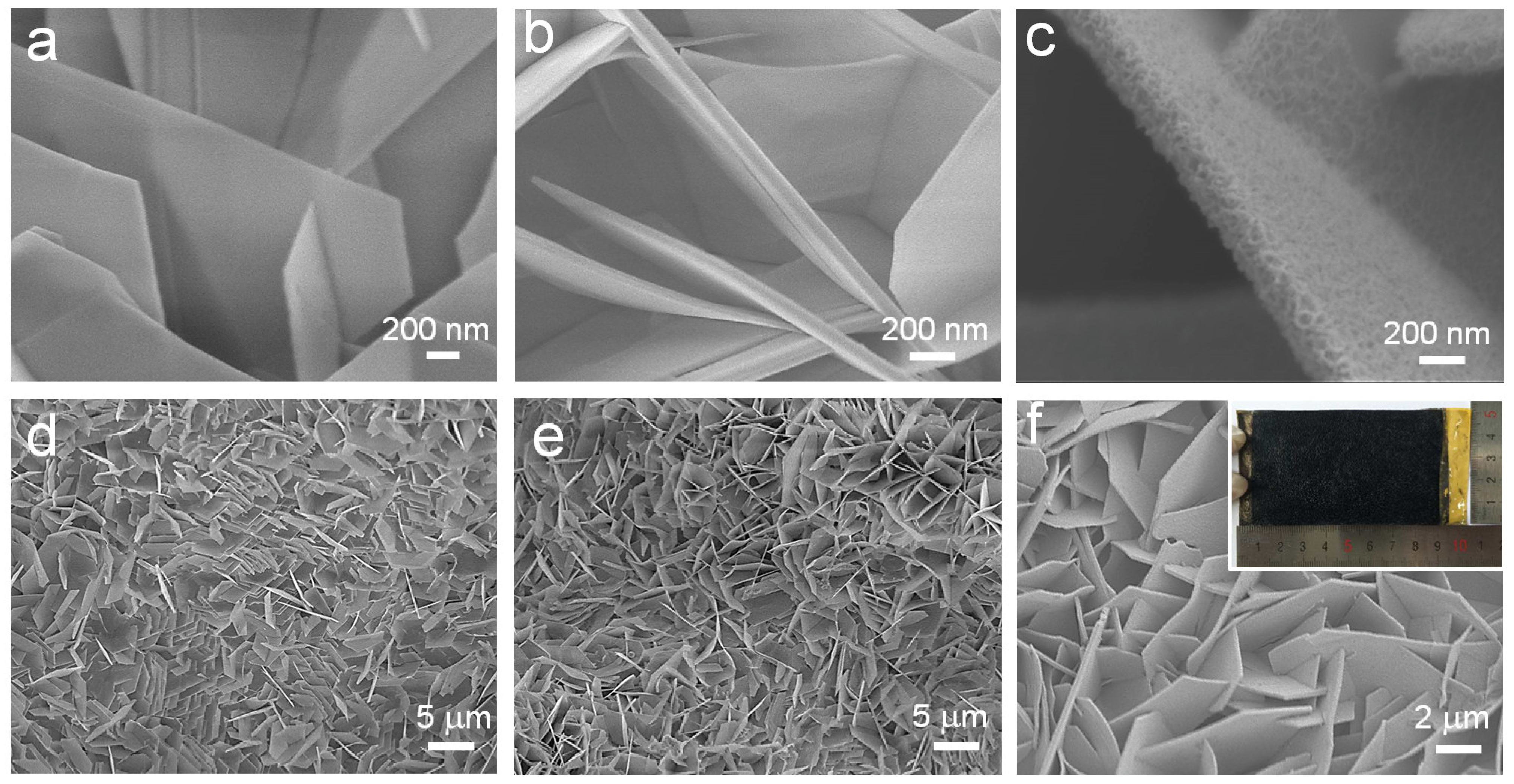
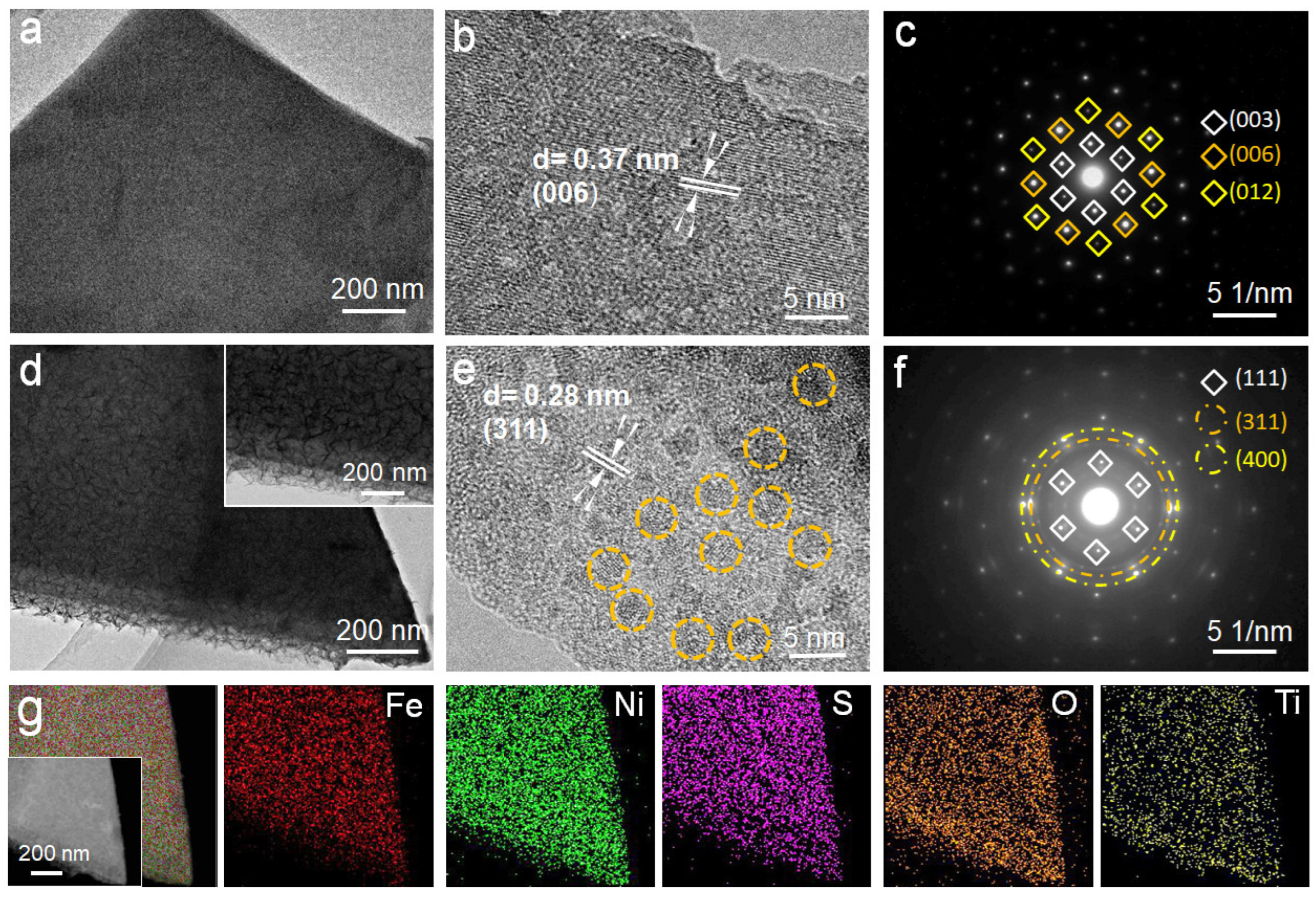
2.1. Morphology and Structure Analyses

The preparation process of integrated TiO2@FNS arrays is schematically illustrated in Figure 1. Firstly, the Fe2Ni2CO3(OH)8 (FNC) nanosheet precursor on nickel foam is fabricated via a facile hydrothermal process with Fe(NO3)2 as the Fe resource. Especially, Fe2+ ions react with Ni2+ ions provided by Ni foam substrate to form the final FNC nanosheet arrays. Afterward, an ALD method is used to construct a uniform TiO2 coating on the surface of FNC nanosheet (TiO2@FNC). After a simple low-temperature sulfurization process, the TiO2@FNC is converted to final TiO2@FNS branch nanoflake arrays.
The morphology change in different samples can be observed by their scanning electron microscope (SEM) images (Figure 2). The large FNC nanosheets with thickness of 30–60 nm are developed vertically on the surface of Ni foam substrate, forming a three-dimensional porous and open structure (Figure 2a,d). With a TiO2 coating, the thickness of the TiO2@FNC nanosheet increases to 40~70 nm, and the porous network structure is still perfectly preserved (Figure 2b,e), suggesting that the ALD process has no effect on the morphology structure. Different from the TiO2@FNC, the morphology of final TiO2@FNS arrays changed radically after the final sulfurization in Na2S solution at 90 °C. Obviously, numerous small nanoflakes are distributed on the outer layer to form a novel TiO2@FNS branch nanoflake arrays structure (Figure 2c,f). Moreover, the TiO2@FNS sample is ~50 cm2 with black color (the inset in Figure 2f), indicating our preparation process can be easily adapted for large-scale production.
Transmission electron microscope (TEM) images provide us with further insight into the structure of FNC and TiO2@FNS at the nanoscale. The FNC exhibits a nanosheet structure with a smooth surface (Figure 3a). Meanwhile, the measured interplanar d-spacing is ~0.37 nm (Figure 3b), which is in good agreement with the (006) plane of Fe2Ni2CO3(OH)8 phase. In the selected area electron diffraction (SAED) pattern (Figure 3c), obvious diffraction spots can be observed, matching well with the (003), (006) and (012) planes of Fe2Ni2CO3(OH)8 [25].
As for TiO2@FNS arrays, the internal TiO2 core is homogeneously coated by the cross-linked FNS nanoflakes (Figure 3d). A clear interplanar d-spacing of ~0.28 nm is observed in the HRTEM image (Figure 3e), corresponding to (311) plane of FeNi2S4 phase. Moreover, the diffraction rings in Figure 3f reveals the amorphous and polycrystal property of FNS, respectively corresponding to the (111), (311) and (400) facets of FeNi2S4 [26]. In addition, energy dispersive X-ray (EDS) mapping images (Figure 3g) demonstrate the uniform distribution of Fe, Ni, S, O and Ti elements in the TiO2@FNS core-branch arrays.
X-ray diffraction (XRD) and X-ray photoelectron spectroscopy (XPS) were performed to confirm the phase and composition of TiO2@FNS branch nanoflake arrays. As shown in Figure 4a, apart from the peaks of Ni foam, other diffraction peaks match well with Fe2Ni2CO3(OH)8 phase (JCPDS 49-0188) [27]. After ALD and sulfurization process, new diffraction peaks correspond to FeNi2S4 phase (JCPDS 47-1740) [28], revealing the successful preparation of FNS. Note that no diffraction peaks of TiO2 can be observed due to its amorphous feature. The composition of FNS branch arrays is further verified by XPS results. Figure 4b exhibits the high-resolution Ni 2p spectra of the TiO2@FNS branch nanoflake arrays. In addition to two shake-up satellite peaks, the peaks located at 873.48 and 856.08 eV belong to Ni 2p1/2 and Ni 2p3/2, respectively. Moreover, two smaller peaks are indexed to 853.28 and 872.28 eV, suggesting the co-existence of Ni2+/Ni3+ [29]. According to Gaussian fitting, the high-resolution Fe 2p spectra shows four peaks (Figure 4c), in which the peaks at 711.08 eV and 724.48 eV are in good agreement with the Fe2+ [30], while the peaks indexed to 713.18 and 726.68 eV match well with the Fe3+ species[31]. As for the S 2p spectra (Figure 4d), two peaks at 162.74 eV (S 2p1/2) and 161.68 eV (S 2p3/2) are observed, being consistent with the S2- [29]. In addition, the O 1s and Ti 2p spectra are detected in the TiO2@FNS branch nanoflake arrays. Two core levels at 530.78 and 531.59 eV match well with Ti-O bond and O-H bond, respectively (Figure 4e) [32].Ti 2p3/2 (458.03 eV) and Ti 2p1/2 (463.73 eV) characteristic peaks in Figure 4f further confirm the existence of TiO2 [33]. All these results mutually prove the successful fabrication of TiO2@FNS arrays.

2.2. Electrochemical Performance Analyses

The HER activity of TiO2@FNS was assessed in a three-electrode cell with 1 M KOH solution as the electrolyte. FNC and FNS on Ni foam were also directly used as the test electrodes to evaluate their HER electrocatalytic performances for comparison.
As exhibited in Figure 5a, TiO2 shows a negligible HER activity. Moreover, compared with FNC, FNS and TiO2@NS counterparts, our fabricated TiO2@FNS sample displays the best HER performance with the lowest overpotential of 97 mV at 10 mA cm−2. The effective electrochemical active surface areas (ECSA) of all samples were estimated by testing the double-layer capacitance (Cdl) based on the CV results at different scan rates. As shown in Figure 5b, the ECSA value is deemed to the half of the slope value. The TiO2@FNS branch nanoflake electrode possesses an ECAS value of 51 mF cm−2, much larger than the TiO2 (4 mF cm−2), FNC (14 mF cm−2), FNS (31 mF cm−2) and TiO2@NS (42 mF cm−2) [34] electrodes. Moreover, even compared with other reported HER electrocatalysts (CoP [35], NiS2 [36], Co9S8 [37], Ni3S2 [38], CoS [39], MoSe2 [40], Mo2C [41] and Ni0.7Fe0.3S2 [42]), our TiO2@FNS core-branch arrays still exhibit a superior HER property (Figure 5c). Low charge-transfer resistance is a characteristic of an effective electrocatalyst, especially a C-free electrocatalyst. Thus, electrochemical impendence spectroscopy was conducted to obtain charge-transfer data. Obviously, the TiO2@FNS electrode shows a smaller semicircular diameter than TiO2, FNC, FNS, and TiO2@NS samples (Figure 5d), suggesting that the introduction of TiO2 contributes to the optimized electronic structure. In addition, the TiO2@FNS core-branch electrode shows a remarkable long-term durability with no obvious fluctuation of overpotential and maintains a current density of 10 mA cm−2 in the HER over a 10 h durability test (Figure 5e). Furthermore, TiO2@FNS electrode still remains intact core-branch structure and intrinsic element composition after a 10 h test (Figure S1), demonstrating its high structural stability. Such excellent HER activity and structural stability of TiO2@FNS branch nanoflake arrays are owing to the increased specific surface area and the introduced TiO2 coating.

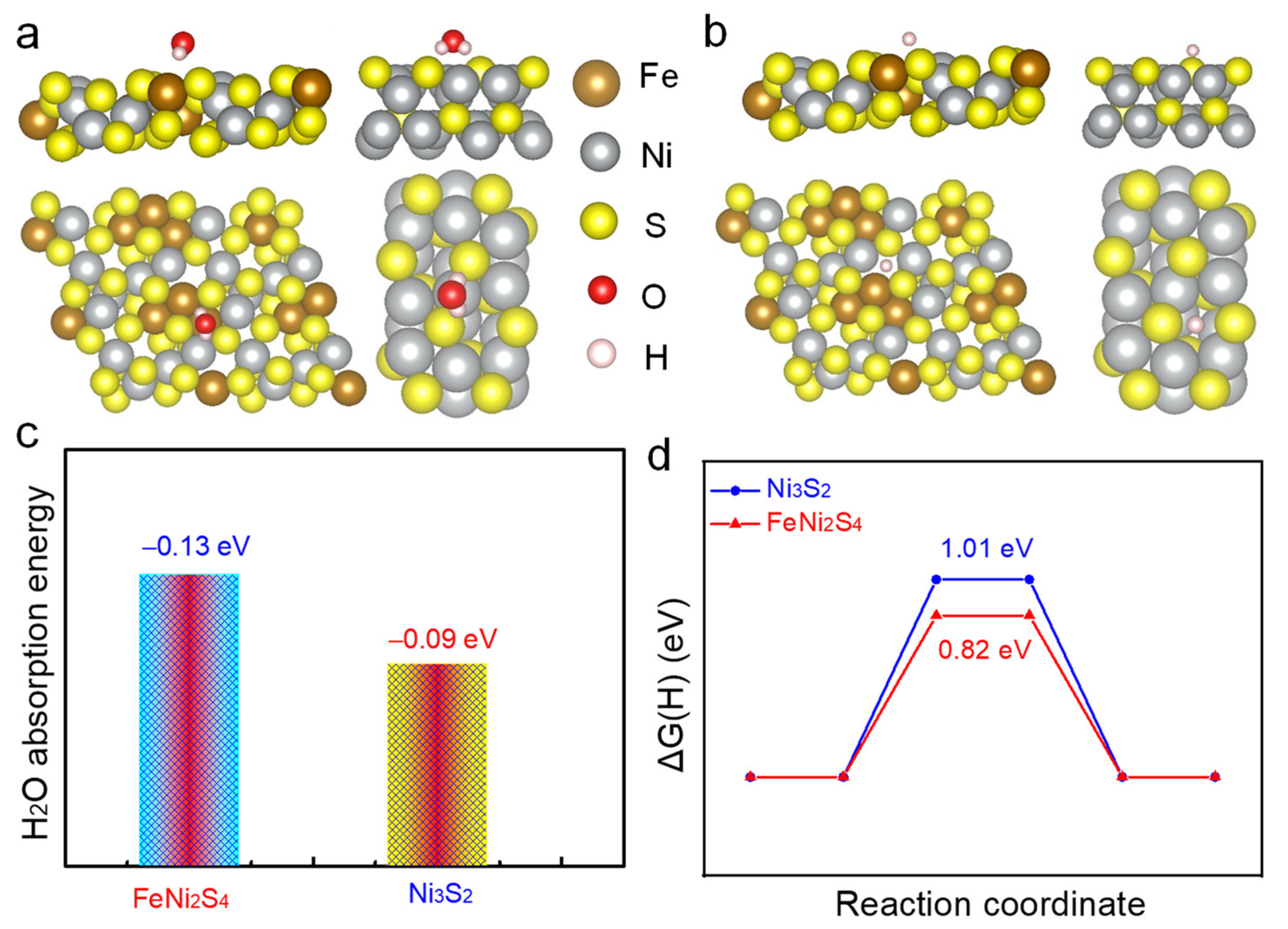
2.3. DFT Calculation

In order to obtain a deep understanding of superior HER activity for TiO2@FNS, we use the DFT calculation to investigate its water adsorption property and H proton adsorption/desorption property. It is well known that the adsorption energy of water molecules and H protons are the critical descriptors for HER in alkaline electrolyte. Figure 6a,b shows the water and H proton adsorption model of FeNi2S4, respectively. As shown in Figure 6c, the FeNi2S4 exhibits a water molecule adsorption energy of −0.13 eV, larger than the monometallic Ni3S2 (−0.09 eV). In addition, compared with monometallic Ni3S2 (1.01 eV), the FeNi2S4 also possesses a smaller H proton adsorption energy of 0.82 eV (Figure 6d). These results reveal that bimetallic FeNi2S4 can promote the dissociation of water molecule and the desorption of H, thereby displaying a higher intrinsic HER catalytic activity.

3. Materials and Methods

3.1. Synthesis of TiO2@FNS Arrays on Ni Foam

First, the growth precursor of Fe2Ni2CO3(OH)8 (FNC) nanosheet arrays were prepared by a simple hydrothermal method. Here, 3 mmol Fe(NO3)2, 6 mmol NH4F and 15 mmol urea were dissolved in 80 mL deionized water to form a homogeneous solution. Moreover, the Ni foam was used as the substrate and Ni source. Then, the above solution and Ni foam were transferred into a Teflon-linked steel autoclave and kept at 120 °C for 8 h to form FNC nanosheet arrays. Then the obtained FNC nanosheet arrays were placed in the ALD reactor (ALD PICOSUN P-300F, Espoo, Finland) with TiCl4 and H2O as the titanium source and O source, respectively. The TiO2 was deposited at 120 °C for 140 cycles. Argon was used as the carrier gas. Then, the obtained TiO2@FNC film underwent a low-temperature sulfurization process by immersing into 0.1 M Na2S solution at 90 °C for 12 h to form the final TiO2@FNS branch nanoflake arrays. For comparison, the pure FNS nanosheet arrays were fabricated by the same sulfurization procedure as above without TiO2 layer.

3.2. Characterization

The morphology and microstructure of all the samples were characterized by field emission scanning electron microscope (FESEM, Hitachi SU8010, Tokyo, Japan) and transmission electron microscope (TEM, JEOL 2100F, Tokyo, Japan). X-ray diffraction (XRD) reactor with Cu Kα radiation (Rigaku D/Max-2550, Shimadzu, Kyoto, Japan) was used to monitor the phase of all the samples. X-ray photoelectron spectroscopy was also performed to study the valence of samples by using an Al Kα source of 1486.6 eV (Thermo Fisher Scientific, Waltham, MA, USA).

3.3. Electrochemical Measurements

All samples were used as the test electrode directly and the electrochemical measurements were conducted in a three-electrode configuration at room temperature with Pt foil and saturated calomel electrode (SCE) as the contrast and reference electrode, respectively. One (1) M KOH solution was used as the electrolyte. The E(SCE) was turned into E(RHE) based on the following equation: E(RHE) = E(SCE) + 1.0714 V. Electrodes were first scanned by CV test at a scan rate of 100 mV s−1 over 10 cycles to stabilize the current. Linear sweep voltammetry (LSV) tests were tested at a scan rate of 1 mV s−1. Tafel plots were obtained from LSV curves. The stability test was performed at a constant current density of 10 mA cm−2. The above test results were obtained by iR-compensation. The effective electrochemical active surface area (ECSA) value was equal to half of the slope value, which was obtained according to a function relationship between the measured current and scan rates.

3.4. Computational Methods and Models

Density functional theory (DFT) calculations were performed using the quantum espresso (QE) [43,44] based on the pseudopotential plane wave (PPW) method. The Perdew-Bueke-Ernzerhof (PBE) functional [45] was used to describe exchange-correlation effects of electrons. We have chosen the projected augmented wave (PAW) potentials [46,47] to describe the ionic cores and take valence electrons into account using a plane wave basis set with a kinetic energy cutoff of 500 eV.

4. Conclusions

In summary, we have demonstrated a simple approach using ALD and sulfurization to fabricate a novel TiO2@FNS branch nanoflake arrays on a large scale, in which the TiO2 coating provides a key for enhancing the HER performance of integrated electrode. Due to the increased specific surface area and improved structural stability, the obtained TiO2@FNS branch nanoflake arrays exhibit noticeable HER activity in alkaline medium with a low overpotentials (97 mV at 10 mA cm−2), much superior to FNS and other reported electrocatalysts. We believe our work will give valuable insights for developing superior HER catalysts and beyond.

Supplementary Materials

The following supporting information can be downloaded at: https://www.mdpi.com/article/10.3390/catal13010174/s1, Figure S1. (a) SEM image and (b) XPS survey of TiO2@FNS electrode after 10 h-durability test.

Author Contributions

data curation, S.D., C.L. and Y.J.; writing-original draft preparation, S.D., Z.Y. and C.L.; writing-review and editing, Y.Z., B.M. and S.L.; supervision, Y.Z., B.M. and S.L.; project administration, S.L.; funding acquisition, S.L. and Y.J. All authors have read and agreed to the published version of the manuscript.

Funding

This research was funded by the specific research fund of the Innovation Platform for Academicians of Hainan Province (YSPTZX202123), the Innovation center for Academician team of Hainan Province and the Hainan Provincial Innovative Research Project of Postgraduates (No. Qhys2021-160).

Data Availability Statement

The datasets generated during and/or analyzed during the current study are available from the corresponding author on reasonable request.

Conflicts of Interest

The authors declare no conflict of interest.

References

  1. Li, C.; Wang, Z.; Liu, M.; Wang, E.; Wang, B.; Xu, L.; Jiang, K.; Fan, S.; Sun, Y.; Li, J.; et al. Ultrafast self-heating synthesis of robust heterogeneous nanocarbides for high current density hydrogen evolution reaction. Nat. Commun. 2022, 13, 3338. [Google Scholar] [CrossRef] [PubMed]
  2. Yang, X.; Cheng, J.; Yang, X.; Xu, Y.; Sun, W.; Zhou, J. Facet-tunable coral-like Mo2C catalyst for electrocatalytic hydrogen evolution reaction. Chem. Eng. J. 2023, 451, 138977. [Google Scholar] [CrossRef]
  3. Zhao, G.; Rui, K.; Dou, S.X.; Sun, W. Heterostructures for Electrochemical Hydrogen Evolution Reaction: A Review. Adv. Funct. Mater. 2018, 28, 1803291. [Google Scholar] [CrossRef] [Green Version]
  4. Che, S.; Ta, N.; Yang, F.; Yang, Y.; Li, Y. I Interfacial electronic engineering of NiSe–anchored Ni–N–C composite electrocatalyst for efficient hydrogen evolution. Catalysts 2022, 12, 1525. [Google Scholar] [CrossRef]
  5. Zhou, Q.; Bian, Q.; Liao, L.; Yu, F.; Li, D.; Tang, D.; Zhou, H. In situ electrochemical dehydrogenation of ultrathin Co(OH)2 nanosheets for enhanced hydrogen evolution. Chin. Chem. Lett. 2023, 34, 107248. [Google Scholar] [CrossRef]
  6. Tong, Y.; Liu, J.; Wang, L.; Su, B.-J.; Wu, K.-H.; Juang, J.-Y.; Hou, F.; Yin, L.; Dou, S.; Liu, J.; et al. Carbon-Shielded Single-Atom Alloy Material Family for Multi-Functional Electrocatalysis. Adv. Funct. Mater. 2022, 32, 2205654. [Google Scholar] [CrossRef]
  7. Karmodak, N.; Andreussi, O. Catalytic Activity and Stability of Two-Dimensional Materials for the Hydrogen Evolution Reaction. ACS Energy Lett. 2020, 5, 885–891. [Google Scholar] [CrossRef]
  8. Zeng, F.; Mebrahtu, C.; Liao, L.; Beine, A.K.; Palkovits, R. Stability and deactivation of OER electrocatalysts: A review. J. Energy Chem. 2022, 69, 301–329. [Google Scholar] [CrossRef]
  9. Xu, Z.; Hao, M.; Liu, X.; Ma, J.; Wang, L.; Li, C.; Wang, W. Co(OH)2 nanoflowers decorated α-NiMoO4 nanowires as a bifunctional electrocatalyst for efficient overall water splitting. Catalysts 2022, 12, 1417; [Google Scholar] [CrossRef]
  10. Li, C.; Jang, H.; Kim, M.G.; Hou, L.; Liu, X.; Cho, J. Ru-incorporated oxygen-vacancy-enriched MoO2 electrocatalysts for hydrogen evolution reaction. Appl. Catal. B Environ. 2022, 307, 121204. [Google Scholar] [CrossRef]
  11. Ye, J.; Zang, Y.; Wang, Q.; Zhang, Y.; Sun, D.; Zhang, L.; Wang, G.; Zheng, X.; Zhu, J. Nitrogen doped FeS2 nanoparticles for efficient and stable hydrogen evolution reaction. J. Energy Chem. 2020, 56, 283–289. [Google Scholar] [CrossRef]
  12. Liao, L.; Zhao, Y.; Zhou, H.; Li, D.; Qi, Y.; Zhang, Y.; Sun, Y.; Zhou, Q.; Yu, F. Edge-oriented N-Doped WS2 Nanoparticles on Porous Co3N Nanosheets for Efficient Alkaline Hydrogen Evolution and Nitrogenous Nucleophile Electrooxidation. Small 2022, 18, 2203171. [Google Scholar] [CrossRef] [PubMed]
  13. Zhou, H.; Wang, Y.; He, R.; Yu, F.; Sun, J.; Wang, F.; Lan, Y.; Ren, Z.; Chen, S. One-step synthesis of self-supported porous NiSe2/Ni hybrid foam: An efficient 3D electrode for hydrogen evolution reaction. Nano Energy 2016, 20, 29–36. [Google Scholar] [CrossRef]
  14. Deng, S.; Yang, F.; Zhang, Q.; Zhong, Y.; Zeng, Y.; Lin, S.; Wang, X.; Lu, X.; Wang, C.-Z.; Gu, L.; et al. Phase Modulation of (1T-2H)-MoSe2/TiC-C Shell/Core Arrays via Nitrogen Doping for Highly Efficient Hydrogen Evolution Reaction. Adv. Mater. 2018, 30, 1802223. [Google Scholar] [CrossRef] [Green Version]
  15. Zang, Y.; Yang, B.; Li, A.; Liao, C.; Chen, G.; Liu, M.; Liu, X.; Ma, R.; Zhang, N. Tuning Interfacial Active Sites over Porous Mo2N-Supported Cobalt Sulfides for Efficient Hydrogen Evolution Reactions in Acid and Alkaline Electrolytes. ACS Appl. Mater. Interfaces 2021, 13, 41573–41583. [Google Scholar] [CrossRef]
  16. Liu, Z.; Li, J.; Xue, S.; Zhou, S.; Qu, K.; Li, Y.; Cai, W. Pt/Mo2C heteronanosheets for superior hydrogen evolution reaction. J. Energy Chem. 2020, 47, 317–323. [Google Scholar] [CrossRef]
  17. Liu, W.; Geng, P.; Li, S.; Liu, W.; Fan, D.; Lu, H.; Lu, Z.; Liu, Y. Tuning electronic configuration of WP2 nanosheet arrays via nickel doping for high-efficiency hydrogen evolution reaction. J. Energy Chem. 2020, 55, 17–24. [Google Scholar] [CrossRef]
  18. Lin, L.; Sherrell, P.; Liu, Y.; Lei, W.; Zhang, S.; Zhang, H.; Wallace, G.G.; Chen, J. Engineered 2D Transition Metal Dichalcogenides—A Vision of Viable Hydrogen Evolution Reaction Catalysis. Adv. Energy Mater. 2020, 10, 1903870. [Google Scholar] [CrossRef]
  19. Morozan, A.; Johnson, H.; Roiron, C.; Genay, G.; Aldakov, D.; Ghedjatti, A.; Nguyen, C.T.; Tran, P.D.; Kinge, S.; Artero, V. Nonprecious Bimetallic Iron–Molybdenum Sulfide Electrocatalysts for the Hydrogen Evolution Reaction in Proton Exchange Membrane Electrolyzers. ACS Catal. 2020, 10, 14336–14348. [Google Scholar] [CrossRef]
  20. Yang, H.; Driess, M.; Menezes, P.W. Self-Supported Electrocatalysts for Practical Water Electrolysis. Adv. Energy Mater. 2021, 11, 2102074. [Google Scholar] [CrossRef]
  21. Sivanantham, A.; Ganesan, P.; Shanmugam, S. Hierarchical NiCo2S4Nanowire Arrays Supported on Ni Foam: An Efficient and Durable Bifunctional Electrocatalyst for Oxygen and Hydrogen Evolution Reactions. Adv. Funct. Mater. 2016, 26, 4661–4672. [Google Scholar] [CrossRef]
  22. Zhao, Y.; Mavrokefalos, C.K.; Zhang, P.; Erni, R.; Li, J.; Triana, C.A.; Patzke, G.R. Self-Templating Strategies for Transition Metal Sulfide Nanoboxes as Robust Bifunctional Electrocatalysts. Chem. Mater. 2020, 32, 1371–1383. [Google Scholar] [CrossRef]
  23. Su, H.; Song, S.; Gao, Y.; Li, N.; Fu, Y.; Ge, L.; Song, W.; Liu, J.; Ma, T. In Situ Electronic Redistribution Tuning of NiCo2S4 Nanosheets for Enhanced Electrocatalysis. Adv. Funct. Mater. 2022, 32, 2109731. [Google Scholar] [CrossRef]
  24. Jadhav, H.S.; Roy, A.; Thorat, G.M.; Chung, W.-J.; Gil Seo, J. Hierarchical free-standing networks of MnCo2S4 as efficient Electrocatalyst for oxygen evolution reaction. J. Ind. Eng. Chem. 2018, 71, 452–459. [Google Scholar] [CrossRef]
  25. Li, L.; Dai, Y.; Xu, Q.; Zhang, B.; Zhang, F.; You, Y.; Ma, D.; Li, S.-S.; Zhang, Y.-X. Interlayer expanded nickel-iron layered double hydroxide by intercalation with sodium dodecyl sulfate for enhanced oxygen evolution reaction. J. Alloy. Compd. 2021, 882, 160752. [Google Scholar] [CrossRef]
  26. Liu, Y.; Li, Y.; Srinivas, K.; Wang, M.; Liu, D.; Chen, X.; Wang, B.; Wang, S.; Chen, Y. Heterogeneous FeNi2S4/Ni3S4 nanoparticles embedded CNT networks for efficient and stable water oxidation. Journal Alloys Compounds 2022, 914, 165327. [Google Scholar] [CrossRef]
  27. Ren, L.; Wang, C.; Li, W.; Dong, R.; Sun, H.; Liu, N.; Geng, B. Heterostructural NiFe-LDH@Ni3S2 nanosheet arrays as an efficient electrocatalyst for overall water splitting. Electrochim. Acta 2019, 318, 42–50. [Google Scholar] [CrossRef]
  28. Jiang, J.; Zhang, Y.-J.; Zhu, X.-J.; Lu, S.; Long, L.-L.; Chen, J.-J. Nanostructured metallic FeNi2S4 with reconstruction to generate FeNi-based oxide as a highly-efficient oxygen evolution electrocatalyst. Nano Energy 2020, 81, 105619. [Google Scholar] [CrossRef]
  29. Wu, Y.; Li, Y.; Yuan, M.; Hao, H.; San, X.; Lv, Z.; Xu, L.; Wei, B. Operando capturing of surface self-reconstruction of Ni3S2/FeNi2S4 hybrid nanosheet array for overall water splitting. Chem. Eng. J. 2022, 427, 131944. [Google Scholar] [CrossRef]
  30. Yu, F.; Zhou, H.; Zhu, Z.; Sun, J.; He, R.; Bao, J.; Chen, S.; Ren, Z. Three-Dimensional Nanoporous Iron Nitride Film as an Efficient Electrocatalyst for Water Oxidation. ACS Catal. 2017, 7, 2052–2057. [Google Scholar] [CrossRef]
  31. Liu, C.; Jia, D.; Hao, Q.; Zheng, X.; Li, Y.; Tang, C.; Liu, H.; Zhang, J.; Zheng, X. P-Doped Iron–Nickel Sulfide Nanosheet Arrays for Highly Efficient Overall Water Splitting. ACS Appl. Mater. Interfaces 2019, 11, 27667–27676. [Google Scholar] [CrossRef] [PubMed]
  32. Ma, B.; Guan, P.-Y.; Li, Q.-Y.; Zhang, M.; Zang, S.-Q. MOF-Derived Flower-like MoS2@TiO2 Nanohybrids with Enhanced Activity for Hydrogen Evolution. ACS Appl. Mater. Interfaces 2016, 8, 26794–26800. [Google Scholar] [CrossRef] [PubMed]
  33. Gao, S.; Zavabeti, A.; Wang, B.; Ren, R.; Yang, C.; Liu, Z.; Wang, Y. Nickel Phosphides Electrodeposited on TiO2 Nanotube Arrays as Electrocatalysts for Hydrogen Evolution. ACS Appl. Nano Mater. 2021, 4, 4542–4551. [Google Scholar] [CrossRef]
  34. Deng, S.; Zhang, K.; Xie, D.; Zhang, Y.; Zhang, Y.; Wang, Y.; Wu, J.; Wang, X.; Fan, H.J.; Xia, X.; et al. High-Index-Faceted Ni3S2 Branch Arrays as Bifunctional Electrocatalysts for Efficient Water Splitting. Nano-Micro Lett. 2019, 11, 12. [Google Scholar] [CrossRef] [Green Version]
  35. Li, J.; Zou, S.; Liu, X.; Lu, Y.; Dong, D. Electronic Modulation of CoP by Ce Doping as Highly Efficient Electrocatalysts for Water Splitting. ACS Sustain. Chem. Eng. 2020, 8, 10009–10016. [Google Scholar] [CrossRef]
  36. Tian, T.; Huang, L.; Ai, L.; Jiang, J. Surface anion-rich NiS2 hollow microspheres derived from metal–organic frameworks as a robust electrocatalyst for the hydrogen evolution reaction. J. Mater. Chem. A 2017, 5, 20985–20992. [Google Scholar] [CrossRef]
  37. Yang, Y.; Yuan, M.; Li, H.; Sun, G.; Ma, S. Controllable synthesis of ultrathin Co9S8 nanosheets as a highly efficient electrocatalyst for overall water splitting. Electrochim. Acta 2018, 281, 198–207. [Google Scholar] [CrossRef]
  38. Li, L.; Sun, C.; Shang, B.; Li, Q.; Lei, J.; Li, N.; Pan, F. Tailoring the facets of Ni3S2 as a bifunctional electrocatalyst for high-performance overall water-splitting. J. Mater. Chem. A 2019, 7, 18003–18011. [Google Scholar] [CrossRef]
  39. Li, N.; Liu, X.; Li, G.-D.; Wu, Y.; Gao, R.; Zou, X. Vertically grown CoS nanosheets on carbon cloth as efficient hydrogen evolution electrocatalysts. Int. J. Hydrogen Energy 2017, 42, 9914–9921. [Google Scholar] [CrossRef]
  40. Yin, Y.; Zhang, Y.; Gao, T.; Yao, T.; Zhang, X.; Han, J.; Wang, X.; Zhang, Z.; Xu, P.; Zhang, P.; et al. Synergistic Phase and Disorder Engineering in 1T-MoSe2 Nanosheets for Enhanced Hydrogen-Evolution Reaction. Adv. Mater. 2017, 29, 1700311. [Google Scholar] [CrossRef]
  41. Sun, J.; Liu, J.; Chen, H.; Han, X.; Wu, Y.; He, J.; Han, C.; Yang, G.; Shan, Y. Strongly coupled Mo2C and Ni nanoparticles with in-situ formed interfaces encapsulated by porous carbon nanofibers for efficient hydrogen evolution reaction under alkaline conditions. J. Colloid Interface Sci. 2019, 558, 100–105. [Google Scholar] [CrossRef]
  42. Yu, J.; Cheng, G.; Luo, W. Ternary nickel–iron sulfide microflowers as a robust electrocatalyst for bifunctional water splitting. J. Mater. Chem. A 2017, 5, 15838–15844. [Google Scholar] [CrossRef]
  43. Giannozzi, P.; Baroni, S.; Bonini, N.; Calandra, M.; Car, R.; Cavazzoni, C.; Ceresoli, D.; Chiarotti, G.L.; Cococcioni, M.; Dabo, I.; et al. QUANTUM ESPRESSO: A modular and open-source software project for quantum simulations of materials. J. Phys. Condens. Matter 2009, 21, 395502. [Google Scholar] [CrossRef] [PubMed]
  44. Giannozzi, P.; Andreussi, O.; Brumme, T.; Bunau, O.; Nardelli, M.B.; Calandra, M.; Car, R.; Cavazzoni, C.; Ceresoli, D.; Cococcioni, M.; et al. Advanced capabilities for materials modelling with Quantum ESPRESSO. J. Phys. Condens. Matter 2017, 29, 465901. [Google Scholar] [CrossRef] [PubMed] [Green Version]
  45. Perdew, J.P.; Burke, K.; Ernzerhof, M. Generalized gradient approximation made simple. Phys. Rev. Lett. 1996, 77, 3865. [Google Scholar] [CrossRef] [PubMed] [Green Version]
  46. Blöchl, P.E.; Jepsen, O.; Andersen, O.K. Improved tetrahedron method for Brillouin-zone integrations. Phys. Rev. B 1994, 49, 16223–16233. [Google Scholar] [CrossRef] [PubMed]
  47. Kresse, G.; Joubert, D. From ultrasoft pseudopotentials to the projector augmented-wave method. Phys. Rev. B 1999, 59, 1758–1775. [Google Scholar] [CrossRef]
Figure 1. Schematic illustration of the preparation process for binder-free TiO2@FNS arrays.
Catalysts 13 00174 g001
Figure 2. SEM images of (a,d) FNC, (b,e) TiO2@FNC and (c,f) TiO2@FNS arrays. The inset of (f) is the optical photograph for large-scale fabricated TiO2@FNS electrode.
Catalysts 13 00174 g002
Figure 3. (a) TEM image, (b) HRTEM image and (c) SAED pattern of FNC nanosheet; (d) TEM image, (e) HRTEM image, (f) SAED pattern and (g) EDS mapping images of TiO2@FNS core-branch nanosheet.
Catalysts 13 00174 g003
Figure 4. (a) XRD pattern of FNC and TiO2@FNS arrays. XPS spectra of TiO2@FNS arrays: (b) Ni 2p, (c) Fe 2p, (d) S 2p, (e) O 1s, and (f) Ti 2p.
Catalysts 13 00174 g004
Figure 5. (a) LSV curves and (b) the ratio of current density with various scan rates of TiO2, FNC, FNS, TiO2@NS and TiO2@FNS samples. (c) HER performance comparison of different materials. (d) EIS of TiO2, FNC, FNS, TiO2@NS and TiO2@FNS samples. (e) Cycling performance of TiO2@FNS electrode at 10 mA cm−2.
Catalysts 13 00174 g005
Figure 6. (a) Water molecule adsorption and (b) H proton adsorption model of FeNi2S4 (311) plane. (c) Water molecule adsorption energy and (d) H proton adsorption energy comparison results of FeNi2S4 and Ni3S2.
Catalysts 13 00174 g006
Disclaimer/Publisher’s Note: The statements, opinions and data contained in all publications are solely those of the individual author(s) and contributor(s) and not of MDPI and/or the editor(s). MDPI and/or the editor(s) disclaim responsibility for any injury to people or property resulting from any ideas, methods, instructions or products referred to in the content.

