1. Introduction
Zeolites are used in several large-scale industrial processes to catalyze the selective conversion of hydrocarbons into valuable chemicals and fuels [
1,
2]. The successful utilization of zeolites in both traditional and future applications benefits from the very small dimensions of the zeolitic micropores. These small zeolite pores allow for shape-selective hydrocarbon conversions by serving as molecular sieves. However, the same micropores have been reported to slow down the transport of reactants and products within the zeolite crystals and thereby, accelerating unwanted side reactions and deactivation of the catalyst [
3]. One way to reduce these problems is to use zeolites with small or nanosized dimensions.
Zeolites with small crystal dimensions have been reported to exhibit better catalytic performance than the micron-sized ones [
4,
5,
6]. Yet, micron-sized zeolites are still widely used and are the state-of-the-art zeolite catalysts used in industrial processes. This is mainly due to challenges associated with the preparation and handling of nanosized zeolites [
7].
A reduction in the dimensions of zeolite crystals can be achieved during synthesis or by post-synthetic treatments [
3,
7] Post-synthetic treatments are top-down approaches that mainly involve the milling of zeolite crystals with dimensions in the micrometer range [
8]. The preparation of nanosized zeolites during the synthesis mostly involves variations in synthesis temperature, time, or gel composition or the addition of growth inhibitors [
7]. Crystal growth has been limited by using special designed templates or by using confined space synthesis [
9,
10,
11]. Many of these templates are not yet commercially available and need to be synthesized. A more convenient and elegant way to prepare nanosized zeolites is to modify the synthesis procedure in order to vary the crystal size [
12,
13]. This has been achieved by increasing the alkalinity of the synthesis mixture and reducing the synthesis temperature. Such conditions usually result in high template consumption and low yields of nanosized zeolites. This means that a large fraction of the starting raw materials, i.e., silica and alumina sources, are not incorporated into the final zeolite product and are thus disposed of as waste [
14]. Moreover, the high alkalinity used needs to be neutralized after the synthesis. These issues increase the costs for the preparation of nanosized zeolites and poses serious environmental concerns.
Another concern in the industrial-scale production and utilization of nanosized zeolites is their recovery from the synthesis mixture and subsequent handling. Zeolites are usually recovered from the synthesis mixture via filtration. Depending on the intended application, the filtered product is dried and converted into the desired form and shape via several calcination, ion exchange and shaping steps. The successful utilization of these procedures depends very much on the size of the primary zeolite crystals. Ideally suited are those crystals, which can be easily separated without blocking the filters. This is the case for micrometer-sized zeolite crystals. For nanosized zeolite crystals, centrifugation is usually applied. This is, however, only possible for the synthesis on small, mainly laboratory, scale.
Thus, in developing sustainable processes for preparing nanosized zeolite arrangements, the yield must be maximized to reduce the production costs and the amount of waste. Moreover, the recovery of the nanosized zeolites and their shaping are issues of concern. One strategy to maximize the yield and reduce waste would be to recycle the synthesis waste stream, as suggested by Bein and coworkers [
14]. This requires the separation of the formed nanocrystals after each hydrothermal synthesis stage and readjustment of the molar composition of the synthesis mixture. The realization of these requirements can be challenging, especially on a technical scale.
Other attempts to overcome shaping, separation and low yield problems of hydrothermal synthesis have been reported in the literature. Zhang et al. reported the preparation of oriented self-assembled nanosized ZSM-5 zeolites using a salt-aided-seed-induced method [
15]. By using this approach, yields of up to 85% were achieved and the accessibility of the nano-crystallites during catalysis was improved [
15]. Self-assembled nanosized zeolites have also been prepared by using surfactants, organosilanes and polymers [
16,
17,
18]. Even the preparation of binder-free nanosized zeolites by using dry gel conversion and aerosol-assisted method has been reported [
19,
20]. Recently, Gascon et al. evaluated the application of spray drying to manufacture spherical ZSM-5-based catalysts and their applicability in the methanol-to-olefins process. Their main focus was the shaping process of the catalysts itself and the related impact on the catalysis [
21]. Another approach starts with a spray drying process of amorphous aluminosilicates encapsulating tetrapropylammonium hydroxide (TPAOH) and producing microspheres, which are than successfully transformed into robust zeolite-containing microspheres by using a steam-assisted crystallization (SAC) process [
22].
By contrast, Klumpp et al. reported an economical and environmental procedure to prepare hierarchical porous assemblies of zeolite silicalite-1 (MFI) nanocrystals by a spray drying and steam-assisted crystallization process [
23]. According to the authors, the nano zeolite suspension from the hydrothermal synthesis was initially completely spray dried to form spherical particles made up of nanosized zeolite particles and amorphous silica. These granulates were thereafter impregnated again with a microporogen (we chose this expression in accordance with the terms meso- or macroporogen here for the typical template TPAOH used for MFI crystallization) and subjected to steam-assisted crystallization to fully convert the amorphous silica into the zeolite. This procedure has several advantages: (i) the recovery and shaping of nanosized zeolite particles from the synthesis mixture can be accomplished in a single process step via spray drying; (ii) silica can be fully converted into zeolites in the subsequent steam-assisted crystallization step; and (iii) synthesis waste can be reduced significantly. According to the authors, the successful steam-assisted crystallization of the spray-dried granulates was only possible after additional impregnation with the microporogen template TPAOH. Furthermore, only the conversion of aluminum-free nanosized zeolites was demonstrated, which have less relevance in catalysis and their hydrothermal syntheses already give high yields. Very recently, a strategy was demonstrated to produce hierarchical highly porous ZSM-5 microspheres by a combination of two processes: spray-freeze drying and steaming-assisted crystallization (SAC) [
24,
25].
The main goal of the current work is now to utilize the strengths of the method reported by Klumpp et al. [
23], i.e., the combination of spray drying and steam-assisted crystallization to improve the efficiency of the hydrothermal synthesis even of aluminum-containing nanosized zeolites. The target is to maximize the overall yield of nanosized zeolite arrangements and reduce the amount of waste produced after hydrothermal synthesis.
Scheme 1 illustrates the process steps employed. Firstly, a hydrothermal synthesis of nanosized ZSM-5 material has been conducted. This zeolite has been selected as a model system, but the developed procedure is applicable even to other zeolite types. Initially, the hydrothermal synthesis of nanosized zeolites has been studied and scaled up. Thereafter, proper spray drying conditions were screened to prevent excessive decomposition of the template left from hydrothermal synthesis. This is necessary to avoid the extra addition of the template prior to the steam-assisted crystallization step. In this regard, the process reported here is, compared to the one proposed earlier by Klumpp et al. [
23], optimized. Finally, in a third step, the subsequent transformation of unconverted SiO
2 into nanosized zeolite aggregates via SAC is studied.
2. Results
2.1. Preparation of Nanosized ZSM-5 via Hydrothermal Synthesis
The main goal of the current work is to utilize the strengths of spray drying and steam-assisted crystallization (dry gel conversion) techniques to improve the efficiency of the hydrothermal synthesis of nanosized aluminum-containing zeolites. Specifically, the yield of nanosized zeolites should be maximized, while the amount of waste produced will be reduced. To achieve this goal, systematic studies on the hydrothermal synthesis of nanosized zeolites were conducted. The main interest is in showing the problems associated with hydrothermal synthesis of nanosized zeolites, i.e., the low yield obtained from this well-established method for preparing zeolites. The influence of aging time, synthesis time and Si/Al ratio on the yield and crystallinity of the nanosized zeolites, as well as the scaling up of this process, is studied.
Figure 1 shows the XRD patterns of dried suspensions collected after different times of hydrothermal synthesis. All observed reflections can be assigned to MFI-type zeolite. This confirms that MFI is the only crystalline phase formed independent of the used aging time. Depending on the aging time; however, these reflections appeared and increased differently. The sample with the longest aging time was the first to form the MFI phase. After about 15 h of synthesis, MFI reflections were observed in the patterns of all samples. By further increasing the synthesis time, the intensity of these reflections increased and reached a maximum after 22 h. However, the maximum intensity reached was a function of the aging time. The highest intensities were observed on the diffraction patterns of the samples with longer aging times. These results are further summarized in
Figure 2, which shows the crystallinities reached at each aging time as a function of synthesis time. Up to a synthesis time of 10 h, a very slow increase in crystallinity was observed. As the synthesis time was further increased to 15 h, a very sharp gain in crystallinity was observed for all samples. However, the increase in the crystallization rate depends on the aging time. The highest rate was observed for the sample aged for 96 h. A further extension of the synthesis time resulted in just moderate gain in crystallinity, and after 22 h almost a plateau is reached. Another interesting observation is that the maximum crystallinity reached is a function of the aging time and was around 50% for the sample with the longest aging time. In this work, yield is regarded as equivalent to the crystallinity as subsequently described in the experimental section.
The above observations show that longer aging time results in shorter synthesis times, and can influence the yield of nanocrystals. Nevertheless, the maximum yield that can be reached for the displayed Si/Al ratio of 100 is around 50%. This means that half of the starting material will be disposed as waste. This poses serious economic and environmental concerns. Thus, ways to fully utilize the starting raw materials and thereby increase the yield of nanosized zeolites are sought after. For further investigations, gels aged for about 1 h, which actually gave the lowest yield, and a synthesis time of 22 h were used to prepare nanosized zeolites with different Si/Al ratios at a large scale in a 2 L autoclave.
The intensity in the diffraction patterns of products collected after 22 h of synthesis time depends on the Si/Al ratio of the starting gel (
Figure 3). As the Si/Al ratio is decreased, both the maximum crystallinity and size of the nanocrystals decrease (
Figure 3b–e). This behavior is well known for the preparation of conventional zeolite crystals. However, the strong dependency of the crystallinity and yield on the Si/Al ratio is unique to nanosized zeolites and further demonstrates the challenges associated with the preparation of these promising materials. From
Figure 3b, it can be seen that almost 80% of the starting raw materials were converted into nanosized zeolites with a Si/Al ratio of 200. This is close to full conversion, since the sample still contains a significant amount of the template. However, at low Si/Al ratios, yields of about 35% were obtained. A similar trend was also observed in the work of Persson et al. [
13]. The following discussion will show how spray drying and SAC technique can be used to maximize this low yield to 100%. This has been achieved by spray drying the nano zeolite suspension from hydrothermal synthesis followed by steam-assisted conversion (SAC).
2.2. Spray Drying of Nanosized Zeolite Suspension from Hydrothermal Synthesis
To overcome technical problems associated with the separation and shaping of nanosized zeolites, the whole reaction mixture, including the mother liquor, from hydrothermal synthesis was directly spray- dried. After spray drying, the resulting spherical particles are expected to be composed of aggregated nanosized ZSM-5, organic template, and amorphous silica (
Figure 4a). Although the obtained spay dried particles have a broader particle size distribution, they can easily be handled by using common techniques like filtration. In contrast, the powder obtained after drying the suspension at 90 °C for 16 h (
Figure 4b) shows the presence of poorly ordered primary nanoparticles embedded in an amorphous silica phase. Such powders are very difficult to separate via filtration. Consequently, spray drying was used to simultaneously separate and shape nanosized zeolites. However, the collected spray-dried powder contained nanosized zeolite crystals, amorphous silica and alumina as well as organic material. The unconverted silica and alumina may reduce the accessibility of the nanosized zeolites and may accelerate unwanted side reactions, especially during catalysis. Therefore, before such spray-dried zeolites can be used as catalysts, the enclosed amorphous material must be either removed or converted into the zeolite phase. Although the removal of amorphous material is possible, it may result in the loss of integrity of such spheres and increase the amount of waste. Thus, the full conversion into the zeolite phase is the preferred option.
For the conversion of this amorphous material into spray-dried particles, the presence of the template and alkaline media is needed. Usually, these two components need to be added additionally after spray drying the suspension, as already shown by Klumpp et al. [
23]. This is due to the excessive loss of the template during spray drying. The other option is to avoid this extra addition of template and instead try to utilize the template left after hydrothermal synthesis. This can be realized if excessive decomposition of the template can be avoided during the spray drying process. For this, residence time and temperature are the two critical spray drying parameters that need to be controlled. The temperature must be high enough to remove most of the water from the spray-dried particles, while also being low enough to prevent excessive decomposition of the template. The challenge is not only to avoid thermal decomposition of the template, but also to minimize the Hoffman degradation reaction. To protect the template from this degradation, a sufficient amount of water molecules is needed. To find the preferred temperature, the nano ZSM-5 suspension was spray-dried at temperatures between 150 °C and 600 °C.
All diffraction patterns in
Figure 5 show the characteristic reflections of MFI-type zeolite and a large bump at 2 Theta angles between 15° and 30°, indicating the presence of amorphous material. This is a good indication that these thermal processes did not result in the formation of new crystalline phases or in the transformation of amorphous silica. However, the intensity of MFI reflections is slightly decreased when a spray drying temperature of 600 °C was used. Such a decrease in intensity can be explained by partial destruction of the MFI structure upon spray drying at high temperature. One must keep in mind that under such conditions, a huge pressure rise occurs in the micropores due to the sudden formation of gaseous products from the decomposition of the template.
As shown
Figure 6 and in
Table 1, it can be deduced that very low spray drying temperatures result in solid products containing about 20 wt.% of water. On the other hand, temperatures above 600 °C result in excessive decomposition of the template and partial loss of zeolite crystallinity. For comparison, a powder obtained after drying the suspension at 90 °C in the oven was also analyzed by TGA. Under these conditions, it is assumed that the decomposition of the template is still very low and most of the organic material is preserved.
By comparing the thermograms of the dried and spray-dried samples, three temperature regions were identified. The first temperature region (A) is due to loss of physisorbed water. All samples except the one spray-dried at 150 °C lost about 3–5 wt.% of water. The sample spray-dried at 150 °C lost about 20 wt.% in this region. This indicates that the temperatures are too low to remove sufficient amounts of water during the short spray drying process. As the temperature increases to regions B and C, a weight loss due to the decomposition and oxidation of the template is observed. Although the total weight loss in these regions does not differ much between the samples analyzed, different weight loss profiles were observed.
The thermograms of samples spray dried at 150, 300 and 400 °C show a step in region B due to fast removal of the decomposition and oxidation products. This weight loss can be assigned to the decomposition of the still intact template molecules. Such a step further indicates that despite the high content of amorphous material in these samples, the products from the decomposition and oxidation of the template can be easily removed without any time delay. Such a profile indicates that the template, amorphous silica, and nanocrystals in these samples are organized in a way that they are easily accessible and close to the exterior of the particle. The facile accessibility can be very advantageous during SAC, since these different components need to be transported for the crystallization to take place at sufficient rates.
Although the total weight loss after spray drying at 600 °C is similar to that at other temperatures, the TGA profile obtained is different. For better visualization, the curves are magnified for two samples in
Figure 6b. The TGA profile of the sample spray-dried at 600 °C shows a large weight loss at temperatures between 150 and 300 °C. Beyond 300 °C, this sample continues to lose weight, but the profile is rather flat. The weight loss between 150 and 300 °C can be explained by removal of the partially decomposed template. This partial decomposition of the template occurred during spray drying at 600 °C. After spray drying, the sample collected contained a large amount of the decomposition products and a very small amount of the template in its original state. Since these decomposition products are small and have different sizes, they leave the sample at lower temperatures. This explains the observed weight loss at temperatures below 300 °C and indicates that high spray drying temperatures result in unwanted excessive decomposition of the template. A similar behavior was also observed for the sample dried at 90 °C. This similarity can be explained by the high rate of Hoffman degradation of TPAOH due to excessive removal of water. At both temperatures, the lowest amount of water was detected.
Another similarity between these two samples is observed in the TGA profile at temperatures above 300 °C. Both samples show a rather flat and a continuous weight loss profile, which indicates a slow removal of the decomposition and oxidation products of the intact template. The removal of the decomposition and oxidation products from the sample spray-dried at 600 °C and that dried at 90 °C is characterized by a time delay, probably caused by diffusion limitations. Such limitations indicate the poor accessibility of the different phases and may hinder the full conversion of amorphous material into zeolite during SAC.
From the above discussion, it can be concluded that spray drying temperatures that are too low preserve the template, and are not high enough to remove a sufficient amount of water. Spray drying temperatures that are too high remove enough water but result in excessive decomposition of the template and transport limitations due to poor interconnectivity of zeolite and amorphous phase. On the other hand, moderate temperatures do not result in excessive decomposition of the template or transport problems and remove sufficient amounts of water. Thus, at temperatures between 300 and 400 °C, optimal particles for the subsequent SAC process are obtained. However, it is worth mentioning that the template amount in the dried and spray-dried samples is about half of the initial amount added prior to hydrothermal synthesis. Nevertheless, the organic content in the spray-dried samples is still high, and will be sufficient for the following SAC step. The SAC technique only requires a reduced amount of organic template to form zeolites. This is where the advantage of the SAC method comes into play. Consequently, a temperature of 400 °C was used to spray dry all further suspensions used in this work.
2.3. Steam-Assisted Crystallization of Spray-Dried Particles
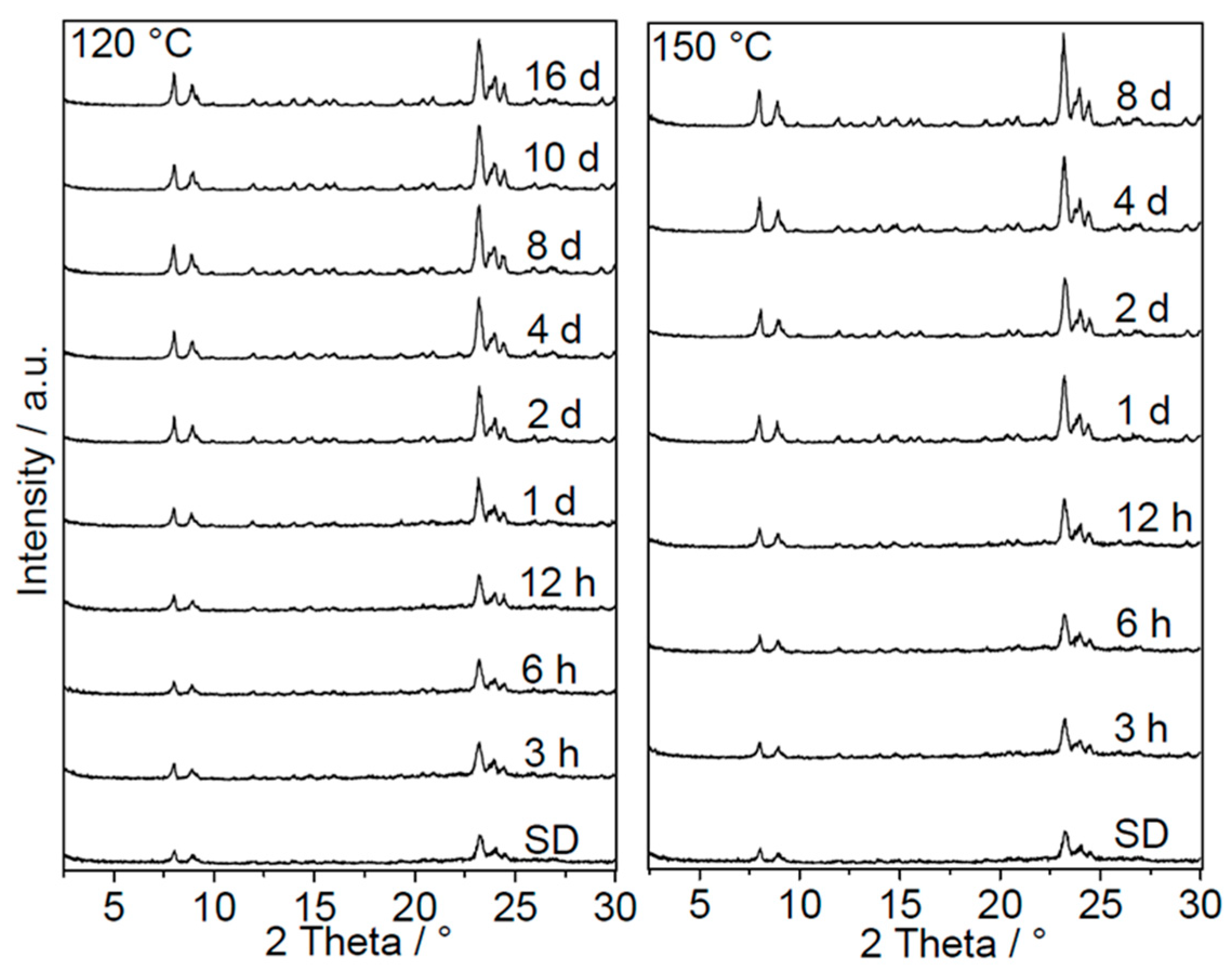
In the previous discussion, it was shown that hydrothermal synthesis results in low yield of nanosized zeolites, and spray drying can be used to recover and shape the solid phase from the synthesis mixture. The spray-dried particles are composed of nanosized ZSM-5 crystals, amorphous silica, and organic material. For the efficient utilization of the spray-dried nanosized zeolite particles, the amorphous silica should be transformed into zeolite as well. This was attempted by using the SAC method, as described in detail in the experimental section. Initially, SAC kinetic studies were conducted at 120 °C and 150 °C to follow the transformation of amorphous silica into MFI-type zeolites. All products collected after different SAC times were dried at 70 °C without any washing step. The dried powders were then directly characterized by using XRD, SEM, TEM and N2 sorption. In this way, no amorphous material was washed or removed from the sample, and the transformation process can be followed quantitatively.
The XRD results (
Figure 7) show that the intensities of MFI-type zeolite reflections increased with SAC time and reached a maximum after eight days. This indicates the continuous formation of new crystalline MFI material from amorphous silica as the SAC time increased. After a certain period of time, the amorphous silica was consumed completely, and only the sharp reflections corresponding to the MFI phase can be observed. The starting spray-dried powder had an apparent crystallinity of about 30% (
Figure 8). By heating this powder under steam conditions, the zeolite amount increased and reached a maximum at around 80% and 70% for SAC temperatures of 150 °C and 120 °C, respectively. A further increase in the synthesis time at a temperature of 120 °C resulted in slight decrease in the apparent crystallinity. From these observations, it can be concluded that the amorphous silica in the spray-dried samples can be successfully converted into MFI-type zeolite without any extra addition of the template prior to SAC.
Another aspect worth mentioning is the maximum crystallinity reached at each SAC temperature. In both cases, the maximum crystallinity reached was below 100%. For the SAC at 150 °C, a maximal crystallinity of about 80% was reached and no further gain with increasing synthesis time was observed. The crystallinities presented in
Figure 8 can be considered as apparent ones, since the powder analyzed directly after SAC still contained a high amount of organic material. Thus, true crystallinity was obtained only after the calcination of the samples or by considering the organic content in the as-synthesized samples. At this point, it can be assumed that all amorphous silica in the as-synthesized samples was successfully converted into the crystalline MFI phase. Later, the crystallinity of calcined samples will be discussed to further support this assumption. When the SAC temperature was reduced to 120 °C, anomalous behavior was observed. Independent of the synthesis time, the maximum crystallinity of the product formed at 120 °C was slightly lower than that synthesized at 150 °C. Usually, one would expect that both synthesis temperatures should give similar maximum crystallinities. This abnormality can be explained by diffusion limitations present during SAC at lower temperatures.
The transformation of amorphous silica into crystalline MFI material was also followed by ex situ SEM and TEM (
Figure 9). The images of the spray-dried precursor (
Figure 9a) show spherical particles with a broad particle size distribution. The individual spherical particles are composed of very small primary nanosized zeolite particles and amorphous silica. The amorphous phase is clearly visible on the TEM images. This is in good agreement with the XRD results presented in the previous discussion. All samples collected after different times of SAC retained a spherical morphology and a broad particle size distribution. This indicates that during the SAC process, the morphology of spherical aggregates from spray drying was fully preserved. The absence of any amorphous phases or large MFI crystals outside the spherical particles is remarkable. Upon increasing the SAC time, the amorphous silica phase starts to disappear, and the morphology of primary nanosized MFI phase start to change from spherical particles to edged crystals. In addition, the size of these primary particles started to increase. This indicates that, during the transformation process, the primary nanosized zeolites served as seeds or cores, on which a new MFI layer was formed. After an SAC time of about 8 days (192 h), no further amorphous silica phase was observed, and only edged crystals were present. This further supports the XRD results (
Figure 10), which showed the completion of the transformation after this time. A similar growth pathway has also been reported in the literature [
22].
To finally determine the true crystallinity and characterize the porosity of products collected after different steps, all samples were calcined as reported in the experimental section. A summary of their preparation path is also given in
Table 2. It was assumed that the washed sample only contains pure nanosized zeolites and, thus, was used as a standard to estimate the crystallinities, as described in
Section 3.2.
The diffraction patterns of products collected after different steps confirms the importance of the SAC step (
Figure 10A). Compared to the washed sample, the diffraction patterns of all dried samples show very low intensities. This confirms the low zeolite content in these samples. After the SAC of the spray-dried sample, an increase in intensity is observed. This is even higher than that of the washed sample. Thus, it can be concluded that the spray-dried particles contained a sufficient amount of alkalinity and organic material to convert all amorphous material into the MFI phase without any extra addition of TPAOH.
The SEM images of these samples (shown in
Figure 10B) further corroborate the above results. The dried sample contained nanosized zeolites particles embedded in poorly ordered amorphous silica phase. This amorphous phase shows a large amount of starting material, which is usually disposed after hydrothermal synthesis. When the nanosized zeolites were separated and washed, small spheres with diameters between 40 and 120 nm were collected. However, the total weight of the collected solid product was much lower than that from the dried or spray-dried samples. The difference in weight is due to the large amount of amorphous silica that was washed out and disposed after the hydrothermal synthesis. After spray drying, spherical particles composed of a mixture of nanosized zeolites and amorphous silica were obtained. After SAC, the amorphous silica disappeared completely, and only zeolite crystals were observed. Thus, a combination of spray drying and steam-assisted crystallization provides one of the best ways to overcome the technical problems associated with the separation and handling of nanosized zeolites, as well as the maximization of their yields.
Finally, the textural properties of the samples collected after different SAC times were determined. The spray-dried sample exhibited a high BET area and micropore volume (
Table 3). The high specific BET area can be explained by the mesopores enclosed in the amorphous silica phase contained in this sample. Owing to the amorphous nature of the silica phase, the pore sizes of the spray-dried particles were very broad, consisting of both large micropores and small mesopores. These large micropores and small mesopores resulted in the high micropore volume of this sample. After SAC, the specific surface area decreased due to the transformation of the amorphous silica phase into the zeolite. The micropore volume initially decreased and then started to increase until the theoretical value of 0.18 cm
3/g for pure microporous MFI-type zeolite was reached. In addition to this microporosity, additional interparticle mesopores were observed due to packing of the nanozeolites. The sorption results further confirm the above-described results from the SAC kinetics and highlight the importance of SAC in this work and in the sustainable preparation of nanosized zeolites.
3. Materials and Methods
3.1. Materials Used
Tetraethyl orthosilicate (TEOS, Alfar Aesar, 98%) as a silica source, Tetrapropyl ammonium hydroxide solution (TPAOH, Clariant Germany GmbH, Frankfurt, Germany, 40 wt.% technical grade) as template, Aluminum sulfate octadecahydrate (Al2(SO4)3.18 H2O. Merck, pure, Darmstadt, Germany), deionized water.
3.2. Preparation of Nanosized ZSM-5
Nanosized ZSM-5 were prepared by using a modified procedure of Persson et al. [
13]. The modification mainly involved omitting the addition of sodium. To prepare nanosized zeolites with a Si/Al ratio of 100 for kinetic and aging studies, 75 wt.% of the required water were weighed in a 500 mL polypropylene bottle. Then, three-quarters of the total amount of TPAOH solution was added to this bottle and the resulting mixture was agitated by using an overhead stirrer to form a homogeneous solution. To this solution, TEOS was added dropwise to form mixture 1. In parallel, mixture 2 was prepared by stirring the remaining deionized water, remaining TPAOH solution and alumina source in a separate beaker by using a magnetic stirrer. After 24 h of stirring at room temperature, mixture 2 was added dropwise to mixture 1 under agitation at room temperature to form a colloidal solution (also designated in this work as starting gel) with a molar composition of 1 SiO
2: 0.181 TPA
20: 19 H
2O: 4 EtOH: 0.0050 Al
2O
3. The resulting mixture was aged further at room temperature under stirring for a given time. The aging time is the time between the addition of mixture 2 to mixture 1 and transfer of the autoclaves into the oven. This aging time was varied between 1 and 96 h. After the aging step, a small sample was taken and dried at 90 °C. The remaining solution was distributed in different autoclaves. In this work, PTFE-lined stainless-steel autoclaves from Parr instruments (Deutschland) GmbH with volumes of 45 mL and 125 mL were used. After closing, the autoclaves were placed in an oven and crystallized at 100 °C under static conditions for a given synthesis time. The synthesis time was varied between 2.5 h and 48 h. After elapse of the planned synthesis time, the autoclaves were cooled by using cold water and the obtained milky suspension was divided into two portions. One portion was separated via centrifugation and washed three times to remove excess template, unconverted SiO
2 and Al
2O
3 and to neutralize the excess alkalinity. The remaining portion was dried at 90 °C without any purification or washing. Thereafter, all products were characterized and calcined to remove the organic materials.
3.3. Scale up and Preparation of Nanosized ZSM-5 with Different Si/Al Ratios
For scale up experiments, three synthesis gels with Si/Al ratios of 50, 100 and 200 were prepared as described in
Section 3.2. The total amount of the gel was scaled up to 1.5 kg and the amount of alumina source was varied accordingly. The aging time was 1 h and the crystallization was conducted in a 2 L autoclave equipped with a propeller for intensive agitation, thermocouples for in situ monitoring of synthesis temperature and pressure sensors for pressure monitoring. The heating was achieved by using an electrical heating jacket. The synthesis was conducted at 100 °C for 22 h. After the synthesis, only a small part of the suspension was collected and washed three times via centrifugation and dried at 75 °C overnight. This product was used as standard for calculating the crystallinity. Another small part of the suspension was dried at 90 °C in a conventional oven for 16 h. This product has been designated as the dried sample. The remaining suspension was spray dried as described by Klumpp et al. [
21], and the resulting product was used for the subsequent step.
3.4. Steam-Assisted Crystallization of Spray-Dried Granulates
After spray drying, the collected granules were directly converted by steam-assisted crystallization (SAC). The SAC was performed in PTFE-lined stainless-steel autoclaves with a total volume of 22 mL. Typically, about 0.25 g of spray-dried powder was loaded into a PTFE crucible. The crucible with the spray-dried particles was then placed on top of a PTFE holder inside a Teflon liner, containing about 0.5 g of water. The whole assembly was designed to avoid any direct contact between water and the spray-dried powder. Finally, the Teflon liner was placed in the autoclave and the sealed autoclave was heated in an oven for a given synthesis time at a preselected temperature. The temperature was fixed to either 150 or 120 °C. The synthesis time was varied between 3 h and 16 days. After this time, the collected, almost dried, solid product was further dried at 75 °C overnight without any washing. If necessary, part of the dried solid was calcined. All spray-dried samples were characterized by using a variety of methods.
3.5. Characterization of Different Materials
Different dried, washed and spray-dried products were characterized by using X-ray diffraction (XRD), scanning electron microscopy (SEM), thermogravimetric analysis (TGA), N2 sorption and inductively coupled plasma optical emission spectrometry (ICP-OES).
XRD measurements were performed using a Philips diffractometer equipped with a Cu-Kα X-ray tube (40 kV, 40 mA). The resulting diffraction patterns were used for phase identification and calculating the MFI crystallinity.
The crystallinity was calculated by comparing the areas under the reflections between 2 theta of 23 and 25° of the sample under investigation to that of a standard sample. The samples were studied in three different forms, viz. in dried form, spray-dried form before and after SAC, as well as in calcined form. The dried form was obtained after drying the suspension collected from hydrothermal synthesis at 90 °C under static conditions. Samples from both states contained zeolite, amorphous material, and the template. To calculate the zeolite content in these samples, their diffraction patterns were compared with that of a standard sample. The standard used was the solid product collected from the same batch of hydrothermal synthesis after centrifugation, washing and drying. The assumption is that after washing, the standard contains only the zeolite phase, and is thus 100% crystalline. By comparing the areas under selected reflections in the diffraction patterns of the sample under investigation with that of the standard, the crystallinity and the amount of zeolite in the sample were estimated. In this way, the relative structural changes induced by different treatments of the samples were quantified. One problem with this method is in the analysis of as-synthesized samples. These samples still contain organic material used as template during zeolite formation. Therefore, the crystallinity calculated for the samples before calcination will be regarded as apparent one. Only after calcination are true crystallinities obtained.
SEM was performed without any sample pre-treatment using a Carl Zeiss ULTRA 55 microscope at a voltage of 3 kV.
TGA was performed by heating the sample from room temperature to 100 °C with a ramp of 10 °C/min. After holding this temperature for 30 min, the sample was further heated to 800 °C with the same ramp under air flow of about 120 mL/min. All measurements were performed by using a SDT2960 from TA Instruments.
N2 sorption measurements were performed using a Quadrasorb SI from Quantachrome. Before measurement, the samples were dehydrated at 250 °C under vacuum for 12 h. The specific surface area was analyzed by applying the BET model at relative pressures below 0.2. The micropore volume was determined by using the t-plot method, whereas the total pore volume was calculated at a relative pressure of 0.99.
4. Conclusions
Although nanosized zeolites are interesting future catalytic materials, their preparation via hydrothermal synthesis is limited by the low yield and large amounts of waste produced. The current work has utilized the combination of spray drying and steam-assisted crystallization to improve the efficiency of the hydrothermal synthesis of aluminum-containing nanosized MFI type zeolites. It has been shown that the yield of nanosized zeolites from hydrothermal synthesis depends on the Si/Al ratio of the starting gel. Whereas for a Si/Al ratio of 200, yields of over 80% were obtained, yields were no more than 45% for Si/Al ratios below 100. Attempts to increase this yield via aging prior to hydrothermal synthesis led only to minor improvements. In this work, a sequence of post-synthetic techniques was used to simplify the recovery of nanoparticles, fully convert all starting materials into crystalline MFI-type zeolites with nanosized dimensions and to reduce the amount of waste produced.
After hydrothermal synthesis, spray drying was used to overcome the problems associated with the recovery and handling of nanosized zeolites. The resulting spherical particles can be easily handled by common techniques like filtration. However, these particles contained more than 50% of amorphous material. Another problem of spray drying is the excessive decomposition of the template, which is needed for the subsequent transformation of amorphous material into a crystalline zeolite phase. Usually because of this excessive template decomposition, more template needs to be additionally added to enable the full conversion of the amorphous material. The addition of the template is expensive and should be avoided.
The current work has shown that any attempts to dry the suspension from hydrothermal synthesis resulted in the loss of up to 50% of the template. Nevertheless, by careful controlling the spray drying temperature, it was possible to minimize the excessive destruction of the template. Thus, the extra addition of the template could be omitted. Spray drying temperatures between 300 and 400 °C produced particles with sufficient amount of the template and low amount of water. The products spray-dried at these moderate temperatures could be successful transformed into MFI-type zeolites via SAC without extra addition of the template.
From the kinetics of SAC, it is evident that four to eight days were needed to transform the amorphous material into crystalline MFI material. During SAC, no excessive dissolution of silica was observed, and the spherical morphology of the spray-dried particles was preserved. The transformation started and proceeded around the nanosized crystals contained in the spray-dried particles. It is assumed that the nanosized zeolite crystals acted as seeds. At the end of SAC, the transformed amorphous phase formed a thin MFI shell on the surface of nanosized particles and no amorphous phase was detected. Thus, the amorphous phase from hydrothermal synthesis was completely converted via SAC into a zeolite phase. The advantage of this approach is that full conversion of the starting raw material can be achieved by using standard techniques, which could also be realized on a technical scale.

 ,
, 


