Article

Construction of NiFe-Layered Double Hydroxides Arrays as Robust Electrocatalyst for Oxygen Evolution Reaction

1
College of Chemistry and Material Engineering, Guiyang University, Guiyang 550005, China
2
The Key Lab of Low-Carbon Chem & Energy Conservation of Guangdong Province, School of Chemistry, Sun Yat-Sen University, Guangzhou 510275, China
*
Authors to whom correspondence should be addressed.
Catalysts 2023, 13(3), 586; https://doi.org/10.3390/catal13030586
Submission received: 12 February 2023 / Revised: 10 March 2023 / Accepted: 11 March 2023 / Published: 14 March 2023
(This article belongs to the Special Issue Recent Advances in Energy-Related Materials in Catalysts)

Abstract

:
Electrochemical water splitting is considered to be an important method for efficient hydrogen production to alleviate energy shortage and environmental pollution, but its development is currently limited by the slow oxygen evolution reaction (OER). To solve the sluggish reaction kinetics of OER, the focus is on the exploration of low-cost and efficient electrocatalysts, which is quite significant for the development of electrochemical water splitting. Herein, a NiFe layered double hydroxides (LDH) electrocatalyst (denoted as FNH) is achieved by a simple one-step hydrothermal method. The experimental results show that due to the synergistic interaction of introduced Fe species, the FNH possesses a special three-dimensional (3D) vertical nanosheet array structure, which results in efficient ion access. More importantly, the strong electronic interaction between Fe and Ni sites results in the optimized electronic structure of the Ni sites, which not only generates abundant Ni3+ sites as optimized active sites for OER, but also decrease the charge transfer resistance. Thus, the FNH catalyst exhibits an extraordinary overpotential of 386.8 mV to deliver 100 mA cm−2, showing better activity than that of RuO2, and satisfactory cycling stability after continuous operation for 28 h. Our work provides an easy-to-implement method to obtain high-efficiency OER electrocatalysts.

1. Introduction

The boom in the growing serious energy requirements and environmental problems in daily life has stimulated a growing demand for safe, environmentally friendly and economical energy resources as alternative to fossil fuels [1,2,3]. Compared to other renewable-but-intermittent energy (such as solar and wind energy), hydrogen (H2) has attracted extensive scientific and technical interest as a potential energy substitute, such as the application of hydrogen metallurgy and hydrogen fuel cell. This should be ascribed to its unique advantages of the continuous energy supply, no toxic or harmful byproducts and high energy density (142 MJ kg–1) [4]. There are many technologies for hydrogen production, including water splitting, fossil fuel cracking and water-gas shift reaction. Among all these methods, the electrochemical water splitting is envisaged as one of the most efficient approaches for the sustainable production of clean and renewable hydrogen energy, which can alleviate the growing energy demand and environmental problems [5,6,7,8]. However, as one of the critical half-reactions of electrochemical water splitting, the oxygen evolution reaction (OER) involving a complex four-electron transfer mechanism, possesses sluggish kinetics and high overpotential (2H2O → O2 + 4H+ + 4e in acidic media and 4OH → O2 + 2H2O + 4e in alkaline media). OER is the main rate-limiting step that impedes the efficiency of water splitting [9,10]. Therefore, it is necessary to design highly effective OER catalysts to minimize energy barrier. To date, some noble metal oxides (such as IrO2 and RuO2) have been demonstrated to achieve high OER activities and stabilities [11,12]. Unfortunately, their large-scale application is restrained by the scarce and expensive materials. Recently, some noble metal-free catalysts with low cost, abundant reserves and comparable activities have been developed, such as transition metal-based oxides, (oxy)hydroxides, phosphates, chalcogenides, nitrides and other compounds [13,14,15,16,17,18]. Nevertheless, it is still significant to further optimize the catalytic performance through rational design of the microstructure and chemical composition of OER catalysts to adapt practical applications.
Layered double hydroxide (LDH) sees a bright future as an outstanding catalyst for OER due to its unique layered structure with high specific surface area and ion diffusion ability, as well as special electron distribution and high catalytic activity [19,20,21]. Its OER electrolysis is usually carried out in an alkaline electrolyte, and elementary steps can be described as follows: [M] + OH → [M-OH] + e; [M-OH] + OH → [M-O] + H2O + e; [M-O] + OH→[M-OOH] + e; [M-OOH] + OH → [M-OO] + H2O + e; [M-OO] → [M] + O2 [19,20]. LDH is a series of 2D anionic clay materials consisting of positively charged brucite-like layers, interlayered with the solvation molecules and the charge-compensating anions. Various metal cations are combined to form the positively charged layers, such as Fe, Mg, Cu, Co and Ni.
Among various LDH catalysts, NiFe LDH is generally accepted as one of the most promising OER catalyst in alkaline media [22]. Accordingly, intensive research efforts have been conducted to explore the catalytic mechanism and improve its performance by various strategies, including heteroatomic doping, composite with conductive materials, morphology control and vacancy engineering. For example, Van et al. introduced La3+ to NiFe LDH by a hydrothermal method [23]. The La3+ exhibited synergistic electronic interactions with Ni and Fe to form stronger Fe-O bonds based on the d-band theory, which was conducive to exposing more active sites and oxygen vacancies, thus improving OER performance. Similarly, Zhu et al. prepared a NiCoFe ternary LDHs by easily electrodeposition, which had the ability to form a superaerophobic surface to hinder the generation of large gas bubbles. At the same time, the introduction of Co element effectively improves the electrical conductivity of this NiCoFe ternary LDHs and further improves its intrinsic catalytic performance [24]. Duan et al. used the positively charged NiFe-LDH nanosheets and the negatively charged carbon nanotubes (CNTs) to synthesize a NiFe LDH/CNTs composite, whose unique intercalating heterostructure not only boosted electron transport, ion diffusion of OER and oxygen release, but also provided sufficient active sites to possess better OER activity [25]. Furthermore, a three-dimensional (3D) hierarchical NiFe-LDH modified with oxygen and iron vacancies was endowed with abundant coordinatively unsaturated sites to promote the adsorption of oxygenated intermediates, thus achieving enhanced OER activity [26]. Negatively charged defective graphene had also been tried to modify NiFe LDH catalysts [27]. The defective active sites on the graphene and the strong coupling between Ni and Fe contributed to the excellent OER performance. Despite these encouraging achievements, the relatively few active sites and weak ion access remain issues for NiFe LDH catalysts. Thus, the development of high-performance NiFe LDH catalysts adapted practical for applications is highly desired but still very challenging.
Herein, a NiFe LDH catalyst (denoted as FNH) is synthesized on Ni foam (denoted as NF) substrate via a facile hydrothermal method. This method not only enables FNH catalyst to be constructed in situ on substrate without binder, boosting electron transfer and maintaining stability, but also allows its uniform dispersion and vertical growth. Otherwise, compared with Ni(OH)2 (denoted as NH), the morphology and chemical composition of FNH can be modified by the appropriate addition of Fe element during the synthesis process. The special vertical nanosheet arrays and 3D self-supported configuration is designed to achieve high specific area and open-pore structure, thus facilitating ion access efficiency. More importantly, the synergistic interaction between Fe and Ni sites results in the electron deficiency of Ni sites, which produce abundant Ni3+ with a more suitable electronic configuration for OER than that of Ni2+ to increase the exposed active sites. Moreover, the interaction between Fe and Ni sites provides lower charge transfer resistance. Consequently, the FNH catalyst embeds outstanding OER performance with an overpotential of 386.8 mV to deliver 100 mA cm−2, together with good cycling stability after continuous operation for 28 h or CV scanning for 5000 cycles, substantially outperforming many recently reported OER electrocatalysts.

2. Results

As displayed in Figure 1, the FNH catalyst was synthesized by a simple one-step hydrothermal method. Specifically, NiCl2 and FeCl3 were first dissolved in deionized water, and then the solution was adjusted to pH = 10 using a mixture of NaOH and Na2CO3. Subsequently, the resultant precursor solution and cleaned NF substrate treated by ethyl alcohol, HCl and deionized water were moved to a Teflon-lined stainless steel autoclave, which was heated to 180 °C for 9 h. As a comparison, the NH catalyst was fabricated by the same method without FeCl3 modifier.
The microstructure and chemical composition of both NH and FNH catalysts were investigated. As revealed by scanning electron microscopy (SEM), a layer of irregular nanoparticles grows closely covered on the surface of the NF substrate for NH catalyst (Figure 2a), while the FNH catalyst demonstrates an aligned nanosheet array grown uniformly onto NF substrate. It is beneficial to realize a long-range ordered porous framework, which can ensure the satisfactory contact between electrolyte and catalyst, thus facilitating ion diffusion during OER process (Figure 2b). Energy-dispersive X-ray spectroscopy (EDS) mapping results show that only Ni and O elements are detected at the NH, while the Ni, Fe and O elements are uniformly distributed in the FNH for comparison. Furthermore, transmission electron microscopy (TEM) image clearly confirms the nanosheets structure for FNH catalyst with the thickness ranging from 3 to 4 nm (Figure 2c). Its high-resolution transmission electron microscopy (HRTEM) image presents a lattice spacing of 0.27 and 0.25 nm, which corresponds to the (101) and (012) crystal planes of NiFe LDH, respectively (Figure 2d). Moreover, the SAED pattern detects the ordered bright diffraction spots, which fits the (101), (012), (113) and (119) crystal plane of NiFe LDH, respectively, as shown in Figure 2e. Figure S1 displays the X-ray diffraction (XRD) patterns of FNH and NH catalysts on NF substrate, which only show the three typical diffraction peaks at 44.5°, 51.8° and 76.4° assigned to the (111), (200) and (220) crystalline planes of Ni (JCPDS No. 87-0712) [28]. No other peaks are observed due to low content of NH and FNH active materials (about 1.58 mg cm−2) compared to the NF substrate. Therefore, two catalyst powders were collected for characterization to eliminate substrate interference (Figure 2f). All the diffraction peaks of the NH catalyst are well consistent with Ni(OH)2 (JCPDS No. 14-0117), such as (001) crystalline planes at 19.3°, (100) crystalline planes at 33.1°, (101) crystalline planes at 38.5° and (102) crystalline planes at 52.1° [29]. For FNH catalyst, all the diffraction peaks are well matched with NiFe LDH (JCPDS No. 40-0215), such as (003) crystalline planes at 11.5°, (006) crystalline planes at 23.0°, (101) crystalline planes at 33.5° and (012) crystalline planes at 34.4°, respectively, which is consistent with the above results [30]. In particular, the FNH catalyst possesses the typical interlayer peak of (003) crystalline plane at 11.5°, proving the interlayer distance of 0.76 nm, which further indicates that the NiFe LDH material are successfully grown on the NF substrate [31,32].
X-ray photoelectron spectroscopy (XPS) measurements were carried out to identify the superficial electronic states of FNH and NH catalysts. The XPS survey spectra of NH on NF substrate confirm the presence of Ni, O and C elements without other impurity peaks (Figure S2a). The existence of C element is due to the adsorption of adventitious organic small molecules in the air. Meanwhile, a weak peak near 725.0 eV is detected in the Fe 2p-Ni LM spectrum of FNH, which corresponds to Fe 2p1/2 (Figure S2b). However, it is difficult to concretely analyze the electronic state of Fe element in FNH catalyst due to the strong auger peaks of Ni element (Ni LM) from the NF substrate. Therefore, we also characterized two catalyst powder samples. Consistent with the previous results, Ni, O and C elements coexist in NH and FNH powders (Figure 3a). Meanwhile, the presence of Fe element can be clearly detected in FNH catalyst (Figure 3b), which presents two dominant peaks at 712.4 and 725.0 eV along with two broad satellite (identified as “Sat.”) peaks at 719.4 and 734.3 eV, corresponding to Fe 2p3/2 and Fe 2p1/2, respectively. They can be deconvoluted into two peaks assigned to Fe2+ and Fe3+ [33,34]. Furthermore, according to the peak-fitting analysis of Ni 2p spectra, the additional introduction of Fe element is also accompanied by the valence state variation of Ni. Specifically, two states of Ni element, while can be deconvoluted into four peaks assigned to the Ni2+ 2p3/2 and Ni2+ 2p1/2 at 855.3 and 872.9 eV, and Ni3+ 2p3/2 and Ni3+ 2p1/2 at 856.6 and 874.6 eV, respectively, exist in both FNH and NH catalysts, but the percentage of Ni3+ (43.7%) in FNH catalyst is significantly higher than that of NH catalyst (35.1%) (Figure 3c) [35,36]. This change can be identified in terms of the valence electron structures of Ni and Fe ions. For NH, the t2g of Ni2+ sites are fully occupied and thus interact with bridging O2− by e-e repulsion, which hinders the charge transfer. In contrast, the introduced Fe3+ sites have three unpaired electrons in the t2g, implying that they interplay with the bridging O2− by π-donation. In this case, partial electron transfer from Ni2+ to Fe3+, due to the stronger π-donation of Fe-O than e-e repulsion of Ni-O, resulting in the electron deficiency of Ni sites in the FNH catalyst [16,26]. Crucially, the electronic configuration of Ni3+ sites (t2g6eg1) tend to form σ-bonds with the oxygen-related adsorbate during OER process compared with Ni2+ sites, elevating the electron transfer between surface metal ion and reaction intermediate, which is favorable for OER activity of FNH catalyst [37,38]. Moreover, the deconvolution of O 1 s spectra in Figure 3d shows the three peaks at 529.4, 530.8 and 532.1 eV, which are attributed to metal-O, metal-OH and surface-adsorbed H2O (H-O-H), respectively, further confirming the chemical composition of FNH and NH catalysts [39].
The OER performance of NH and FNH electrocatalysts was evaluated using a typical three-electrode system in 1 M KOH solution, where Hg/HgO and carbon rod electrodes were used as reference electrode and counter electrode, respectively. Figure 4a shows the linear sweep voltammetry (LSV) polarization curves at the scan rate of 5 mV s−1 of NH and FNH electrocatalysts, along with that of the commercial RuO2 and pure NF substrate catalysts as a reference to compare. The FNH catalyst exhibits lowest OER overpotentials of 325.8, 386.8, 493.8 mV to achieve the current densities of 50, 100 and 200 mA cm−2, respectively (Figure 4b), indicating the better catalytic activity of FNH catalyst than that of NH catalyst, which possesses a higher OER overpotentials of 436.8, 524.8, 670.8 mV at current density of 50, 100, 200 mA cm−2, as well as that of noble metal RuO2 and NF substrate. Meanwhile, the corresponding Tafel slope of 136.2 mV dec−1 for the FNH catalyst also is much smaller than that of the NH (186.5 mV dec−1), RuO2 (162.0 mV dec−1) and NF (280.1 mV dec−1) catalysts (Figure 4c). The LSV polarization curves corrected with iR-correction also exhibit the same results (Figure S3). More importantly, the OER performance of the FNH electrocatalyst also outstrips many recently reported OER catalysts (Figure 4d), such as NiCoFe LDH catalyst (395 mV), FeNi3N-NPs catalyst (~388 mV), NiCoP/C catalyst (449 mV), NiMo2C (1:2)-NCNFs catalyst (432 mV), NiS/NiS2/NF catalyst (416 mV) and NM50-Ni3S4 (400 mV) [40,41,42,43,44,45].
To explore the general principle of optimized OER activity of FNH, the Nyquist plots of electrochemical impendence spectroscopy (EIS) of FNH and NH catalysts were measured and fitted with an equivalent circuit (Figure S4). As shown in Figure 4e and Figure S5, the charge-transfer resistance (Rct) of FNH catalyst (3.2, 1.3, 0.86 and 0.68 Ω) is always lower than that of NH catalyst (5.5, 1.9, 1.1 and 0.87 Ω) at different applied potentials, including 1.53, 1.58, 1.63 and 1.68 V vs. relative hydrogen electrode (RHE). These results indicate that the strong electronic interaction between Fe and Ni in FNH decrease the charge transfer resistance during OER courses [25,26]. Meanwhile, the electrochemical active surface area (ECSA) was investigated by the double-layer capacitance (Cdl), which was obtained by testing a series of cyclic voltammetry (CV) curves with different scan rates (20, 40, 60, 80 and 100 mV s−1) in Faradaic potential range (0.93–1.03 V vs. RHE) (Figure S6). As shown in Figure 4e, The FNH catalyst delivers a larger Cdl value of 1.0 mF cm−2 than that of NH catalyst (0.74 mF cm−2), implying the more exposed active sites of FNH catalyst after the appropriate addition of Fe element, which can respond to the OER process. In addition, the ECSA of FNH and NH catalysts were calculated to be 12.5 and 9.25 cm−2, respectively. Based on their ECSA value, LSV curves showing the current density normalized by ECSA value are then obtained to further highlight the intrinsic catalytic activity as shown in Figure S7. It can be clearly shown that the FNH catalyst exhibits better activity than NH catalyst even after normalization with ECSA value.
Long-term stability is a key index for evaluating performance of the OER catalysts. More encouragingly, as shown in Figure 5a, the FNH electrocatalyst also shows good stability, where it displays 127.3% of the original performance after OER by applying a constant potential of 1.63 V for ~28 h. The increasing performance can be ascribed to the gradual stabilization of the electrolyte penetration to the surface and interspace of catalysts during the test, which advance the ion diffusion at the electrode-electrolyte interface, as well as the probable electrochemical activation of the FNH catalyst (due to the limitation of workstation test time, it was retested at 14 h, where the current pulsated). In comparison, the performance of NH catalyst is only maintained at 74.9%. The LSV polarization curves in the initial state and after the reaction are also consistent. The OER overpotential of NH increases by 12 mV after test in Figure 5b, while that of FNH decreases by 36 mV in Figure 5c to achieve the current density of 100 mA cm−2. Moreover, the characterization of FNH catalyst after OER test was investigated. The SEM image of FNH catalyst after continuous operation for 28 h still shows an aligned nanosheet array, which is not significantly different from that before the OER test (Figure S8), and the Fe 2p-Ni LM and Ni 2p spectra of FNH catalyst after OER test are similar to those before the OER test (Figure S9). At the same time, the stability of FNH electrocatalyst was further studied by continuous CV scanning in the range of 0.93–1.63 V vs. RHE for 5000 cycles at a scan rate of 100 mV s−1. Figure 5d shows the LSV curves of FNH before and after test, whose morphology are nearly unchanged and overlapped, suggesting its robust OER stability.

3. Materials and Methods

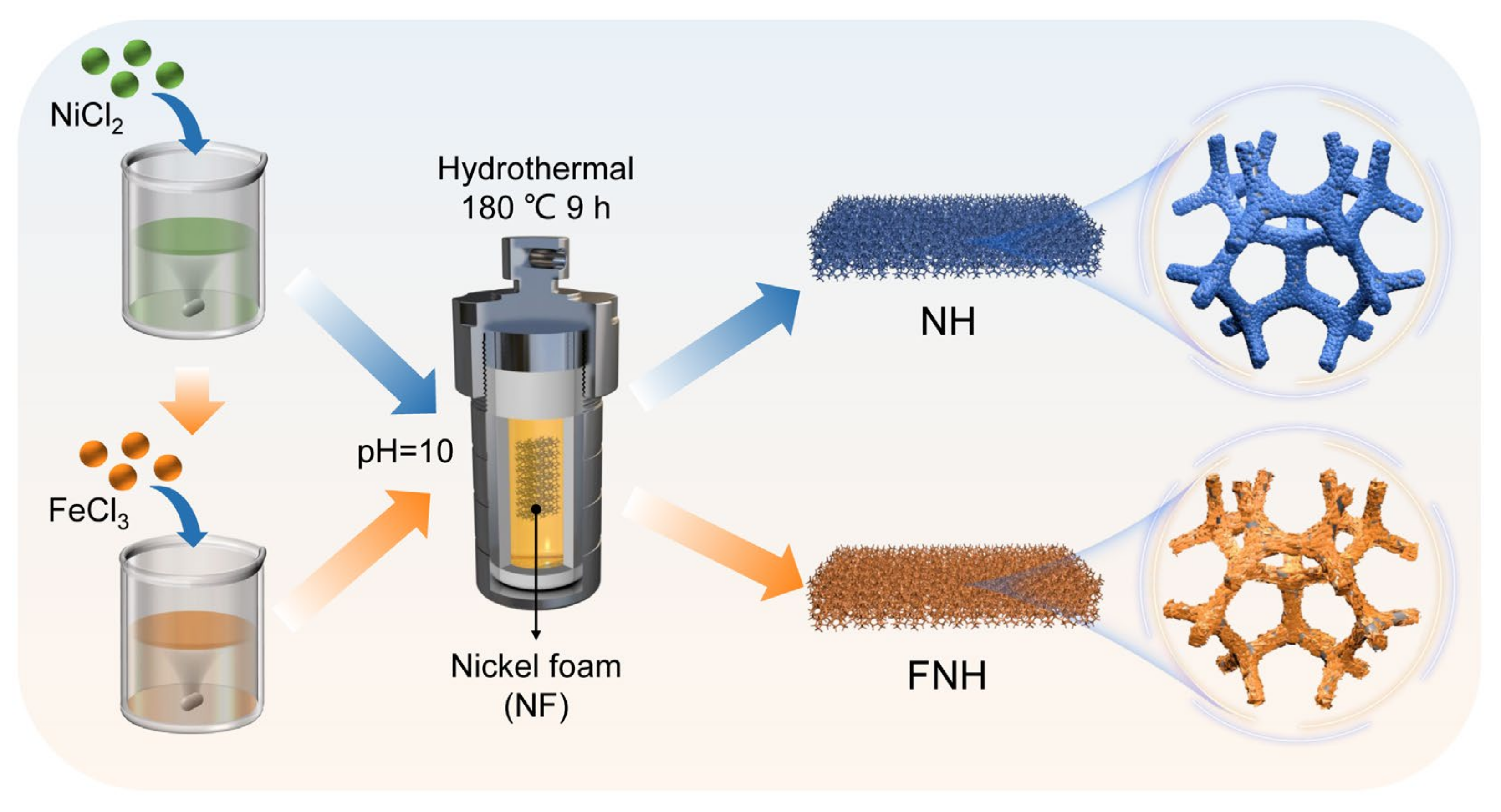
3.1. Synthesis of NH and FNH Catalysts

All the chemicals were directly used as purchased without further purification. The FNH catalyst was synthesized by a one-step hydrothermal method. First, the reaction solution was prepared by dissolving 2.28 g nickel chloride hexahydrate (NiCl2·6H2O, Heowns, Tianjin, China, N-27462+500g) and 0.89 g ferric chloride hexahydrate (FeCl3·6H2O, Maclin, Shanghai, China, I809489-500g) into 60 mL deionized water, and then this solution was adjusted to pH = 10 by a mixed solution of 2.25 M sodium hydroxide (NaOH, Guangzhou, China, GSBD27-AR-500G) and 1.50 M sodium carbonate (Na2CO3, Guangzhou, GS0239). Subsequently, 20 mL of the precursor solution was transferred to a 25 mL Teflon-lined stainless steel autoclave with the treated Ni foam substrate (NF, 2 × 3 cm) and heated at 180 °C for 9 h. NF substrate was immersed beforehand into ethyl alcohol, 3 M hydrochloric acid (HCl, Guangzhou, China, ZXI780) and deionized water for 10 min for ultrasonic cleaning, successively. The NF was freshly washed. After the reaction, the as-prepared FNH catalyst was washed with deionized water and dried overnight at 60 °C. At the same time, the powder sample in the reaction solution were centrifuged and washed with deionized water for characterization. The fabricated process of the NH catalyst was similar with that of FNH catalyst without adding the FeCl3·6H2O. The mass loading of FNH catalyst (1.58 mg cm−2) was measured by electronic scales (BT25S, 0.01 mg), and the mass loading of NH catalyst is similar.

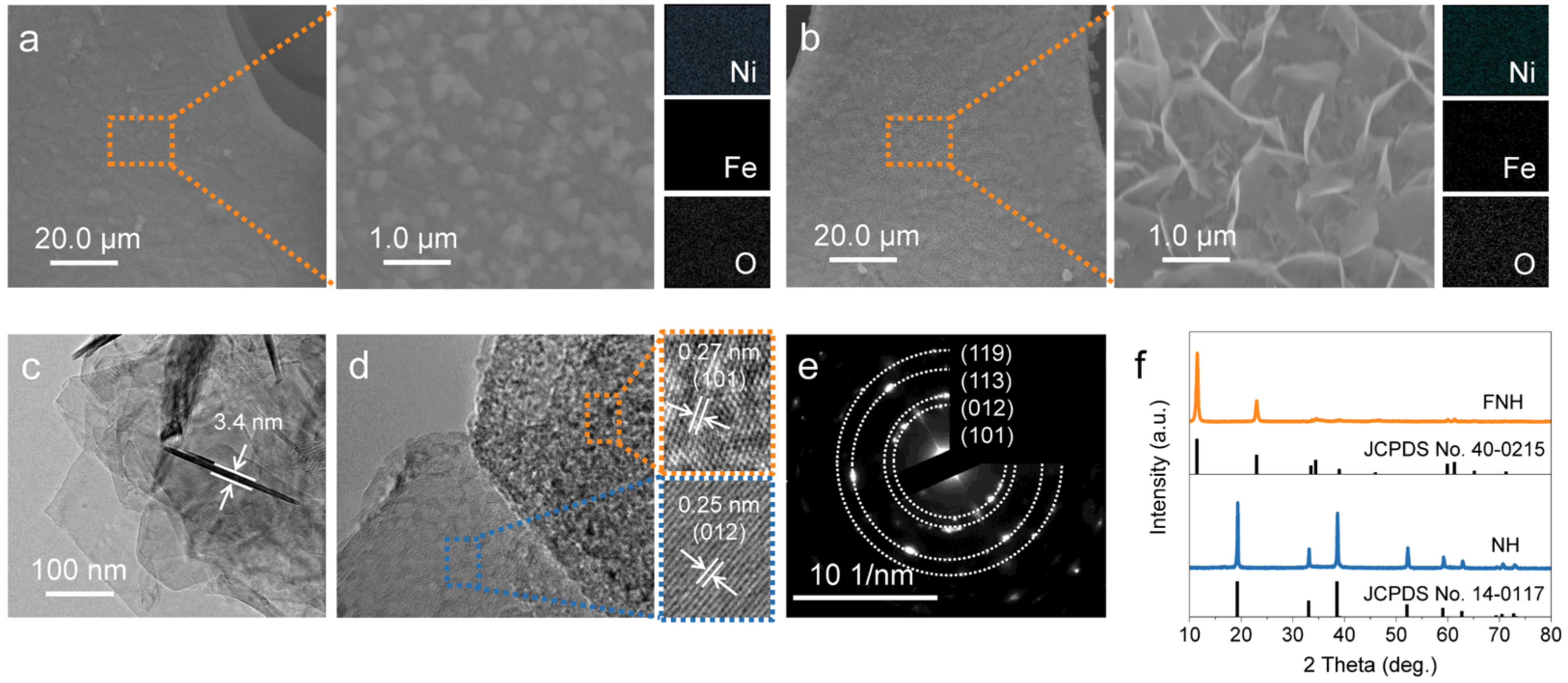
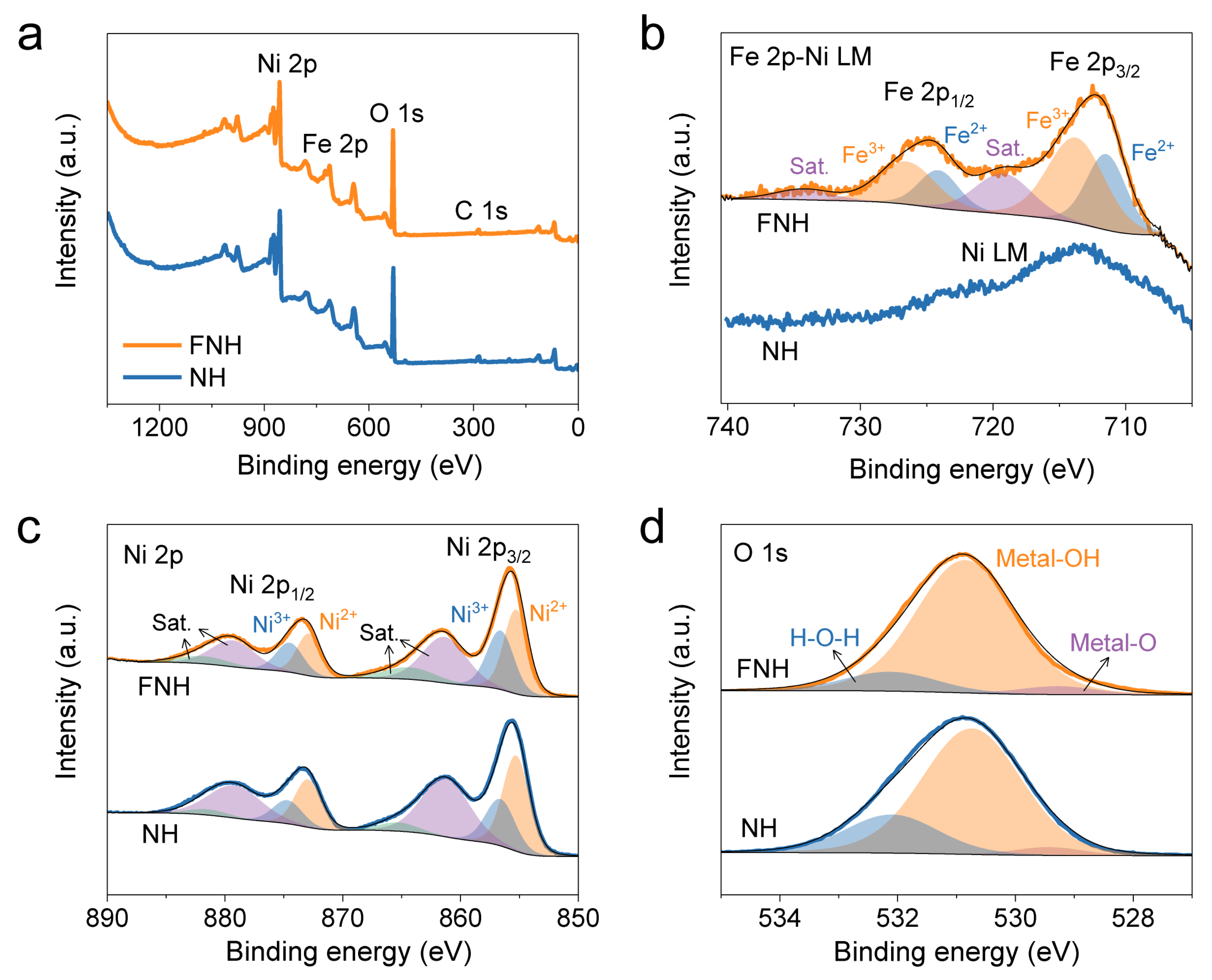
3.2. Materials Characterization

The morphology and structure of NH and FNH catalysts were characterized by scanning electron microscopy (SEM, JSM-6330F, JEOL, Tokyo, Japan) coupled with energy dispersive X-ray spectroscopy (EDS) mapping and transmission electron microscopy (TEM, Tecnai G2 F30, FEI, Hillsboro, OR, USA). And the chemical composition of NH and FNH catalysts was measured through X-ray diffraction (XRD, D-MAX 2200 VPC, RIGAKU, Tokyo, Japan) and X-ray photoelectron spectroscopy (XPS, ESCALab250, Thermo Scientific, Waltham, MA, USA). The XRD were taken by Cu X-ray Kα radiation at 10° min−1, and the parameters were set at 40 kV and 26 mA. The XPS were taken by Al X-ray Kα radiation, and energy calibration of the data was performed based on the hydrocarbon C 1s peak (284.8 eV) after the test. The pH was tested by the portable pH-meter (pH5 pen-based pH tester, SANXIN, Shanghai, China).

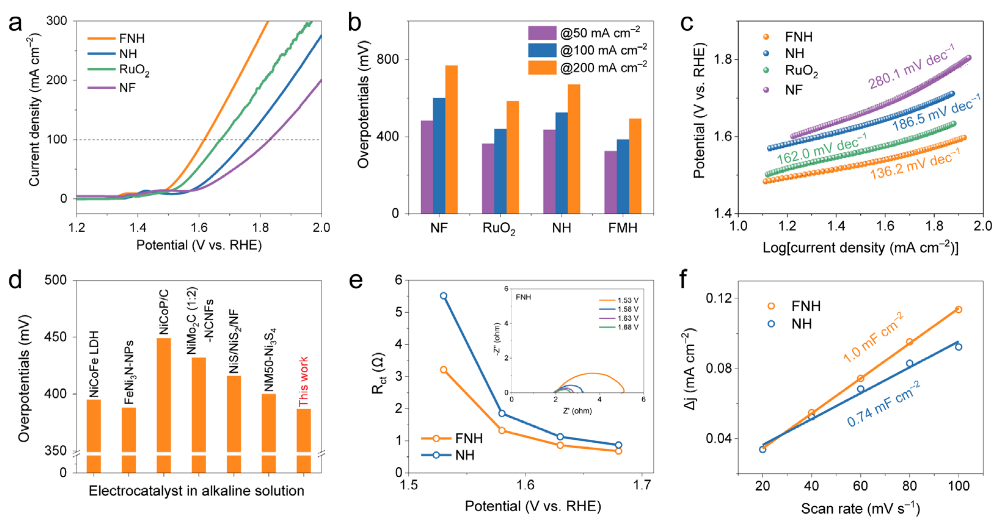
3.3. Electrochemical Measurements

The electrochemical data were collected by employing electrochemical workstation (CHI 760E) at room temperature. The electrochemical performance of NH and FNH catalysts were performed in a three-electrode system, in which Hg/HgO electrode, catalysts and carbon rod were the reference electrode, working electrode and counter electrode, respectively. The relation between the Hg/HgO reference and reversible hydrogen electrode (RHE) in 1 M KOH solution can be established using the Nernst equation:
E RHE = E Hg / HgO + 0.059 × pH + 0.098
For OER performance testing, the linear sweep voltammetry (LSV) measurements were collected at a scan rate of 5 mV s−1. The cyclic voltammetry (CV) curves were collected in the range of 0.93–1.63 V versus relative hyedrogen electrode (RHE) at a scan rate of 100 mV s−1 to get the stability test. Moreover, successive amperometry i-t curves were obtained by applying a constant potential of 1.63 V to evaluate the electrochemical stability. Electrochemical impedance spectroscopy (EIS) was performed at different applied potentials ranging from 100 kHz to 0.01 Hz and the electrodes were left to stand for 15 min before the test to stabilize the potential. The CV curves also were collected in the range of 0.93–1.03 V versus RHE at various scan rates from 20 to 100 mV s−1 to stand for the effective electrochemical active surface area (ECSA). The ECSA was calculated using the equation:
ECSA = C dl / C s × A geo
where Cdl (mF cm−2) is the double-layer capacitances value, Cs (typical 0.04 mF cm−2) is the specific capacitance, and Ageo (0.5 cm2) is the geometric surface area of the catalyst electrodes.

4. Conclusions

In summary, we have demonstrated a simple one-step hydrothermal method for constructing a robust FNH electrocatalyst on NF substrate. The as-prepared FNH catalyst delivers a lower overpotentials of 386.8 mV to deliver 100 mA cm−2 than that of NH and RuO2 catalysts, and FNH catalyst also has achieved a good cycling stability after continuous operation for 28 h and CV scanning for 5000 cycles. It can be ascribed to the following two factors according to the characterization and experimental results: (i) the special vertical nanosheet arrays and 3D self-supported substrate with high specific area and open-pore structure; (ii) the introduction of Fe element and the accompanying regulation in electronic structure of Ni element due to the iron-induced electron redistribution. These advantageous properties render the FNH catalyst with high efficiency of ion access, abundant catalytically active sites and reduced charge transfer resistance, thereby promoting OER performance. The FNH catalyst possesses better OER performance with an overpotential of 386.8 mV to deliver 100 mA cm−2 than RuO2 and NH catalysts, together with good cycling stability after continuous operation for 28 h or CV scanning for 5000 cycles. Our findings provide enlightening insights for design of high-performance LDH-based electrocatalyst for OER.

Supplementary Materials

The following supporting information can be downloaded at: https://www.mdpi.com/article/10.3390/catal13030586/s1, Figure S1: XRD patterns NH and FNH catalyst on NF substrate; Figure S2: (a) XPS survey spectra and (b) Fe 2p-Ni LM spectra of NH and FNH on NF substrate; Figure S3: LSV polarization curves at 5 mV s−1 with iR-correction of the as-prepared catalysts; Figure S4: The equivalent circuit for modeling the measured electrochemical response; Figure S5: Nyquist plots of NH at different applied potentials; Figure S6: The CV curves of NH and FNH at the scan rates of 20–100 mV s−1; Figure S7: The ECSA-corrected LSV curves of NH and FNH catalysts; Figure S8: SEM images of FNH catalyst after continuous operation for 28 h; Figure S9: (a) Fe 2p-Ni LM and (b) Ni 2p spectra of FNH catalyst before and after continuous operation for 28 h.

Author Contributions

Conceptualization, X.L. and Y.W.; methodology, X.L.; validation, Y.W.; investigation, Q.L.; writing—original draft preparation, Q.L.; writing—review and editing, X.L. and Y.W.; supervision, X.L. All authors have read and agreed to the published version of the manuscript.

Funding

This research was funded by National Natural Science Foundation of China (22269003), The central government guides local science and technology development funds ([2022]4053), and Project of Guizhou Provincial Department of Education ([2022]056).

Data Availability Statement

Data is contained within the article.

Conflicts of Interest

The authors declare no conflict of interest.

References

  1. Xie, X.; Li, J.; Xing, Z.; Lu, B.; Liang, S.; Zhou, J. Biocompatible zinc battery with programmable electro-cross-linked electrolyte. Natl. Sci. Rev. 2023, 10, nwac281. [Google Scholar] [CrossRef] [PubMed]
  2. Song, Y.; Ruan, P.; Mao, C.; Chang, Y.; Wang, L.; Dai, L.; Zhou, P.; Lu, B.; Zhou, J.; He, Z. Metal-organic frameworks functionalized separators for robust aqueous zinc-ion batteries. Nano-Micro Lett. 2022, 14, 218. [Google Scholar] [CrossRef]
  3. Liu, Y.; Liu, S.; Xie, X.; Li, Z.; Wang, P.; Lu, B.; Liang, S.; Tang, Y.; Zhou, J. A functionalized separator enables dendrite-free Zn anode via metal-polydopamine coordination chemistry. InfoMat. 2022, e12374. [Google Scholar] [CrossRef]
  4. Sun, H.; Li, L.; Chen, Y.; Kim, H.; Xu, X.; Guan, D.; Hu, Z.; Zhang, L.; Shao, Z.; Jung, W. Boosting ethanol oxidation by NiOOH-CuO nano-heterostructure for energy-saving hydrogen production and biomass upgrading. Appl. Catal. B 2023, 325, 122388. [Google Scholar] [CrossRef]
  5. Suen, N.T.; Hung, S.F.; Quan, Q.; Zhang, N.; Xu, Y.J.; Chen, H.M. Electrocatalysis for the oxygen evolution reaction: Recent development and future perspectives. Chem. Soc. Rev. 2017, 46, 337–365. [Google Scholar] [CrossRef] [PubMed]
  6. Wang, H.-F.; Chen, L.; Pang, H.; Kaskel, S.; Xu, Q. MOF-derived electrocatalysts for oxygen reduction, oxygen evolution and hydrogen evolution reactions. Chem. Soc. Rev. 2020, 49, 1414–1448. [Google Scholar] [CrossRef]
  7. Kang, N.; Zhou, W.; Qi, Z.; Li, Y.; Wang, Z.; Li, Q.; Lv, K. Recent progress of natural mineral materials in environmental remediation. Catalysts 2022, 12, 996. [Google Scholar] [CrossRef]
  8. Sun, H.; Xu, X.; Kim, H.; Jung, W.; Zhou, W.; Shao, Z. Electrochemical water splitting: Bridging the gaps between fundamental research and industrial applications. Energy Environ. Sci. 2022, e12441. [Google Scholar] [CrossRef]
  9. Kanan, M.W.; Nocera, D.G. In situ formation of an oxygen-evolving catalyst in neutral water containing phosphate and Co2+. Science 2008, 321, 1072–1075. [Google Scholar] [CrossRef] [Green Version]
  10. Liu, Y.; Liang, X.; Gu, L.; Zhang, Y.; Li, G.D.; Zou, X.; Chen, J.S. Corrosion engineering towards efficient oxygen evolution electrodes with stable catalytic activity for over 6000 hours. Nat. Commun. 2018, 9, 2609. [Google Scholar] [CrossRef] [Green Version]
  11. Anantharaj, S.; Kundu, S.; Noda, S. “The Fe effect”: A review unveiling the critical roles of Fe in enhancing OER activity of Ni and Co based catalysts. Nano Energy 2021, 80, 105514. [Google Scholar] [CrossRef]
  12. Stoerzinger, K.A.; Diaz-Morales, O.; Kolb, M.; Rao, R.R.; Frydendal, R.; Qiao, L.; Wang, X.R.; Halck, N.B.; Rossmeisl, J.; Hansen, H.A.; et al. Orientation-dependent oxygen evolution on RuO2 without lattice exchange. ACS Energy Lett. 2017, 2, 876–881. [Google Scholar] [CrossRef] [Green Version]
  13. Liu, W.; Zheng, D.; Deng, T.; Chen, Q.; Zhu, C.; Pei, C.; Li, H.; Wu, F.; Shi, W.; Yang, S.W.; et al. Boosting electrocatalytic activity of 3D-block metal (hydro)oxides by ligand-induced conversion. Angew. Chem. Int. Ed. 2021, 60, 10614–10619. [Google Scholar] [CrossRef]
  14. Moysiadou, A.; Lee, S.; Hsu, C.S.; Chen, H.M.; Hu, X. Mechanism of oxygen evolution catalyzed by cobalt oxyhydroxide: Cobalt superoxide species as a key intermediate and dioxygen release as a rate-determining step. J. Am. Chem. Soc. 2020, 142, 11901–11914. [Google Scholar] [CrossRef]
  15. Wang, Y.; Li, X.; Zhang, M.; Zhou, Y.; Rao, D.; Zhong, C.; Zhang, J.; Han, X.; Hu, W.; Zhang, Y.; et al. Lattice-strain engineering of homogeneous NiS0.5Se0.5 core-shell nanostructure as a highly efficient and robust electrocatalyst for overall water splitting. Adv. Mater. 2020, 32, 2000231. [Google Scholar] [CrossRef]
  16. Wang, Y.; Zheng, Y.; Xie, J.; Lv, M.; Luo, J.; Yang, F.; Yu, Y.; Lu, X. Iron-induced electron modulation of nickel hydroxide/carbon nanotubes composite to effectively boost the oxygen evolution activity. Chem. Eng. J. 2023, 452, 139369. [Google Scholar] [CrossRef]
  17. Bao, W.; Li, Y.; Zhang, J.; Ai, T.; Yang, C.; Feng, L. Interface engineering of the NiCo2O4@MoS2/TM heterostructure to realize the efficient alkaline oxygen evolution reaction. Int. J. Hydrogen. Energy 2023. [Google Scholar] [CrossRef]
  18. Yu, M.; Budiyanto, E.; Tuysuz, H. Principles of water electrolysis and recent progress in cobalt-, nickel-, and iron-based oxides for the oxygen evolution reaction. Angew. Chem. Int. Ed. 2022, 61, e202103824. [Google Scholar]
  19. Ali, A.; Long, F.; Shen, P.K. Innovative strategies for overall water splitting using nanostructured transition metal electrocatalysts. Electrochem. Energy Rev. 2022, 5, 1. [Google Scholar] [CrossRef]
  20. Wang, C.; Humayun, M.; Debecker, D.P.; Wu, Y. Electrocatalytic water oxidation with layered double hydroxides confining single atoms. Coord. Chem. Rev. 2023, 478, 214973. [Google Scholar] [CrossRef]
  21. Zhang, J.J.; Li, M.Y.; Li, X.; Bao, W.W.; Jin, C.Q.; Feng, X.H.; Liu, G.; Yang, C.M.; Zhang, N.N. Chromium-modified ultrathin CoFe LDH as high-efficiency electrode for hydrogen evolution reaction. Nanomaterials 2022, 12, 1227. [Google Scholar] [CrossRef] [PubMed]
  22. Bao, W.; Yang, C.; Ai, T.; Zhang, J.; Zhou, L.; Li, Y.; Wei, X.; Zou, X.; Wang, Y. Modulating interfacial charge distribution of NiSe nanoarrays with NiFe-LDH nanosheets for boosting oxygen evolution reaction. Fuel 2023, 332, 126227. [Google Scholar] [CrossRef]
  23. Dang Van, C.; Kim, S.; Kim, M.; Lee, M.H. Effect of rare-earth element doping on NiFe-layered double hydroxides for water oxidation at ultrahigh current densities. ACS Sustain. Chem. Eng. 2023, 11, 1333–1343. [Google Scholar] [CrossRef]
  24. Zhu, X.; Tang, C.; Wang, H.-F.; Li, B.-Q.; Zhang, Q.; Li, C.; Yang, C.; Wei, F. Monolithic-structured ternary hydroxides as freestanding bifunctional electrocatalysts for overall water splitting. J. Mater. Chem. A 2016, 4, 7245–7250. [Google Scholar] [CrossRef]
  25. Duan, M.; Qiu, M.; Sun, S.; Guo, X.; Liu, Y.; Zheng, X.; Cao, F.; Kong, Q.; Zhang, J. Intercalating assembly of NiFe LDH nanosheets/CNTs composite as high-performance electrocatalyst for oxygen evolution reaction. Appl. Clay Sci. 2022, 216, 106360. [Google Scholar] [CrossRef]
  26. Zhai, Y.; Ren, X.; Sun, Y.; Li, D.; Wang, B.; Liu, S. Synergistic effect of multiple vacancies to induce lattice oxygen redox in NiFe-layered double hydroxide OER catalysts. Appl. Catal. B 2023, 323, 122091. [Google Scholar] [CrossRef]
  27. Jia, Y.; Zhang, L.; Gao, G.; Chen, H.; Wang, B.; Zhou, J.; Soo, M.T.; Hong, M.; Yan, X.; Qian, G.; et al. A heterostructure coupling of exfoliated Ni-Fe hydroxide nanosheet and defective graphene as a bifunctional electrocatalyst for overall water splitting. Adv. Mater. 2017, 29, 1700017. [Google Scholar] [CrossRef] [PubMed]
  28. Shah, S.A.; Shen, X.; Xie, M.; Zhu, G.; Ji, Z.; Zhou, H.; Xu, K.; Yue, X.; Yuan, A.; Zhu, J.; et al. Nickel@nitrogen-doped carbon@MoS2 nanosheets: An efficient electrocatalyst for hydrogen evolution reaction. Small 2019, 15, 1804545. [Google Scholar] [CrossRef] [PubMed]
  29. Yuan, Y.F.; Xia, X.H.; Wu, J.B.; Yang, J.L.; Chen, Y.B.; Guo, S.Y. Nickel foam-supported porous Ni(OH)2/NiOOH composite film as advanced pseudocapacitor material. Electrochim. Acta 2011, 56, 2627–2632. [Google Scholar] [CrossRef]
  30. Hu, H.; Wageh, S.; Al-Ghamdi, A.A.; Yang, S.; Tian, Z.; Cheng, B.; Ho, W. NiFe-LDH nanosheet/carbon fiber nanocomposite with enhanced anionic dye adsorption performance. Appl. Surf. Sci. 2020, 511, 145570. [Google Scholar] [CrossRef]
  31. Liu, D.; Yang, Y.; Zhang, J.; Wang, L.; Ma, Z.; Ren, L.; Wang, J.; Xue, B.; Li, F. Improved OER catalytic performance of NiFe-LDH with hydrothermal carbonization microspheres. J. Alloys Compd. 2023, 941, 168994. [Google Scholar] [CrossRef]
  32. Yu, J.; Lu, K.; Wang, C.; Wang, Z.; Fan, C.; Bai, G.; Wang, G.; Yu, F. Modification of NiFe layered double hydroxide by lanthanum doping for boosting water splitting. Electrochim. Acta 2021, 390, 138824. [Google Scholar] [CrossRef]
  33. Liu, Q.; Shi, L.; Liao, Y.; Cao, X.; Liu, X.; Yu, Y.; Wang, Z.; Lu, X.; Wang, J. Ultrathin-FeOOH-coated MnO2 sonosensitizers with boosted reactive oxygen species yield and remodeled tumor microenvironment for efficient cancer therapy. Adv. Sci. 2022, 9, 2200005. [Google Scholar] [CrossRef]
  34. Wang, K.; Du, H.; He, S.; Liu, L.; Yang, K.; Sun, J.; Liu, Y.; Du, Z.; Xie, L.; Ai, W.; et al. Kinetically controlled, scalable synthesis of γ-FeOOH nanosheet arrays on nickel foam toward efficient oxygen evolution: The key role of in-situ-generated γ-NiOOH. Adv. Mater. 2021, 33, 2005587. [Google Scholar] [CrossRef]
  35. Shang, W.; Yu, W.; Tan, P.; Chen, B.; Xu, H.; Ni, M. A high-performance Zn battery based on self-assembled nanostructured NiCo2O4 electrode. J. Power Sources 2019, 421, 6–13. [Google Scholar] [CrossRef]
  36. Yang, F.; Zhang, X.; Zhou, L.; Lin, S.; Cao, X.; Jiang, J.; Lu, X. Tuning the interfacial electronic coupling of NiO via CeO2 and nitrogen co-decoration for highly efficient oxygen evolution reaction. Chem. Eng. J. 2022, 432, 134255. [Google Scholar] [CrossRef]
  37. Suntivich, J.; May, K.J.; Gasteiger, H.A.; Goodenough, J.B.; Shao-Horn, Y. A perovskite oxide optimized for oxygen evolution catalysis from molecular orbital principles. Science 2011, 334, 1383–1385. [Google Scholar] [CrossRef] [PubMed]
  38. Wang, Y.; Qiao, M.; Li, Y.; Wang, S. Tuning surface electronic configuration of NiFe LDHs nanosheets by introducing cation vacancies (Fe or Ni) as highly efficient electrocatalysts for oxygen evolution reaction. Small 2018, 14, 1800136. [Google Scholar] [CrossRef]
  39. Hu, J.; Li, S.; Chu, J.; Niu, S.; Wang, J.; Du, Y.; Li, Z.; Han, X.; Xu, P. Understanding the phase-induced electrocatalytic oxygen evolution reaction activity on FeOOH nanostructures. ACS Catal. 2019, 9, 10705–10711. [Google Scholar] [CrossRef]
  40. Cao, L.-M.; Wang, J.-W.; Zhong, D.-C.; Lu, T.-B. Template-directed synthesis of sulphur doped NiCoFe layered double hydroxide porous nanosheets with enhanced electrocatalytic activity for the oxygen evolution reaction. J. Mater. Chem. A 2018, 6, 3224–3230. [Google Scholar] [CrossRef]
  41. He, P.; Yu, X.Y.; Lou, X.W. Carbon-incorporated nickel-cobalt mixed metal phosphide nanoboxes with enhanced electrocatalytic activity for oxygen evolution. Angew. Chem. Int. Ed. 2017, 56, 3897–3900. [Google Scholar] [CrossRef] [PubMed]
  42. Jia, X.; Zhao, Y.; Chen, G.; Shang, L.; Shi, R.; Kang, X.; Waterhouse, G.I.N.; Wu, L.-Z.; Tung, C.-H.; Zhang, T. Ni3FeN nanoparticles derived from ultrathin NiFe-layered double hydroxide nanosheets: An efficient overall water splitting electrocatalyst. Adv. Energy Mater. 2016, 6, 1502585. [Google Scholar] [CrossRef]
  43. Li, M.; Zhu, Y.; Wang, H.; Wang, C.; Pinna, N.; Lu, X. Ni strongly coupled with Mo2C encapsulated in nitrogen-doped carbon nanofibers as robust bifunctional catalyst for overall water splitting. Adv. Energy Mater. 2019, 9, 1803185. [Google Scholar] [CrossRef]
  44. Li, Q.; Wang, D.; Han, C.; Ma, X.; Lu, Q.; Xing, Z.; Yang, X. Construction of amorphous interface in an interwoven NiS/NiS2 structure for enhanced overall water splitting. J. Mater. Chem. A 2018, 6, 8233–8237. [Google Scholar] [CrossRef]
  45. Wan, K.; Luo, J.; Zhou, C.; Zhang, T.; Arbiol, J.; Lu, X.; Mao, B.W.; Zhang, X.; Fransaer, J. Hierarchical porous Ni3S4 with enriched high-valence Ni sites as a robust electrocatalyst for efficient oxygen evolution reaction. Adv. Funct. Mater. 2019, 29, 1900315. [Google Scholar] [CrossRef] [Green Version]
Figure 1. Schematic illustration for the synthesis route of the NH and FNH catalysts.
Catalysts 13 00586 g001
Figure 2. SEM images and corresponding EDS mapping of (a) NH and (b) FNH catalysts. (c) TEM image, (d) HRTEM image and (e) corresponding SAED pattern of FNH catalyst. (f) XRD patterns of NH and FNH catalyst powder samples.
Catalysts 13 00586 g002
Figure 3. (a) XPS survey spectra, (b) Fe 2p-Ni LM, (c) Ni 2p and (d) O 1s spectra of NH and FNH powder samples.
Catalysts 13 00586 g003
Figure 4. (a) LSV polarization curves at the scan rate of 5 mV s−1, (b) overpotentials to achieve the current densities of 50, 100, 200 mA cm−2 and (c) Tafel slopes of the as-prepared catalysts of FNH, FH, RuO2 and NF catalysts. (d) Comparison of the overpotentials at current density of 100 mA cm−2 for FNH catalyst with other reported OER electrocatalysts. (e) the Rct to the different applied potentials (inset: Nyquist plots of FNH at different applied potentials, including 1.53, 1.58, 1.63 and 1.68 V vs. RHE) and (f) the Cdl calculation of NH and FNH catalysts.
Catalysts 13 00586 g004
Figure 5. (a) The i–t curves by applying a constant potential of 1.63 V about 28 h of FNH and NH catalysts, and corresponding LSV polarization curves of (b) NH and (c) FNH catalysts in the initial state and after stability test. (d) LSV polarization curves of FNH catalyst before and after CV scanning for 5000 cycles at a scan rate of 100 mV s−1.
Catalysts 13 00586 g005
Disclaimer/Publisher’s Note: The statements, opinions and data contained in all publications are solely those of the individual author(s) and contributor(s) and not of MDPI and/or the editor(s). MDPI and/or the editor(s) disclaim responsibility for any injury to people or property resulting from any ideas, methods, instructions or products referred to in the content.

