Communication

High-Performance Sr0.95Fe0.8Mo0.1Ni0.1O3−δ Electrode for Reversible Symmetrical Solid Oxide Cells

1
Huaneng Clean Energy Research Institute, CHNG Innovation Base, Beijing 102209, China
2
Inner Mongolia Key Laboratory of Advanced Materials and Devices, Inner Mongolia University of Science and Technology, Baotou 014010, China
3
State Key Laboratory of Control and Simulation of Power Systems and Generation Equipment, Department of Energy and Power Engineering, Tsinghua University, Beijing 100084, China
*
Author to whom correspondence should be addressed.
Catalysts 2023, 13(7), 1043; https://doi.org/10.3390/catal13071043
Submission received: 31 May 2023 / Revised: 25 June 2023 / Accepted: 26 June 2023 / Published: 28 June 2023
(This article belongs to the Section Catalysis for Sustainable Energy)

Abstract

:
Reversible symmetrical solid oxide cells (RS-SOCs) have attracted much attention due to their high energy conversion efficiency and fabrication simplicity. In this study, 10% Fe was substituted with Ni in the B-site of Sr0.9Fe0.9Mo0.1O3−δ to enhance the electrochemical performance of H2O electrolysis. The characterization results and theoretical calculations indicated that Ni doping decreased the adsorption and reaction energy barrier of intermediates of H2O electrolysis on the Sr0.95Fe0.8Mo0.1Ni0.1O3−δ’s (111) surface, which promoted the kinetics of the electrode reaction, thus fabricating electrochemical activity and resulting in higher reaction dynamics. Consequently, a high power density of 1.145 W cm−2 at 850 °C on a symmetrical cell was achieved in the solid oxide fuel cell (SOFC) mode, and a current density of 3.995 A cm−2 was obtained at 850 °C and 1.6 V in the solid oxide electrolysis cell (SOEC) mode, indicating the Sr0.9Fe0.8Mo0.1Ni0.1O3−δ oxide to be a promising SOFC electrode for power production and SOEC electrode for H2 production.

1. Introduction

The blossoming of the fossil fuel–based industry and transportation has led to significant emissions of CO2, NOx and SOx, which have caused severe environmental problems [1,2,3]. Because of its clean burning, recyclability, and storability, hydrogen is now considered a promising candidate for secondary energy [4,5,6,7]. Solid oxide cells (SOCs) can be used as solid oxide fuel cells (SOFCs) for the highly efficient and clean production of power from H2 [8,9]. In addition, in the solid oxide electrolysis cell (SOEC) mode, H2O molecules can be split into H2 and O2− on a cathode catalyst, while O2− migrates through the dense electrolyte to the anode to form O2 [10,11,12]. Therefore, the use of SOCs as a highly possible strategy to realize power grid regulation has drawn much attention because of their highly efficient hydrogen conversion at high temperatures (600–1000 °C) [11,12,13]. Furthermore, symmetrical SOCs present a wide variety of advantages, such as cell fabrication simplicity, stable ceramic interfaces with electrolytes, and the possibility of switching between SOFC and SOEC modes [14,15,16,17]. However, the typical asymmetrical structure of SOCs with Ni-based hydrogen electrodes has intrinsic drawbacks, such as carbon deposition, poisoning via impurities, and redox cycle degradation [8,18,19].
Perovskite-based oxides exhibit superior performance as hydrogen electrodes and oxygen electrodes because of their high redox stability and variety of electrochemical and physical properties [20,21,22]. In particular, the perovskite oxides with transition metal elements at their B sites, such as LaSrMnO3, SrCoO3, and SrTiO3, are widely accepted as promising candidates for SOC electrode materials [16,19,23]. Among them, cobalt- or ferri-based perovskites have been widely studied because of their excellent oxygen permeation and excellent electro-catalytic performance [8,24]. However, Co-based electrodes have the intrinsic shortcoming of high thermal expansion coefficients (TECs) and poor stability and phase transitions, which result in ordered and disordered oxygen vacancies during high-temperature treatment [9,12,20]. With its good mixed conductivity and thermal dynamic stability, Fe-based perovskite ceramic SrFeO3 has gained much attention as an electrode for RS-SOCs [8,10,24]. Doping higher valence cations at the B-site is a prospective method to lower the oxygen loss as well as alleviate lattice expansion [11,22,25]. As an element in the sixth subgroup of the chemical periodic table, Mo presents variable valence from 0 to +6. Furthermore, Mo has demonstrated excellent redox stability, electrical conductivity, and electrochemical performance [26,27,28]. Therefore, Mo-doped SrFeO3 is attracting much attention as an electrode material for SOCs, while making improvements to its catalytic performance remains a challenge [3,8,29]. Moreover, SrFeO3 shows a high electronic conductivity and thermal expansion coefficient, which are close to those of YSZ electrolytes if Fe is partially substituted with Ni [8,25,28]. Therefore, nickel iron–based mixed ion-electron conductor (MIEC) perovskite oxide exhibits promising ORR and OER performance [20,30].
In this study, a Sr0.95Fe0.8Mo0.1Ni0.1O3−δ perovskite ceramic electrode was fabricated using a glycine combustion method and investigated as an electrode for electrolyte-supported symmetrical SOCs. The influence of Ni doping at the B-site on the crystal structure and the electrochemical performance of the material are discussed in detail.

2. Experiment

2.1. Materials Synthesis

Sr0.95Fe0.9Mo0.1O3−δ (SFM) and Sr0.95Fe0.8Mo0.1Ni0.1O3−δ (SFMN) catalysts were synthesized via a typical glycine–citric acid combustion method, similar to that in the literature [31,32,33]. All the chemicals were purchased from Sinopharm Chemical Reagent Co., Ltd (Shanghai, China). Stoichiometric amounts of Sr(NO3)2, Fe(NO3)3·9H2O, (NH4)6Mo7O24·6H2O, and Ni(NO3)3·6H2O were firstly dissolved in distilled water to form a uniform solution. Citric acid and glycine, as the chelating agents and fuels to assist the combustion step, with a mole to total metal ion ratio of 1:1:2, were dissolved in the previous solution under stirring. Ammonium hydroxide was subsequently added drop by drop until the pH of the solution was about 8. A sticky gel formed and ignited with heating until a black porous powder was obtained. Finally, the combusted ashes were ball-milled and calcined at 1100 °C for 5 h in air to obtain the oxide powders.
La0.8Sr0.2Ga0.8Mg0.2O3 (LSGM) was used as the supporting layer for RS-SOC and prepared via a traditional solid-state method. A mixture of La2O3, SrCO3, Ga2O3, and MgO was pre-sintered at 1000 °C for 10 h. The dense LSGM electrolyte pellets (12 mm in diameter, 0.2 mm in thickness) were formed by pressing the LSGM powders under 200 MPa, followed by sintering at 1450 °C for 10 h in air. The Ce0.8Sm0.2O2 (SDC) powders were prepared by the above-mentioned glycine–nitrate combustion method.

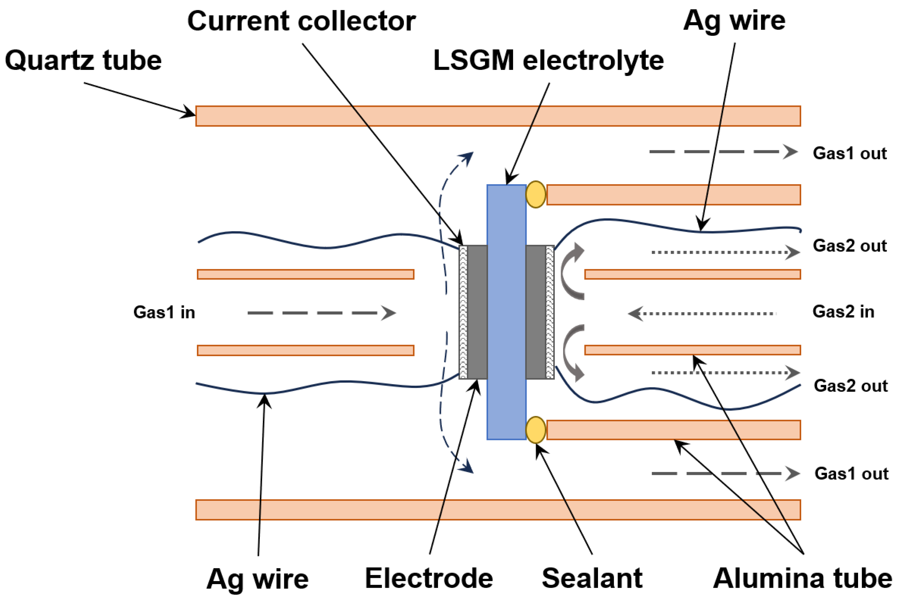
2.2. Cell Fabrication and Test

Electrolyte-supported symmetrical cells were fabricated to test the electrochemical performance of electrodes because of their concise and stable structure [34]. The electrode slurry was prepared by blending catalyst powder with SDC (weight ratio of catalyst:SDC = 6:4), α-terpineol solvent, and ethyl cellulose binder uniformly in an agate mortar for 2 h. The slurry was screen-printed on both sides of the LSGM electrolyte pellets (~200 μm in thickness, 12 mm in diameter) with an active area of ~0.5 cm2. The SOC was fabricated after calcining the above electrode at 1050 °C for 2 h with a ramp rate of 3 °C min−1.
Figure 1 shows a simple schematic diagram of the homemade single-cell test equipment. The test apparatus was designed with adjustable gas flow and composition on both sides of the cell. The SOC was sealed on the top of an alumina tube with ceramic sealant (Aremco, 552-VFG (Valley Cottage, NY, USA)) before being placed in a quartz tube, then heated up to specific temperatures. Ag mesh, painted with Ag paste, was selected as the current collector on the electrode surfaces. The electrochemical property of the cell was measured using a 2-probe method. The current density–cell voltage–power density (i–V–P) curves were produced on a Solartron 1287 electrochemical interface instrument, and the EIS (electrochemical impedance spectra) were measured using a Solartron 1260 frequency response analyzer. Polarization curves were obtained using a linear sweep rate of 0.01 V s−1 from OCV to 0.2 V for SOFC and OCV to 1.6 V for SOEC at the specific gas atmosphere. The EIS data were measured at a stable OCV with a frequency range from 100 kHz to 0.1 Hz and an amplitude of 10 mV at the specific gas environment. For both the SOFC and SOEC modes, the ratio of steam was controlled by setting the water bath temperature according to the saturated steam pressure curve. The total flow rate of the H2O–H2 mixture to the hydrogen electrode was 50 mL min−1. The oxygen electrode was exposed to ambient air.
The exhaust gas of the SOEC, dried by color-changing silica gel (blue glue), flowed through a hydrogen flowmeter to estimate the H2 production.

2.3. Characterization Methods

The phase structures of the samples were carried out on an X-ray diffractometer (XRD, BRUKER D8 ADVANCE, 40 kV, 25 mA). The scan speed and step size for the XRD analysis were 10° min−1 and 0.02°, respectively. Scanning electron microscopy (SEM, JSM-6701 F) and transmission electron microscopy (TEM, JEOL JEM-F200) were employed to investigate the micro-structures of the synthesized catalysts. X-ray photoelectron spectrometry (XPS, Thermo Scientific ESCALAB 250Xi (Waltham, MA, USA)) was performed to identify the chemical valence states of various elements in the as-prepared samples.

2.4. Theoretical Calculations

The spin-polarized first-principle calculation was performed in the framework of density functional theory, as implemented in the VASP program [35]. The generalized Perdew–Burke–Enzerh gradient approximation was employed for the electronic exchange and correlation. The plane-wave pseudopotential with a kinetic cutoff energy of 450 eV within the projector augmented wave (PAW) method was used [36,37]. The self-consistent total energy convergence criteria were less than 10−4 eV, and the geometry optimization was terminated when the forces on all atoms were smaller than 0.02 eV Å−1. For all models, the vacuum space along the z-direction was set to 15 Å, which was enough to avoid interactions between the two neighboring images. The K-point was generated by the Monkhorst–Pack grid method at 2 × 2 × 1 [38] for geometry optimization. The free energy was calculated using Equation (1):
G = Eads + ZPE + TS
where G, Eads, ZPE, and TS are the free energy, total energy from DFT calculations, zero-point energy, and entropic contributions, respectively, at T = 1073 K.

3. Results and Discussions

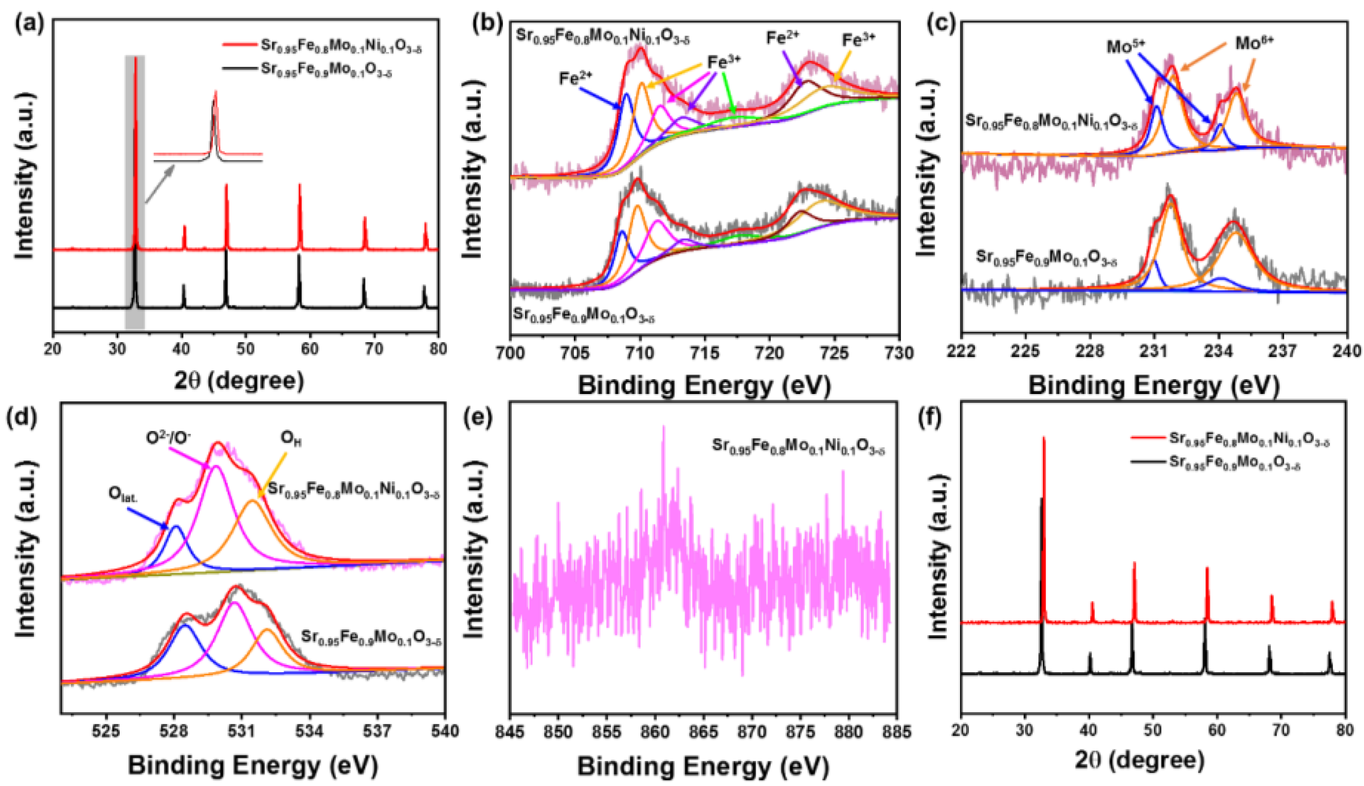
3.1. Structural Characterizations

XRD and XPS structural characterizations for the Sr0.9Fe0.9Mo0.1O3−δ and Sr0.9Fe0.8Mo0.1Ni0.1O3−δ powders were carried out, and the results are shown in Figure 2. The XRD pattern of Sr0.95Fe0.9Mo0.1O3−δ in Figure 2a shows typical diffraction peaks at 32.6, 40.3, 46.8, 58.2, 68.3, and 77.7°, which matched well with the characteristic peaks of SrFeO3−x (JCPDS 34-0638). After Ni doping, all of the diffraction peaks shifted to higher 2θ values, indicating volumetric shrinkage of the crystal lattice of Sr0.95Fe0.8Mo0.1Ni0.1O3−δ because of the smaller ionic radius of Ni than Fe. Conversely, the movement of the diffraction peaks in Sr0.95Fe0.8Mo0.1Ni0.1O3−δ also confirmed that the Ni element was successfully doped into the crystal lattice of Sr0.95Fe0.9Mo0.1O3−δ [9,39,40]. The XRD results verified that Sr0.95Fe0.9Mo0.1O3−δ and Sr0.95Fe0.8Mo0.1Ni0.1O3−δ with pure perovskite structures were fabricated [27,41].
The surface chemistries were surveyed using XPS, and the results are illustrated in Figure 2b–e. For Sr0.95Fe0.9Mo0.1O3−δ, Fe2+ at 708.6/722.1 eV and Fe3+ at 709.8/711.3/713.4/717.7/723.9 eV were observed in Figure 2b [8,28]. The Mo 3d XPS spectra could be de-convoluted into two pairs of peaks (Figure 2c), which could be assigned to Mo5+ (231.8/234.8 eV) and Mo6+ (231.0/234.1 eV) [26,28,42,43]. The O1s XPS spectra displayed three peaks at 528.5, 530.7, and 532.1 eV (Figure 2d), which could be indexed to the lattice oxygen (Olat.), surface adsorbed oxygen (O2−/O), and surface adsorbed molecular water (OH), respectively [25,26,28]. Sr0.95Fe0.8Mo0.1Ni0.1O3−δ exhibited similar Fe 2p, Mo 3d, and O 1s XPS spectra with those of Sr0.95Fe0.9Mo0.1O3−δ, while the Fe 2p XPS spectra moved to higher binding energies and the O 1s XPS spectra moved to the lower binding energies; moreover, the content of lattice oxygen and Mo6+ decreased, and the content of adsorbed oxygen and water increased, indicating the Ni doping fabricated the generation of oxygen vacancies in Sr0.95Fe0.9Mo0.1O3−δ because of the in situ exsolution properties of B-site doping [8,24,25]. The binding energy assigned to Ni2+ can be observed in Figure 2e, indicating the successful doping of Ni into Sr0.95Fe0.9Mo0.1O3−δ [6,22,25,44]. The XPS results confirmed the co-existence of Fe2+/Fe3+, Mo5+/Mo6+, and oxygen vacancies in Sr0.95Fe0.8Mo0.1Ni0.1O3−δ, and Ni doping adjusted the Fe2+/Fe3+ and Mo5+/Mo6+ redox couples and content of oxygen vacancies in Sr0.95Fe0.8Mo0.1Ni0.1O3−δ. The co-existence of Fe2+/Fe3+ and Mo5+/Mo6+ redox couples could provide continuous electron jump paths to promote electron transport [24]. The abundant oxygen vacancies could provide plenty of active sites and fabricate oxygen ion conduction during the surface reaction of the electrodes [26,28].
To evaluate the thermodynamic stability, the diffractograms of Sr0.95Fe0.8Mo0.1Ni0.1O3−δ and Sr0.95Fe0.9Mo0.1O3−δ after reduction were analyzed. After treatment in 5% H2-Ar at 800 °C for 5 h, both Sr0.95Fe0.8Mo0.1Ni0.1O3−δ and Sr0.95Fe0.9Mo0.1O3−δ exhibited pure perovskite structures without any impurities and diffraction peaks movement (Figure 2f), indicating the high thermodynamic stability of Sr0.95Fe0.8Mo0.1Ni0.1O3−δ and Sr0.95Fe0.9Mo0.1O3−δ under reduction conditions, which offers great promise in meeting the requirement of reaction stability in practical SOC applications [22,23,24].

3.2. Morphological Characterization

The as-prepared Sr0.95Fe0.9Mo0.1O3−δ and Sr0.95Fe0.8Mo0.1Ni0.1O3−δ displayed branched rod-like and flake morphologies with connected particles, respectively; the diameters of the particles were 0.5–2 μm (Figure 3a–d). TEM images in Figure 3e,h confirmed the connected particles of Sr0.95Fe0.9Mo0.1O3−δ and Sr0.95Fe0.8Mo0.1Ni0.1O3−δ. In the high-resolution TEM (HRTEM) images in Figure 3f, lattice spacings of 0.224 and 0.158 nm, corresponding to the (111) and (211) planes of perovskite, were observed in Sr0.95Fe0.9Mo0.1O3−δ, while lattice spacings of 0.214 and 0.270 nm, indexed to the (111) and (110) planes of perovskite, could be detected in Sr0.95Fe0.8Mo0.1Ni0.1O3−δ (Figure 3i). The reduced (111) lattice distance in Sr0.95Fe0.8Mo0.1Ni0.1O3−δ verified the successful doping of Ni into Sr0.95Fe0.9Mo0.1O3−δ, which is consistent with the XRD results. The homogeneous distributions of Sr, Fe, Mo, and O in Figure 3g and Sr, Fe, Mo, Ni, and O in Figure 3j further affirmed the formation of Sr0.95Fe0.9Mo0.1O3−δ and Sr0.95Fe0.8Mo0.1Ni0.1O3−δ.

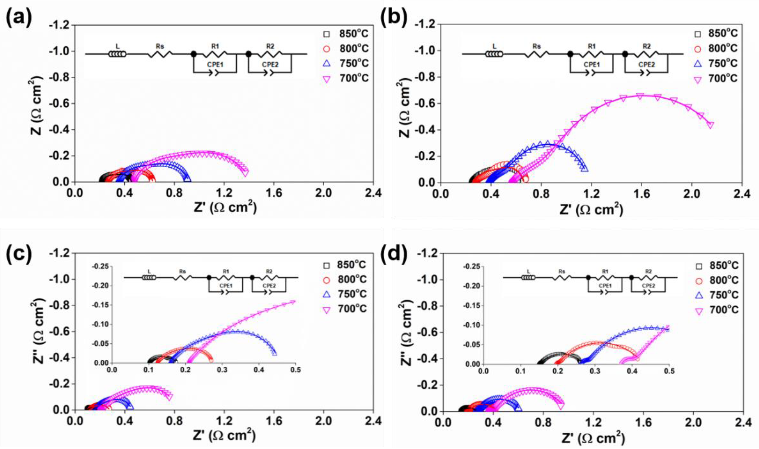
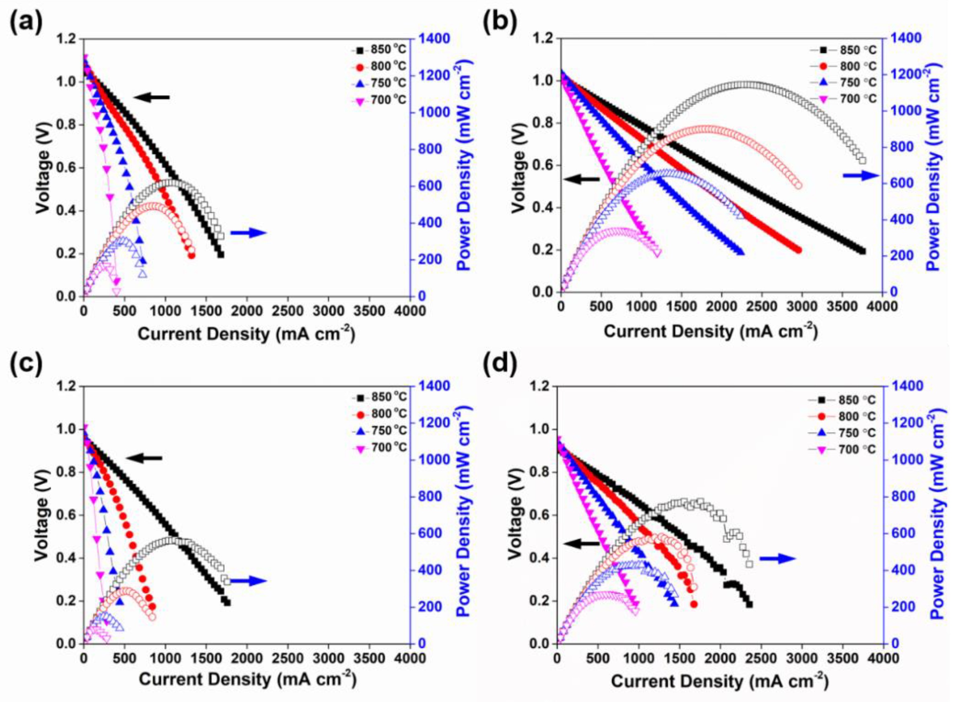
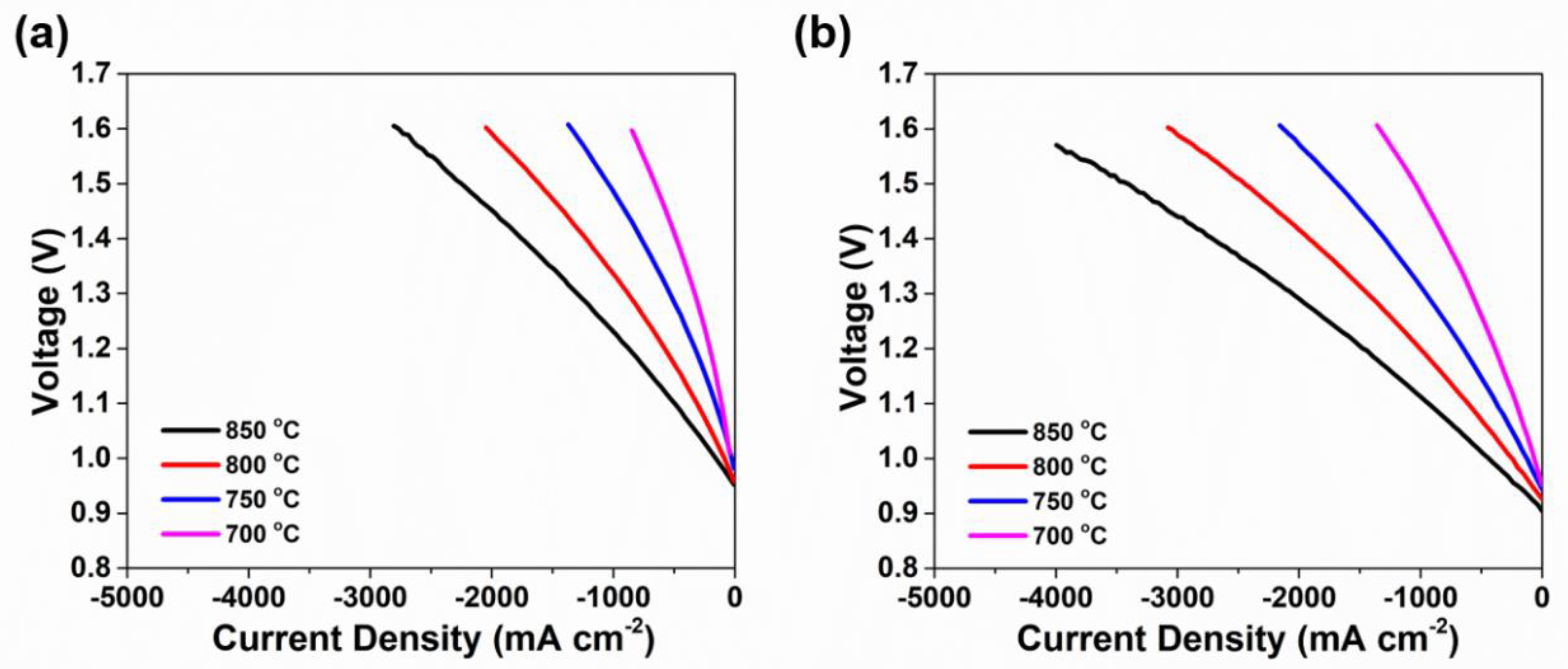
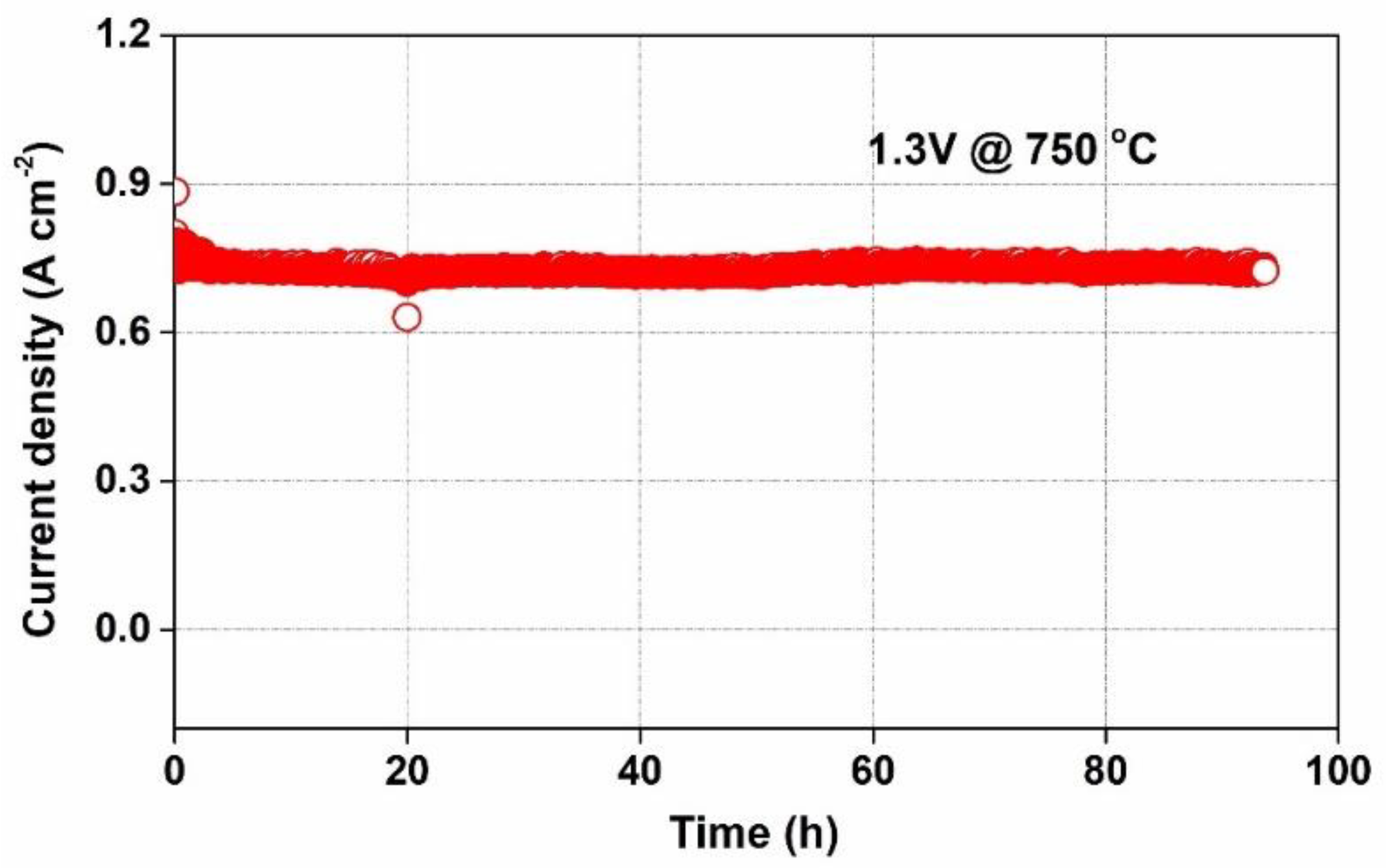
3.3. Electrochemical Performance

Figure 4 shows the Nyquist plots with the equivalent circuit insert of the SFM-SDC/LSGM/SFM-SDC and SFMN-SDC/LSGM/SFMN-SDC symmetrical cells. The interfacial polarization resistances (Rp) of SFM-SDC/LSGM/SFM-SDC at 700, 750, 800, and 850 °C were 0.92, 0.55, 0.35, and 0.23 Ω cm2 in air, respectively, and 1.82, 0.80, 0.43, and 0.41 Ω cm2 in wet H2 (Figure 4a,b), respectively. Noticeably, the SFMN-SDC/LSGM/SFMN-SDC symmetrical cells exhibited lower Rp values of 0.55, 0.28, 0.15, and 0.07 Ω cm2 in air, respectively, and 0.58, 0.35, 0.22, and 0.11 Ω cm2 in wet H2 at the above-mentioned temperatures (Figure 4c,d), respectively, suggesting the great promise of Sr0.95Fe0.8Mo0.1Ni0.1O3−δ as an electro-catalyst for SOC applications [2,10,44,45].
According to the i–V–P curves in the SOFC mode, when feeding 3% H2O-humidified H2 to the anode and static ambient air to the cathode, both SFM-SDC/LSGM/SFM-SDC and SFMN-SDC/LSGM/SFMN-SDC single cells presented open-circuit voltage (OCV) values above 1.0 V at 700–850 °C (Figure 5a,b). The OCV values were close to the theoretical Nernst potential at the corresponding temperature, portending that the tested cells were well sealed without gas leakage [8,28]. The peak power densities of SFM-SDC/LSGM/SFM-SDC at 700, 750, 800, and 850 °C were 167.0, 301.6, 492.1, and 619.0 mW cm−2, respectively, which remarkably increased to 341.0, 653.8, 900.1, and 1145.0 mW cm−2, respectively, for the SFMN-SDC/LSGM/SFMN-SDC single cells. When feeding 50% H2O-humidified H2 to the anode, the peak power densities of SFM-SDC/LSGM/SFM-SDC at 700, 750, 800, and 850 °C, respectively, decreased to 272.0, 429.1, 581.9, and 774.4 mW cm−2 immediately, while SFMN-SDC/LSGM/SFMN-SDC maintained high values of 272.0, 429.1, 578.1, and 773.8 mW cm−2 (Figure 5c,d), respectively. These results elaborated on the superior electrochemical performance of the Sr0.95Fe0.8Mo0.1Ni0.1O3−δ electrode.
The i–V curves of the SOEC electrolysis for SFM-SDC/LSGM/SFM-SDC and SFMN-SDC/LSGM/SFMN-SDC single cells are shown in Figure 6. When exposed to a gas mixture of H2O/H2 (50:50), the electrolysis current densities at 700, 750, 800, and 850 °C at 1.3 V were 328.2, 528.8, 886.9, and 1288.1 mA cm−2 for SFM-SDC/LSGM/SFM-SDC (Figure 6a), respectively. As expected, higher values of 560.0, 959.5, 1438.8, and 2078.4 mA cm−2 were obtained for SFMN-SDC/LSGM/SFMN-SDC (Figure 6b), respectively. The results indicated that the partial substitution of Fe with Ni improved the steam-splitting performance of Sr0.95Fe0.9Mo0.1O3−δ. The H2 production was measured to be approximately 5.5 and 9.8 mL min−1×cm−2, respectively, with Faradaic efficiencies of 89.01% and 97.77%, respectively.
Figure 7 shows the electrochemical impedance spectra with the equivalent circuit insert of the LSGM-supported symmetrical cells with 3% H2O-humidified H2 fed to the anode. The impedance spectrum exhibited similar shapes at different temperatures, suggesting that the reaction mechanism generally did not change with temperature. Table 1 summarizes the resistance parameters; it can be clearly observed that both ohmic resistances (Rs) and polarization resistances (Rp) of the electrolytic cells decreased as the temperature increased, which consequently resulted in remarkable improvements in cell performance. The ohmic resistance can be attributed to the electrolyte thickness, the contact resistance at the interfaces, and the resistance contribution of the current collectors and contacts [46]. The Rp values decreased with increasing temperature; at lower temperatures, the charge transfer turned out to be the dominant resistance contributor, whereas, at higher temperatures, ionic transport between the electrolyte and electrode was the rate-limiting step for the electrode reaction. At evaluated temperatures of 850, 800, 750, and 700 °C, the Rp values of the SFM were 0.20, 0.46, 0.80, and 1.54 Ω cm2, respectively. The SFMN exhibited significantly reduced Rp values of 0.13, 0.17, 0.24, and 0.48 Ω cm2, respectively. The decreased polarization resistances of Sr0.95Fe0.8Mo0.1Ni0.1O3−δ indicated the higher electrochemical activity and higher ion diffusion of the Sr0.95Fe0.8Mo0.1Ni0.1O3–δ electrode because of Ni doping, which induced more oxygen vacancies and balanced the Fe2+/Fe3+ and Mo5+/Mo6+ redox couples, resulting in excellent electrochemical performance for SOEC and SOFC applications [27,28].
To evaluate the stability of the SOEC with an SFMN electrode, a potentiostatic test was conducted under a constant applied potential load of 1.3 V at 750 °C, and the corresponding curve is presented in Figure 8. With a gas mixture of H2O/H2 (50:50) fed to the cathode, the cell achieved a stable current density of ~0.73 A cm−2 with a faint increase for about 94 h, indicating the SFMN electrode had good stability under the applied conditions.
Figure 9 presents the cell microstructural characteristics after the test for the SFMN-SDC/LSGM/SFMN-SDC single cell. A cross-section of the cell after the 94 h test is shown in Figure 9a. The thicknesses of the electrodes and the LSGM electrolyte layer for the symmetrical cell were approximately 20 μm and 200 μm, respectively. For the anode, the loose and porous structure could facilitate the transmission and diffusion of the reaction gas (Figure 9b). Some metal particle growth was observed on the cathode surface (Figure 9c,d); this could be attributed to the in situ exsolved nanoparticle catalysts on the perovskite backbone surface [28]. It also can be seen that both electrodes remained in a porous state and exhibited nice contact with the electrolyte without electrode peeling, suggesting good thermal compatibility between the electrodes and electrolyte.

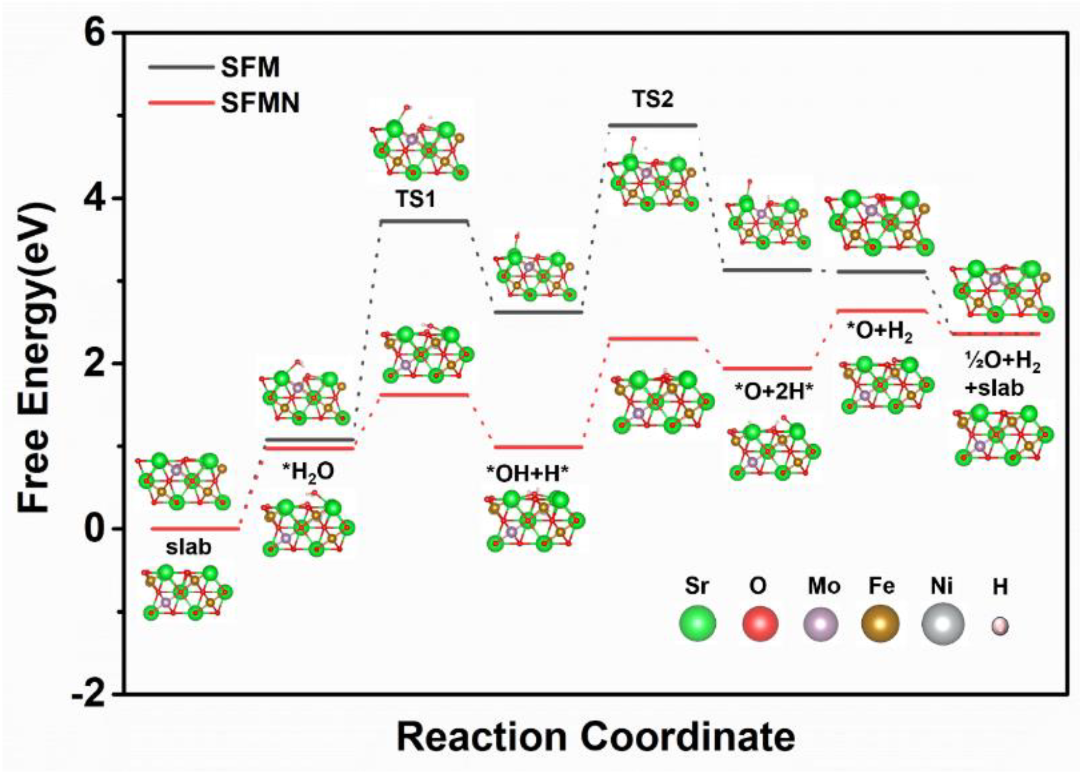
3.4. H2O Reduction Pathway on the SFM/SFMN (111) Surface

SrFeO3 with a cubic structure (space group Pm-3m) was adopted in the calculations; the cubic unit cell structure of SrFeO3 and possible Mo–Ni atom arrangements of Sr0.95Fe0.8Mo0.1Ni0.1O3−δ in a 3 × 3 × 3 supercell are displayed in Figure 10. The lattice parameters a, b, and c changed from 3.91 Å, 3.94 Å, and 3.91 Å for SFM to 3.83 Å, 3.88 Å, and 3.92 Å for SFMN, owing to the doping of Ni to Fe sites, which resulted in a smaller cell volume and slight lattice distortion, consistent with the XRD and TEM results.
The Gibbs free energy diagrams for thermochemical water splitting at 1073 K, standard pressure, and ΔV = 1.29 V are shown in Figure 11. Since the water electrolysis mechanism is still under investigation and discussion, one possible pathway of water splitting was proposed to examine the water reduction mechanism on the (111) surface of SFM and SFMN. In the initial step, a H2O molecule is chemically adsorbed on the (111) surface of SFM and SFMN, with adsorption energies of 1.08 eV and 0.97 eV, respectively. Then, the H2O is transformed into OH* and H* by overcoming an energy barrier of 0.65 eV on the SFMN surface (Equation (2)), which is 1.99 eV less than the corresponding energy barrier on SFM, suggesting the higher surface catalysis activity with Ni doping. The transition state of the *H2O → *OH + H* step is labeled as TS1. The adsorption of OH* + H* was 0.99 eV for SFMN and 1.62 eV for SFM. Reaction energy gaps of 1.31 eV and 2.26 eV for SFM and SFMN, respectively, suggest significant enhancement of the OH* transformation (labeled as TS2, Equation (3)), which was also considered the RDS for the whole process (Equation (4)). It is noteworthy that in the following step, the H2 was released to the gas phase with an energy difference of −0.02 eV for SFM and 0.70 eV for SFMN (Equation (5)).
H2O + 2* → OH* + H*
OH* + * → O* + H*
O* + 2e → O2− + *
2H* → H2 + 2*

4. Conclusions

In summary, Sr0.9Fe0.9Mo0.1O3−δ and Sr0.9Fe0.8Mo0.1Ni0.1O3−δ perovskite ceramic electrodes were synthesized using a glycine combustion method and evaluated as electrodes on both the hydrogen and oxygen sides of RS-SOCs. In the SOFC mode, a high power density of 1.145 W cm−2 at 850 °C on a symmetrical cell could be achieved, and a current density of 3.995 A cm−2 was obtained at 850 °C and 1.6 V in the SOEC mode. Furthermore, no degradation was observed during the stability test, suggesting that SFMN may be a potential catalyst for water splitting at high temperatures. Characterization results and theoretical calculations verified that Ni doping adjusted the Fe2+/Fe3+ and Mo5+/Mo6+ redox couples and induced more oxygen vacancies in Sr0.95Fe0.8Mo0.1Ni0.1O3−δ, which promoted electron transport and provided plenty of active sites for electrode reactions. The Gibbs free energy of water electrolysis reactions on the (111) surface exhibited a significant decrease with Ni-doped SFM on the B-site, as proved with DFT calculations. This research provides new guidance for the rational design of high-performance electrode materials for SOFCs and SOECs.

Author Contributions

Conceptualization, Y.G. and L.B.; methodology, Y.G. and L.B.; software, W.G.; validation, Y.G. and L.B.; formal analysis, Y.G.; investigation, F.W.; resources, Z.W. and F.W.; data curation, Y.G.; writing—original draft preparation, Y.G.; writing—review and editing, Y.G. and Y.W.; visualization, W.G. and Z.W.; supervision, J.W.; project administration, J.W.; funding acquisition, Y.G. All authors have read and agreed to the published version of the manuscript.

Funding

This work was financially supported by the Huaneng Clean Energy Research Institute (Grant No. CERI/TL-22-CERI02).

Data Availability Statement

If raw data is required, please contact the corresponding author.

Conflicts of Interest

The authors declare no conflict of interest.

References

  1. Zhang:, L.; Xu, C.; Sun, W.; Ren, R.; Yang, X.; Luo, Y.; Qiao, J.; Wang, Z.; Zhen, S.; Sun, K. Constructing perovskite/alkaline-earth metal composite heterostructure by infiltration to revitalize CO2 electrolysis. Sep. Purif. Technol. 2022, 298, 121475. [Google Scholar] [CrossRef]
  2. Xi, X.; Fan, Y.; Zhang, J.; Luo, J.-L.; Fu, X.-Z. In situ construction of hetero-structured perovskite composites with exsolved Fe and Cu metallic nanoparticles as efficient CO2 reduction electrocatalysts for high performance solid oxide electrolysis cells. J. Mater. Chem. A 2022, 10, 2509–2518. [Google Scholar] [CrossRef]
  3. Sun, C.; Bian, L.; Qi, J.; Yu, W.; Li, S.; Hou, Y.; Wang, L.; Peng, J.; An, S. Boosting CO2 directly electrolysis by electron doping in Sr2Fe1.5Mo0.5O6-δ double perovskite cathode. J. Power Sources 2022, 521, 230984. [Google Scholar] [CrossRef]
  4. Li, J.; Zhang, J.; Shen, J.K.; Wu, H.H.; Chen, H.P.; Yuan, C.Z.; Wu, N.T.; Liu, G.L.; Guo, D.L.; Liu, X.M. Self-supported electrocatalysts for the hydrogen evolution reaction. Mater. Chem. Front. 2023, 7, 567–606. [Google Scholar] [CrossRef]
  5. Wu, H.H.; Zhuo, F.; Qiao, H.; Venkataraman, L.K.; Zheng, M.; Wang, S.; Huang, H.; Li, B.; Mao, X.; Zhang, Q. Polymer-/Ceramic-based Dielectric Composites for Energy Storage and Conversion. Energy Environ. Mater. 2022, 5, 486–514. [Google Scholar] [CrossRef]
  6. Li, J.; Zhang, Q.M.; Zhang, J.; Wu, N.T.; Liu, G.L.; Chen, H.P.; Yuan, C.Z.; Liu, X.M. Optimizing electronic structure of porous Ni/MoO2 heterostructure to boost alkaline hydrogen evolution reaction. J. Colloid Interface Sci. 2022, 627, 862–871. [Google Scholar] [CrossRef]
  7. Shimada, H.; Yamaguchi, T.; Kishimoto, H.; Sumi, H.; Yamaguchi, Y.; Nomura, K.; Fujishiro, Y. Nanocomposite electrodes for high current density over 3 A cm(-2) in solid oxide electrolysis cells. Nat. Commun. 2019, 10, 5432. [Google Scholar] [CrossRef] [Green Version]
  8. Zhang, X.; Tong, Y.; Liu, T.; Zhang, D.; Yu, N.; Zhou, J.; Li, Y.; Gu, X.K.; Wang, Y. Robust Ruddlesden-Popper phase Sr3Fe1.3Mo0.5Ni0.2O7-δ decorated with in-situ exsolved Ni nanoparticles as an efficient anode for hydrocarbon fueled solid oxide fuel cells. SusMat 2022, 2, 487–501. [Google Scholar] [CrossRef]
  9. Sun, Z.; Liu, Z.; Cai, C.; Deng, H.; Yang, F.; Lu, Y.; Song, X.; An, S.; Zhao, H. High performance oxygen permeation membrane: Sr and Ti co-doped BaFeO3-δ ceramics. Sep. Purif. Technol. 2022, 289, 120742. [Google Scholar] [CrossRef]
  10. Peng, L.; Li, Q.; Sun, L.; Zhao, H. An Effective Strategy to Enhance the Electrocatalytic Activity of Ruddlesden−Popper Oxides Sr3Fe2O7−δ Electrodes for Solid Oxide Fuel Cells. Catalysts 2021, 11, 1400. [Google Scholar] [CrossRef]
  11. Li, Y.; Tian, Y.; Li, J.; Pu, J.; Chi, B. Sr-free orthorhombic perovskite Pr0.8Ca0.2Fe0.8Co0.2O3-δ as a high-performance air electrode for reversible solid oxide cell. J. Power Sources 2022, 528, 231202. [Google Scholar] [CrossRef]
  12. Krammer, M.; Schmid, A.; Siebenhofer, M.; Bumberger, A.E.; Herzig, C.; Limbeck, A.; Kubicek, M.; Fleig, J. Formation and Detection of High-Pressure Oxygen in Closed Pores of La(0.6)Sr(0.4)CoO(3-delta) Solid Oxide Electrolysis Anodes. ACS Appl. Energy Mater. 2022, 5, 8324–8335. [Google Scholar] [CrossRef] [PubMed]
  13. Jing, J.; Pang, J.; Chen, L.; Zhang, H.; Lei, Z.; Yang, Z. Structure, synthesis, properties and solid oxide electrolysis cells application of Ba(Ce, Zr)O3 based proton conducting materials. Chem. Eng. J. 2022, 429, 132314. [Google Scholar] [CrossRef]
  14. Ling, Y.; Wu, Y.; Tian, Y.; Wang, X.; Shen, S.; Ou, X.; Wang, S. Stable solid oxide electrolysis cells with SSF-based symmetrical electrode for direct high-temperature steam electrolysis. Ceram. Int. 2022, 48, 981–991. [Google Scholar] [CrossRef]
  15. Bernadet, L.; Moncasi, C.; Torrell, M.; Tarancón, A. High-performing electrolyte-supported symmetrical solid oxide electrolysis cells operating under steam electrolysis and co-electrolysis modes. Int. J. Hydrogen Energy 2020, 45, 14208–14217. [Google Scholar] [CrossRef]
  16. Zhou, J.; Shin, T.-H.; Ni, C.; Chen, G.; Wu, K.; Cheng, Y.; Irvine, J.T.S. In Situ Growth of Nanoparticles in Layered Perovskite La0.8Sr1.2Fe0.9Co0.1O4−δ as an Active and Stable Electrode for Symmetrical Solid Oxide Fuel Cells. Chem. Mater. 2016, 28, 2981–2993. [Google Scholar] [CrossRef]
  17. Tian, Y.; Wang, W.; Liu, Y.; Naden, A.; Xu, M.; Wu, S.; Chi, B.; Pu, J.; Irvine, J.T.S. Achieving Strong Coherency for a Composite Electrode via One-Pot Method with Enhanced Electrochemical Performance in Reversible Solid Oxide Cells. ACS Catal. 2021, 11, 3704–3714. [Google Scholar] [CrossRef]
  18. Li, Q.; Kuang, K.; Sun, Y.; Zheng, Y.; Liu, Q.; Chan, S.H.; Zhang, H.; Wang, W.; Li, T.; Wang, J. Deficiency of hydrogen production in commercialized planar Ni-YSZ/YSZ/LSM-YSZ steam electrolysis cells. Int. J. Hydrogen Energy 2022, 47, 23514–23519. [Google Scholar] [CrossRef]
  19. Heng, Z.; Wan, Y.; Xia, C. Calcium stabilized La0.6Sr0.4Fe0.8Mn0.2O3-δ perovskite as ceramic fuel electrode for solid oxide cell. J. Power Sources 2022, 537, 231535. [Google Scholar] [CrossRef]
  20. Wang, W.; Tian, Y.; Liu, Y.; Abhishek, N.; Li, Y.; Chi, B.; Pu, J. Tailored Sr-Co-free perovskite oxide as an air electrode for high-performance reversible solid oxide cells. Sci. China Mater. 2021, 64, 1621–1631. [Google Scholar] [CrossRef]
  21. Duan, N.; Yang, J.; Gao, M.; Zhang, B.; Luo, J.-L.; Du, Y.; Xu, M.; Jia, L.; Chi, B.; Li, J. Multi-functionalities enabled fivefold applications of LaCo0.6Ni0.4O3−δ in intermediate temperature symmetrical solid oxide fuel/electrolysis cells. Nano Energy 2020, 77, 105207. [Google Scholar] [CrossRef]
  22. Liu, T.; Zhao, Y.; Zhang, X.; Zhang, H.; Jiang, G.; Zhao, W.; Guo, J.; Chen, F.; Yan, M.; Zhang, Y.; et al. Robust redox-reversible perovskite type steam electrolyser electrode decorated with in situ exsolved metallic nanoparticles. J. Mater. Chem. A 2020, 8, 582–591. [Google Scholar] [CrossRef]
  23. Li, M.; Dong, J.; Chen, Z.; Huang, K.; Xiong, K.; Li, R.; Rao, M.; Chen, C.; Ling, Y.; Lin, B. Excessive Na-Doped La0.75Sr0.25Cr0.5Fe0.4Cu0.1O3-δ Perovskite as an Additional Internal Reforming Catalyst for Direct Carbon Dioxide-Ethanol Solid Oxide Fuel Cells. Catalysts 2022, 12, 1600. [Google Scholar]
  24. Wang, S.; Jiang, H.; Gu, Y.; Yin, B.; Chen, S.; Shen, M.; Zheng, Y.; Ge, L.; Chen, H.; Guo, L. Mo-doped La0.6Sr0.4FeO3-δ as an efficient fuel electrode for direct electrolysis of CO2 in solid oxide electrolysis cells. Electrochim. Acta 2020, 337, 135794. [Google Scholar] [CrossRef]
  25. Lv, H.; Lin, L.; Zhang, X.; Gao, D.; Song, Y.; Zhou, Y.; Liu, Q.; Wang, G.; Bao, X. In situ exsolved FeNi3 nanoparticles on nickel doped Sr2Fe1.5Mo0.5O6−δ perovskite for efficient electrochemical CO2 reduction reaction. J. Mater. Chem. A 2019, 7, 11967–11975. [Google Scholar] [CrossRef]
  26. Hou, Y.; Wang, Y.; Wang, L.; Zhang, Q.; Chou, K.-C. Electrochemical properties of La0.5Sr0.5Fe0.95Mo0.05O3−δ as cathode materials for IT-SOEC. RSC Adv. 2021, 11, 32077–32084. [Google Scholar] [CrossRef]
  27. Xu, C.; Zhen, S.; Ren, R.; Chen, H.; Song, W.; Wang, Z.; Sun, W.; Sun, K. Cu-Doped Sr2Fe1.5Mo0.5O6-δ as a highly active cathode for solid oxide electrolytic cells. Chem. Commun. 2019, 55, 8009–8012. [Google Scholar] [CrossRef]
  28. Du, Z.; Zhao, H.; Yi, S.; Xia, Q.; Gong, Y.; Zhang, Y.; Cheng, X.; Li, Y.; Gu, L.; Swierczek, K. High-Performance Anode Material Sr2FeMo0.65Ni0.35O6-delta with In Situ Exsolved Nanoparticle Catalyst. ACS Nano 2016, 10, 8660–8669. [Google Scholar] [CrossRef]
  29. Zheng, K.; Świerczek, K.; Polfus, J.M.; Sunding, M.F.; Pishahang, M.; Norby, T. Carbon Deposition and Sulfur Poisoning in SrFe0.75Mo0.25O3-δ and SrFe0.5Mn0.25Mo0.25O3-δ Electrode Materials for Symmetrical SOFCs. J. Electrochem. Soc. 2015, 162, F1078. [Google Scholar] [CrossRef]
  30. Tian, Y.; Zheng, H.; Zhang, L.; Chi, B.; Pu, J.; Li, J. Direct Electrolysis of CO2 in Symmetrical Solid Oxide Electrolysis Cell Based on La0.6Sr0.4Fe0.8Ni0.2O3-δ Electrode. J. Electrochem. Soc. 2018, 165, F17. [Google Scholar] [CrossRef]
  31. Irshad, M.; Ain, Q.u.; Siraj, K.; Raza, R.; Tabish, A.N.; Rafique, M.; Idrees, R.; Khan, F.; Majeed, S.; Ahsan, M. Evaluation of BaZr0.8X0.2 (X = Y, Gd, Sm) proton conducting electrolytes sintered at low temperature for IT-SOFC synthesized by cost effective combustion method. J. Alloys Compd. 2020, 815, 152389. [Google Scholar] [CrossRef]
  32. Irshad, M.; Khalid, M.; Rafique, M.; Tabish, A.N.; Shakeel, A.; Siraj, K.; Ghaffar, A.; Raza, R.; Ahsan, M.; Ain, Q.T.; et al. Electrochemical Investigations of BaCe0.7-xSmxZr0.2Y0.1O3-δ Sintered at a Low Sintering Temperature as a Perovskite Electrolyte for IT-SOFCs. Sustainability 2021, 13, 12595. [Google Scholar] [CrossRef]
  33. Irshad, M.; Rafique, M.; Tabish, A.N.; Ghaffar, A.; Shakeel, A.; Siraj, K.; Ain, Q.U.; Raza, R.; Assiri, M.A.; Imran, M. Influence of Sintering Temperature on the Structural, Morphological, and Electrochemical Properties of NiO-YSZ Anode Synthesized by the Autocombustion Route. Metals 2022, 12, 219. [Google Scholar] [CrossRef]
  34. Peng, X.; Tian, Y.; Liu, Y.; Wang, W.; Jia, L.; Pu, J.; Chi, B.; Li, J. An efficient symmetrical solid oxide electrolysis cell with LSFM-based electrodes for direct electrolysis of pure CO2. J. CO2 Util. 2020, 36, 18–24. [Google Scholar] [CrossRef]
  35. Kresse, G.; Furthmüller, J. Efficiency of ab-initio total energy calculations for metals and semiconductors using a plane-wave basis set. Comput. Mater. Sci. 1996, 6, 15–50. [Google Scholar] [CrossRef]
  36. Perdew, J.P.; Burke, K.; Ernzerhof, M. Generalized Gradient Approximation Made Simple. Phys. Rev. Lett. 1996, 77, 3865–3868. [Google Scholar] [CrossRef] [Green Version]
  37. Kresse, G.; Furthmüller, J. Efficient iterative schemes for ab initio total-energy calculations using a plane-wave basis set. Phys. Rev. B 1996, 54, 11169–11186. [Google Scholar] [CrossRef]
  38. Monkhorst, H.J.; Pack, J.D. Special points for Brillouin-zone integrations. Phys. Rev. B 1976, 13, 5188–5192. [Google Scholar] [CrossRef]
  39. Guo, S.; Liu, G.; Han, T.; Zhang, Z.; Liu, Y. K-Modulated Co Nanoparticles Trapped in La-Ga-O as Superior Catalysts for Higher Alcohols Synthesis from Syngas. Catalysts 2019, 9, 218. [Google Scholar] [CrossRef] [Green Version]
  40. Xu, J.; Wan, S.; Wang, Y.; Huang, S.; Yuan, Z.; Chen, F.; Zhang, Y.; Liu, T. Enhancing performance of molybdenum doped strontium ferrite electrode by surface modification through Ni infiltration. Int. J. Hydrogen Energy 2021, 46, 10876–10891. [Google Scholar] [CrossRef]
  41. Yang, L.; Li, Y.; Hou, Z.; Shi, C.; Zhang, G.; Zeng, F.; Zhou, J.; Wang, S. La1-xCaxFeO3-δ air electrode fabricated by glycine-nitrate combustion method for solid oxide electrolysis cell. Ceram. Int. 2021, 47, 32318–32323. [Google Scholar] [CrossRef]
  42. Liu, G.; Zhang, T.; Li, X.; Li, J.; Wu, N.; Cao, A.; Yuan, W.; Pan, K.M.; Guo, D.; Liu, X. MoS2@C with S vacancies vertically anchored on V2C-MXene for efficient lithium and sodium storage. Inorg. Chem. Front. 2023, 10, 1587–1602. [Google Scholar] [CrossRef]
  43. Liu, G.; Xiao, F.; Zhang, T.; Gu, Y.; Li, J.; Guo, D.; Xu, M.; Wu, N.; Cao, A.; Liu, X. In-situ growth of MoO2@N doped carbon on Mo2C-MXene for superior lithium storage. Appl. Surf. Sci. 2022, 597, 153688. [Google Scholar] [CrossRef]
  44. Tian, Y.; Liu, Y.; Jia, L.; Naden, A.; Chen, J.; Chi, B.; Pu, J.; Irvine, J.T.S.; Li, J. A novel electrode with multifunction and regeneration for highly efficient and stable symmetrical solid oxide cell. J. Power Sources 2020, 475, 228620. [Google Scholar] [CrossRef]
  45. Sun, X.; Ye, Y.; Zhou, M.; Chen, H.; Li, Y.; Chen, P.; Dong, D.; Ling, Y.; Khan, M.; Chen, Y. Layered-perovskite oxides with in situ exsolved Co–Fe alloy nanoparticles as highly efficient electrodes for high-temperature carbon dioxide electrolysis. J. Mater. Chem. A 2022, 10, 2327–2335. [Google Scholar] [CrossRef]
  46. Hernández, E.; Baiutti, F.; Morata, A.; Torrell, M.; Tarancón, A. Infiltrated mesoporous oxygen electrodes for high temperature co-electrolysis of H2O and CO2 in solid oxide electrolysis cells. J. Mater. Chem. A 2018, 6, 9699–9707. [Google Scholar] [CrossRef] [Green Version]
Figure 1. Schematic diagram of single-cell test equipment.
Catalysts 13 01043 g001
Figure 2. (a) XRD patterns, (b) Fe 2p, (c) Mo 3d, (d) O 1s XPS spectra of Sr0.9Fe0.9Mo0.1O3−δ and Sr0.9Fe0.8Mo0.1Ni0.1O3−δ powders, (e) Ni 2p XPS spectra of Sr0.9Fe0.8Mo0.1Ni0.1O3−δ powder, and (f) XRD patterns of Sr0.9Fe0.9Mo0.1O3−δ and Sr0.9Fe0.8Mo0.1Ni0.1O3−δ powders after treated in 5% H2–Ar at 800 °C for 5 h.
Catalysts 13 01043 g002
Figure 3. SEM images of (a,b) Sr0.95Fe0.9Mo0.1O3−δ and (c,d) Sr0.95Fe0.8Mo0.1Ni0.1O3−δ; TEM, HRTEM, and element mappings of (eg) Sr0.95Fe0.9Mo0.1O3−δ and (hj) Sr0.95Fe0.8Mo0.1Ni0.1O3−δ.
Catalysts 13 01043 g003
Figure 4. Electrochemical impedance spectra of SFM-SDC/LSGM/SFM-SDC feeding (a) air and (b) wet H2 to anode and cathode; electrochemical impedance spectra of SFMN-SDC/LSGM/SFMN-SDC feeding (c) air and (d) wet H2 to anode and cathode.
Catalysts 13 01043 g004
Figure 5. Electrochemical performance in SOFC mode: i–V–P curves for (a) SFM-SDC/LSGM/SFM-SDC and (b) SFMN-SDC/LSGM/SFMN-SDC feeding 3% H2O-humidified H2 to anode and static ambient air to cathode; i–V–P curves for (c) SFM-SDC/LSGM/SFM-SDC and (d) SFMN-SDC/LSGM/SFMN-SDC exposing 50% H2O-humidified H2 to anode and static ambient air to cathode.
Catalysts 13 01043 g005
Figure 6. Electrochemical performance in SOEC mode: i–V curves for (a) SFM-SDC/LSGM/SFM-SDC and (b) SFMN-SDC/LSGM/SFMN-SDC flowing 50% H2O-humidified H2 to cathode and static ambient air to anode.
Catalysts 13 01043 g006
Figure 7. Electrochemical impedance spectra of (a) SFM-SDC/LSGM/SFM-SDC and (b) SFMN-SDC/LSGM/SFMN-SDC with feeding 3% H2O-humidified H2 to anode and static ambient air to cathode.
Catalysts 13 01043 g007
Figure 8. Electrolysis stability test with SFMN electrode at a constant applied voltage of 1.3 V at 750 °C.
Catalysts 13 01043 g008
Figure 9. (a) Cross-sectional SEM images for SFMN-SDC/LSGM/SFMN-SDC cells after stability tests, (b) the anode side, (c) the cathode, and (d) the magnified image.
Catalysts 13 01043 g009
Figure 10. Pseudo-cubic unit cell structure of (a) SFM and (b) SFMN in a 3 × 3 × 3 supercell.
Catalysts 13 01043 g010
Figure 11. Gibbs free energy diagram and H2 reduction intermediates for water electrolysis on (111) surface of SFM (black line) and SFMN (red line) at 1073 K, standard pressure, and applied potential of 1.29 V.
Catalysts 13 01043 g011
Table 1. Values of the resistance parameters of SFM-SDC/LSGM/SFM-SDC and SFMN-SDC/LSGM/SFMN-SDC with feeding 3% H2O-humidified H2 to anode and static ambient air to cathode at specific temperatures.
TemperaturesSFM-SDC/LSGM/SFM-SDCSFMN-SDC/LSGM/SFMN-SDC
RsRpRsRp
700 °C0.4041.5410.2800.479
750 °C0.2840.7960.1960.243
800 °C0.2130.4640.1470.175
850 °C0.1580.2000.1150.131
Disclaimer/Publisher’s Note: The statements, opinions and data contained in all publications are solely those of the individual author(s) and contributor(s) and not of MDPI and/or the editor(s). MDPI and/or the editor(s) disclaim responsibility for any injury to people or property resulting from any ideas, methods, instructions or products referred to in the content.

