Article

Catalytic Steam-Reforming of Glycerol over LDHs-Derived Ni–Al Nanosheet Array Catalysts for Stable Hydrogen Production

1
Shandong Provincial Key Laboratory of Biomass Gasification Technology, Energy Research Institute, Qilu University of Technology (Shandong Academy of Sciences), Jinan 250014, China
2
College of Chemistry and Chemical Engineering, Chongqing University of Technology, Chongqing 400054, China
*
Author to whom correspondence should be addressed.
Catalysts 2023, 13(7), 1047; https://doi.org/10.3390/catal13071047
Submission received: 28 April 2023 / Revised: 31 May 2023 / Accepted: 1 June 2023 / Published: 28 June 2023

Abstract

:
In the present work, LDHs-derived Ni–Al nanosheet arrays (NiAl/NA) were successfully synthesized via a one-step hydrothermal method, and applied in the steam-reforming of glycerol reaction for enhanced and stable hydrogen production. The physicochemical properties of catalysts were characterized using various techniques, including XRD, SEM–EDS, XPS, N2-physisorption, Raman, and TG–DTG. The results indicate that smooth and cross-linked Ni–Al mixed metal oxide nanosheets were orderly and perpendicularly grown on the Ni foam substrate. The SEM line scan characterization reveals the metal concentration gradient from the bottom to the top of nanosheet, which leads to distinctly optimized Ni valence states and an optimized binding strength to oxygen species. Owing to the improved reducibility and more exposed active sites afforded by its array structures, the NiAl/NA catalyst shows enhanced glycerol conversion (83.1%) and a higher H2 yield (85.4%), as well as longer stability (1000 min), compared to the traditional Ni–Al nanosheet powder. According to the characterization results of spent catalysts and to density functional theory (DFT) calculations, coke deposition is effectively suppressed via array construction, with only 1.25 wt.% of amorphous carbons formed on NiAl/NA catalyst via CO disproportionation.

1. Introduction

The severe energy crisis and environmental pollution resulting from excessive dependence on fossil fuels have prompted governments and researchers around the world to place great emphasis on the development and use of clean and renewable energy sources. Hydrogen is an ideal candidate that clearly benefits the environment, as its only combustion product is water [1]. However, the fluid catalytic cracking process and the steam-reforming of natural gas are the main origins of hydrogen production; these are nonrenewable processes from a feedstock point of view [2]. As the main byproduct from the biodiesel production process (approximately 1 ton of glycerol/10 tons of biodiesel), glycerol been considered as a prospective green feedstock for hydrogen production, owing to its relatively high hydrogen content, nontoxicity, and ease of storage and employment [3,4,5]. Scientists have explored and developed different types of hydrogen production technology from crude glycerol, mainly including steam-reforming, supercritical water phase-reforming, aqueous phase-reforming, and the autothermal partial oxidation of glycerol, etc [6,7]. Due to its high theoretical hydrogen production and good industrial application prospects, steam-reforming of glycerol (GSR) is considered to be the best prospective hydrogen production process, and has been rapidly researched and developed [3,4,5,6].
The global GSR reaction is a complex combination of glycerol decomposition into syngas, a water–gas shift reaction, methanation of CO and CO2, CH4 decomposition, and CO disproportionation reactions [3,6]. To achieve good performance in the GSR process, the catalyst should have an excellent ability to break the C–C, O–H and C–H bonds and promote the water–gas shift reaction to form more H2 [8]. This means that the catalyst should be able to inhibit C–O cleavage, which can inhibit the generation of carbon deposits and improve the selectivity of hydrogen [9]. Various base (Ni, Co, and Cu) and noble (Pt, Rh, Ir, and Ru) metals from group VIII of the periodic table, supported on different metal oxides and activated carbon, have been evaluated for GSR [6]. At the industrial scale, nickel-based catalysts are commonly chosen because of their satisfactory properties and lower price than noble metal catalysts. Sahraei et al. [10] carried out a comprehensive study on the performance of M-promoted (M = 1%Ru, 1% Rh, 5%Ni) UGSO catalysts for hydrogen production from GSR. The results demonstrated that a 5% Ni–UGSO catalyst showed a comparable glycerol conversion (100%) and H2 yield (74%) to 1% Rh–UGSO (100% and 78%, respectively), even surpassing that of 1% Ru–UGSO (94% and 71%, respectively). Nevertheless, nickel-based catalysts have been revealed to suffer from severe metal sintering and/or coke formation during the steam-reforming reaction, which leads to catalytic deactivation [3]. Sanchez et al., studied the deactivation processes and regeneration of a Ni/Al2O3 catalyst during the GSR process for hydrogen production. The results confirmed that formation of 11.9% carbonaceous deposits deactivated the catalyst, and the H2 concentration decreased from 78.1% to 51.5% within 12 h [11]. Extensive efforts have been dedicated to designing nickel-based catalysts to suppress carbon deposition in the process of GSR [12]. Xu et al. [8] investigated the influence of MgO on the activity of Ni/ATP catalysts for H2 production via the GSR reaction. The results indicated that a Ni/10MgO/ATP catalyst showed enhanced glycerol conversion (94.71%), higher H2 yield (88.45%), and the longest stability (30 h). This was mainly due to the significant inhibition of the nickel grains sintering, and the amorphous carbon formation resulting from Mg addition. Macedo et al., adopted ZnO2, MgO, CeO2 and La2O3-modified Ni/Al2O3 catalysts for hydrogen production from GSR. The results showed that incorporation of proper basic elements into alumina supports may be beneficial and highly selective for H2 production and for inhibiting the formation of carbon deposits [13,14]. Moogi et al., tested the catalytic performances of Ni, Ni–La2O3, and Ni–La2O3–CeO2 catalysts on SBA–15 support in a GSR reaction. They found that adding of CeO2 can increase catalytic stability by facilitating the oxidative gasification of carbon formed on/near nickel active sites [15]. According to Jing et al. [16], the generation of Ni–Ce–O solid solution in a NiCexAl mixed metal oxide catalyst could efficiently restrict the agglomeration of Ni species and suppress coke deposition during GSR by creating the oxygen vacancies and enhancing oxygen mobility.
Apart from the modification of the catalyst component, the morphology is also an important factor dictating the catalyst’s performance in the GSR reaction, because it can improve the physicochemical properties of catalyst through, for instance, a high surface area, more active crystal facets, abundant defects, etc., [17]. More recently, the use of layered double hydroxide (LDH) materials as precursors to fabricate various mixed metal oxides with high metal dispersion for hydrogen production from catalytic reforming reactions has been attracting great attention. According to the study by Jayaprakash et al. [18], LDH-derived Ni–MgO–Al2O3 nanosheet catalysts synthesized by urea hydrolysis exhibited strong metal-support interaction, small Ni0 particle size, and surface basicity. These qualities all work to yield a superior toluene conversion of 85% and improved resistance to carbon deposits (7.82 mg/gcat), compared with Ni–MgO–Al2O3 particles prepared by co-precipitation (with a toluene conversion of 62% and a carbon deposition of 14.29 mg/gcat). In our previous study on LDHs-derived porous Ni–Al nanosheet catalysts for hydrogen-rich syngas production from biomass pyrolysis [19], fine metallic Ni0 nanoparticles were homogeneously embedded in the amorphous Al2O3 matrix, and the surface area was as high as 948 m2/g. These superior properties provide more active sites for pyrolysis volatile reforming reactions, and effectively suppress coke formation, with only 4.86% of carbon accumulation detected. Recently, there has been extensive interest in the study of nanosheet array materials, as they usually exhibit superior properties to the corresponding bulk phase. For instance, Zhou et al., constructed well-aligned Ni–MOF nanosheet arrays as electrocatalysts for water splitting, and found that the thin layer and rich mesopores of the nanosheets can refrain the agglomeration of active components, expose more active sites, and drive fast mass transport [20,21]. Xie et al., discovered that the calculated utilization degree of the active site of NiSn anchored on carbon nanosheet array (57.9%) almost doubles that of the powder sample (32.7%), exhibiting outstanding electrocatalytic performance in a CO2 reduction reaction [22]. Moreover, Mg–Al LDH nanosheet arrays on a carbon skeleton were also constructed in our previous work; we found that this optimized structure can provide more adsorption sites and rapid diffusion channels for Congo red molecular, exhibiting a higher adsorption capacity than active carbon [23]. However, to the best of our knowledge, the design of Ni-based nanosheet array catalysts for stable and efficient hydrogen production from a GSR reaction has rarely been reported.
With the above in mind, an LDHs-derived Ni–Al nanosheets array catalyst was prepared for use in stable hydrogen production from GSR for the first time in this study. For comparative purposes, a traditional Ni–Al nanosheet powder was studied together to explore the effect of array construction on the catalytic performance in terms of glycerol conversion, product distribution, and H2 yield. Additionally, time-on-stream stability experiments were conducted to assess the deactivation of the materials. Various characterization technologies, including XRD, SEM, XPS, Raman, BET and TG–DTG analysis, were employed to correlate the catalytic performances with the initial state of the active phases and their evolution after reaction. Additionally, the reasons for the differences in stability were revealed using density functional theory (DFT) calculations. In conclusion, the main goal was to prepare and find promising materials with high H2 yields and improved resistance to coke formation during the GSR process.

2. Results and Discussion

2.1. Physiochemical Properties of the Fresh Catalysts

The crystalline phases of the as-prepared two NiAl–LDHs precursors were checked using XRD. It was clear from Figure 1a that the hydrotalcite-like structure was successfully obtained for the traditional NiAl–LDHs powder sample, with a series of (00l) reflection planes [16]. The intense and sharp diffraction peaks reveal the good crystallinity and excellently layered feature of the LDHs precursors. The basal (003) spacing is 0.78 nm, indicating the intercalation of CO 3 2 species in the interlayer [24]. From the SEM image inset in Figure 1a, we can see that flower-like cluster structures, aggregated by a two-dimensional nanosheet with an average diameter of 894 nm and a thickness of 30.3 nm, are formed with the NiAl–LDHs powder. In the case of the NiAl–LDHs/NA precursor, three intense diffraction peaks were detected at 2θ = 44.6°, 51.8° and 76.4° (marked with ●), corresponding to the (111), (200), and (220) crystal planes of metallic Ni0 (PDF#04-0850) of the nickel foam skeleton [25]. Additionally, several weak and broad diffraction peaks associated with (003), (006), (012), (015) and (113) of hydrotalcite were also observed. From the SEM image inset in Figure 1b, we can see that smooth and cross-linked NiAl–LDHs nanosheets were orderly and perpendicularly grown on the nickel foam substrate. Their average diameter and thickness are estimated to be 878 nm and 24.4 nm, comparable to those of NiAl–LDHs powder. Raman characterization was performed to further identify the hydrotalcite structure of NiAl–LDHs/NA precursor, and the results are shown in Figure 1c. The metal–oxygen scattering peak was observed at 546 cm−1, with the characteristic symmetric stretching of the interlayer carbonate ions’ scattering peak detected at 1088 cm−1 [26].
After heating at 650 °C for 2 h under N2/H2 atmosphere, both of the LDHs’ brucite layers were converted into mixed metal oxides via topology, accompanied by the decomposition of intercalated carbonate anions. XRD patterns shown in Figure 1d illustrate that the diffraction peaks of the nickel foam skeleton and metallic Ni0 derived from the reduction of NiAl/NA LDHs’ precursor are overlapped, resulting in a larger crystallite size of 48.3 nm, as calculated by the Scherrer equation based on the FWHM of the (111) crystal plane. The Al3+ cations may be present as an amorphous Al2O3 phase, as reported in our previous work [27]. Excepted for metallic Ni0, additional diffraction peaks attributed to the NiO crystal phase (marked with ♦) were also found in the NiAl powder catalyst. The grain size of metallic Ni0 was approximately 13.6 nm. These results suggested that the NiAl–LDHs nanoarray construction on the Ni foam substrate works to improve the reducibility of the Ni species.
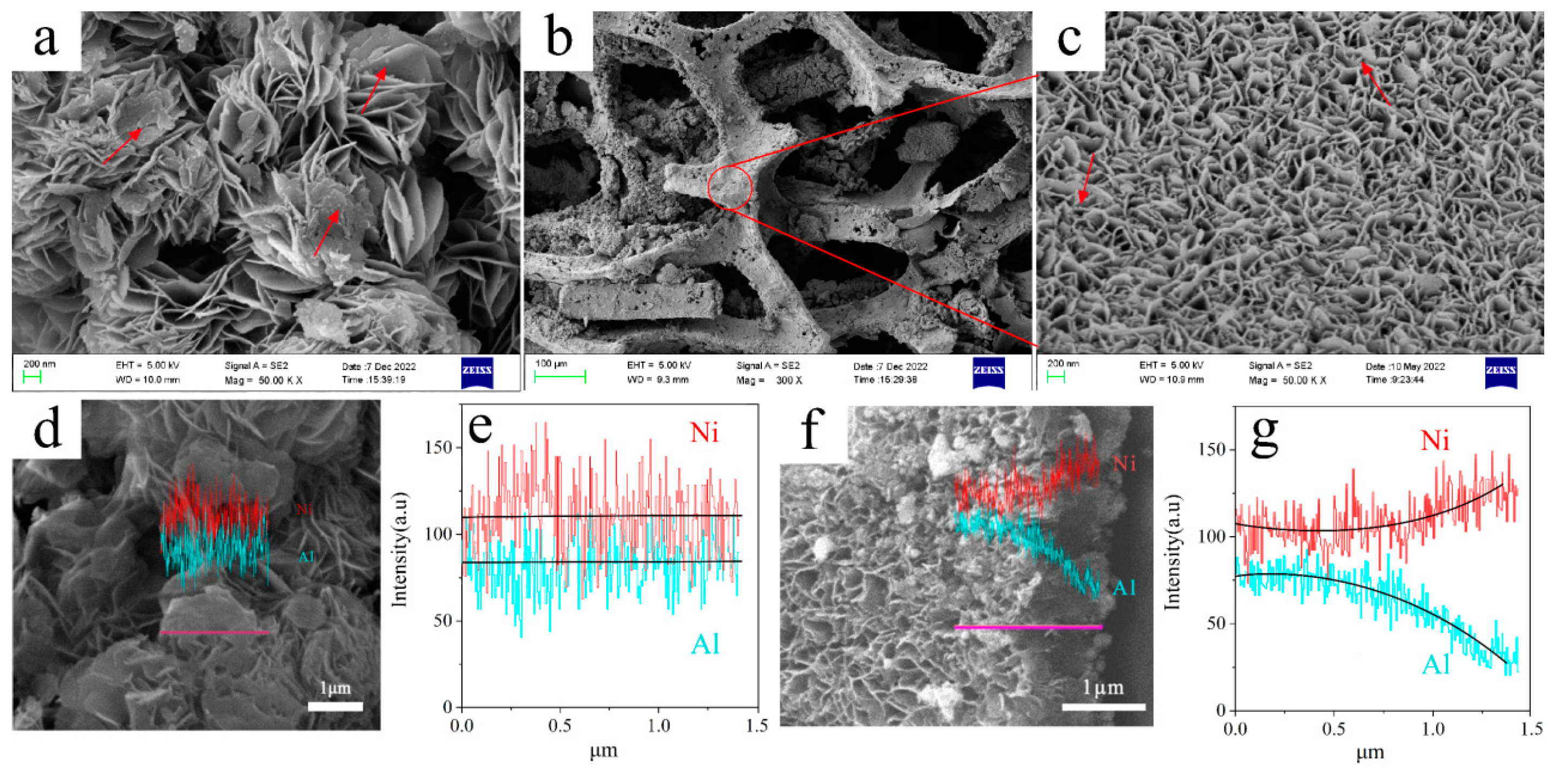
The corresponding morphology and structure of the as-synthesized NiAl powder and NiAl/NA catalysts were investigated using SEM. As shown in Figure 2a,c, both of the two catalysts maintained their precursor morphologies well after the pyrolysis treatment. The nanosheet surface of the NiAl powder catalyst became rough and porous, which might be attributed to the release of H2O and CO2 gases from the brucite layer, and to intercalated carbonate decomposition [19]. Moreover, spherical particles with an average grain size of 12.6 nm (red arrow in Figure 2a) were formed, which can be attributed to the Ni0 particles, according to the results of XRD. For the NiAl/NA catalyst, significant distinct morphological features were observed from the low and high magnification SEM images in Figure 2b,c. A uniform nanosheet with an average diameter of about 861 nm and thickness of about 26 nm assembled in an orderly manner into a three-dimensional mesh structure on the surface of the nickel foam. On the nanosheet’s surface, it is difficult to distinguish Ni0 nanoparticles, perhaps due to their small grain size. This probably results from the synergistic restraint effects of the 2D interlayer space and the metal substrate from the aggregation of metal oxide particles, which would facilitate the exposure of more active sites [28]. A detailed composition analysis using SEM line scan (Figure 2d–g) illustrated that Ni and Al species are homogeneously dispersed in NiAl powder. In contrast, the concentration gradient distributions of Ni and Al from the bottom to the top were revealed in the NiAl/NA catalyst, in which the Ni:Al ratio decreases from 5.2:1 to 1.4:1. This result demonstrates a Ni enrichment at the bottom of nanoarray-LDH, similar as that reported by Zhou [29]. Such a gradient doping may promote the generation of an electron transfer trend in active oxygen species, which finally promotes the reducibility of Ni species; this observation is consistent with our XRD results.
XPS measurement was adapted to further determine the elements and valence of the synthesized Ni–Al catalysts. The Ni and O elements were detected on the surface of the samples, and the results are shown in Figure 3. The shapes of the Ni 2p peaks are highly complicated due to spin-orbit doublets and satellite peaks. Two broad peaks at binding energies of ca. 880.3 eV and 862.2 eV correspond to the satellite peak of Ni2+. In the Ni 2p3/2 region of NiAl/NA catalysts, the peak at the binding energy of 856.8 eV could be attributed to the Ni3+ species, and the peak at 853.6 eV corresponds to Ni2+ in the phase [30]. For Ni2p1/2 spectra, two deconvoluted peaks at binding energies of 874.2 and 872.1 eV can be indexed to Ni3+ and Ni2+, respectively [31]. The Ni0 characteristic peak located at 851.9 eV is significantly large, indicating that the active Ni component can be reduced at a lower temperature in the NiAl/NA catalyst [32]. In the case of the NiAl powder catalyst, the characteristic peak intensity of Ni3+ is much weaker, and the Ni0 species is negligible. More interestingly, in the binding energy of Ni2+, a positive shift of 1.1 eV in the NiAl/NA catalyst emerged, implying the electron-rich structure of Ni atoms. The high-resolution spectrum of O1s is shown in Figure 3b. The O species at 528.9 eV were assignable to the typical metal–oxygen (M−O) bonds in LDHs, and that at 532.6 eV can be ascribed to adsorbed free O–O bonds at the material’s surface [33]. The increased intensity of adsorbed O–O in the NiAl/NA catalysts suggested the enhanced binding strength of its surface to oxygenated intermediates [34]. Moreover, the peak at 531.1 eV probably belonged to a high number of oxygen vacancies (Ov), which is attributed to the breaking of Ni–O bonds [35]. It should be noted that the oxygen vacancies are favorable for decreasing the adsorption energy of intermediates and facilitating their desorption of active sites [20]. The peak shifts of Ni2p and O1s indicate the existence of electronic coupling, which is probably because of the interaction between NiAl nanosheets and Ni foam substrate [29].
The N2 adsorption-desorption technique was used to evaluate the specific surface area and pore size distribution of as-synthesized NiAl powder and NiAl–NA catalysts (Figure 4). According to the IUPAC classification, the adsorption isotherms for both Ni–Al catalysts fit the type IV pattern, indicating the presence of a mesoporous structure [19]. The shape of the hysteresis loop could be classified as H3 type, revealing the slit pores that are associated with plate-like non-rigid particle aggregates with lamellar structure [10]. Nevertheless, the BET surface areas and pore volumes of the NiAl–NA catalysts are 197 m2/g and 0.55 cm3•g−1, respectively, which are almost two times of that of the NiAl powder (97 m2/g and 0.27 cm3•g−1). Moreover, the pore sizes for the two Ni–Al catalysts exhibited a similar distribution between 3 nm and 20 nm, as shown in the inset of Figure 4. These results indicate that the nanoarray construction on Ni foam substrate can prevent the agglomeration of nanosheets and expose more active sites for adsorption [20].

2.2. Evaluating the Catalytic Performance for Glycerol Steam-Reforming

The catalytic activities of as–prepared NiAl powder and NiAl/NA catalysts in the GSR process were investigated at 650 °C. As a comparison, a blank test without a catalyst and using Ni foam was also performed. Figure 5 shows the results based on the average H2 yield (YH2), the yield of carbon-containing products, and glycerol conversion to gaseous products (Xg) for 3 h on stream. Obviously, the introduction of the catalyst helped to promote the conversion of glycerol as well as the yield of gaseous products. For glycerol reforming without and with the Ni foam catalyst, a lower average glycerol conversion (Xg = 24.8%) with CO as the main gas product (yield of 20.5%) was obtained, which mainly resulted from the decomposition of glycerol. Through the introduction of the NiAl catalyst, the reforming of glycerol and the water–gas shift reactions were significantly enhanced. Regarding the gas products’ distribution, higher YH2 (85.4% vs. 74.7%), YCO2 (58.2% vs. 48.6%) and Xg (83.1% vs. 67.9%), as well as lower YCO (17.6% vs. 12.8%) were obtained for the NiAl/NA catalyst compared to the NiAl powder. To be precise, the actual amount of active components in the NiAl/NA catalyst was calculated to be only 0.26 g/g (0.26 g NiAl nanosheet versus 0.74 g Ni skeleton), which is only 26 wt.% compared to that used in the experiment with the NiAl powder catalyst. Considering that negligible activity was shown by the Ni foam skeleton, it could be concluded that the NiAl/NA catalyst had the much superior activity. This can be attributed to its small Ni0 nanoparticles, promoted reducibility, and large surface area and pore volume. Moreover, the low CO content and negligible CH4 in the products are beneficial for prolonging the catalyst’s life through suppression of coke formation from CO disproportionation and CH4 decomposition reactions [3].
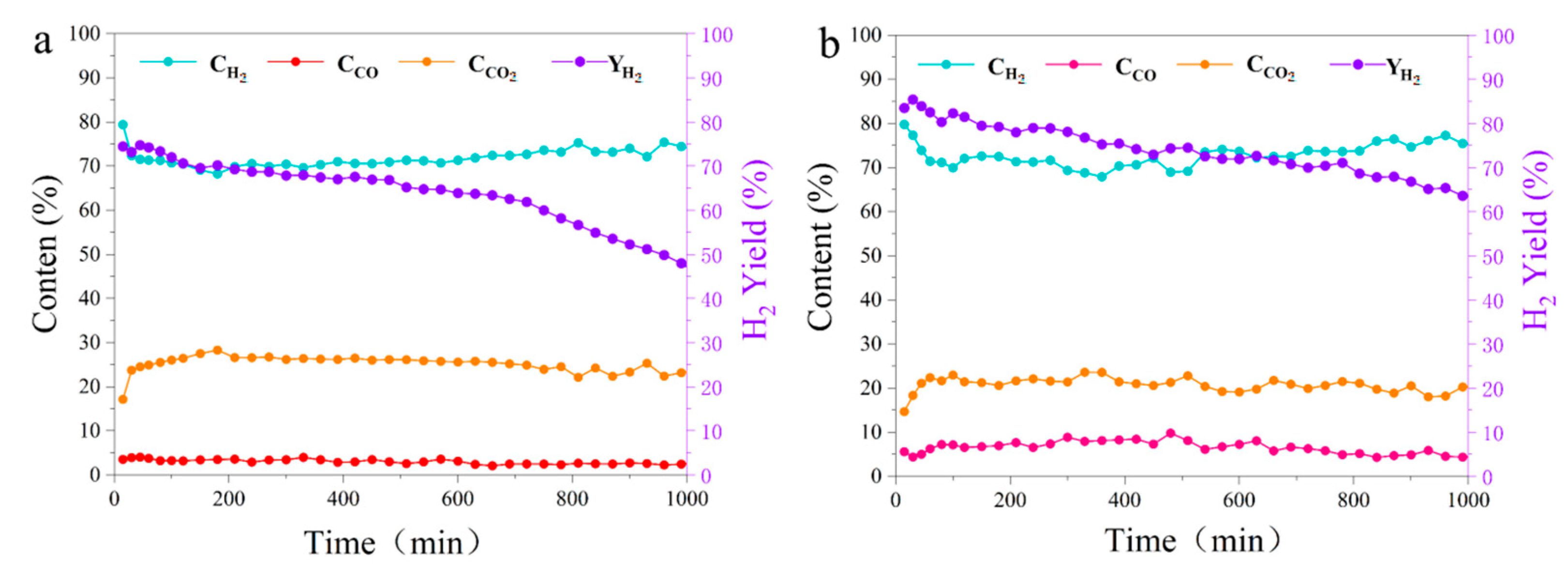
Long-term stability without deactivation is also a crucial factor for the practical application of catalysts. Figure 6 showed the contents of the gas product and H2 yield versus the reaction time over the NiAl powder and NiAl/NA catalysts. Obviously, high H2 contents of almost 70% were maintained for these two catalysts within 1000 min, which is close to the theoretical H2 content calculated from the equilibrium constant. As shown in Figure 6a, an obvious sign of deactivation was observed in the experiment with the NiAl powder catalyst, after a reaction lasting 480 min. The H2 yield decreased sharply from an initial level of 75.2% to 47.6% at the end, showing a decrease of 27.6% which might be attributed to the deactivation of catalyst by carbon deposits. On the contrary, the H2 yield of the NiAl/NA catalysts was more than 70% within an initial 700 min, which gradually decreased to 63.6% at the end of the experiment (Figure 6b), indicating their stable activity. That is to say, the array construction of the NiAl nanosheet on the Ni foam substrate not only improved the activity of the catalyst, but also extended its life by resisting coke formation, which was further characterized using TG techniques.

2.3. Characterization of the Coke Species in the Spent Catalysts

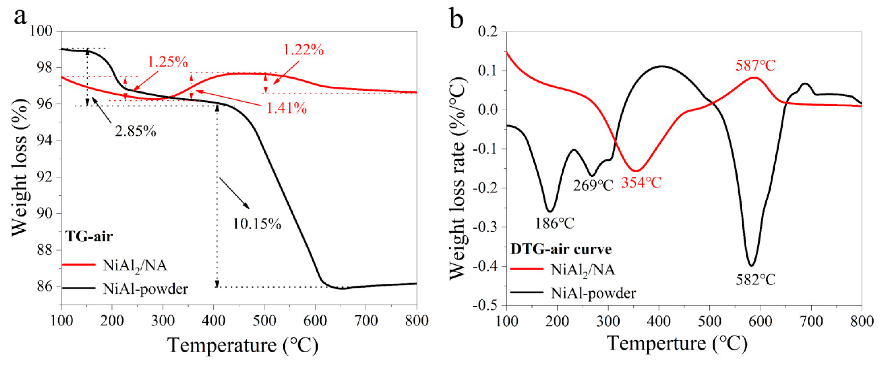
The coke deposition usually takes place on the catalyst during alcohol reforming reactions, which further has negative influences on the catalytic activity. TG and DTG analyses were employed to evaluate the amount and type of coke deposition on the surface of the spent NiAl powder and NiAl/NA catalysts. The weight loss curves were recorded and gathered in Figure 7a,b. It can be observed that the NiAl powder catalyst has two phases of drastic weight loss. The small decline during the initial heating below 300 °C was due to the removal of amorphous carbonaceous materials and volatiles that are prone to oxidation. The drastic weight loss started at ca. 430 °C, which was induced by the oxidation of highly ordered carbon [16]. In terms of coke amount, the weight loss of amorphous carbon was calculated to be 2.85%, and the ordered carbon amount was 10.15%. This indicated that the surface carbon of the NiAl powder catalyst was mainly made up of highly ordered carbon. From the TG and DTG curves of NiAl/NA catalyst, a negligible weight decline (only 1.25%) was observed, with only one weak peak assigned to the oxidation of amorphous carbonaceous materials and volatiles below 300 °C. Moreover, the weight showed an upward trend in the T range of 325–530 °C, and the mass gain was about 1.41%. As reported in the literature, this can be attributed to the integration oxidation of the deposited amorphous carbons and metallic Ni0 in the spent catalyst [36]. However, it is difficult to distinguish the oxidation peaks of coke and Ni species from each other. The results herein indicate that the NiAl/NA catalyst is beneficial for inhibiting the formation of coke (which causes catalyst deactivation); these results are consistent with its catalytic performance.
The properties of the coke formed over the two NiAl catalysts were further characterized using SEM and Raman. The morphologies of the spent catalysts are displayed in Figure 8a,b. Over the NiAl powder catalyst, a large amount of carbonaceous materials were formed after the reaction, which can be attributed to the high activity of metallic nickel species in cracking the C–O bonds in glycerol. For the reacted NiAl/NA catalyst, there was no obvious carbon deposition; meanwhile, plenty of spherical particles with an average size of 26 nm were identified on the surface, which we can assume to be active metallic Ni0 particles. According to the XPS and SEM line scan results, gradient doping was formed from the bottom to the top, and active oxygen species were generated in the NiAl/NA catalyst. This may have enhanced steam dissociation, acting to release more O* (or hydroxyl groups) and consequently gasify carbon-containing intermediates during GSR for the suppression of coke deposition. Figure 8c shows the Raman spectra of the spent NiAl powder and NiAl/NA catalysts. Two scattering peaks appeared at ~1358 cm−1 and ~1586 cm−1, respectively, which correspond to the D and G peaks of the carbon material [37]. Typically, the D peak results from the vibration of amorphous carbon and the arrangement irregular microcrystalline carbon, and the G peak is generated by the vibration of the carbon material with sp orbital structure in the two-dimensional direction [38]. The intensity ratio of ID/IG is usually used to characterize the degree of graphitization of carbon materials. It can be seen from Figure 8c that a lower ID/IG ratio of 1.18 was obtained for the used NiAl powder catalyst, the surface carbon of which was mainly highly ordered carbon. The results were in agreement with those of TG and DTG.
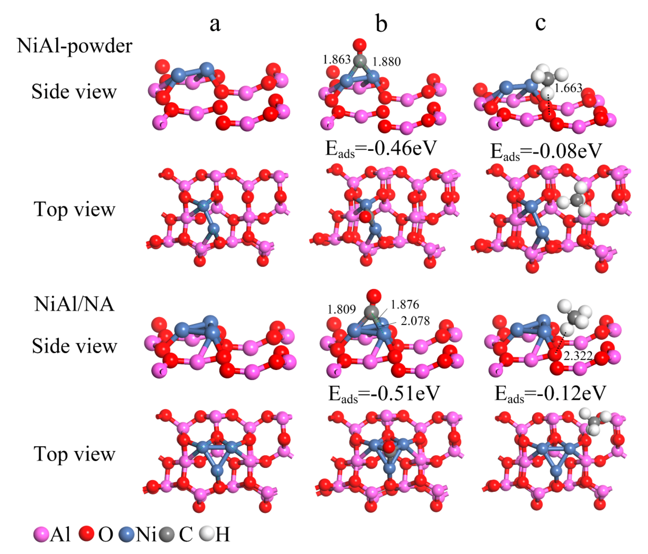
Generally, the formation of coke is very common during GSR, and carbon-containing gaseous products (CO, CH4 and CO2) can be coke precursors, according to the occurrence of CO disproportionation, CH4 decomposition and CO hydrogenation reactions [39]. Therefore, the adsorption and conversion behaviors of CO and CH4 in the products are crucial for catalyst deactivation. DFT was used to evaluate the ability of the two as-synthesized NiAl catalysts to adsorb CO and CH4 molecules, and the optimized geometry and adsorption energy are shown in Figure 9. It was found that the chemisorption of CO on the Ni (110) crystal plane occurred for both catalysts, with the adsorption energy calculated to be −0.51 eV and −0.46 eV, respectively. By contrast, the CH4 molecule was physically adsorbed on the surface of the two NiAl catalysts, with the adsorption energies calculated to be −0.12 eV and −0.08 eV, respectively. These results indicated the stronger interaction between CO and the NiAl powder catalyst. The carbon accumulation reaction on catalysts during the steam-reforming of glycerol is mainly driven by CO disproportionation.
Figure 10 depicts the energy barriers of CO disproportionation on the two as-prepared NiAl catalyst surfaces. The figure reveals that CO first dissociates into surface carbon and oxygen, both of which exhibit high activity. Subsequently, surface oxygen reacts with CO to generate CO2, and the most crucial step for carbon accumulation is the dissociation of CO. On the surface of the NiAl/NA catalyst, CO dissociation is required to overcome an energy barrier of 0.82 eV, which is much higher than that on the NiAl powder surface (0.51 eV). Therefore, carbon accumulation is resisted by the construction of a nanosheet array to prolong the life of the catalyst.

3. Materials and Methods

3.1. Catalysts Preparation

The NiAl–LDHs array precursor was prepared on a commercially available nickel foam using an urea homogeneous precipitation method [29]. In a typical procedure, CO(NH2)2 (0.012 mol) and Al(NO3)3•9H2O amounts (0.008 mol) were dissolved in 100 mL of deionized water to form a mixed solution. Two or three pieces of nickel foam with a diameter of 25 mm and a thickness of 1.5 mm were subjected to pre-treatment by immersion in 37 wt% concentrated HCl solution and sonication for 15 min to remove the surface nickel oxide. Subsequently, they were washed with deionized water and ethanol to eliminate residual acid. The mixed solution and nickel foam were transferred to a Teflon-lined stainless steel autoclave, which was sealed, maintained at 120 °C for 12 h, and then allowed to cool to room temperature naturally. A green metal substrate was formed and subsequently washed with deionized water with the assistance of ultrasonication. The resulting NiAl–LDHs array precursor was dried at 80 °C overnight and designated NiAl–LDHs/NA. As a reference, a traditional NiAl–LDHs precursor without metal substrate was also synthesized via urea hydrolysis, as described in our previous work [19]. A mixed solution containing 0.01 mol Al(NO3)3•9H2O, 0.04 mol of Ni(NO3)2•6H2O, and 0.2 mol of CO(NH2)2 in 100 mL deionized water was obtained. After being stirred at 95 °C for 24 h, filtered, washed with deionized water and dried, the disordered NiAl–LDHs powder was collected.
Afterward, the two NiAl–LDHs precursors were heated in a furnace at 650 °C for 2 h, under a continuous flow (100 mL min−1) of 10%H2/90%N2 gas. The resulting nanocomposites derived from NiAl–LDHs/NA and traditional NiAl–LDHs precursors were denoted NiAl/NA and NiAl powder, respectively.

3.2. Catalysts Characterization

The crystalline phases of the NiAl–LDHs precursors and derived catalysts were analyzed using X-ray power diffraction measurements (XRD) with a Rigaku D/max–IIIAX diffractometer with Cu Ka radiation (operating at 40 kV and 40 mA). The scan range of 2θ was 10–90°, with a scanning speed of 0.02/s. The crystallite size was estimated using Scherrer’s equation.
The morphologies and nanostructures of the fresh and used NiAl catalysts were investigated using a ZEISS SUPR 55 scanning electron microscope (SEM). Prior to SEM analysis, the samples were subjected to a gold-coating process.
The valence states of the NiAl catalysts’ surfaces were characterized using X-ray photoelectron spectroscopy (XPS). The XPS measurements were performed using a Thermo Fisher Scientific ESCALAB Xi+ spectrometer, equipped with a monochromated Al–Kα X-ray source. The instrument was operated in constant energy mode, with a passage energy of 100 eV and a step size of 1 eV.
The specific surface area and pore volume of the catalysts were analyzed using an automatic specific surface area and pore size distribution tester (JW–BK132F) from Beijing Jingwei Gao Bo Company. The sample (approximately 200 mg) was subjected to vacuum treatment at 200 °C overnight before measurement. Nitrogen was employed as the adsorption gas at a temperature of −196 °C.
The coke formed on the surface of used NiAl catalysts was analyzed using a PerkinElmer STA 8000 Thermogravimetric Analyzer (USA). For this analysis, 30 mg of the sample was subjected to heating from ambient temperature to 800 °C under an air atmosphere (30 mL/min) at a ramp rate of 10 °C/min, and held for a duration of 10 min.

3.3. Computational Detail

In this study, the electronic structure calculations were performed utilizing VASP software, based on the density functional theory (DFT) plane wave pseudopotential method [40]. The Perdew–Burke–Ernzerhof (PBE) method, incorporating the generalized gradient approximation (GGA), was employed to describe the exchange-correlation interactions among electrons [41]. The calculations incorporated the spin degree of freedom and utilized a plane wave basis set with a cut-off energy of 450 eV. The Brillouin zone was sampled using the Gamma method, with an automatically generated grid. The electrons’ self-consistent energy converged to a tolerance of 1 × 10⁻⁵ eV, and the interatomic interaction force converged to 0.1 eV/Å during the structure optimization. The transition state was calculated utilizing the climbing image nudged elastic band (CI–NEB) method, and a frequency analysis was conducted to confirm the presence of a single imaginary frequency [42]. Other parameters were assigned default values, as specified by the software package.
In this work, an Al2O3 model was selected as the support layer, with cell parameters of a = 11.26 Å, b = 11.78 Å, and c = 20.83 Å, and a vacuum layer of 15 Å [43]. The slab consisted of five O–Al layers, with the bottom two layers being frozen, while the remaining layers were optimized. A total of 2–3 Ni atoms were placed on the support layer [44]. The geometric structure optimization was performed with a convergence control on maximum residual force of less than 0.02 eV/Å. The adsorption energy (Eads) of the reaction was calculated using the following formula:
E ads   = E adsorbat + E substrate E adsorbtae   system
Here, Eads is the adsorption energy, and Eadsorbate and Esubstrate denote the energy of the adsorbed material and the energy of the catalyst surface, respectively. Eadsorbtae system denotes the energy of the system after adsorption.

3.4. Experimental Apparatus and Procedure

The performances of the as-obtained NiAl catalysts were evaluated in a fixed-bed system (as shown in Figure 11), which consists of an HPLC pump, a quartz tube reactor, a temperature controller, a condensation system, a gas sampling bag, and a product detector. Initially, 0.5 g of catalyst was placed in the center of quartz tube reactor and heated to 650 °C with a heating rate of 10 °C min−1 under 60 mL/min of N2 atmosphere. Afterward, glycerol solution with a concentration of 15 wt.% was introduced into the reactor at a flow rate of 0.05 mL/min, and the generated vapors were carried into a catalytic bed for reforming in the absence/presence of various catalysts. Finally, the released gaseous product after catalytic reforming passed through the condensing system, and was collected in sample bag for further analysis of its composition.

3.5. Products Analysis

The composition and yield of the as-obtained gas were determined using an Agilent 7890A gas chromatograph equipped with a thermal conductivity detector (TCD) and a flame ionization detector (FID). A molecular sieve column was used to separated the CO, H2, CH4, O2 and N2, while the CO2 was identified using another PoraPlot Q column. The gases yields were quantified using N2 as the internal standard. To ensure the accuracy of the results, each experiment was performed three times under the same reaction conditions, with the average value used for analysis.
The catalytic performance was evaluated as follows:
Glycerol conversion to gaseous products (Xg) was calculated based on a C atom balance in the gas phase:
x g ( % ) = n CO   + n CO 2   + n CH 4 3   × moles   of   glycerol   in   the   feed   ×   100
The yields of the carbon-containing species (Yi) in the gas phase products (i.e., CO, CO2 and CH4) were calculated based on the ratio of the moles of carbon in these gases, and the moles of carbon injected by glycerol in the inlet feed:
Y i = moles   of   C   in   specie   i 3   ×   moles   of   glycerol   in   the   feed   ×   100 %
where i represents CO, CO2, or CH4.
The concentrations of gas products are calculated as follows:
C i % = [ i ] H 2 + CO + CH 4 + [ CO 2 ]   ×   100 %
where i represents CO, CO2, or CH4.
The hydrogen yield (YH2) is calculated using the following formula:
Y H 2 % = moles   of   H 2   produced 7 × moles   of   glycerol   in   the   feed   × 100  
According to the stoichiometry of the GSR reaction, 7 mol H2 per mol of glycerol was considered the maximum theoretical yield of hydrogen.

4. Conclusions

In summary, innovative LDHs-derived NiAl nanosheet arrays (NiAl/NA) were successfully synthesized via a one-step hydrothermal method, and were proposed for enhanced and stable hydrogen production from the steam-reforming of glycerol in our work. Compared to traditional Ni–Al powder, smooth and cross-linked NiAl–LDHs nanosheets were orderly and perpendicularly grown on the nickel foam substrate, which significantly affects the Ni species’ particle size and porous structure. In particular, the distributions of Ni and Al concentration from the bottom to the top of the nanosheet were revealed using SEM line, which led to distinctly optimized Ni valence states and an optimized binding strength to oxygen species. The results of the glycerol-reforming experiments showed that the NiAl/NA catalyst showed an enhanced glycerol conversion (83.1%) and a higher H2 yield (85.4%), as well as longer stability (1000 min) compared to the traditional NiAl powder. This can be attributed to its improved reducibility, and more exposed active sites afforded by the unique array structures. According to the characterization results of spent catalyst and DFT calculation, the NiAl/NA catalyst effectively suppressed the coke formation, with only 1.25 wt.% of amorphous carbon deposition detected, which mainly formed from the CO disproportionation. Thus, the ease of preparation using a one-step hydrothermal method and the improved activity and resistance to carbon deposits of these LDHs-derived Ni-based nanosheet array catalysts make them promising for various other reactions.

Author Contributions

Conceptualization and design of experimental scheme, S.Y.; synthesis of catalyst, Y.L. and X.Y.; optimization of catalyst, L.C.; coke formation mechanism, G.X.; DFT calculation, J.H. and B.Z.; characterization of catalyst, L.S.; characterization results analysis, T.L.; analysis of catalyst performance, X.X.; coke characterization, H.S.; catalytic reforming experiment, D.H. All authors have read and agreed to the published version of the manuscript.

Funding

This work was financially supported by the Shandong Province Natural Science Foundation (No. ZR2022MB059), Jinan City’s “20 New Colleges and Universities” project (Nos. 202228018, 2021GXRC095) and the Disclosure project of Qilu University of Technology (Shandong Academy of Sciences) (No. 2022JBZ02–03).

Data Availability Statement

The authors state that the data pertaining to the manuscript will be made available upon request.

Acknowledgments

The authors extend their appreciation to Shandong Provincial Key Laboratory of Biomass Gasification Technology, Energy Research Institute, Qilu University of Technology (Shandong Academy of Sciences), Jinan.

Conflicts of Interest

There is no conflict of interest to declare.

References

  1. AlHumaidan, F.S.; Halabi, M.A.; Rana, M.S.; Vinoba, M. Blue hydrogen: Current status and future technologies. Energy Convers. Manag. 2023, 283, 116840. [Google Scholar] [CrossRef]
  2. Hermesmann, M.; Müller, T.E. Green, turquoise, blue, or grey? Environmentally friendly hydrogen production in transforming energy systems. Prog. Energy Combust. 2022, 90, 100996. [Google Scholar] [CrossRef]
  3. Roslan, N.A.; Abidin, S.Z.; Ideris, A.; Vo, D.V. A review on glycerol reforming processes over Ni-based catalyst for hydrogen and syngas productions. Int. J. Hydrogen Energy 2020, 45, 18466–18489. [Google Scholar] [CrossRef]
  4. Barreto, R.D.; Ramos, L.P.; Jorge, R.M.; Jorge, L.M. Turning glycerol surplus into renewable syngas through glycerol steam reforming over a sol-gel Ni–Mo2C–Al2O3 catalyst. Int. J. Hydrogen Energy 2023, 48, 16614–16629. [Google Scholar] [CrossRef]
  5. Umar, A.; Neagu, D.; Irvine, J.T. Renewable syngas & hydrogen synthesis via steam reforming of glycerol over ceria-mediated exsolved metal nano catalysts. Int. J. Hydrogen Energy, 2023; in press. [Google Scholar] [CrossRef]
  6. Schwengber, C.A.; Alves, H.J.; Schaffner, R.A.; Da Silva, F.A.; Sequinel, R.; Bach, V.R.; Ferracin, R.J. Overview of glycerol reforming for hydrogen production. Renew. Sustain. Energy Rev. 2016, 58, 259–266. [Google Scholar] [CrossRef]
  7. Zoppi, G.; Pipitone, G.; Pirone, R.; Bensaid, S. Aqueous phase reforming process for the valorization of wastewater streams: Application to different industrial scenarios. Catal. Today 2022, 387, 224–236. [Google Scholar] [CrossRef]
  8. Qingli, X.; Zhengdong, Z.; Kai, H.; Shanzhi, X.; Chuang, M.; Chenge, C.; Huan, Y.; Yang, Y.; Yongjie, Y. Ni supported on MgO modified attapulgite as catalysts for hydrogen production from glycerol steam reforming. Int. J. Hydrogen Energy 2021, 46, 27380–27393. [Google Scholar] [CrossRef]
  9. Dieuzeide, M.L.; Iannibelli, V.; Jobbagy, M.; Amadeo, N. Steam reforming of glycerol over Ni/Mg/γ–Al2O3 catalysts. Effect of calcination temperatures. Int. J. Hydrogen Energy 2012, 37, 14926–14930. [Google Scholar] [CrossRef]
  10. Sahraei, O.A.; Desgagnés, A.; Larachi, F.; Iliuta, M.C. A comparative study on the performance of M (Rh, Ru, Ni)–promoted metallurgical waste driven catalysts for H2 production by glycerol steam reforming. Int. J. Hydrogen Energy 2021, 46, 32017–32035. [Google Scholar] [CrossRef]
  11. Sanchez, E.A.; Comelli, R.A. Hydrogen by glycerol steam reforming on a nickel–alumina catalyst: Deactivation processes and regeneration. Int. J. Hydrogen Energy 2012, 37, 14740–14746. [Google Scholar] [CrossRef]
  12. Wang, Y.; Zhu, S.; Lu, J.; Liu, J.; Zhao, Y.; He, S.; Zhao, Y.; Lu, H.; Luo, Y. Boosting hydrogen production from steam reforming of glycerol via constructing moderate metal-support interaction in Ni@Al2O3 catalyst. Fuel 2022, 324, 124583. [Google Scholar] [CrossRef]
  13. Macedo, M.S.; Kraleva, E.; Ehrich, H.; Soria, M.A.; Madeira, L.M. Hydrogen production from glycerol steam reforming over Co-based catalysts supported on La2O3, AlZnOx and AlLaOx. Int. J. Hydrogen Energy 2022, 47, 33239–33258. [Google Scholar] [CrossRef]
  14. Macedo, M.S.; Soria, M.A.; Madeira, L.M. Process intensification for hydrogen production through glycerol steam reforming. Renew. Sustain. Energy Rev. 2021, 146, 111151. [Google Scholar] [CrossRef]
  15. Moogi, S.; Lee, I.G.; Hwang, K.R. Catalytic steam reforming of glycerol over Ni–La2O3–CeO2/SBA−15 catalyst for stable hydrogen-rich gas production. Int. J. Hydrogen Energy 2020, 45, 28462–28475. [Google Scholar] [CrossRef]
  16. Jing, F.; Liu, S.; Wang, R.; Li, X.; Yan, Z.; Luo, S.; Chu, W. Hydrogen production through glycerol steam reforming over the NiCexAl catalysts. Renew. Energy 2020, 158, 192–201. [Google Scholar] [CrossRef]
  17. Wang, Y.; Zhu, S.; Lu, J.; He, S.; Lu, H.; Song, D.; Chen, D.; Luo, Y. Novel nanowire self-assembled hierarchical CeO2 microspheres loaded with nickel-based catalysts for hydrogen production from steam reforming of glycerol. Fuel Process. Technol. 2023, 243, 107677. [Google Scholar] [CrossRef]
  18. Jayaprakash, S.; Dewangan, N.; Jangam, A.; Das, S.; Kawi, S. LDH-derived Ni–MgO–Al2O3 catalysts for hydrogen-rich syngas production via steam reforming of biomass tar model: Effect of catalyst synthesis methods. Int. J. Hydrogen Energy 2021, 46, 18338–18352. [Google Scholar] [CrossRef]
  19. Yang, S.; Chen, L.; Sun, L.; Xie, X.; Zhao, B.; Si, H.; Zhang, X.; Hua, D. Novel Ni–Al nanosheet catalyst with homogeneously embedded nickel nanoparticles for hydrogen-rich syngas production from biomass pyrolysis. Int. J. Hydrogen Energy 2021, 46, 1762–1776. [Google Scholar] [CrossRef]
  20. Zhou, J.; Dou, Y.; Wu, X.Q.; Zhou, A.; Shu, L.; Li, J.R. Alkali-Etched Ni (II)-Based Metal–Organic Framework Nanosheet Arrays for Electrocatalytic Overall Water Splitting. Small 2020, 16, 1906564. [Google Scholar] [CrossRef] [PubMed]
  21. Zhou, J.; Dou, Y.; Zhou, A.; Shu, L.; Chen, Y.; Li, J.R. Layered metal–organic framework-derived metal oxide/carbon nanosheet arrays for catalyzing the oxygen evolution reaction. ACS Energy Lett. 2018, 3, 1655–1661. [Google Scholar] [CrossRef]
  22. Xie, W.; Li, H.; Cui, G.; Li, J.; Song, Y.; Li, S.; Zhang, X.; Lee, J.Y.; Shao, M.; Wei, M. NiSn atomic pair on an integrated electrode for synergistic electrocatalytic CO2 reduction. Angew. Chem. 2021, 133, 7458–7464. [Google Scholar] [CrossRef]
  23. Yang, S.; Wang, L.; Zhang, X.; Yang, W.; Song, G. Enhanced adsorption of Congo red dye by functionalized carbon nanotube/mixed metal oxides nanocomposites derived from layered double hydroxide precursor. Chem. Eng. J. 2015, 275, 315–321. [Google Scholar] [CrossRef]
  24. Zhou, F.; Pan, N.; Chen, H.; Xu, X.; Wang, C.; Du, Y.; Guo, Y.; Zeng, Z.; Li, L. Hydrogen production through steam reforming of toluene over Ce, Zr or Fe promoted Ni–Mg–Al hydrotalcite-derived catalysts at low temperature. Energy Convers. Manag. 2019, 196, 677–687. [Google Scholar] [CrossRef]
  25. Shen, M.; Zhao, G.; Nie, Q.; Meng, C.; Sun, W.; Si, J.; Liu, Y.; Lu, Y. Ni–foam-structured Ni–Al2O3 ensemble as an efficient catalyst for gas-phase acetone hydrogenation to isopropanol. ACS Appl. Mater. Interfaces 2021, 13, 28334–28347. [Google Scholar] [CrossRef]
  26. Palmer, S.J.; Frost, R.L.; Ayoko, G.; Nguyen, T. Synthesis and Raman spectroscopic characterisation of hydrotalcite with CO32− and (MoO4)2− anions in the interlayer. J. Raman Spectrosc. 2008, 39, 395–401. [Google Scholar] [CrossRef] [Green Version]
  27. Yang, S.; Zhang, X.; Chen, L.; Sun, L.; Zhao, B.; Si, H.; Xie, X.; Meng, F. Pyrolysis of sawdust with various Fe-based catalysts: Influence of support characteristics on hydrogen-rich gas production. J. Anal. Appl. Pyrolysis 2019, 137, 29–36. [Google Scholar] [CrossRef]
  28. Peng, L.; Xiong, P.; Ma, L.; Yuan, Y.; Zhu, Y.; Chen, D.; Luo, X.; Lu, J.; Amine, K.; Yu, G. Holey two-dimensional transition metal oxide nanosheets for efficient energy storage. Nat. Commun. 2017, 8, 15139. [Google Scholar] [CrossRef] [Green Version]
  29. Zhou, D.; Jia, Y.; Duan, X.; Tang, J.; Xu, J.; Liu, D.; Xiong, X.; Zhang, J.; Luo, J.; Zheng, L.; et al. Breaking the symmetry: Gradient in NiFe layered double hydroxide nanoarrays for efficient oxygen evolution. Nano Energy 2019, 60, 661–666. [Google Scholar] [CrossRef]
  30. Zhou, K.; Zhou, W.; Yang, L.; Lu, J.; Cheng, S.; Mai, W.; Tang, Z.; Li, L.; Chen, S. Ultrahigh-performance pseudocapacitor electrodes based on transition metal phosphide nanosheets array via phosphorization: A general and effective approach. Adv. Funct. Mater. 2015, 25, 7530–7538. [Google Scholar] [CrossRef]
  31. Feng, Y.; Chen, X.; Wang, H.; Li, X.; Huang, H.; Liu, Y.; Li, H. Durable and high performing Ti supported Ni0.4Cu0.6Co2O4 nanoleaf-like array catalysts for hydrogen production. Renew. Energy 2021, 169, 660–669. [Google Scholar] [CrossRef]
  32. Yan, W.; Bao, W.; Tang, Y.; Li, Y.; Zhang, J.; Zhao, H.; Li, J.; Yu, F. Enhanced CO hydrogenation performance via two-dimensional NiAl–layered double oxide decorated by SiO2 nanoparticles. Int. J. Hydrogen Energy, 2022; in press. [Google Scholar] [CrossRef]
  33. Xu, L.; Jiang, Q.; Xiao, Z.; Li, X.; Huo, J.; Wang, S.; Dai, L. Plasma-engraved Co3O4 nanosheets with oxygen vacancies and high surface area for the oxygen evolution reaction. Angew. Chem. 2016, 128, 5363–5367. [Google Scholar] [CrossRef]
  34. Tao, H.B.; Fang, L.; Chen, J.; Yang, H.B.; Gao, J.; Miao, J.; Chen, S.; Liu, B. Identification of surface reactivity descriptor for transition metal oxides in oxygen evolution reaction. J. Am. Chem. Soc. 2016, 138, 9978–9985. [Google Scholar] [CrossRef]
  35. Li, F.L.; Wang, P.; Huang, X.; Young, D.J.; Wang, H.F.; Braunstein, P.; Lang, J.P. Large-scale, bottom-up synthesis of binary metal–organic framework nanosheets for efficient water oxidation. Angew. Chem. 2019, 131, 7125–7130. [Google Scholar] [CrossRef]
  36. Liu, Y.; Yu, H.; Liu, J.; Chen, D. Catalytic characteristics of innovative Ni/slag catalysts for syngas production and tar removal from biomass pyrolysis. Int. J. Hydrogen Energy 2019, 44, 11848–11860. [Google Scholar] [CrossRef]
  37. Dang, C.; Yang, W.; Zhou, J.; Cai, W. Porous Ni–Ca–Al–O bi-functional catalyst derived from layered double hydroxide intercalated with citrate anion for sorption-enhanced steam reforming of glycerol. Appl. Catal. B Environ. 2021, 298, 120547. [Google Scholar] [CrossRef]
  38. Lehman, J.H.; Terrones, M.; Mansfield, E.; Hurst, K.E.; Meunier, V. Evaluating the characteristics of multiwall carbon nanotubes. Carbon 2011, 49, 2581–2602. [Google Scholar] [CrossRef]
  39. Koc, S.; Avci, A.K. Reforming of glycerol to hydrogen over Ni-based catalysts in a microchannel reactor. Fuel Process. Technol. 2017, 156, 357–365. [Google Scholar] [CrossRef]
  40. Kresse, G.; Furthmüller, J. Efficient iterative schemes for ab initio total-energy calculations using a plane-wave basis set. Phys. Rev. B 1996, 54, 11169. [Google Scholar] [CrossRef]
  41. Perdew, J.P.; Burke, K.; Wang, Y. Generalized gradient approximation for the exchange-correlation hole of a many-electron system. Phys. Rev. B 1996, 54, 16533. [Google Scholar] [CrossRef] [Green Version]
  42. Sheppard, D.; Xiao, P.; Chemelewski, W.; Johnson, D.D.; Henkelman, G. A generalized solid-state nudged elastic band method. J. Chem. Phys. 2012, 136, 74103. [Google Scholar] [CrossRef] [Green Version]
  43. Liu, J.C.; Ma, X.L.; Li, Y.; Wang, Y.G.; Xiao, H.; Li, J. Heterogeneous Fe3 single-cluster catalyst for ammonia synthesis via an associative mechanism. Nat. Commun. 2018, 9, 1610. [Google Scholar] [CrossRef] [PubMed]
  44. Chang, Z.; Liu, Z.; Wang, C.; Li, J.; Zeng, J.; Liu, Y.; Zhang, M.; Li, J.; Yu, F. Three-dimensional porous Mn–Ni/Al2O3 microspheres for enhanced low temperature CO hydrogenation to produce methane. Int. J. Hydrogen Energy 2021, 46, 7912–7925. [Google Scholar] [CrossRef]
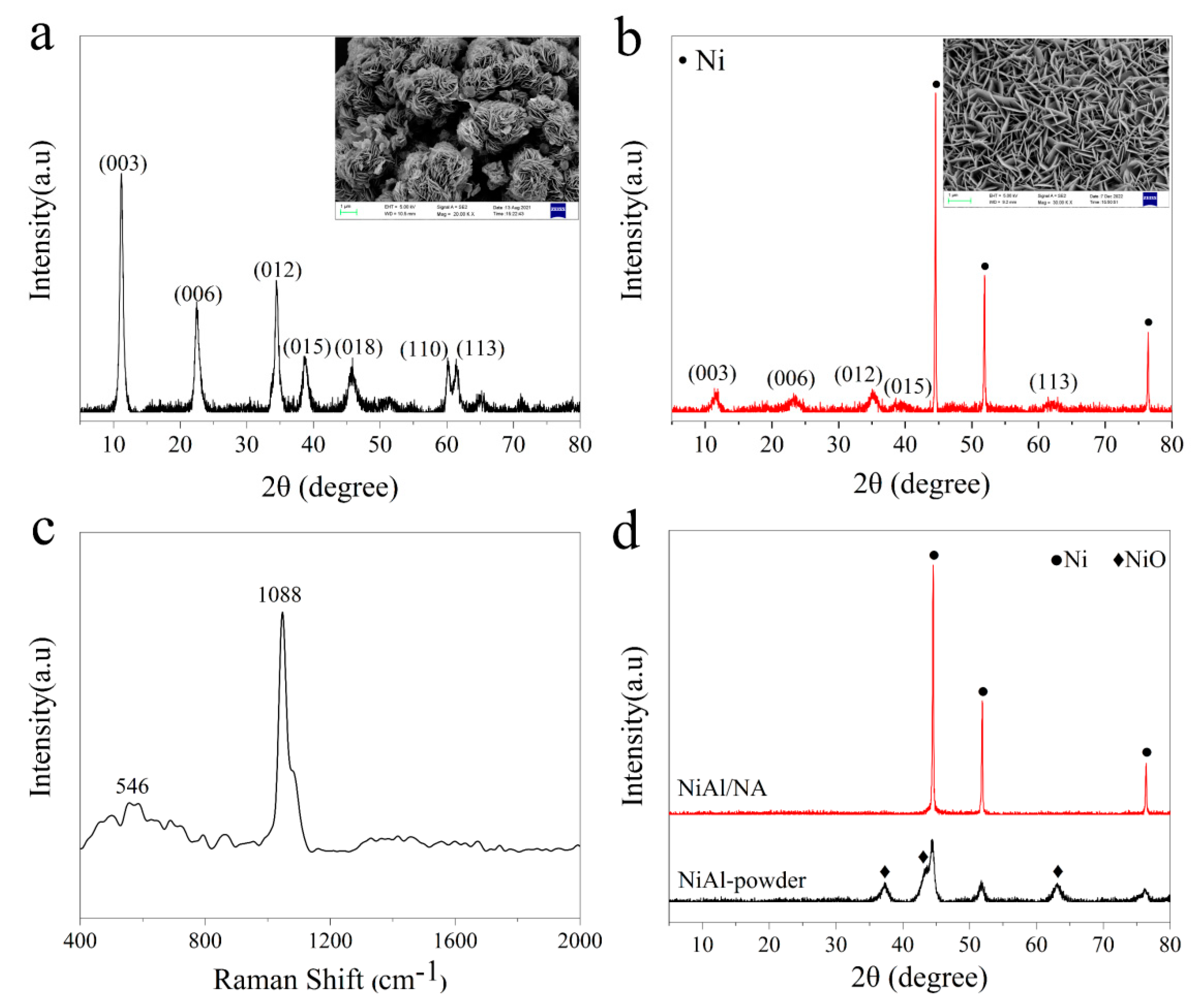
Figure 1. XRD patterns and SEM images (inset) of (a) NiAl–LDHs powder and (b) NiAl–LDHs/NA. (c) Raman spectrum of NiAl–LDHs/NA precursor and (d) XRD patterns of fresh NiAl catalysts derived from different precursors.
Catalysts 13 01047 g001
Figure 2. SEM images and line scan results of (a,d,e) NiAl powder and (b,c,f,g) NiAl/NA catalysts.
Catalysts 13 01047 g002
Figure 3. Comparison of XPS spectra of (a) Ni2P (b) O1s for NiAl powder and NiAl/NA catalysts.
Catalysts 13 01047 g003
Figure 4. N2 adsorption-desorption isotherms and pore size distributions (inset) of (a) NiAl powder and (b) NiAl/NA catalysts.
Catalysts 13 01047 g004
Figure 5. GSR performances of NiAl powder and NiAl/NA catalysts (a) H2 yield (b) CO2 yield (c) CO yield and (d) glycerol conversion to gaseous products.
Catalysts 13 01047 g005
Figure 6. The product yields in the GSR versus the prolonged reaction time over (a) NiAl powder and (b) NiAl/NA catalysts.
Catalysts 13 01047 g006
Figure 7. (a) TG and (b) DTG analyses of the spent NiAl powder and NiAl/NA catalysts.
Catalysts 13 01047 g007
Figure 8. (a,b) SEM images and (c) Raman spectra of the spent NiAl powder and NiAl/NA catalysts.
Catalysts 13 01047 g008
Figure 9. Side and top views of the most stable (a) original structure and adsorption structures of (b) CO and (c) CH4 molecules on the surface of NiAl powder and NiAl/NA catalysts.
Catalysts 13 01047 g009
Figure 10. Reaction energy barrier diagram for CO disproportionation on the surface of two NiAl catalysts.
Catalysts 13 01047 g010
Figure 11. Schematic diagram of the fixed-bed apparatus for hydrogen production from glycerol steam-reforming.
Catalysts 13 01047 g011
Disclaimer/Publisher’s Note: The statements, opinions and data contained in all publications are solely those of the individual author(s) and contributor(s) and not of MDPI and/or the editor(s). MDPI and/or the editor(s) disclaim responsibility for any injury to people or property resulting from any ideas, methods, instructions or products referred to in the content.