Article

Application of Ba0.5Sr0.5FeO3−δ-NdMnO3−δ Composite Cathode in Proton-Conducting Solid Oxide Fuel Cells

1
School of Materials Science and Engineering, Changchun University of Science and Technology, Changchun 130022, China
2
Key Laboratory of Functional Materials Physics and Chemistry of the Ministry of Education, Jilin Normal University, Changchun 130103, China
3
School of Materials Science and Physics, China University of Mining and Technology, Xuzhou 221116, China
*
Authors to whom correspondence should be addressed.
Catalysts 2023, 13(7), 1054; https://doi.org/10.3390/catal13071054
Submission received: 24 April 2023 / Revised: 28 June 2023 / Accepted: 28 June 2023 / Published: 29 June 2023

Abstract

:
Ba0.5Sr0.5FeO3−δ (BSF) nanofibers are prepared via electrospinning and sintering at a temperature of 800 °C for 2 h to produce a pure cubic perovskite phase, with the aim of finding a high-performance cathode material suitable for proton-conducting solid oxide fuel cells (PCFCs) operating at medium temperatures. The results of SEM analysis showed that the BSF nanofibers are alternately stacked, presenting fluffy and uniform high porosity, which is favorable to the cathode polarization reaction of PCFCs. To balance the excessive coefficient of thermal expansion of the BSF cathode, it is combined with a negative thermal expansion (NTE) material NdMnO3−δ (NM). At 700 °C, the peak power density (PPD) of the BSF–NM cathode cell is 1170 mW cm−2, and the open-circuit voltage (OCV) of the single cell is 1.04 V. The corresponding polarization impedance (Rp) of the BSF–NM is 0.037 Ω cm2. This result is significantly better than the previously reported powder cathode BSF, indicating that the performance of PCFC can be further optimized by transforming the BSF cathode into a nanofiber state and compounding it with the NTE material NM.

1. Introduction

Solid oxide fuel cells (SOFCs) are electrochemical conversion devices with high efficiency and low pollution, which are suitable for a wide range of fuels. The traditional oxygen ion conductor SOFCs operate at a high temperature, which limits the selection of electrode materials, resulting in high production and maintenance costs and hindering the large-scale commercial application of SOFCs [1,2]. Reducing the operating temperature of SOFCs to the medium range can effectively alleviate the above problems. At present, the commercialization of medium- and low-temperature SOFCs has made good progress. It is reported that the unit cell and stack products manufactured by the Elcogen Company not only have good performance, but also greatly reduce the cost [3]. In recent years, proton-conducting solid oxide fuel cells (PCFCs) have received more attention because of their medium operating temperature, low activation energy, and sufficient proton conductivity and stability [4,5]. During the operation of PCFCs, the polarization reaction of the cathode generates water, which will not dilute the fuel gas on the anode side [6]. A moderate operating temperature of PCFCs would enable a wider selection of electrode materials, especially cathode materials, which can prevent the need for the use of some precious metal raw materials, reduce costs, and avoid rapid thermal degradation of the electrode. Therefore, this work attempts to develop high-performance PCFCs at medium temperatures.
Stable and low ohmic impedance and low polarization impedance are the keys to developing high-performance PCFCs [7,8]. Anode-supported single cells allow the electrolyte layer to be prepared as a thin film. It has been reported that anode-supported single cells prepared based on standard materials can operate continuously and stably for 70,000 h [9]. Currently, the thin-film electrolyte technology has successfully been applied to reduce the ohmic resistance of a single cell and the influence of electrolyte material properties on single cells [10,11]. Therefore, the development of cathode materials with excellent electrochemical performance and stability is the hot topic of current research. According to the phase composition, the cathodes of PCFCs can be divided into two types: single-phase cathodes and complex-phase cathodes. Single-phase cathodes usually exhibit excellent mixed ionic–electronic conductivity (MIEC) and higher catalytic activity; examples include SrFe1−xTixO3−δ [12], La2NiO4+δ, LaNi0.6Fe0.4O3−δ [13], Ba0.5Sr0.5Co0.8−xFe0.2NbxO3−δ [14], and Sr3Fe1.8Co0.2O7−δ [15]. However, the high thermal expansion coefficient (TEC) of the single-phase cathode usually does not match that of the PCFC electrolyte [16], which considerably increases the interface impedance between the electrolyte and cathode, resulting in a decrease in the performance of the single cell. Usually, a composite cathode can be obtained by doping a certain proportion of electrolyte (proton conductor or ion conductor) into the cathode material. The TEC value of the composite cathode is moderately reduced, which improves the thermal matching between the cathode and the electrolyte, thereby improving the performance of the single cell. Examples include Sm0.5Sr0.5CoO3−δ-BaZr0.1Ce0.7Y0.2O3−δ [17], La0.7Sr0.3FeO3−δ-BaZr0.1Ce0.7Y0.2O3−δ [18], and Ba0.5Sr0.5FeO3−δ-Sm0.2Ce0.8O2−δ [19]. Compared with the single-phase cathodes, the TEC values of complex-phase cathodes are somewhat lower. However, due to the limited amount of doped electrolyte materials, the TEC of the composite cathode cannot be perfectly matched with the electrolyte material in most cases, which negatively affects the performance of the single cell. Therefore, it is essential to develop new methods to effectively improve the thermal matching between the cathode and the electrolyte.
The TEC values of some materials are negative within a certain temperature range; that is, they show heat contraction and cold expansion. This property was first discovered by Mary et al. in 1996. Since then, negative thermal expansion (NTE) materials have attracted the attention of researchers in related material fields [20]. To date, NTE materials can be divided into various types according to their structure and composition, including AB2O8 [20], AB2O7 [21,22], ABO3 [23,24], etc. Chao M. et al. invented a method of preparing NTE materials; they found that in the range of 20–740 °C, the average TEC value of NdMnO3 (NM) with a perovskite structure is −9.54 × 10⁻⁶ K−1, showing negative thermal expansion [25]. The MIEC material with an ABO3 perovskite structure is widely used in the cathodes of PCFCs. Therefore, in this work, the perovskite structure NTE material NM is doped in the single-phase MIEC cathode, thereby effectively reducing its high TEC.
Ba0.5Sr0.5FeO3−δ (BSF) is an efficient catalyst for oxygen reduction reaction, showing strong mixed conductivity, but especially a high TEC value. A composite cathode composed of BSF does not match the thermal properties of the electrolyte well but still has excellent electrochemical properties. Sun et al. applied a BSF–SDC composite cathode to PCFC with BaZr0.1Ce0.7Y0.2O3−δ (BZCY) electrolyte (mean TEC value: 10.1 × 10⁻⁶ K−1), and the single cell showed excellent peak power density (PPD) and a low polarization resistance (Rp) [19,26]. The average TEC of BSF at 100–800 °C was 27.09 × 10⁻⁶ K−1, which is quite high [27]. Therefore, the addition of SDC (average TEC value: 12.0 × 10⁻⁶ K−1) had a limited effect on the reduction in the TEC value of BSF. It is reported that the average TEC value of the BSF–NM composite at a 7:3 mass ratio is 9.98 × 10⁻⁶ K−1 at 100–800 °C, which is close to the TEC value of the electrolyte BZCY [27]. BZCY with a perovskite structure is easy to process, has high proton conductivity and good sinter ability, which makes it a good electrolyte material for PCFCs [28]. Because single-phase BSF cathodes and the NTE material NM have the same perovskite structure and good compatibility, this work applied unconventional composite cathode BSF–NMs to PCFCs with BZCY as the electrolyte.
In addition to the conductivity and oxygen reduction catalytic capacity determined by the material composition, the microstructure, morphology, and grain size of the cathode material are crucial to the performance of PCFCs. Electrospinning is a simple and feasible method for preparing one-dimensional filamentous nanomaterials [29,30,31]. Excellent electrochemical performance has been reported for single cells with one-dimensional nanostructured cathodes, such as La1−xSrxMnO3 [32], La1−xSrxCo1−yFeyO3−δ [33] and Sm0.5Sr0.5CoO3−δ [34]. During the operation of the PCFC, porosity is necessary for the diffusion of oxygen and the transport of carriers in the cathode material. The higher the porosity is, the smoother the transmission will be [35]. The nanoscale fibrous microstructure exhibits a looser and more uniform pore distribution than granular powder cathodes, which results in a more continuous and smoother transport of oxygen, ions and electrons, thus effectively reducing the concentration polarization. In addition, the porosity is directly related to TPB, which greatly affects the performance of PCFCs [35]. The nanofiber cathode provides more active three-phase interface reaction sites than the powder cathode, which effectively reduces the activation polarization. Therefore, in order to prepare cathode materials with superior oxygen reduction catalytic performance at medium temperatures and then improve the electrochemical performance of PCFCs, BSF was prepared in the nanofiber state, then compounded with the NTE material NM, and applied as a cathode material in the PCFC, to investigate its electrochemical performance.

2. Results and Discussion

2.1. X-ray Diffraction Analysis and Average Diameter of the BSF Fiber

The BSF/PVP composite fiber films were calcined at 700, 800, 900, and 1000 °C for 2 h, and the phase composition of the BSF fibers treated at 700–1000 °C was characterized by XRD. The heat treatment process is an important step in producing BSF nanofiber materials with a perovskite structure. As shown in Figure 1a, when the sintering temperature is 800 °C or above, the BSF fibers are in the pure perovskite phase with no heterotopic phase. The intensity of the diffraction peaks increases with the increase in the heat treatment temperature.
To verify the chemical compatibility of BSF fibers and the NM powder, chemical compatibility experiments were conducted. As shown in Figure 1b, the phase structure of the BSF/NM mixture was determined by XRD analysis. The XRD patterns of BSF fibers and the NM powder prepared in the experiment are also shown in the figure. Only the typical peaks corresponding to the BSF and NM appear, and there are no other derivative characteristic peaks. All typical peaks can be indexed to the BSF (PDF#14-0180) and NM (PDF#72-0378). The results of the XRD analysis show that no byproducts are formed during the calcination process, indicating that the BSF cathode exhibited chemical compatibility with the negative thermal expansion material NM.
Figure 2a shows the average diameter histogram of BSF/PVP composite fibers prepared by electrostatic spinning. The figure is measured by ImageJ software, drawn and calculated by Origin software. The average diameter of the BSF/PVP composite fibers is about 155 nm. Figure 2b depicts the histogram of the average diameter of BSF fibers sintered at 800 °C for 2 h. From the figure, we found that the organic components of the BSF/PVP fibers were removed and the shrinkage occurred after calcination at 800 °C for 2 h. The average diameter is approximately 60 nm, reduced to the nanometer scale.

2.2. Scanning Electron Microscope Analysis

Figure 3 shows the SEM micro-photographs of BSF/PVP fibers and BSF fibers calcined for 2 h at 800, 900, and 1000 °C. In Figure 3a, the smooth and continuous fibers are disorderly and overlapped, resulting in a large number of pores, which can provide a large number of high-quality channels for the diffusion of oxygen at the cathode. Figure 3b shows the BSF nanofibers sintered at 800 °C for 2 h. The continuity and large porosity of the nanofibers are retained; only a small portion of the fibers show slight nodular morphology. The BSF nanofibers are cross-stacked, forming a porous and continuous network structure. This microstructure can produce a higher specific surface area and more porosity, providing more channels for efficient charge transfer. Therefore, the BSF nanofibers sintered at 800 °C for 2 h are suitable for the PCFC cathode material.
Figure 3c,d show the BSF/PVP composite fibers sintered at 900 and 1000 °C for 2 h, respectively. In Figure 3c, a large number of breakpoints and nodules is shown in the fibers, and the uniformity and porosity of nanofibers are seriously deteriorated. The nanofiber porous skeleton structure in Figure 3d is not present, which indicates that the porous skeleton structure of BSF nanofibers is intolerant to high temperature. High temperature leads to fiber agglomeration and a loss of the porous skeleton structure. BSF nanofibers sintered at 900 and 1000 °C are unsuitable for PCFC cathode materials.
Figure 4 shows the cross-sectional SEM images of the BSF–NM cathode and the single cell (Ni-BZCY|BZCY|BSF–NM). In Figure 4a, the BSF nanofibers appear in the form of short nanorods, because the BSF nanofibers and NM powder were magnetically stirred for several hours to ensure uniform mixing during the preparation of the composite cathode. After several hours of magnetic stirring, the long BSF nanofibers had shortened. Compared with long fibers, short nanofibers help to increase the contact density of composite cathodes and electrolytes, so that the connection between the two is closer. The short nanofibers were still disorderly and staggered, maintaining a large porosity, and the NM particles were evenly distributed among them, forming a skeleton structure. In Figure 4b, the three-layer structure of a single cell is shown, and the BZCY electrolyte is dense and closely connected to the anode and cathode. The thickness of the BZCY electrolyte was approximately 14 μm. Both the cathode and anode showed loose porosity; the nanofiber cathode especially exhibited higher and more uniform porosity and a smaller pore size, owing to the special microstructure of nanofibers, which are conducive to the diffusion of oxygen and the transport of ions and electrons [36,37].
In order to study the element distribution of the BSF–NM composite cathode, EDX analysis was carried out on the surface of the sintered sample. Figure 5 shows the EDX-mapping and element distribution of the BSF–NM composite cathode. The uniformly distributed Ba, Sr, Fe, Mn, Nb, O elements can be seen from the figure, which confirms that the elemental composition of the composite cathode is consistent with the expectation.

2.3. Electrochemical Performance Test and Analysis

Figure 6a shows the I-V and I-P curves of the single cell (Ni-BZCY|BZCY|BSF–NM) at 500–700 °C. At 500, 550, 600, 650, and 700 °C, the PPDs and OCVs of the single cells were 177, 298, 480, 807, and 1170 mW cm−2 and 1.1, 1.1, 1.08, 1.06, and 1.04 V, respectively. Figure 6b compares the PPDs in this study with the previously reported powder composite BSF–NM cathode and single-phase BSF cathode [27]. The histogram shows the marked advantage of the BSF–NM nanofiber composite cathode.
Table 1 compares the maximum power density of PCFCs with doped BaFeO3−δ-based cathodes. The electrolytes of single cells shown in the table are all BZCY. Clearly, the single cell prepared by the BSF–NM composite nanofiber cathode shows obvious advantages, and the reasons can be summarized as follows. In general, for PCFCs, the electrochemical polarization reaction on the cathode side is an oxygen reduction reaction (ORR), which is a heterogeneous catalytic process. The porous cathode is the catalyst; the oxidant gas is the reactant. Heterogeneous catalysis usually occurs in the following steps: (1) external diffusion of reactants, (2) chemical adsorption and dissociation of reactants, (3) internal diffusion of reaction products, and (4) external diffusion of reaction products [38]. In this study, the excellent PPDs and OCVs of the single cell are mainly attributed to the special microstructure of the nanofiber BSF–NM cathode and the high matching of the thermal properties of the composite cathode and the electrolyte. The ORR catalytic process of the cathode is specifically analyzed as: O2 diffuses to the outer surface of the porous cathode BSF–NM and is adsorbed on the cathode surface. Under the catalysis of the cathode, O2 obtains electrons transmitted by the external circuit and is reduced to O2−. O2− then enters the cathode, reaches the cathode and electrolyte interface under the electrical load, and reacts with H+ at the three-phase interface. The porous microstructure of the nanofiber cathode is particularly conducive to the diffusion and adsorption of oxygen. At the same time, as an efficient catalyst, the BSF nanofiber cathode has a high specific surface area and provides more active sites for the polarization reaction, which can effectively reduce the activation polarization of O2. The BSF–NM nanofiber cathode has a porous skeleton structure, which can provide an effective path for a carrier transport and effectively reduce concentration polarization.
The stability of the single cell with the BSF–NM cathode was tested for 40 h. The test was carried out at 600 °C and 0.5 V constant voltage. Figure 6c shows the current density of the single cell as a function of time. The result shows that the current density of the single cell is very stable during the 40-h stability test. It has been reported that the degradation in the cathode performance, especially the increase in polarization resistance at the interface between the cathode and electrolyte, is considered to be the main reason for the performance degradation of the anode-supported SOFC at medium and low temperatures [39,40]. The addition of 3% NTE material effectively reduces the excessive TEC of the BSF cathode. The perfect TEC matching of the composite cathode BSF–NM and the electrolyte BZCY makes the two combine more closely, thereby effectively reducing the interfacial polarization resistance. The experimental results show that the composite cathode BSF–NM is suitable for the cathode material of the PCFC, and the stability of the single cell is favorable.
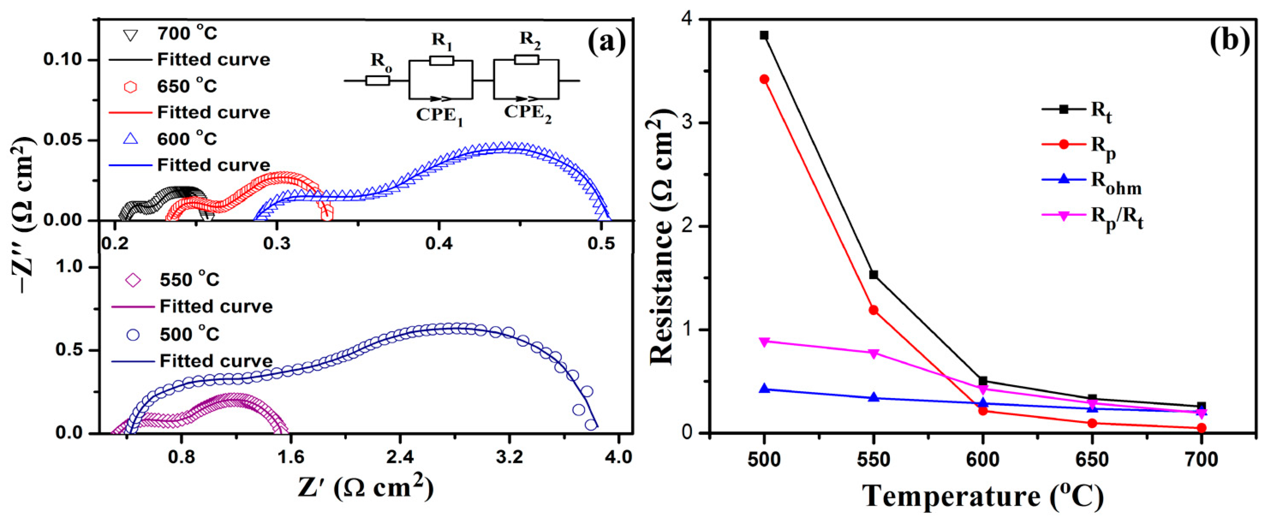
To investigate the factors affecting the output of the single cell, the electrochemical impedance spectrum at the open-circuit voltage was tested. The total resistance (Rt) of a single cell consists of the ohm resistance (Ro) and the polarization resistance (Rp). Ro mainly includes the proton resistance of the electrolyte and electrode, the transfer resistance of the proton, and the electronic resistance of the cell assembly. Rp is associated with the microstructure of the electrode and its catalytic properties. The high- and low-frequency intercepts of the real axis on the EIS curve represent the Ro and Rt of the single cell, respectively. The difference between Rt and Ro is the Rp of a single cell. Figure 7a displays the EIS curves of the single cells (Ni-BZCY|BZCY|BSF–NM) fitted with Zview software. In Figure 7a, each EIS curve consists of two semicircular arcs: a high-frequency and a low-frequency arc, which are related to the anodic polarization resistance (R1) and cathodic polarization resistance (R2), respectively.
To analyze the impedance of the single cell more intuitively, Figure 7b shows the curves of Rt, Ro, Rp, and Rp/Rt of the single cell as a function of temperature. As the operating temperature of the single cell increased, the Ro of the single cell decreased slightly, while the Rp of the single cell decreased rapidly. Specifically, as the temperature increased from 500 to 700 °C, the Rp decreased from 3.421 to 0.050 Ω cm2, and the Ro decreased from 0.425 to 0.207 Ω cm2. The decreasing rates of Rp and Ro with the increase in temperature are close, while the decreasing rate of Rp/Ro with the increase in temperature is much smaller, indicating that the main factor affecting the total impedance of the single cell is polarization impedance. In general, the Rp of PCFC is inversely proportional to the current density. Therefore, the low Rp of the single cell indicates that the nanofiber composite BSF–NM cathode has good catalytic activity for ORR during the single cell operation. At 700 °C, the lowest Rp of the BSF–NM cathode calculated from the fitting curve is 0.037 Ω cm2.
EIS fitting is commonly used to characterize the ASR of a single cell by the equivalent circuit model method, which can be specifically described as an equivalent circuit composed of appropriate circuit elements in different ways, such as series or parallels, to simulate the electrochemical characteristics of a specific system. As shown in Figure 7a, this work uses the equivalent circuit commonly used in EIS analysis for an anode-supported SOFC. Where Ro corresponds to the ohmic impedance, R1 corresponds to the polarization impedance in the high-frequency region, R2 corresponds to the polarization impedance in the low-frequency region, and RCT corresponds to the constant phase angle. Table 2 shows the Ro, R1, R2, Rp and Rt for a single cell at 500–700 °C extracted from the fitted curve in Figure 7a. The initial values corresponding to each component obtained experimentally are calculated in accordance with the equivalent circuit to obtain the impedance data corresponding to each component. The calculated results are compared with the experimental spectrum, and the component values are then adjusted and calculated and compared again. After several calculations and comparison processes, the difference between the calculated results and the experimental spectrum is finally minimized, and the optimized values of each element are obtained. The data of the fitted results are exported and then multiplied by the effective area to finally obtain the value of the ASR corresponding to each component. The calculation process is performed by Zview software. Taking the result of 700 °C as an example, the fitted result of Ro is 0.207 Ω. The effective area of the single cell in this work is 0.1 cm2. Therefore, the area-specific resistance of Ro is 0.207 Ω cm2.
The stable and low ohmic impedance can be attributed to the sufficient stability of the BZCY and the nanofiber structure and appropriate TEC value of the BSF–NM. The anode-supported single cell increases the structural stability of the single cell, and its electrolyte thin layer is only 14 μm, which greatly reduces the ohmic impedance of the single cell. Therefore, the single cell obtained a relatively stable low ohmic resistance over the entire test temperature range. Table 1 compares the lowest polarization resistance of PCFCs with doped BaFeO3−δ-based cathodes. The results show that the polarization resistance of a single cell with a nanofiber cathode in this work is much lower than that with a powder cathode. The larger specific surface area of the nanofiber cathode increases the active reaction sites at the three-phase interface of the cathodic polarization reaction. At the same time, the loose and porous microstructure of the nanofiber cathode provides a large number of effective pathways for the diffusion of oxygen and the transport of carriers, which accelerates the catalytic process of the cathodic polarization reaction. After the NTE material NM is doped in the BSF nanofiber cathode, the thermal expansion coefficient of the composite cathode is reduced to a perfect match with the BZCY, and the interfacial polarization impedance is also effectively reduced. The polarization process of the cathode can be summarized as the adsorption, dissociation, and diffusion of oxygen and any of these steps may affect the process of the polarization reaction. The low polarization resistance of the cathode is mainly attributed to the superior microstructure of the cathode material in the nanofiber state. The highly porous microstructure makes the gas diffusion and mass transfer smoother. The high specific surface area increases the length of the three-phase interface of the polarization reaction and promotes the polarization reaction process of the cathode.

3. Materials and Methods

3.1. Synthesis of Materials

Suitable concentrations of Ba(NO3)2, Sr(NO3)2, and Fe(NO3)3·9H2O were dissolved in organic solvents (DMF and PVP) to prepare the BSF spinning precursor solution. The spinning precursor solution was then placed into a 5 mL syringe with a 12-gauge needle and loaded into the electrospinning equipment. The preparation parameters were adjusted to a DC voltage of 15.5 kV and a receiving distance of 12–15 cm for electrospinning. To determine the phase formation temperature of the BSF, the BSF/PVP composite fiber membrane produced by electrospinning was calcined at 700–1000 °C for 2 h in the air atmosphere.
Mn2O3 and Nd2O3 were weighed according to a 1:1 molar ratio, and the mixed powder was ground for 1 h with an agate mortar, and then wet-ground for 1 h in the alcohol state, to ensure sufficient and uniform mixing. After the removal of the alcohol by evaporation, the mixed Mn2O3 and Nd2O3 powder was sintered at 1250 °C for 10 h to produce the negative thermal expansion substance NdMnO3−δ.
Chemical compatibility experiments were conducted on the BSF and NM. Specifically, the BSF and NM were mixed according to a mass ratio of 1:1, fully ground with an agate mortar until evenly mixed, and then the mixed powder was heat-treated at 1000 °C in an air atmosphere for 3 h to produce the BSF/NM mixed powder. The XRD was recorded to analyze the phase composition and determine whether the two materials showed chemical compatibility.

3.2. Preparation of Single Cells

The BSF nanofiber cathode material and the negative thermal expansion material (NM powder) were mixed, and then added to a 25 mL round-bottom flask at a mass ratio of 7:3. An appropriate amount of anhydrous ethanol was added to the flask, and the mixture was stirred for approximately 12 h. BSF nanofibers and NM powder were fully mixed in an ethanol solution, and an appropriate amount of ethyl cellulose pine alcohol solution containing 10% mass fraction was then added to the mixture as a binder. The mixed solution was magnetically stirred for approximately 4 h, and anhydrous ethanol was evaporated to produce a BSF–NM composite cathode slurry with appropriate viscosity.
The anode powder was composed of NiO, BZCY, and starch with a mass ratio of 3:2:1. With BZCY as the electrolyte material, the anode-supported half-cell was prepared following the co-pressed method. Specifically, an appropriate amount of anode powder was weighed with an electronic balance and loaded into a circular sheet mold. The anode powder was pressed into a sheet sample with a diameter of 1.2 cm under a static pressure of 200 MPa with a uniaxial tableting machine. A thin layer of BZCY electrolyte powder was co-pressed on the anode sheet to obtain an anode-supported half-cell co-pressed sheet. The co-pressed half-cell was then sintered at 1400 °C for 6 h. The Ni-BZCY|BZCY|BSF–NM single cells were obtained by coating the composite cathode slurry on the half-cell and sintering at 950 °C for 3 h. A mesh silver paste was coated on the electrode to collect the current, and a silver wire was used to conduct electricity. The single cell was sealed with silver paste and connected to one end of an alumina tube to produce the single cell to be tested. Figure 8 shows the detailed preparation process of the single cell in this work.

3.3. Characterizations and Electrochemical Properties

The phase characteristics of the BSF nanofibers, NM powder, and BSF–NM composite were analyzed by X-ray diffraction (XRD, Rigaku-D-Max YA, Tokyo, Japan). The morphology of BSF fibers before and after sintering at 800 °C, the surface of the BSF–NM composite cathode, and the cross-sections of single cells were observed with a scanning electron microscope (SEM, JEOL JSM-6480LV, Tokyo, Japan).
The I-V, I-P and EIS curves of the single cells were tested with an electrochemical workstation (CHI660C, Shanghai Chenhua, Shanghai, China). The temperature range of the test was 500–700 °C, and the frequency range was 0.01–105 Hz. Hydrogen was used as the fuel gas (10 mL/min) and air as the oxidant.

4. Conclusions

In this study, BSF nanofibers were prepared by the electrospinning method and then combined with the NET material NM. The former provided the required BSF microstructure, whereas the latter effectively reduced the high CET value of the BSF, making it perfectly matched with the thermal properties of the BZCY electrolyte, which considerably increased the electrocatalytic activity of the BSF cathode material and produced a superior single-cell performance at medium temperatures. The output of the PCFCs prepared by the BSF–NM composite cathode reached 1170 mW cm−2 at 700 °C, and the polarization resistance of the cathode was as low as 0.037 Ω cm2. The results show that the preparation of nanofiber cathode and its composite with NET materials can effectively optimize the microstructure of the cathode and reduce its high CET value. This work provides a simple, feasible and effective method to study single-phase cathodes with strong catalytic and mixed conductivity but extremely high CET values.

Author Contributions

C.S.: Investigation and writing—original draft preparation. Y.S., F.W. and F.J.: Writing—review and editing. Q.D.: Supervision. All authors have read and agreed to the published version of the manuscript.

Funding

This research was funded by the Department of Science and Technology of Jilin Province (grant number 20190303069SF, 20200201514JC).

Data Availability Statement

Not applicable.

Acknowledgments

This research is supported by Changchun University of Science and Technology and Jilin Normal University.

Conflicts of Interest

The authors declare no conflict of interest.

References

  1. Wang, S.; Shen, J.; Zhu, Z.; Wang, Z.; Cao, Y.; Guan, X.; Wang, Y.; Wei, Z.; Chen, M. Further optimization of barium cerate properties via co-doping strategy for potential application as proton-conducting solid oxide fuel cell electrolyte. J. Power Sources 2018, 387, 24–32. [Google Scholar] [CrossRef]
  2. Duan, C.; Tong, J.; Shang, M.; Nikodemski, S.; Sanders, M.; Ricote, S.; Almansoori, A.; O’Hayre, R. Readily processed protonic ceramic fuel cells with high performance at low temperatures. Science 2015, 349, 1321–1326. [Google Scholar] [CrossRef]
  3. Noponena, M.; Torria, P.; Göösa, J.; Puranena, J.; Kaara, H.; Pylypkob, S.; Roostarb, M.; Õunpuub, E. Elcogen–Next Generation Solid Oxide Cell and Stack Technology. ECS Trans. 2019, 91, 91–97. [Google Scholar] [CrossRef]
  4. Dai, H.; Da’as, E.H.; Shafi, S.P.; Wang, H. Tailoring cathode composite boosts the performance of proton-conducting SOFCs fabricated by a one-step co-firing method. J. Eur. Ceram. Soc. 2018, 38, 2903–2908. [Google Scholar] [CrossRef]
  5. Han, D.; Shinoda, K.; Sato, S.; Majima, M.; Uda, T. Correlation between electroconductive and structural properties of proton conductive acceptor-doped barium zirconate. J. Mater. Chem. 2015, A3, 1243–1250. [Google Scholar] [CrossRef] [Green Version]
  6. Xu, X.; Bi, L.; Zhao, X.S. Highly-conductive proton-conducting electrolyte membranes with a low sintering temperature for solid oxide fuel cells. J. Membr. Sci. 2018, 558, 17–25. [Google Scholar] [CrossRef]
  7. Medvedev, D.A.; Lyagaeva, J.G.; Gorbova, E.V.; Demin, A.K.; Tsiakaras, P. Advanced materials for SOFC application: Strategies for the development of highly conductive and stable solid oxide proton electrolytes. Prog. Mater. Sci. 2016, 75, 38–79. [Google Scholar] [CrossRef]
  8. Zhang, Z.; Chen, L.; Li, Q.; Song, T.; Su, J.; Cai, B.; He, H. High performance In, Ta and Y-doped BaCeO3 electrolyte membrane for proton-conducting solid oxide fuel cells. Solid State Ion. 2018, 323, 25–31. [Google Scholar] [CrossRef]
  9. Blum, L.; Haart, L.G.J.; Malzbender, J.; Margaritis, N.; Menzler, N.H. Anode-Supported Solid Oxide Fuel Cell Achieves 70,000 Hours of Continuous Operation. Energy Technol. Gener. Convers. Storage Distrib. 2016, 4, 939–942. [Google Scholar]
  10. Shao, Z.; Zhou, W.; Zhu, Z. Advanced synthesis of materials for intermediate-temperature solid oxide fuel cells. Prog. Mater. Sci. 2012, 57, 804–874. [Google Scholar] [CrossRef]
  11. Xu, X.; Xia, C.; Huang, S.; Peng, D. YSZ thin films deposited by spin-coating for IT SOFCs. Ceram. Int. 2005, 31, 1061–1064. [Google Scholar] [CrossRef]
  12. Mushtaq, N.; Xia, C.; Dong, W.; Abbas, G.; Raza, R.; Ali, A.; Rauf, S.; Wang, B.; Kim, J.; Zhu, B. Perovskite SrFe1−xTixO3−δ (x ≤ 0.1) cathode for low temperature solid oxide fuel cell. Ceram. Int. 2018, 44, 10266–10272. [Google Scholar] [CrossRef] [Green Version]
  13. Tang, H.; Jin, Z.; Wu, Y.; Liu, W.; Bi, L. Cobalt-free nanofiber cathodes for proton conducting solid oxide fuel cells. Electrochem. Commun. 2019, 100, 108–112. [Google Scholar] [CrossRef]
  14. Huang, Y.; Ding, J.; Xia, Y.; Miao, L.; Li, K.; Zhang, Q.; Liu, W. Ba0.5Sr0.5Co0.8−xFe0.2NbxO3−δ (x ≤ 0.1) as cathode materials for intermediate temperature solid oxide fuel cells with an electron-blocking interlayer. Ceram. Int. 2020, 46, 10215–10223. [Google Scholar] [CrossRef]
  15. Huan, D.; Shi, N.; Zhang, L.; Tan, W.; Xie, Y.; Wang, W.; Xia, C.; Peng, R.; Lu, Y. New, Efficient, and Reliable Air Electrode Material for Proton-Conducting Reversible Solid Oxide Cells. ACS Appl. Mater. Interfaces 2018, 10, 1761–1770. [Google Scholar] [CrossRef] [PubMed]
  16. Sun, C.C.; Shen, Y.; Wang, F.; Duan, Q. Nanofibrous La0.7Sr0.3FeO3−δ-SDC cobalt-free composite cathode for proton-conducting solid oxide fuel cell. Mater. Lett. 2023, 333, 133687. [Google Scholar] [CrossRef]
  17. Yang, L.; Zuo, C.; Wang, S.; Cheng, Z.; Liu, M. A novel composite cathode for low temperature SOFCs based on oxide proton conductors. Adv. Mater. 2008, 20, 3280–3283. [Google Scholar] [CrossRef]
  18. Sun, C.C.; Shen, Y.; Wang, F.; Duan, Q. Optimization of a Cobalt-free La0.7Sr0.3FeO3−δ-BaZr0.1Ce0.7Y0.2O3−δ composite cathode for proton-conducting solid oxide fuel cells. J. Alloys Compd. 2022, 923, 166447. [Google Scholar] [CrossRef]
  19. Sun, W.P.; Shi, Z.; Fang, S.; Yan, L.; Zhu, Z.; Liu, W. A high performance BaZr0.1Ce0.7Y0.2O3−δ-based solid oxide fuel cell with a cobalt-free Ba0.5Sr0.5FeO3−δ-Ce0.8Sm0.2O2−δ composite cathode. Int. J. Hydrog. Energy 2010, 35, 7925–7929. [Google Scholar] [CrossRef]
  20. Mary, T.A.; Evans, J.S.O.; Vogt, T.; Sleight, A.W. Negative thermal expansion from 0.3 to 1050 Kelvin in ZrW2O8. Science 1996, 272, 90–92. [Google Scholar] [CrossRef] [Green Version]
  21. Evans, J.S.O.; Hanson, J.C.; Sleight, A.W. Room-temperature superstructure of Zr2V2O7. Acta Crystallogr. 1998, B54, 705–713. [Google Scholar] [CrossRef] [Green Version]
  22. Wang, H.; Yang, M.; Chao, M.; Guo, J.; Gao, Q.; Jiao, Y.; Tang, X.; Liang, E. Negative thermal expansion property of β-Cu2V2O7. Solid State Ion. 2019, 343, 115086. [Google Scholar] [CrossRef]
  23. Oka, K.; Azuma, M.; Chen, W.T.; Yusa, H.; Belik, A.A.; Takayama-Muromachi, E.; Mizumaki, M.; Ishimatsu, N.; Hiraoka, N.; Tsujimoto, M.; et al. Pressure-induced spin-state transition in BiCoO3. J. Am. Chem. Soc. 2010, 132, 9438–9443. [Google Scholar] [CrossRef] [PubMed]
  24. Tang, X.; Jiao, Y.; Yang, M.; Chao, M.; Zhu, Y.; Chen, R.; Guo, J.; Gao, Q.; Liang, E. Anomalous thermal expansion properties in perovskite Sm0.85Zn0.15MnO3. Solid State Ion. 2020, 344, 115139. [Google Scholar] [CrossRef]
  25. Chao, M.; Li, Y.; Zhou, W.; Xiao, X.; Liu, Y.; Zhang, N.; Liang, E.; Li, Y.; Feng, D. Negative Thermal Expansion Material NdMnO3 and its Preparing Method. Chinese Patent CN104495942B, 25 January 2017. [Google Scholar]
  26. Miao, L.; Hou, J.; Gong, Z.; Jin, Z.; Liu, W. A high-performance cobalt-free Ruddlesden-Popper phase cathode La1.2Sr0.8Ni0.6Fe0.4O4+δ for low temperature proton-conducting solid oxide fuel cells. Int. J. Hydrog. Energy 2019, 44, 7531–7537. [Google Scholar] [CrossRef]
  27. Lu, F.; Yang, M.; Shi, Y.; Wu, C.; Jia, X.; He, H.; Su, J.; Chao, M.; Cai, B. Application of a negative thermal expansion oxide in SOFC cathode. Ceram. Int. 2021, 47, 1095–1100. [Google Scholar] [CrossRef]
  28. Hanif, M.B.; Rauf, S.; Abadeen, Z.; Khan, K.; Tayyab, Z.; Qayyum, S.; Mosiałek, M.; Shao, Z.P.; Li, C.X.; Motola, M.; et al. Proton-conducting solid oxide electrolysis cells: Relationship of composition-structure-property, their challenges, and prospects. Matter 2023, 6, 1782–1830. [Google Scholar] [CrossRef]
  29. Li, Q.; Sun, L.P.; Zhao, H.; Wang, H.L.; Huo, L.H.; Rougier, A.; Fourcade, S.; Grenier, J.C. La1.6Sr0.4NiO4 one-dimensional nanofibers as cathode for solid oxide fuel cells. J. Power Sources 2014, 263, 125–129. [Google Scholar] [CrossRef]
  30. Fan, L.Q.; Xiong, Y.P.; Liu, L.B.; Wang, Y.W.; Kishimoto, H.; Yamaji, K.; Horita, T. Performance of Gd0.2Ce0.8O1.9 infiltrated La0.2Sr0.8TiO3 nanofiber scaffolds as anodes for solid oxide fuel cells. J. Power Sources 2014, 265, 125–131. [Google Scholar] [CrossRef]
  31. Aruna, S.T.; Balaji, L.S.; Senthil Kumar, S.; Shri Prakash, B. Electrospinning in solid oxide fuel cells—A review. Renew. Sustain. Energy Rev. 2017, 67, 673–682. [Google Scholar] [CrossRef]
  32. Zhi, M.J.; Mariani, N.; Gemmen, R.; Gerdes, K.; Wu, N.Q. Nanofiber scaffold for cathode of solid oxide fuel cell. Energy Environ. Sci. 2011, 4, 417–420. [Google Scholar] [CrossRef]
  33. Zhi, M.; Lee, S.; Miller, N.; Menzler, N.H.; Wu, N. An intermediate-temperature solid oxide fuel cell with electrospun nanofiber cathode. Energy Environ. Sci. 2012, 5, 7066–7071. [Google Scholar] [CrossRef] [Green Version]
  34. Choi, J.Y.; Kim, B.S.; Shin, D.W. Performance evaluation of Sm0.5Sr0.5CoO3−δ fibers with embedded Sm0.2Ce0.8O1.9 particles as a solid oxide fuel cell composite cathode. J. Eur. Ceram. Soc. 2013, 33, 2269–2273. [Google Scholar] [CrossRef]
  35. Hanif, M.B.; Motola, M.; Qayyum, S.; Rauf, S.; Khalid, A.; Li, C.J.; Li, C.X. Recent advancements, doping strategies and the future perspective of perovskite-based solid oxide fuel cells for energy conversion. Chem. Eng. J. 2022, 428, 132603. [Google Scholar] [CrossRef]
  36. Sacanell, J.; Leyva, A.G.; Bellino, M.G.; Lamas, D.G. Nanotubes of rare earth cobalt oxides for cathodes of intermediate-temperature solid oxide fuel cells. J. Power Sources 2010, 195, 1786–1792. [Google Scholar] [CrossRef]
  37. Zhao, E.Q.; Ma, C.; Yang, W.; Xiong, Y.P.; Li, J.Q.; Sun, C.W. Electrospinning La0.8Sr0.2Co0.2Fe0.8O3−δ tubes impregnated with Ce0.8Gd0.2O1.9 nanoparticles for an intermediate temperature solid oxide fuel cell cathode. Int. J. Hydrog. Energy 2013, 38, 6821–6829. [Google Scholar] [CrossRef]
  38. Tahir, N.N.M.; Baharuddin, N.A.; Samat, A.A.; Osman, N.; Somalu, M.R. A review on cathode materials for conventional and proton-conducting solid oxide fuel cells. J. Alloys Compd. 2022, 894, 162458. [Google Scholar] [CrossRef]
  39. Hagen, A.; Barfod, R.; Hendriksen, P.V.; Liu, Y.L.; Ramousse, S. Degradation of Anode Supported SOFCs as a Function of Temperature and Current Load. J. Electrochem. Soc. 2006, 153, A1165–A1171. [Google Scholar] [CrossRef]
  40. Kim, J.W.; Virkar, A.; Fung, K.Z.; Mehta, K.; Singhal, S. Polarization Effects in Intermediate Temperature, Anode-Supported Solid Oxide Fuel Cells. J. Electrochem. Soc. 1999, 146, 69–78. [Google Scholar] [CrossRef]
  41. Cai, B.; Song, T.F.; Su, J.R.; He, H.; Liu, Y. Comparison of (Pr, Ba, Sr)FeO3−δ-SDC composite cathodes in proton-conducting solid oxide fuel cells. Solid State Ion. 2020, 353, 115379. [Google Scholar] [CrossRef]
  42. Ding, H.; Lin, B.; Liu, X.; Meng, G. High performance protonic ceramic membrane fuel cells (PCMFCs) with Ba0.5Sr0.5Zn0.2Fe0.8O3−δ perovskite cathode. Electrochem. Commun. 2008, 10, 1388–1391. [Google Scholar] [CrossRef]
  43. Zhao, L.; He, B.; Ling, Y.; Xun, Z.; Peng, R.; Meng, G.; Liu, X. Cobalt-free oxide Ba0.5Sr0.5Fe0.8Cu0.2O3−δ for proton-conducting solid oxide fuel cell cathode. Int. J. Hydrog. Energy 2010, 35, 3769–3774. [Google Scholar] [CrossRef]
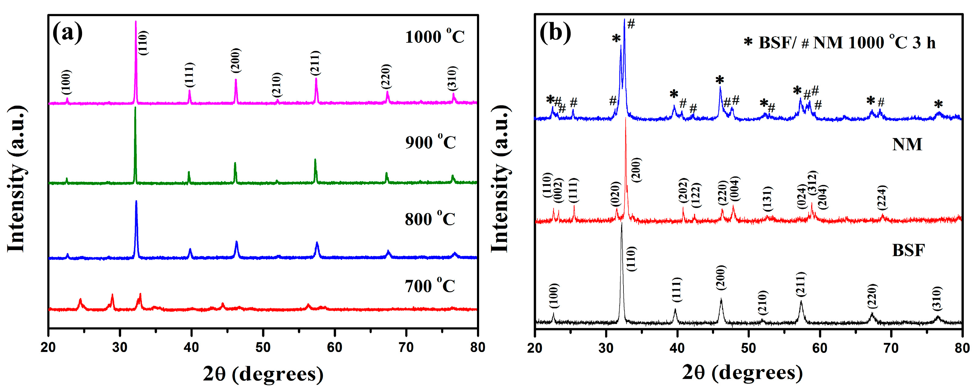
Figure 1. XRD patterns of: (a) BSF fibers calcined at 700–1000 °C; (b) BSF fibers, NM powder and BSF/NM mixture (1:1 mass ratio).
Catalysts 13 01054 g001
Figure 2. Average diameter histogram of: (a) BSF/PVP composite fibers; (b) BSF nanofibers sintered at 800 °C for 2 h.
Catalysts 13 01054 g002
Figure 3. SEM microphotographs of: (a) BSF/PVP fibers; (bd) BSF fibers calcined at 800, 900, and 1000 °C, respectively.
Catalysts 13 01054 g003
Figure 4. Cross-sectional SEM images of: (a) BSF–NM cathode; (b) single cells (Ni-BZCY|BZCY|BSF–NM).
Catalysts 13 01054 g004
Figure 5. The EDX-mapping and element distribution of BSF–NM composite cathode.
Catalysts 13 01054 g005
Figure 6. (a) I-V and I-P curves of Ni-BZCY|BZCY|BSF–NM at 500–700 °C; (b) PPDs of single cells with BSF–NM nanocathode, BSF–NM powder cathode, and BSF powder cathode at 500–700 °C. (c) The stability test of the single cell with BSF–NM cathode for 40 h at 600 °C.
Catalysts 13 01054 g006
Figure 7. (a) EIS curves of single cells fitted with Zview; (b) Rt, Rp, Ro and Rp/Rt of single cells as a function of temperature.
Catalysts 13 01054 g007
Figure 8. Schematic diagram of single-cell fabrication.
Catalysts 13 01054 g008
Table 1. Comparison of polarization impedance and maximum power density of doped BaFeO3−δ-based cathode single cell.
CathodeElectrolyteT (°C)Rp (Ω cm2)Pm (mW cm−2)Ref.
Ba0.5Sr0.5FeO3−δ-SDC powderBZCY7500.030792[19]
Ba0.5Sr0.5FeO3−δ powder BZCY7500.120661[27]
Ba0.5Sr0.5FeO3−δ-NdMnO3−δ powderBZCY7500.054941[27]
Ba0.5Sr0.5FeO3−δ-SDC powderBZCY7500.135657[41]
Pr0.5Ba0.25Sr0.25FeO3−δ-SDC powderBZCY7500.092811[41]
Ba0.5Sr0.5Zn0.2Fe0.8O3−δ powderBZCY7000.080486[42]
Ba0.5Sr0.5Fe0.8Cu0.2O3−δ-BZCY powderBZCY7000.160430[43]
BSF nanofiber-NM powderBZCY7000.0501170[this work]
Table 2. Rt, Ro, Rp, and R2 extracted from the EIS fitting curve at 500–700 °C.
T (°C)Ro (Ω cm2)R1 (Ω cm2)R2 (Ω cm2)Rp (Ω cm2)Rt (Ω cm2)
5000.425 ± 0.0141.072 ± 0.0632.349 ± 0.1553.4213.846
5500.339 ± 0.0190.360 ± 0.0490.829 ± 0.0731.1891.529
6000.287 ± 0.0170.047 ± 0.0050.169 ± 0.0150.2160.504
6500.235 ± 0.0110.028 ± 0.0020.068 ± 0.0070.0960.331
7000.207 ± 0.0080.013 ± 0.0020.037 ± 0.0030.0500.257
Disclaimer/Publisher’s Note: The statements, opinions and data contained in all publications are solely those of the individual author(s) and contributor(s) and not of MDPI and/or the editor(s). MDPI and/or the editor(s) disclaim responsibility for any injury to people or property resulting from any ideas, methods, instructions or products referred to in the content.