Article

Enhancing Nickel-Iron Gas Diffusion Electrodes for Oxygen Evolution in Alkaline Water Electrolysis

1
Institute of Chemical and Electrochemical Process Engineering, Clausthal University of Technology, 38678 Clausthal-Zellerfeld, Germany
2
Research Center Energy Storage Technologies, Clausthal University of Technology, 38640 Goslar, Germany
*
Author to whom correspondence should be addressed.
Catalysts 2023, 13(9), 1266; https://doi.org/10.3390/catal13091266
Submission received: 30 July 2023 / Revised: 25 August 2023 / Accepted: 28 August 2023 / Published: 1 September 2023

Abstract

:
Alkaline water electrolysis is a well-known technology for sustainable hydrogen production powered by renewable energy. The use of gas diffusion electrodes (GDEs) based on nonprecious materials eliminates the need for an anolyte cycle, leading to a cost reduction of the electrolysis process. In this work, the production of GDEs made of nickel particles and different iron precursors is investigated for the improvement of the oxygen evolution reaction. The GDE production followed an established four-step process: dispersing, spraying, hot pressing, and sintering. Physical characterization comprised the determination of the pore size distribution by capillary flow porometry and mercury porosimetry, as well as BET surface area measurements. Electrochemical characterization through linear sweep voltammetry and EIS measurements was performed in a custom half cell. The results show that the overall performance of the GDE based on low-cost iron compounds was comparable to existing GDE formulations, while improvements could be achieved regarding the overpotential in the kinetic region. Nevertheless, future investigations concerning the gas purity and long-term stability of the GDEs will be the next steps of the electrode development.

1. Introduction

The development of sustainable green hydrogen production is an important task for the future. This aspect is emphasized by the reports of the International Energy Agency (IEA) and Hydrogen Council, which predict a hydrogen demand of 500 Mt [1], with an overall revenue of approximately 3 trillion USD in 2050 [2] for the net-zero plan. Currently, about 95% of the currently used hydrogen is produced by fossil sources [3], mainly natural gas (grey hydrogen), leading to CO2 emissions of up to 14 kg per kg hydrogen [4]. Hence, it is crucial to reduce sustainable hydrogen production costs to compete with the price tag of grey hydrogen to achieve the net-zero plan target CO2 emissions. Generally, hydrogen production by electrolysis does not emit primary CO2 as long as renewable electrical energy is used, but the costs have to be optimized. This can be achieved by lowering the overpotentials, which are dominated by the oxygen evolution reaction (OER) [5,6], as well as by improved electrode and stack designs [7].
The most mature variant among the different available technologies is alkaline water electrolysis (AEL) [8]. AEL is generally considered to be more cost-effective than other technologies because no expensive precious metal catalysts are required [9]. However, the efficiency of alkaline electrolysis can be increased by implementing high-performance catalysts, optimized commercial-scale cell designs, lifetime improvements, optimized process conditions, and an adequate combination with renewable energy sources [8,10,11,12,13,14].
AEL is typically operated with a concentrated potassium hydroxide electrolyte (25–32 wt.%) in a temperature range between 313 K and 363 K, and pressures up to 30 bar [8,9,11,15,16,17,18]. The cathode and the anode are separated by a porous separator or membrane (Figure 1a), which prevents mixing of the product gases and allows the hydroxide anions to pass through [8,16]. Since water is consumed at the cathode and produced at the anode, the electrolyte cycles are continuously mixed in state-of-the-art AEL to avoid too large concentration differences between the two half cells [11,15].
However, the mixing process contaminates the electrolyte with dissolved gases and diminishes the gas purity, limiting the part-load capacity of the AEL [13,18,19]. It has been shown that mixing can be the main gas contamination mechanism in AEL, and is more dominant than the permeation of gases through the separator [20]. In order to avoid electrolyte mixing, a novel hybrid AEL concept has been presented by Koj et al. [15]. The authors used a porous GDE as anode, a conventional nickel mesh as cathode, and a Zirfon™ separator in a zero-gap assembly (Figure 1b). Since only the catholyte cycle is present, the system complexity decreases and a higher gas purity can be expected. The main focus in this work was the improvement of the GDE for the OER, which is the main limiting step for the overall water splitting process [21], since the OER has sluggish reaction kinetics with much lower exchange current density compared to the fast hydrogen evolution reaction (HER) [22]. The reason for the sluggish reaction kinetics is the slow four-electron transfer and the formation of peroxide bonds [23,24].
GDEs consist of a hydrophobic, gas-permeable structure made of or coated with a hydrophilic catalyst material [14]. PTFE is a commonly used material for adjusting hydrophobicity [14,15,25,26]; this polymer forms the hydrophobic structure of the pores in the GDE, and keeps the gas and the electrolyte separated [14]. Thus, the mass transport inside the gas phase is not hindered by the electrolyte, which has a very poor solubility for the produced gases [14].
Two well-established electrochemical parameters for comparing the performance of different electrodes are the Tafel slope and electrode overpotential. A low Tafel slope value implies that the current density increases favorably at relatively low overpotentials. A typical value for stainless steel mesh (SSM) electrodes was reported by Zhang et al. [27], who reached a Tafel slope of 87 mV dec−1 for the OER (0.1 M KOH, room temperature). With a cathodization method, during which nickel is enriched on the surface and oxidized to Ni(oxy)hydroxide, these authors were able to improve the Tafel slope to 70 mV dec−1 under the same reaction conditions. The overpotential of this cathodized SSM was 319 mV at 100 mA cm−2. Another work showed that the Tafel slope of an SSM can be further decreased to 40 mV dec−1 (30 wt.% KOH, room temperature) by a sulfuration process [28]. This process, combined with an electrochemical treatment, transforms the surface of the SSM into a NiFe-based hydr(oxy)oxide surface, which is known as a highly active catalytic phase for the OER [21,29]. With this sulfurated SSM, the overpotential reached values of 307 mV at 100 mA cm−2. In contrast, Marini et al. [30] used different catalyst powders and a binder to generate a rubbery paste to produce NiFe and Co containing GDEs. These electrodes reached a Tafel slope of 55 mV dec−1, and an overpotential of 267 mV at 100 mA cm−2 (28 wt.% KOH, 298 K) [30].
As shown by Koj et al. [15], it is possible to produce GDEs from Ni particles and iron(II) acetate precursor, using a spraying and sintering process. With these GDEs, a Tafel slope of 57 mV dec−1 and an overpotential of 294 mV at 100 mA cm−2 (32 wt.% KOH, 293 K) was observed. Koj et al. assumed that NiFe-based hydroxy-oxides were formed during the polarization of the GDE, explaining the favorable Tafel and overpotential results. All of the above-mentioned works used nickel and/or NiFe-based catalysts, and achieved good electrochemical results. Furthermore, these two metals are widely available, Fe being particularly inexpensive, and their overpotential for the OER has an acceptable value for technical applications [31,32].
However, since iron(II) acetate is a relatively expensive Fe-compound (10.68 EUR g−1) [33], and not available in industrial quantities, the objective of the present work was to identify less costly Fe-precursor compounds with comparable or even better properties in the GDE. The critical properties for ensuring a feasible manufacturing process are water solubility and thermal decomposability of the organic precursor components. Consequently, two suitable Fe compounds were identified: iron(II) lactate (1–5 EUR kg−1, mean: 2.50 EUR kg−1) and iron(II) gluconate (2.50–9 EUR kg−1, mean: 4.26 EUR kg−1) for industrial bulk amounts between 200 and 10,000 kg. The price for laboratory quantities with comparable purity would be significantly higher (iron(II) lactate 0.32 EUR g−1 [34] and iron(II) gluconate 0.11–0.08 EUR g−1 [35]). Based on the selected precursors, the development of a new GDE formulation for the OER during hybrid AEL is presented. These findings can help to minimize the manufacturing costs, while preserving competitive characteristics of the GDE.

2. Results and Discussion

2.1. Physical Characterization

2.1.1. Optical Microscope

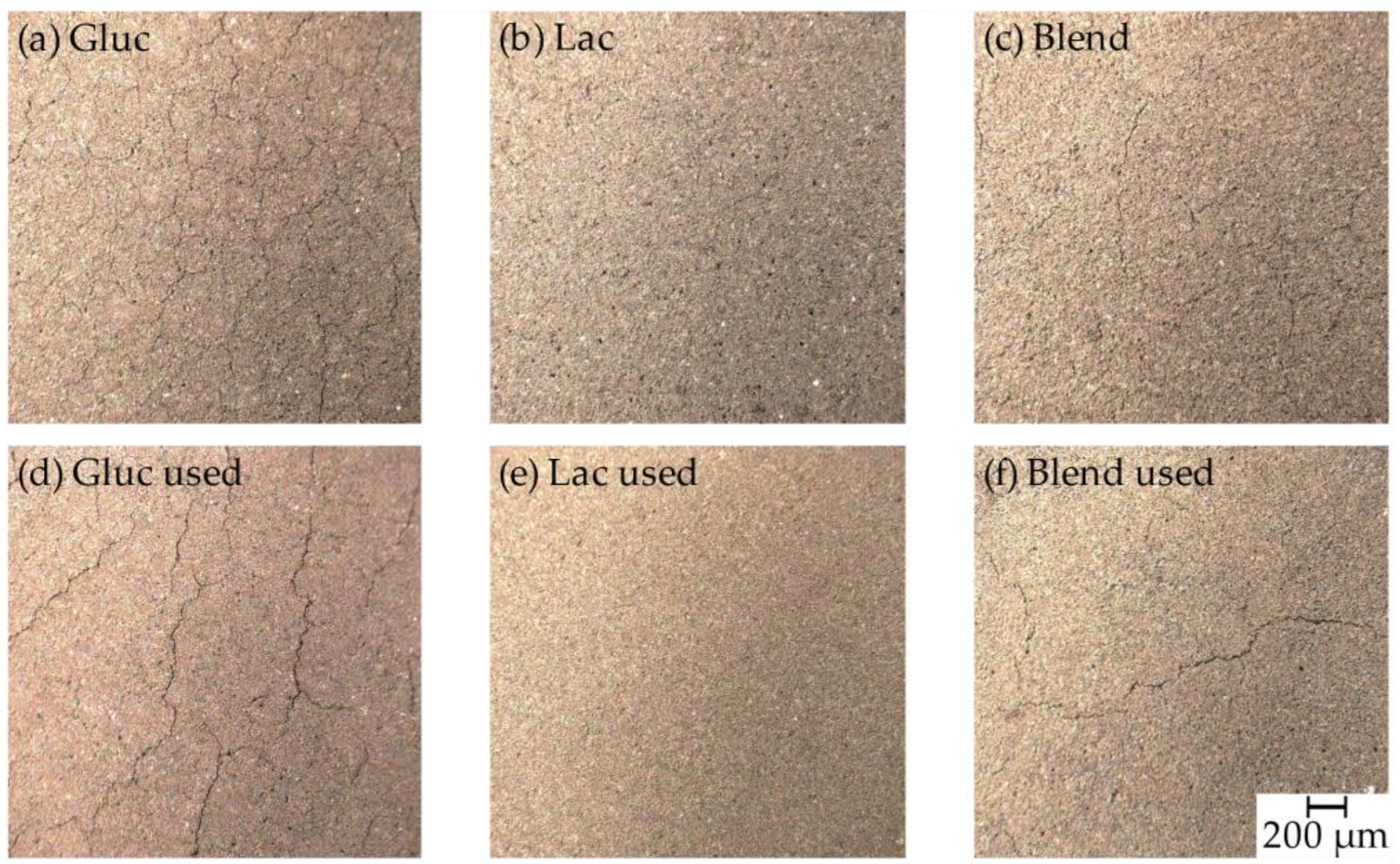
During the production of the three different GDEs, it was observed that the iron(II) gluconate (Gluc) GDE has a tendency to develop visible cracks on the surface after the sintering step, Figure 2a. These cracks show a gap size of approximately 40 µm and are not desirable because of a potential electrolyte breakthrough, which should be prevented. Moreover, the Gluc GDE is very brittle, making its handling difficult. In contrast, the iron(II) lactate (Lac) GDE did not tend to visible crack formation or brittleness, and the electrode was more flexible, Figure 2b. In addition, a combination of both iron precursors was used in an attempt to eliminate crack formation. This Blend GDE showed only a few thin cracks prior to electrochemical characterization, Figure 2c. Hence, GDEs without large cracks and reduced brittleness could be produced.
Closer inspection of the surface of the three different GDEs before and after the electrochemical characterization revealed certain differences. Figure 2e shows the Lac GDE after the electrochemical characterization, where no cracks were visible. In contrast, the Gluc GDE in Figure 2d shows numerous cracks on the surface after the electrochemical characterization. Those cracks have a gap size of approximately 7 µm. On the Blend GDE, Figure 2f, some cracks with a size of approximately 7 µm were visible, but to a lesser extent than on the Gluc GDE. A reason for the cracks could be the mechanical stress inside the half cell caused by the contact pressure or by the pressure exerted by evolving gas, which could break up the surface. These observations show that the addition of iron(II) gluconate to the precursor suspension tends to mechanically destabilize the GDEs, since cracks in the micrometer range were observed. In contrast, the addition of iron(II) lactate does not result in visible cracks, and when combining both iron sources, the cracks remain within an acceptable range. However, it has to be noted that ‘cracked mudflat’ surface morphologies are commonly found in sprayed catalyst layers, such as those for PEM fuel cells [36]. Moreover, cracks may also serve as preferred pathways either for electrolyte of gas transport, and could also have a beneficial impact on the performance of GDEs.

2.1.2. Pore Diameter and Surface Area

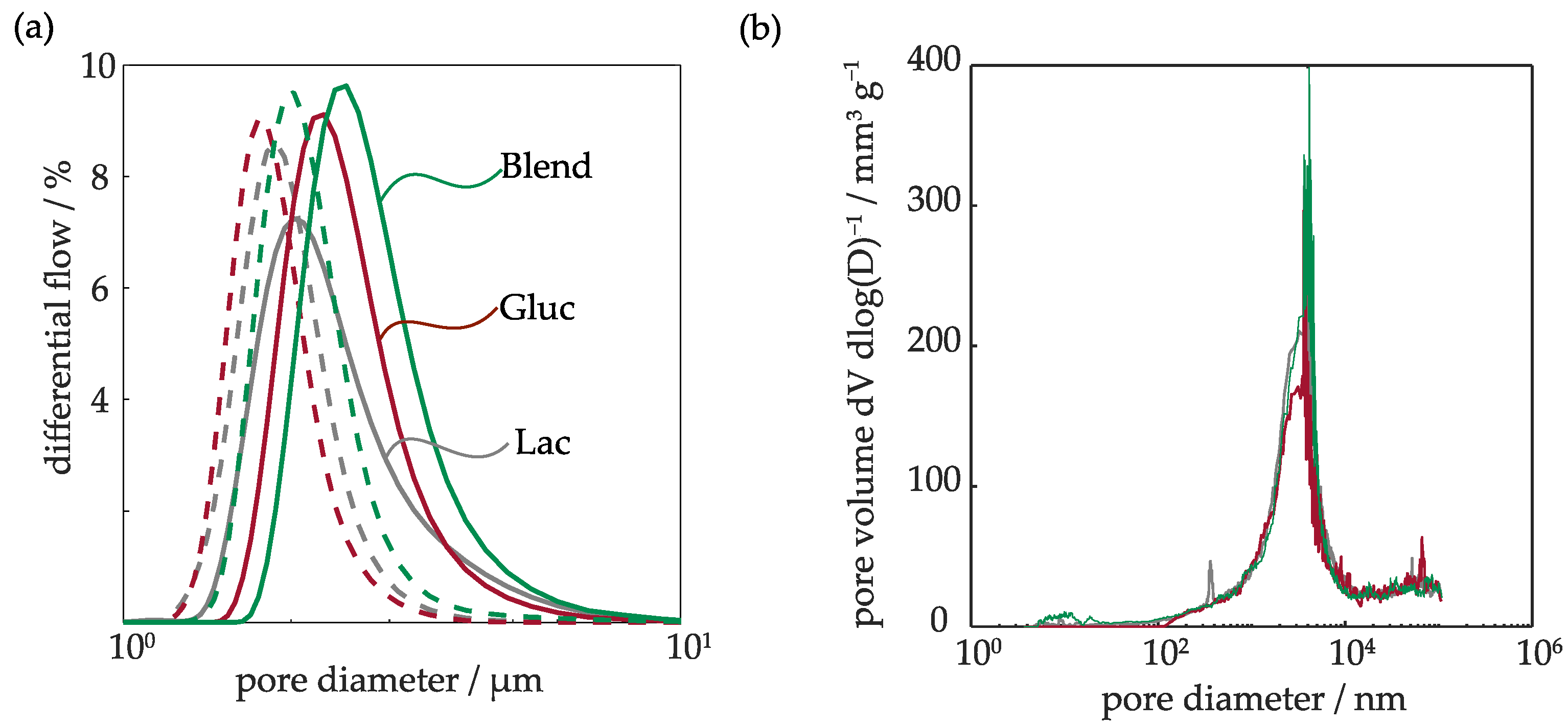
For the investigation of pores and internal surface area, examinations were carried out using a capillary porometer, mercury porosimetry, and BET surface measurements. Figure 3a shows the results of the flow-through porometry measurements before and after electrochemical testing, where the differential flow is depicted versus the pore diameter. It can be seen that the GDEs have slightly different pore size distribution, which can be explained by the characteristic size of the iron precursors as they decompose during the heat treatment. Since a constant iron content of 2 wt.% was maintained in all GDEs, the ratio of the different Fe compounds changes depending on their molecular weight. Thus, the spraying suspension contained more iron(II) gluconate (~14.3 wt.%) than iron(II) lactate (~7.4 wt.%) to reach the same amount of iron in the GDE. The Blend GDE contained approximately ~5 wt.% of iron(II) lactate and iron(II) gluconate each. Hence, different amounts of residue were removed during the sintering step. As a result, the Lac GDE has the smallest diameter of flow-through pores, followed by the Gluc GDE and Blend GDE.
As already mentioned, cracks were observed after the electrochemical experiments. To verify if those cracks extend throughout the entire structure of the GDE, additional flow-through porometry measurements were performed. It can be seen that the pore size distribution of all GDEs decreases after the experiments, Figure 3a. However, the shape of the curves remains very similar to the measurements of the pristine GDEs. This implies that a change of the porous matrix of the GDE has taken place. An explanation could be that KOH deposits, which partially block the pores, remain inside the GDE after being removed from the cell. During the mercury porosimetry measurement, a small region with nanopores can be identified, as shown in Figure 3b. However, no significant differences between the measured GDEs can be observed.
The results of the physical measurement results are summarized in Table 1. While all accessible pores down to approx. 2 nm diameter can be intruded with mercury porosimetry, only continuous pore paths are captured with flow-through porometry, which additionally also delivers the bubble point. Depending on the size of the bubble point, transport processes within the GDE can be affected, for example, by pore flooding [15]. The bubble points of the GDEs produced in this work, and the NiFeGDE2 investigated in earlier work [15], have a comparable value. Similarly, the mean flow-through pore diameter of the GDEs produced in this study is also comparable. However, a notable difference is evident when compared to the NiFeGDE2, which exhibits a smaller mean flow-through pore diameter. The comparison of pore volume and mean pore diameter from mercury porosimetry measurements reveals no significant differences.
The results of the BET surface area measurement results are also shown in Table 1. A comparison of the Lac, Gluc, and Blend GDE with the NiFeGDE2 from previous work shows that the BET surface area of the latter is about four times higher. This could be a result of the higher iron precursor residue. In the work of Koj et al. [15], it was assumed that the relatively high surface area results from nanometer-sized pores. However, nanometer pores were hardly observed in the GDEs produced in this work, Figure 3b, which explains the lower surface area compared to the NiFeGDE2. Overall, the newly produced GDEs show similar physical properties with only little differences among them.

2.2. Electrochemical Results

2.2.1. Linear Sweep Voltammetry

The GDEs required a stabilization period before working properly as they reached a full wetting of their active surface. In order to achieve full wetting, the extensive measurement sequence, consisting of one open circuit potential (OCP) measurement, 26 cyclic voltammetries (CV), three electrochemical impedance spectroscopy (EIS) measurements, one chronopotentiometry (CP) measurement at 10 mA cm−2, three linear sweep voltammetry (LSV) measurement, and a final CP measurement at 100 mA cm−2, was repeated three times; for further details refer to Section 3.4. It is interesting to note that no breakthrough of electrolyte or droplet formation was observed for all electrodes, and only a slightly moist surface was present after the experiments.
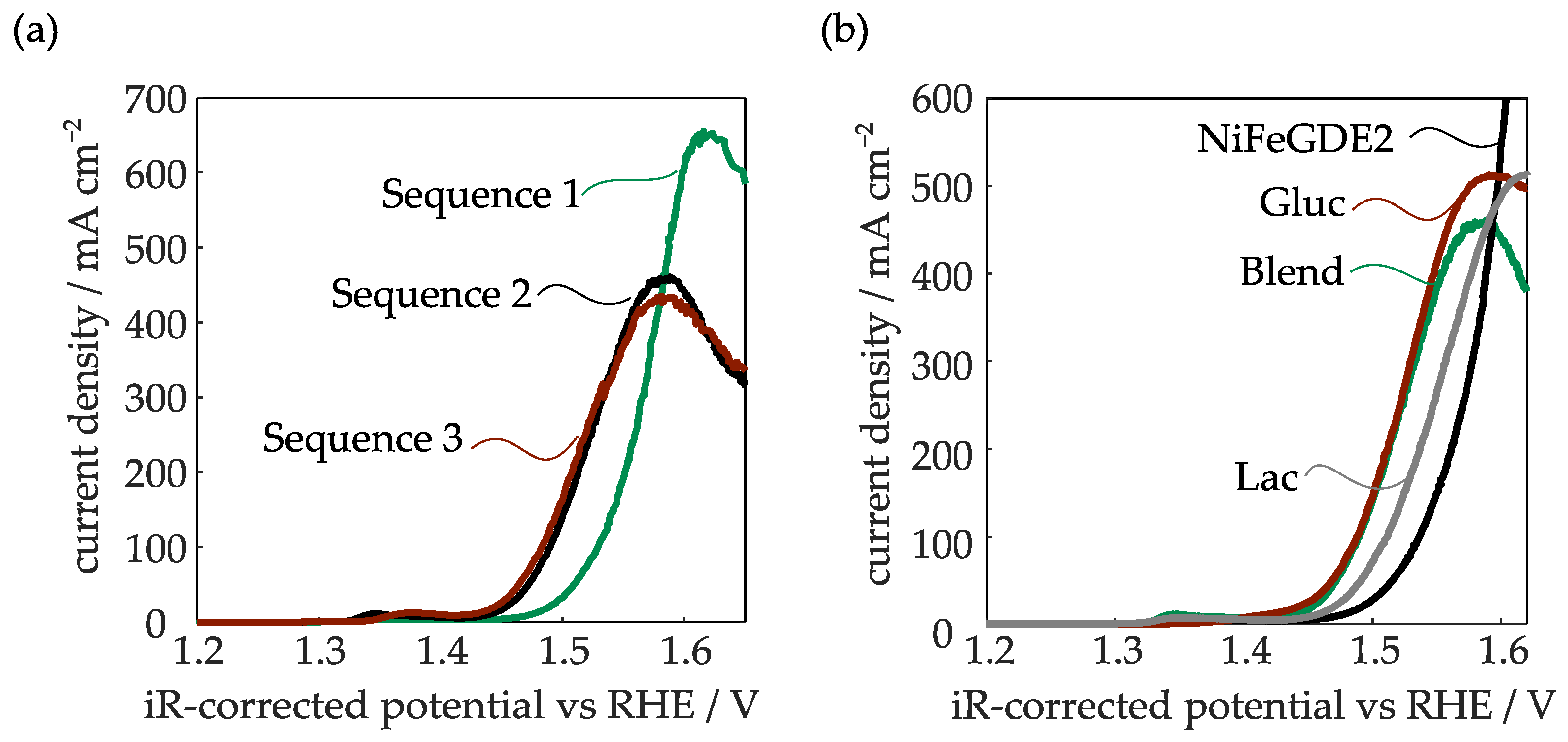
As an example, Figure 4a depicts the running-in behavior of the Blend GDE. It can be seen that during the first sequence, a higher potential is applied and the mass transport limitation occurs at a higher current density than in the subsequent measurement sequences, where a lower onset potential, but also an earlier mass transfer limitation, occurred. It is evident that the results of the second and third measurement sequences closely overlap; thus, consistent and comparable results can be obtained. A comparison of the LSVs after the run-in procedure reveals significant differences between the GDEs, Figure 4b. For further analysis, the LSV results are separated into three distinct regimes. Firstly, the kinetic regime up to approx. 100 mA cm−2, which is mainly influenced by the electrochemically active surface area, as well as Tafel slope and exchange current density. Obviously, the Gluc and Blend GDEs reveal favorable performance in this regime compared to the Lac GDE, as well as the NiFeGDE2 from our earlier work. The kinetic parameters of the different electrodes are further discussed in Section 2.2.2. The second regime at current densities above 100 mA cm−2 is mainly influenced by ohmic losses. It can be seen that relatively similar slopes are observed in this quasi-linear regime, with little differences between the electrodes.
Finally, the potential curves reach their individual limiting current densities, which become visible as the peaks in Figure 4. Shortly before this point, regime three begins, in which mass transport limitations become dominant. The mass transport limitation is also the reason for the unusual peak shape of the measurements [37]. Due to the continuously increasing potentials, the gas production rate increases with the thickness of the diffusion layer until the barrier reaches a maximum thickness, which limits the maximum mass transfer of the reactant to the electrode. Therefore, the diffusion rate is lower than the consumption of the reactant, and thus, the current does not increase any further. At higher potentials, the current density approaches a steady-state value. The observed limiting current densities (polarization curve peaks) differ significantly between the electrodes. Interestingly, only the NiFeGDE2 does not reach the mass transport limitation at the maximum current density of 1000 mA cm−2. For the newly developed GDEs, the mean pore diameter is higher for the Gluc and Lac GDE compared to the Blend GDE (see Table 1), which enhances transport processes, and might explain why the limitation occurs at higher current density. Additionally, produced oxygen gas could be removed more easily due to small cracks, as present in the Gluc GDE. Kong et al. [38] performed a systematic study of the influence of cracks in a GDE during electrochemical CO2 reduction. They found that superficial cracks can increase performance by functioning as flow fields that cause better electrolyte delivery and gas removal. Due to this improved liquid transport, the micropores do not become flooded, providing a larger active reaction area. This effect might be responsible for the performance of the Gluc GDE. However, it is not clear why the NiFeGDE2 had a better performance regarding the limiting current density, despite only minor differences in the pore system of the electrodes (see Table 1). On the other hand, Figure 4b also shows that the newly developed GDEs outperform the earlier measurement results of Koj et al. [8] up to a current density of 400 mA cm−2, which is a typical value for the classical AEL with concentrated liquid electrolyte [4]. Nevertheless, further investigations are required to understand the relationship between GDE structure and limiting current density, and to develop improved GDE formulations.

2.2.2. Tafel and EIS Analysis

The evaluation of the kinetic parameters of the different electrodes shows that the Tafel slopes are relatively similar in a range of approx. 60 mV dec−1 (see Table 2 and Figures S1–S3 in the Supplementary Materials), while the determined exchanged current densities also only differ by a factor of about two. Nevertheless, the measured overpotentials of the GDEs developed in this work, especially for the best electrodes (Gluc and Blend), are significantly lower (by approx. 30 mV) than those measured with the previously described NiFeGDE2 [8]. These best performing GDEs reach overpotentials in very good agreement with Marini et al. [21], who reported a value of 267 mV at 100 mA cm−2. Obviously, the developed preparation method leads to highly active electrodes, most probably containing Fe-oxyhydroxides in combination with Ni-oxyhydroxide [16,39,40,41].
During the series of measurements (for sequence details see Section 3.4), several EIS measurements were also performed at different potentials, Figures S6–S8. The Nyquist plot shows two semicircles. While the first semicircle indicates the filling of the pores with electrolyte, the second semicircle indicates the charge transfer resistance between the electrode and the electrolyte [42,43]. Alobaid et al. [42] performed similar experiments with a Ni foam, onto which a nickel-iron double hydroxide layer was deposited. In agreement with our work, these authors also observed that the resistance decreases with increasing potential. It was assumed that the decrease of the first semicircle indicates a rising OER activity, while the decrease of the second semicircle is due to reduced charge transfer limitations.

2.2.3. Temperature Influence

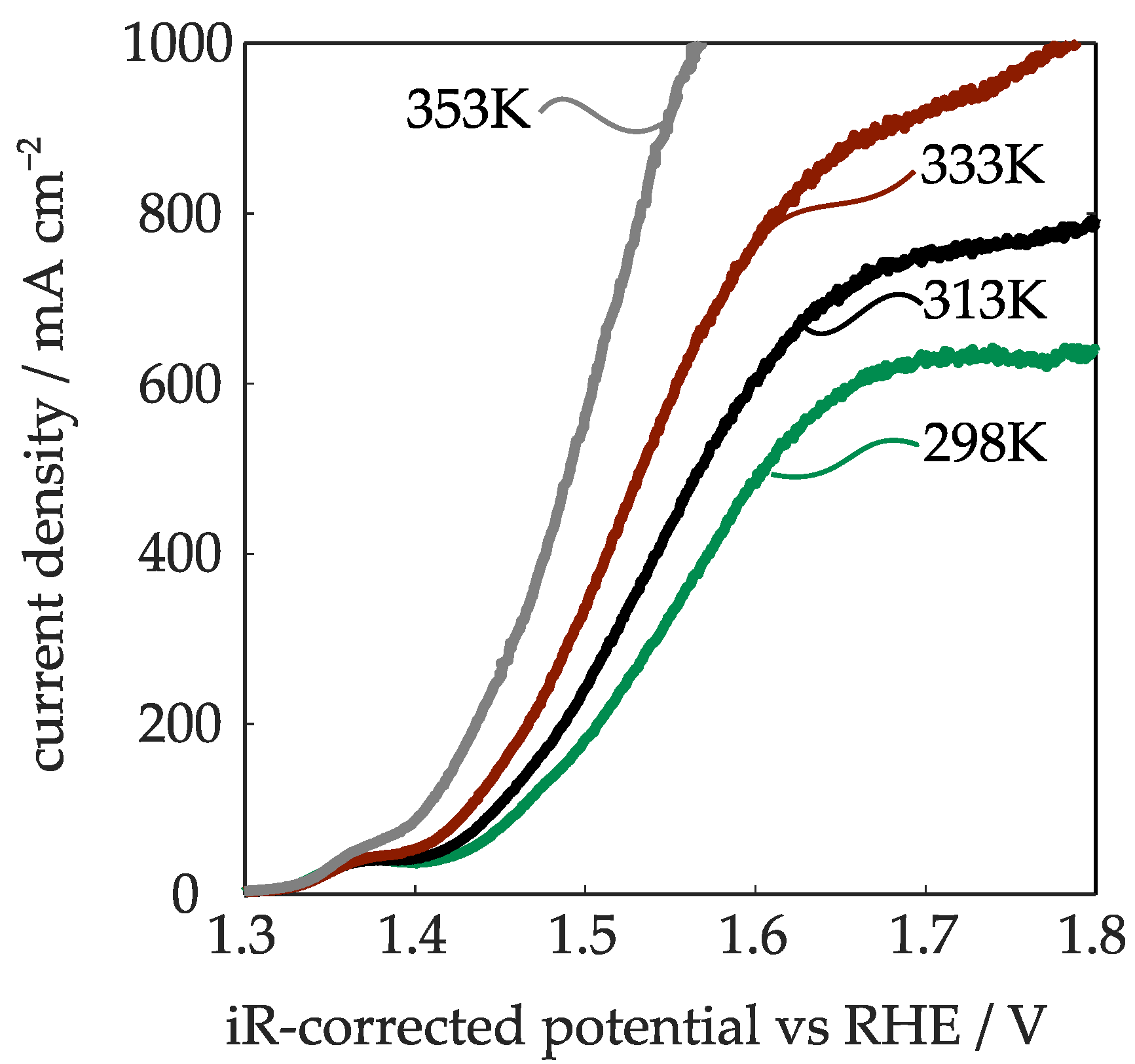
In the previous Section, it was demonstrated that the Blend and Gluc GDEs exhibit the best electrochemical performance. However, the Blend GDE can be handled much easier, since it is relatively flexible and mechanically more stable than the brittle Gluc GDE. For this reason, the performance at elevated temperature, as well as the long-term stability of the Blend GDE, were investigated at technically relevant current densities. For these experiments, a newly manufactured Blend GDE was used, which has to be kept in mind when comparing the results with Figure 4. First, the GDE was characterized by LSV measurements at different temperatures. To ensure a complete wetting of the pores, the GDE was conditioned with the same measurement protocol as described earlier (c.f. Section 2.2.1). The results of the LSV measurements at different temperatures are depicted in Figure 5. One can see that the active species are formed at all temperatures in the potential range between 1.3 and 1.4 V vs. RHE [44], where the current–voltage response remains constant regardless of the chosen temperature. Compared to Figure 4b, the Blend GDE shows an approximately 100 mA cm−2 higher limiting current density, while the performance in the kinetic region is slightly worse. These minor differences are presumably due to slight variations occurring during the manual manufacturing process.
Figure 5 reveals that not only the expected improvement in the kinetic region occurred at rising temperature, but alsoshift to higher limiting current densities. The reasons for the kinetic enhancement are the activation of the electrochemical processes, as well as an increase of the electrolyte conductivity with rising temperature [8,10]. In the previous work by Koj et al. [8], these effects were analyzed through EIS measurements, which showed a reduction of the specific resistance from 0.72 Ω cm2 at 298 K to 0.44 Ω cm2 at 353 K. In the present study, we observed specific resistances of approx. 0.78 Ω cm2 at room temperature, and about 0.44 Ω cm2 at 353 K (Figure S4). A possible explanation for the observed shift of the mass transport limitation towards higher current densities at rising temperature could be the electrolyte viscosity, which decreases from 2.74 mPa s at 298 K to 0.99 mPa s at 353 K [45]. As a consequence, electrolyte can permeate through the separator and into the GDE more easily, facilitating the transport of hydroxide ions to the active sites. The permeation through ZirfonTM Perl has been investigated in other studies, showing an increase with rising temperatures [46].
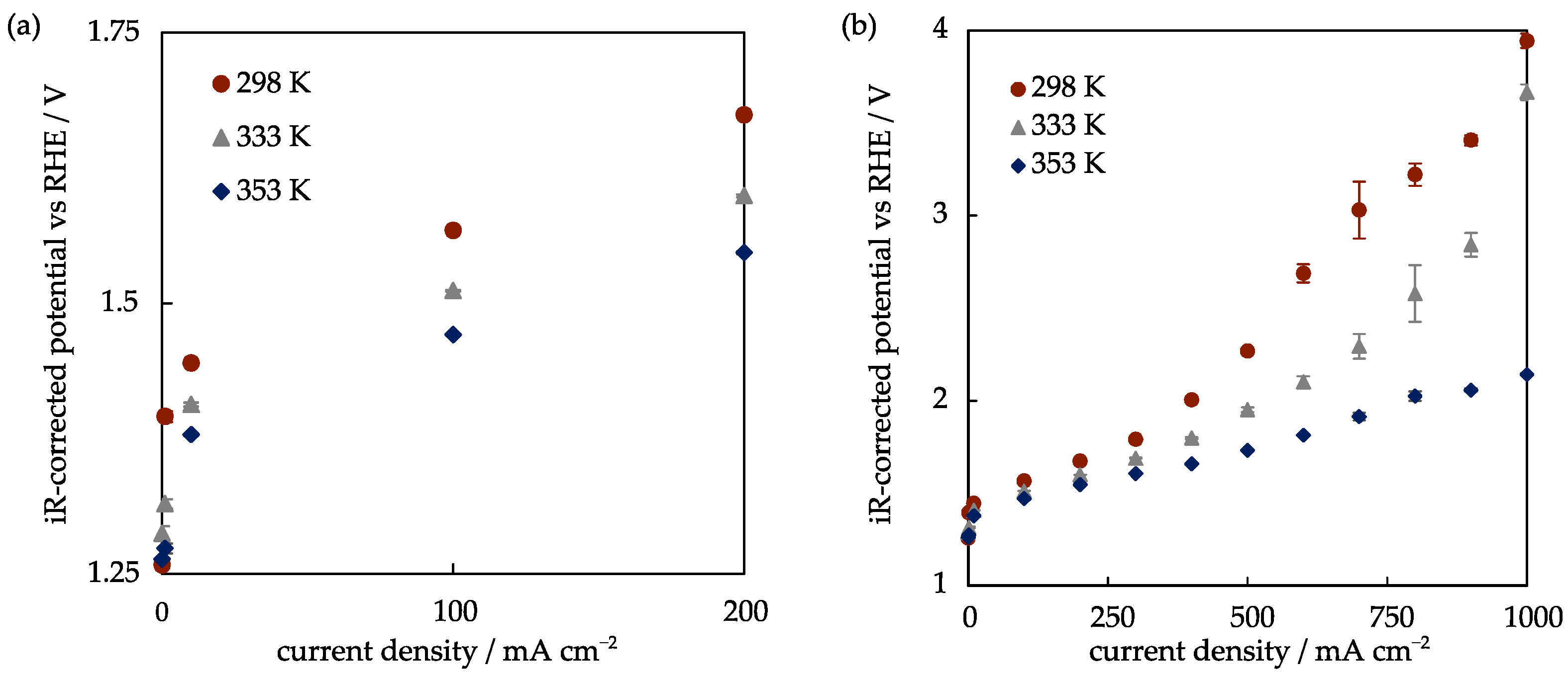
In addition to the LSV measurements, the GDEs were characterized using polarization curves obtained through CP measurements at various current densities. This allows the electrodes to be tested for their long-term stability under industrially relevant conditions. During these experiments, the current densities were kept constant for 1800 s, and the last 1300 s were evaluated when the electrode performance had been stabilized. Figure 6 depicts the polarization curves at room temperature, 333 K, and 353 K. The measured values are in good agreement with the earlier obtained LSV results, however, with certain differences due to the altered measurement protocols. Figure 6a shows a similar temperature trend in the kinetic regime, as during the LSV measurements summarized in Figure 5. On the other hand, Figure 6b shows interesting differences compared to the LSV investigations. Whereas current densities of about 600 mA cm−2 (298 K) and 800–900 mA cm−2 (333 K) could not be exceeded during the potential-driven LSV measurements, the GDE reached significantly higher current densities in the CP measurements, although at relatively high potentials. This shows that possible limiting current densities under technically relevant conditions, where a certain current density is imposed, are of lesser concern. The error bars in Figure 6b are used to visualize observed fluctuations of the measured potentials at higher current density, probably due to bubble formation inside the GDE.
The CP measurements were also used to determine the overpotentials at different temperatures (Table 3). One can see that the overpotential of the Blend GDE decreased by 34 mV at 10 mA cm−2, and by 32 mV at 100 mA cm−2 upon raising the temperature from 298 K to 353 K. Overall, these values are about 10–30 mV lower than corresponding overpotentials reported in the studies by Koj et al. and Marini et al. [8,21].
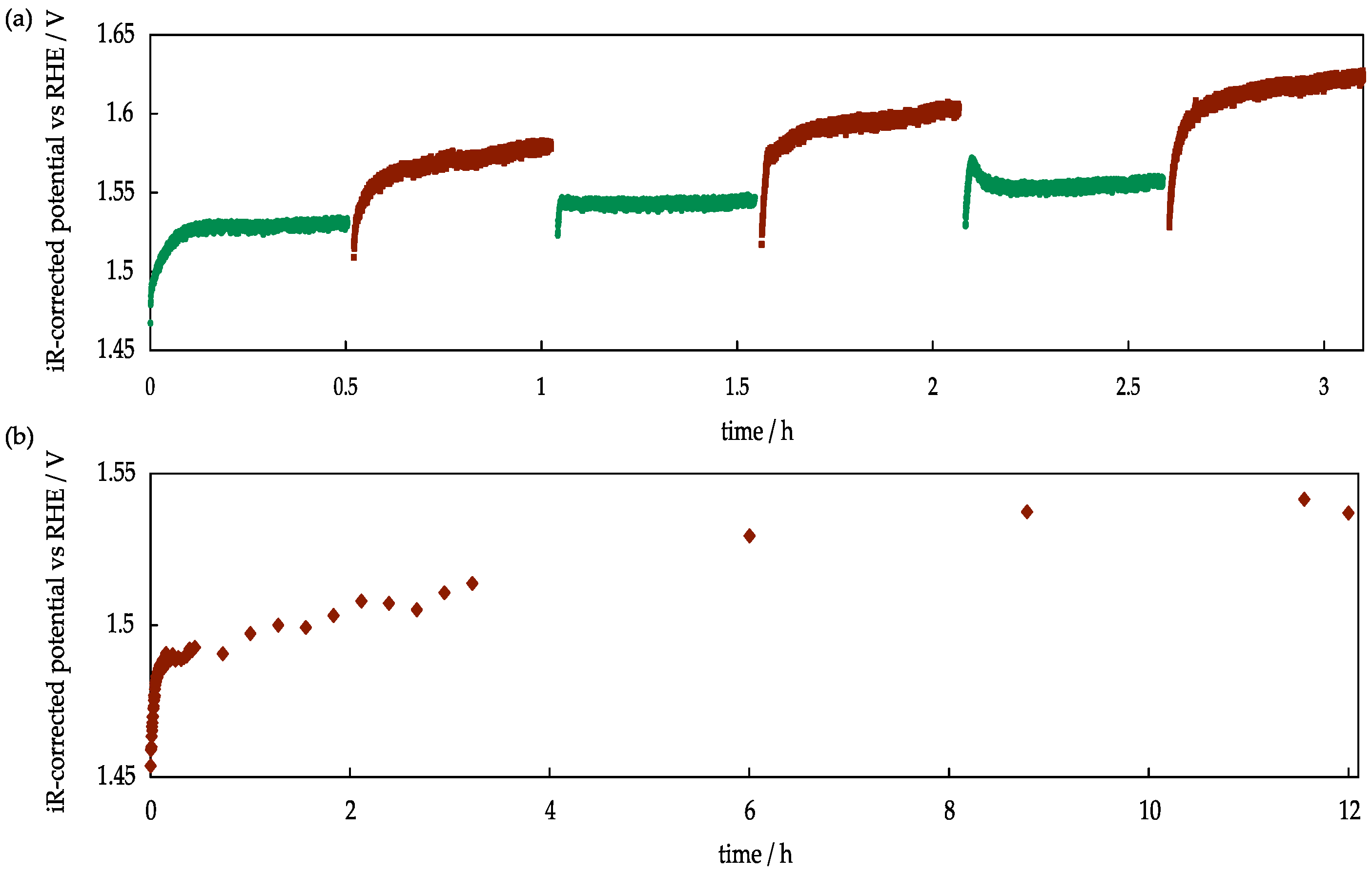
A final series of experiments was conducted to evaluate the behavior of the Blend GDE during prolonged operation. In Figure 7a, the results obtained from an alternating current density of 300 and 400 mA cm−2 are shown. It can be seen that the GDE reaches a steady state at the lower current density relatively quickly, whereas after 0.5 h at 400 mA cm−2, a stable performance was not yet reached. After switching back to 300 mA cm−2, the steady-state potential had slightly increased. These effects continue to occur upon repeated current density switches. These experiments show that operation of the GDE at higher current density requires a longer time to reach a steady state, and also that permanent changes of the electrode performance are obviously induced. In order to shed further light into this run-in behavior, an additional experiment at 400 mA cm−2 was carried out for 12 h. As shown in Figure 7b, it took approximately 8 h for the potential to stabilize. Interestingly, the final potential is slightly below 1.55 V lower than during the switching experiments depicted in Figure 7a. This shows that complex time-dependent phenomena occur in these GDEs, which must be thoroughly investigated in future research. Possible reasons for the observed dynamics are a different electrolyte distribution inside the GDE, resulting in different wetted and catalytically active areas, or the formation of a gas cushion between the GDE and separator, especially at higher current density. Furthermore, a gradual dissolution of iron present in the porous GDE structure by KOH might occur, leading to performance degradation. Another contributing factor to the potential increase is most probably the accumulation of KOH over time, leading to a decrease in conductivity. To mitigate this effect, the experiments should be repeated with stoichiometric water dosing to prevent any KOH concentration deviations.
Despite these remaining open questions, the measurements clearly show that stable performance of the newly developed GDE during prolonged operation at a technically relevant current density of 400 mA cm−2 is possible.

3. Materials and Methods

3.1. GDE Manufacture

The GDEs were manufactured following the methodology described by Koj et al. [15]. The process can be separated into four steps: dispersing, spraying, hot pressing, and sintering. A suspension was made of Ni particles (purity 99.9%, average particle size 3–7 µm, ThermoFisher GmbH, Karlsruhem Germany), a 1 wt.% hydroxyethylmethyl cellulose solution (MC, Walocel™, Dow Wolff Cellulosics GmbH, Bomlitzm Germany), a polytetrafluoroethylene (PTFE) dispersion (TF5060GZ, 3M™ Dyneon™, Dyneon GmbH, Burgkirchen an der Alz, Germany), demineralized water, and an iron precursor compound. The employed precursors were iron(II) gluconate dihydrate (purity 97%, Carl Roth GmbH + Co. KG, Karlsruhe, Germany) and iron(II) lactate hydrate (purity 98%, Sigma Aldrich Chemie GmbH, Darmstadt, Germany). In order to form a suspension, an Ultra-Turrax (T25, Basic, IKA-Werke GmbH & Co. Kg, Staufen im Breisgau, Germany) and a dispersing rod (S25N-25F, IKA-Werke GmbH & Co. Kg, Germany) were used. To ensure homogeneity of the suspension, it was mixed two times for five minutes at 13,500 rpm, with a five-minute break in between. During the dispersion process, the suspension was cooled by a water bath. For the second spraying step, an airbrush gun (Sogolee HP 320, nozzle 0.3 mm, Conrad Electronic SE, Wernberg-Köblitz, Germany) with nitrogen (gaseous N2 grade 5.0, Linde AG) as carrier gas was used. The suspension was sprayed onto a Ni mesh (80 µm × 80 µm mesh size, 126 µm thickness, Haver&Boecker OHG, Oelde, Germany) placed on a heating table (403 K). The target NiFe load was 75 mg cm−2, which was verified with an analytical balance (BCE623-1S, Sartorius, Göttingen, Germany). In the third step, the GDEs were hot pressed (LaboPress P200S, Vogt Labormaschinen GmbH, Berlin, Germany, 150 kg cm−2, 5 min, 403 K). The last sintering process step was performed at a temperature of 603 K for 15 min in an oven (N20/HR, Nabertherm GmbH, Lilienthal, Germany) under an air atmosphere. In this step, the residue of the iron components, water and hydroxyethylmethyl cellulose, evaporated and burned out, respectively, to generate the intended porous structure. In order to compare the GDEs with the NiFeGDE2 electrode from Koj et al. [15], the hydroxyethylmethyl cellulose ratio of the dry GDE before sintering was kept constant at 3 wt.%. The PTFE and Fe contents in the sintered GDE were 3 wt.% and 2 wt.%, respectively. For this purpose, the Lac GDE contained 7.4 wt.% iron(II) lactate, the Gluc GDE 14.3 wt.% iron(II) gluconate, and the Blend GDE 5 wt.% iron(II) lactate and 5 wt.% iron(II) gluconate. These values refer to the dry GDE before the sintering step.

3.2. Physical Characterization

For the calculation of the median thickness, the GDEs were measured at six different points with a dial gauge (type: 12.5 mm/0.001, Käfer Messuhrenfabrik GmbH, Villingen-Schwenningen, Germany). The flow-through pores and the bubble point pressure were measured with a porometer (3G, Quantachrome Instruments, Boynton Beach, FL, USA) with Porofil® (3P Instruments GmbH, Odelzhausen, Germany) as wetting fluid, and nitrogen (5.0, Linde AG) used as inert gas. The bubble point pressure was determined according to test method ARP901A (Society of Automotive Engineers [47]). In the flow-through pore distribution study, the wet and dry runs are compared in a range of 0.2 µm to 20 µm. The determination of the pore size distribution was carried out with mercury porosimetry (Pascal 140 and 440, Thermo Fisher Scientific). These measurements were used to calculate the pore diameter using the Solid software suite (Thermo Fisher Scientific, Monza, Italy). An additional parameter for the calculation of the pore diameter was the density, which was measured with a helium pycnometer (Pycnomatic ATC, Nuova A.E.Z. Srl, Camburzano, Italy). The specific surface area was determined in a 3Flex surface characterization analyzer (Micromeritics Instruments, GA, USA). The Brunauer–Emmett–Teller (BET) method with krypton as adsorbate was chosen for the analysis. A microscope (Keyence VHX) was used for analyzing the surface of the GDEs.

3.3. Electrochemical Cell

The GDEs were characterized as working electrodes in a custom-made half cell consisting of polymethyl methacrylate frames (Perspex®, W. Max Wirth GmbH, Braunschweig, Germany) in a three-electrode configuration. The counter electrode consisted of a Ni mesh (500 µm × 500 µm mesh size, 250 µm thickness, Haver&Boecker OHG, Oelde, Germany). A Hg/HgO electrode (RE-61AP, ALS Co., Ltd., Kanagawa, Japan) was used as reference electrode. The single compartments were separated by two Zirfon™ Perl UTP 500 separators (Agfa-Gevaert, Mortsel, Belgium). A contact pressure of 2.5 kg cm−2 was chosen to ensure a good electrical contact and to prevent the formation of a gas cushion between the separator and the GDE. The geometrical surface area of the GDEs and the separator was 3.14 cm2. All compartments were sealed with silicon gaskets (LEZ-SIL 60-TF, 0.8 mm thickness, AET Lezaud GmbH, St. Wendel, Germany). The cell components were held by screws fastened at 2.5 Nm. The electrolyte volume flow rate was set to 10 mL min−1.

3.4. Electrochemical Techniques

For the electrochemical measurements, the half cell was filled up with 32 wt.% KOH electrolyte (99.9%, Honeywell, Praha, Czech Republic), followed by a rest time of 0.5 h to allow the electrolyte to wet the separator. During the rest time and the experiments, the electrolyte compartments were flushed with nitrogen (grade: 5.0) at a flow rate of 0.5 L min−1 to ensure a nonexplosive gas mixture, and to prevent CO2 contamination of the electrolyte [15]. Operating conditions were ~298 K and ambient pressure. Measurements were carried out with a Gamry Reference 3000 potentiostat. The measurement started with the assignment of the open circuit potential (OCP) when a stability of 0.1 mV s−1 was reached. This was followed by a cyclic voltammetry with scan limits to 50 mV above and below the OCP value, and scan rates of 0.05 to 0.8 V s−1 with 5 cycles for each scan rate. Afterwards, electrochemical impedance spectroscopy (EIS) was performed at OCP to measure the ohmic resistance, using an AC amplitude of 5 mV and a frequency range between 150 kHz and 0.1 Hz. Conditioning the GDE was performed in the next step for 150 s at 10 mA cm−2, followed by linear sweep voltammetry (LSV). The LSV scan was performed from 1.0 V to 1.8 V vs. RHE at a scan rate of 1 mV s−1 two times in series. Afterwards, a multiple-step chronopotentiometry (mCP) measurement was performed for 60 s at different current densities. In order to complete the measuring sequence, an LSV in the potential range of 1 to 1.8 V vs. RHE at a scan rate of 5 mV s−1 was carried out. The exchange current density and the Tafel slope were determined from the third LSV. For the calculation of the overpotential η (Equation (1)), the equilibrium potential ( U r e v 0 ) as a function of temperature, activity coefficients, and vapor pressure were taken into account, according to Koj et al. [48].
  η = U R H E U r e v 0
The overvoltage was corrected by the ohmic resistance of the cell assembly, which was identified at the intersection of the z-real axis in the Nyquist plot (see Figures S5–S8) [49]. For the analysis of the overpotential, the mCP measurements were used. The analysis of the current exchange density and the Tafel slope was determined in the low overpotential region (220 mV to 350 mV) for current densities between 1 and 100 mA cm−2, where the curve shows a linear relationship between log(j) and the overpotential (Figures S1–S3). Therefore, the determination of the Tafel slope b (Equation (2)) was calculated after the formation of the active species, indicated by the peaks in Figures S1–S3. The intersection with the y-axis of the regressed function [50,51] then yields the exchange current densities (j0), which are summarized in Table 2. All electrochemical measurements were performed at least three times with three different GDEs produced from the same suspension. The measurement results were recalculated versus the reversible hydrogen electrode (RHE) with Equation (3).
log j = η · b + log j 0
U R H E = U H g / H g O + 0.931   V
Prior to the CP measurement, OCP and EIS measurements were performed. The measurement at a constant current density was conducted for 1800 s before moving on to the next current density. Following the CP measurement, another EIS measurement was conducted. For the temperature measurements, the KOH electrolyte was heated up in a 250 mL wide mouth flask located in a heating bath.

4. Conclusions

This work presents the development of improved GDEs for the OER in alkaline water electrolysis in a novel hybrid AEL process with only one electrolyte cycle at the cathode. It could be shown that it is possible to replace the very expensive iron(II) acetate precursor by more cost-effective components, such as iron(II) lactate and iron(II) gluconate, in the manufacturing process. Since the mechanical properties of the GDEs obtained from these precursors, Gluc and Lac, were very different, a combination of the two iron precursor compounds was also investigated, and denoted as Blend GDE. The newly developed GDEs had a pore structure comparable to those reported by Koj et al. [15]. The electrochemical testing of the GDEs revealed that the Gluc and Blend GDE allowed operation at the highest current density, and that these electrodes are more active in the kinetic regime than earlier developed formulations. Due to the favorable mechanical properties, the Blend GDE was selected for further investigation at higher temperatures. These measurements showed that not only was the performance in the kinetic regime enhanced by raising the temperature, but also higher limiting current densities could be reached. Long-term experiments at an industrially viable current density of 400 mA cm−2 showed a run-in behavior with rising potentials, but after about 8 h, a stable electrode performance was achieved. Overall, these findings, based on more cost-effective iron precursors for GDE manufacture, are a good starting point for further optimization of this novel AEL concept.

Supplementary Materials

The following supporting information can be downloaded at: https://www.mdpi.com/article/10.3390/catal13091266/s1, Figure S1: Tafel slope and exchange current density of the Blend GDE, Figure S2: Tafel slope and exchange current density of the Gluc GDE, Figure S3: Tafel slope and exchange current density of the Lac GDE, Figure S4: Nyquist plots of the Blend GDE at different temperatures before the LSV measurements, Figure S5: Nyquist plots of the Blend, Lac, and Gluc GDE at a current density of 10 mA cm−2, Figure S6: Nyquist plots of the Blend GDE at different potentials. Grey triangles depict measurements at a potential of 1.4 V vs. RHE, red squares refer to 1.475 V vs. RHE, and green circles to 1.5 V vs. RHE, Figure S7: Nyquist plots of the Gluc GDE at different potentials. Grey triangles refer to a potential of 1.4 V vs. RHE, red squares to 1.475 V vs. RHE, and green circles to 1.5 V vs. RHE, Figure S8. Nyquist plots of the Lac GDE at different potentials. Grey triangles refer to a potential of 1.4 V vs. RHE, red squares to 1.475 V vs. RHE, and green circles to 1.5 V vs. RHE.

Author Contributions

Conceptualization F.G., J.B. and M.K.; methodology, M.K., F.G. and J.B.; validation, M.K. and F.G.; investigation, M.K. and F.G.; writing— original draft preparation, M.K. and F.G.; writing—review and editing, J.B. and T.T.; visualization, M.K.; supervision, T.T.; project administration, T.T.; funding acquisition, T.T.; All authors have read and agreed to the published version of the manuscript.

Funding

This research was funded by Deutsche Forschungsgemeinschaft (DFG, German Research Foundation), project number 450621348.

Data Availability Statement

Reported data will be available on request.

Acknowledgments

We acknowledge support by Open Access Publishing Fund of Clausthal University of Technology. The authors are thankful to Luis Fernando Arenas for fruitful discussions.

Conflicts of Interest

The authors declare no conflict of interest.

References

  1. IEA—International Energy Agency. Global Hydrogen REVIEW 2021. Available online: https://iea.blob.core.windows.net/assets/5bd46d7b-906a-4429-abda-e9c507a62341/GlobalHydrogenReview2021.pdf (accessed on 16 August 2023).
  2. McKinsey & Company. Hydrogen for Net-Zero: A Critical Cost-Competitive Energy Vector. Available online: https://hydrogencouncil.com/wp-content/uploads/2021/11/Hydrogen-for-Net-Zero.pdf (accessed on 25 August 2023).
  3. McKinsey & Company. Hydrogen Insights: A Perspective on Hydrogen Investment Market Development and Cost Competitiveness. Available online: https://hydrogencouncil.com/wp-content/uploads/2021/02/Hydrogen-Insights-2021.pdf (accessed on 24 August 2023).
  4. Moberg, J.; Bartlett, B. The Mirage of Blue Hydrogen is Fading. Available online: https://gh2.org/blog/mirage-blue-hydrogen-fading (accessed on 18 August 2023).
  5. Zhang, H.; Guan, D.; Hu, Z.; Huang, Y.-C.; Wu, X.; Dai, J.; Dong, C.-L.; Xu, X.; Lin, H.-J.; Chen, C.-T.; et al. Exceptional lattice-oxygen participation on artificially controllable electrochemistry-induced crystalline-amorphous phase to boost oxygen-evolving performance. Appl. Catal. B Environ. 2021, 297, 120484. [Google Scholar] [CrossRef]
  6. Guan, D.; Xu, H.; Zhang, Q.; Huang, Y.-C.; Shi, C.; Chang, Y.-C.; Xu, X.; Tang, J.; Gu, Y.; Pao, C.-W.; et al. Identifying A Universal Activity Descriptor and a Unifying Mechanism Concept on Perovskite Oxides for Green Hydrogen Production. Adv. Mater. 2023, e2305074. [Google Scholar] [CrossRef] [PubMed]
  7. Etzold, B.J.; Krewer, U.; Thiele, S.; Dreizler, A.; Klemm, E.; Turek, T. Understanding the activity transport nexus in water and CO2 electrolysis: State of the art, challenges and perspectives. Chem. Eng. J. 2021, 424, 130501. [Google Scholar] [CrossRef]
  8. David, M.; Ocampo-Martínez, C.; Sánchez-Peña, R. Advances in alkaline water electrolyzers: A review. J. Energy Storage 2019, 23, 392–403. [Google Scholar] [CrossRef]
  9. Chatenet, M.; Pollet, B.G.; Dekel, D.R.; Dionigi, F.; Deseure, J.; Millet, P.; Braatz, R.D.; Bazant, M.Z.; Eikerling, M.; Staffell, I.; et al. Water electrolysis: From textbook knowledge to the latest scientific strategies and industrial developments. Chem. Soc. Rev. 2022, 51, 4583–4762. [Google Scholar] [CrossRef] [PubMed]
  10. Schmidt, O.; Gambhir, A.; Staffell, I.; Hawkes, A.; Nelson, J.; Few, S. Future cost and performance of water electrolysis: An expert elicitation study. Int. J. Hydrogen Energy 2017, 42, 30470–30492. [Google Scholar] [CrossRef]
  11. Buttler, A.; Spliethoff, H. Current status of water electrolysis for energy storage, grid balancing and sector coupling via power-to-gas and power-to-liquids: A review. Renew. Sustain. Energy Rev. 2018, 82, 2440–2454. [Google Scholar] [CrossRef]
  12. Brauns, J.; Turek, T. Alkaline Water Electrolysis Powered by Renewable Energy: A Review. Processes 2020, 8, 248. [Google Scholar] [CrossRef]
  13. Haug, P.; Koj, M.; Turek, T. Influence of process conditions on gas purity in alkaline water electrolysis. Int. J. Hydrogen Energy 2017, 42, 9406–9418. [Google Scholar] [CrossRef]
  14. Perry, S.C.; Ponce de León, C.; Walsh, F.C. Review—The Design, Performance and Continuing Development of Electrochemical Reactors for Clean Electrosynthesis. J. Electrochem. Soc. 2020, 167, 155525. [Google Scholar] [CrossRef]
  15. Koj, M.; Qian, J.; Turek, T. Novel alkaline water electrolysis with nickel-iron gas diffusion electrode for oxygen evolution. Int. J. Hydrogen Energy 2019, 44, 29862–29875. [Google Scholar] [CrossRef]
  16. Koj, M.; Gimpel, T.; Schade, W.; Turek, T. Laser structured nickel-iron electrodes for oxygen evolution in alkaline water electrolysis. Int. J. Hydrogen Energy 2019, 44, 12671–12684. [Google Scholar] [CrossRef]
  17. Gilliam, R.; Graydon, J.; Kirk, D.; Thorpe, S. A review of specific conductivities of potassium hydroxide solutions for various concentrations and temperatures. Int. J. Hydrogen Energy 2007, 32, 359–364. [Google Scholar] [CrossRef]
  18. Becker, H.; Murawski, J.; Shinde, D.V.; Stephens, I.E.L.; Hinds, G.; Smith, G. Impact of impurities on water electrolysis: A review. Sustain. Energy Fuels 2023, 7, 1565–1603. [Google Scholar] [CrossRef]
  19. Haug, P.; Kreitz, B.; Koj, M.; Turek, T. Process modelling of an alkaline water electrolyzer. Int. J. Hydrogen Energy 2017, 42, 15689–15707. [Google Scholar] [CrossRef]
  20. Trinke, P.; Haug, P.; Brauns, J.; Bensmann, B.; Hanke-Rauschenbach, R.; Turek, T. Hydrogen Crossover in PEM and Alkaline Water Electrolysis: Mechanisms, Direct Comparison and Mitigation Strategies. J. Electrochem. Soc. 2018, 165, F502–F513. [Google Scholar] [CrossRef]
  21. Song, F.; Bai, L.; Moysiadou, A.; Lee, S.; Hu, C.; Liardet, L.; Hu, X. Transition Metal Oxides as Electrocatalysts for the Oxygen Evolution Reaction in Alkaline Solutions: An Application-Inspired Renaissance. J. Am. Chem. Soc. 2018, 140, 7748–7759. [Google Scholar] [CrossRef]
  22. Schmidt, V.M. Elektrochemische Verfahrenstechnik: Grundlagen, Reaktionstechnik, Prozeßoptimierung; Wiley-VCH: Weinheim, Germany, 2004; ISBN 3527602143. [Google Scholar]
  23. Louie, M.W.; Bell, A.T. An investigation of thin-film Ni-Fe oxide catalysts for the electrochemical evolution of oxygen. J. Am. Chem. Soc. 2013, 135, 12329–12337. [Google Scholar] [CrossRef]
  24. Guo, B.; Ding, Y.; Huo, H.; Wen, X.; Ren, X.; Xu, P.; Li, S. Recent Advances of Transition Metal Basic Salts for Electrocatalytic Oxygen Evolution Reaction and Overall Water Electrolysis. Nano-Micro Lett. 2023, 15, 57. [Google Scholar] [CrossRef]
  25. Franzen, D.; Ellendorff, B.; Paulisch, M.C.; Hilger, A.; Osenberg, M.; Manke, I.; Turek, T. Influence of binder content in silver-based gas diffusion electrodes on pore system and electrochemical performance. J. Appl. Electrochem. 2019, 49, 705–713. [Google Scholar] [CrossRef]
  26. Bienen, F.; Paulisch, M.C.; Mager, T.; Osiewacz, J.; Nazari, M.; Osenberg, M.; Ellendorff, B.; Turek, T.; Nieken, U.; Manke, I.; et al. Investigating the electrowetting of silver-based gas-diffusion electrodes during oxygen reduction reaction with electrochemical and optical methods. Electrochem. Sci. Adv. 2023, 3, 494. [Google Scholar] [CrossRef]
  27. Zhang, G.-R.; Shen, L.-L.; Schmatz, P.; Krois, K.; Etzold, B.J. Cathodic activated stainless steel mesh as a highly active electrocatalyst for the oxygen evolution reaction with self-healing possibility. J. Energy Chem. 2020, 49, 153–160. [Google Scholar] [CrossRef]
  28. Chen, H.; Li, J.; Shen, Y.; Jiao, W.; Wang, J.; Zou, Y.; Zou, X. Room temperature, fast fabrication of square meter-sized oxygen evolution electrode toward industrial alkaline electrolyzer. Appl. Catal. B Environ. 2022, 316, 121605. [Google Scholar] [CrossRef]
  29. Sequeira, C.A.C.; Santos, D.M.F.; Šljukić, B.; Amaral, L. Physics of Electrolytic Gas Evolution. Braz. J. Phys. 2013, 43, 199–208. [Google Scholar] [CrossRef]
  30. Marini, S.; Salvi, P.; Nelli, P.; Pesenti, R.; Villa, M.; Kiros, Y. Oxygen evolution in alkali with gas diffusion electrodes. Int. J. Hydrogen Energy 2013, 38, 11496–11506. [Google Scholar] [CrossRef]
  31. Graedel, T.E.; Harper, E.M.; Nassar, N.T.; Nuss, P.; Reck, B.K. Criticality of metals and metalloids. Proc. Natl. Acad. Sci. USA 2015, 112, 4257–4262. [Google Scholar] [CrossRef]
  32. Seh, Z.W.; Kibsgaard, J.; Dickens, C.F.; Chorkendorff, I.; Nørskov, J.K.; Jaramillo, T.F. Combining theory and experiment in electrocatalysis: Insights into materials design. Science 2017, 355, aad4998. [Google Scholar] [CrossRef]
  33. Sigma-Aldrich Chemie GmbH. Eisen(II)-Acetat 95% | Sigma-Aldrich. Available online: https://www.sigmaaldrich.com/DE/de/product/aldrich/339199 (accessed on 25 August 2023).
  34. Sigma-Aldrich Chemie GmbH. Eisen(II)-Lactat Hydrat ≥98.0% (Dried Material) | Sigma-Aldrich. Available online: https://www.sigmaaldrich.com/DE/de/product/aldrich/44953 (accessed on 25 August 2023).
  35. Sigma-Aldrich Chemie GmbH. Eisen(II)-D-gluconat Dihydrat 98% | Sigma-Aldrich. Available online: https://www.sigmaaldrich.com/DE/de/product/aldrich/344427 (accessed on 25 August 2023).
  36. Arenas, L.F.; Hadjigeorgiou, G.; Jones, S.; van Dijk, N.; Hodgson, D.; Cruden, A.; Ponce de León, C. Effect of airbrush type on sprayed platinum and platinum-cobalt catalyst inks: Benchmarking as PEMFC and performance in an electrochemical hydrogen pump. Int. J. Hydrogen Energy 2020, 45, 27392–27403. [Google Scholar] [CrossRef]
  37. Kreysa, G.; Ota, K.-I.; Savinell, R.F. (Eds.) Encyclopedia of Applied Electrochemistry: Chapter 3 Three-Dimensional Electrodes; The Electrosynthesis Company Inc.: New York, NY, USA, 1992; ISBN 978-1-4419-6995-8. [Google Scholar]
  38. Kong, Y.; Liu, M.; Hu, H.; Hou, Y.; Vesztergom, S.; Gálvez-Vázquez, M.d.J.; Zelocualtecatl Montiel, I.; Kolivoška, V.; Broekmann, P. Cracks as Efficient Tools to Mitigate Flooding in Gas Diffusion Electrodes Used for the Electrochemical Reduction of Carbon Dioxide. Small Methods 2022, 6, e2200369. [Google Scholar] [CrossRef]
  39. Fabbri, E.; Habereder, A.; Waltar, K.; Kötz, R.; Schmidt, T.J. Developments and perspectives of oxide-based catalysts for the oxygen evolution reaction. Catal. Sci. Technol. 2014, 4, 3800–3821. [Google Scholar] [CrossRef]
  40. Trotochaud, L.; Young, S.L.; Ranney, J.K.; Boettcher, S.W. Nickel-iron oxyhydroxide oxygen-evolution electrocatalysts: The role of intentional and incidental iron incorporation. J. Am. Chem. Soc. 2014, 136, 6744–6753. [Google Scholar] [CrossRef] [PubMed]
  41. Zou, S.; Burke, M.S.; Kast, M.G.; Fan, J.; Danilovic, N.; Boettcher, S.W. Fe (Oxy)hydroxide Oxygen Evolution Reaction Electrocatalysis: Intrinsic Activity and the Roles of Electrical Conductivity, Substrate, and Dissolution. Chem. Mater. 2015, 27, 8011–8020. [Google Scholar] [CrossRef]
  42. Alobaid, A.; Wang, C.; Adomaitis, R.A. Mechanism and Kinetics of HER and OER on NiFe LDH Films in an Alkaline Electrolyte. J. Electrochem. Soc. 2018, 165, J3395–J3404. [Google Scholar] [CrossRef]
  43. Li, G.; Anderson, L.; Chen, Y.; Pan, M.; Abel Chuang, P.-Y. New insights into evaluating catalyst activity and stability for oxygen evolution reactions in alkaline media. Sustain. Energy Fuels 2018, 2, 237–251. [Google Scholar] [CrossRef]
  44. Márquez, R.A.; Kawashima, K.; Son, Y.J.; Castelino, G.; Miller, N.; Smith, L.A.; Chukwuneke, C.E.; Mullins, C.B. Getting the Basics Right: Preparing Alkaline Electrolytes for Electrochemical Applications. ACS Energy Lett. 2023, 8, 1141–1146. [Google Scholar] [CrossRef]
  45. Hodges, A.; Renz, S.; Lohmann-Richters, F.; Al-Musawi, A.; Jupke, A.; Lehnert, W.; Swiegers, G.F.; Wallace, G.G. Critical Analysis of Published Physical Property Data for Aqueous Potassium Hydroxide. Collation into Detailed Models for Alkaline Electrolysis. J. Chem. Eng. Data 2023, 68, 1485–1506. [Google Scholar] [CrossRef]
  46. Schalenbach, M.; Lueke, W.; Stolten, D. Hydrogen Diffusivity and Electrolyte Permeability of the Zirfon PERL Separator for Alkaline Water Electrolysis. J. Electrochem. Soc. 2016, 163, F1480–F1488. [Google Scholar] [CrossRef]
  47. Bubble-Point Test Method, 2001. Available online: https://www.sae.org/standards/content/arp901a/ (accessed on 30 August 2023).
  48. Koj, M. Entwicklung und Charakterisierung von Elektroden für die Sauerstoffentwicklung in der alkalischen Wasserelektrolyse. Ph.D. Thesis, TU Clausthal, Clausthal-Zellerfeld, Germany, 2021. [Google Scholar]
  49. Ende, D.; Mangold, K.-M. Impedanzspektroskopie. Chem. Unserer Zeit 1993, 27, 134–140. [Google Scholar] [CrossRef]
  50. Shinagawa, T.; Garcia-Esparza, A.T.; Takanabe, K. Insight on Tafel slopes from a microkinetic analysis of aqueous electrocatalysis for energy conversion. Sci. Rep. 2015, 5, 13801. [Google Scholar] [CrossRef]
  51. Kubisztal, J.; Budniok, A. Study of the oxygen evolution reaction on nickel-based composite coatings in alkaline media. Int. J. Hydrogen Energy 2008, 33, 4488–4494. [Google Scholar] [CrossRef]
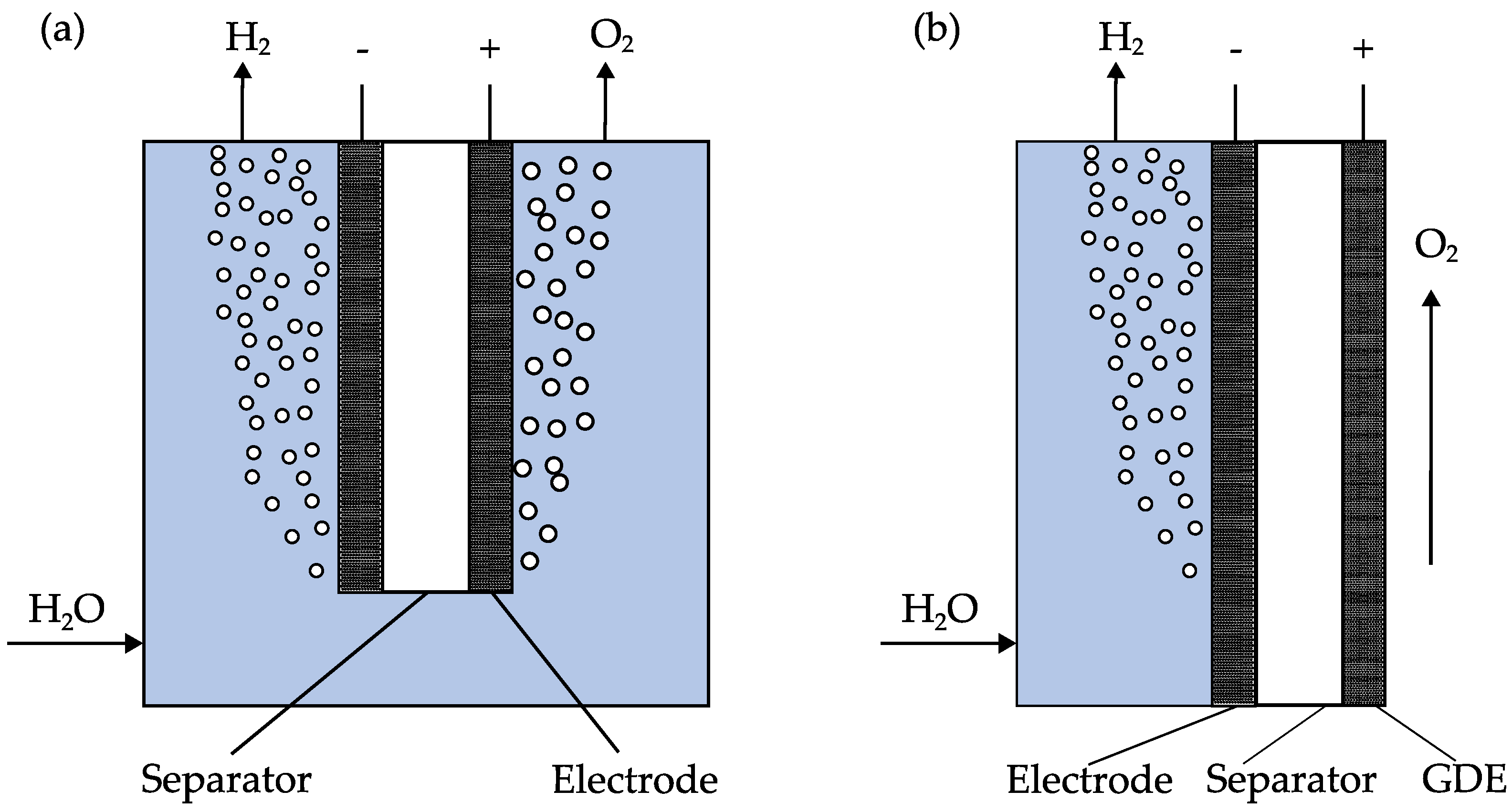
Figure 1. (a) State-of-the-art electrolysis cell, hydrogen evolves at the cathode and oxygen at the anode. To avoid concentration differences, the electrolyte is mixed by combining the anolyte and catholyte streams. (b) Hybrid electrolysis cell, hydrogen evolves at the cathode and oxygen at the anode, water that may condensate on the anodic side flows back to the cathodic side. Ideally, no electrolyte permeates through the GDE due to its hydrophobic–hydrophilic pore system.
Catalysts 13 01266 g001
Figure 2. Microscopic picture of the GDEs before ((a) Gluc, (b) Lac, (c) Blend) and after ((d) Gluc, (e) Lac, (f) Blend) the electrochemical characterization. 100× magnification.
Catalysts 13 01266 g002
Figure 3. (a) Differential flow as a function of pore diameter for the three electrodes before (solid lines) and after (dashed lines) electrochemical characterization. (b) Pore size distribution measured by mercury porosimetry.
Catalysts 13 01266 g003
Figure 4. LSV measurements with a scan rate of 1 mV s−1, measured at 25 °C, and a 32 wt.% KOH electrolyte. (a) Running-in behavior of the Blend GDE. (b) Comparison of the GDEs produced in this work with the GDE from Koj et al. [15].
Catalysts 13 01266 g004
Figure 5. LSV measurements with a scan rate of 1 mV s−1, measured at 298, 313, 333, and 353 K. The aqueous electrolyte contained 32 wt.% KOH.
Catalysts 13 01266 g005
Figure 6. Polarization curve of the Blend GDE at different temperatures in a 32 wt.% KOH electrolyte (a) in the range from 0 to 200 mA cm−2, and (b) in the range from 0 to 1000 mA cm−2.
Catalysts 13 01266 g006
Figure 7. (a) Experiments with an alternating current density of 300 mA cm−2 (green) and 400 mA cm−2 (red). (b) Long-term stability test for 12 h at 400 mA cm−2; all experiments at 353 K in 32 wt.% KOH electrolyte.
Catalysts 13 01266 g007
Table 1. Physical characteristics of the GDEs produced in this work and comparison with the NiFeGDE2 electrode from [15].
SBET/m2 g−1Mercury Porosimetry Pore CharacteristicsPorometer Flow-through Pore Characteristics
Total Pore volume/mm3 g−1Mean Pore Diameter/µmMean Flow-through Pore
Diameter/µm
Bubble Point/Bar
Lac0.52153.3 ± 6.21.41.830.22
Gluc0.78131.1 ± 4.51.912.010.24
Blend0.48159.8 ± 1.20.322.40.18
NiFeGDE2 [15]2.08120.63.781.160.22
Table 2. Tafel slope, exchange current density, and overpotentials extracted from the LSV measurements.
Tafel Slope/mV dec−1Exchange Current Density/
A cm−2
Overpotential (10/100
mA cm−2)/mV
Lac569.2∙10−7218/277
Gluc641.9∙10−6191/261
Blend516.8∙10−7204/260
NiFeGDE2 [8]577.8∙10−7233/294
Table 3. Overpotentials of the Blend GDE at different temperatures and comparison to the literature data.
ElectrodeTemperature/KOverpotential (10 mA cm−2)/mVOverpotential (100 mA cm−2)/mV
Blend298196244
Blend333184241
Blend353162212
NiFeGDE2 [15]298233294
NiFeGDE2 [15]353175224
Marini et al. [30]298-267
Disclaimer/Publisher’s Note: The statements, opinions and data contained in all publications are solely those of the individual author(s) and contributor(s) and not of MDPI and/or the editor(s). MDPI and/or the editor(s) disclaim responsibility for any injury to people or property resulting from any ideas, methods, instructions or products referred to in the content.