Article

Modular Photocatalytic Reactor for the Removal of Estrogens from Aqueous Solutions

by
Liliana Bobirică
1,
Cristina Orbeci
1,
Cristian Pîrvu
2,
Alexandra Constantinescu
2,
Elena Iuliana Bîru
3,
Giovanina Iuliana Ionică
1,
Ecaterina Matei
4,
Andrei Constantin Berbecaru
4 and
Constantin Bobirică
1,*
1
Department of Analytical Chemistry and Environmental Engineering, National University of Science and Technology POLITEHNICA Bucharest, 1–7 Polizu, 060042 Bucharest, Romania
2
Department of General Chemistry, National University of Science and Technology POLITEHNICA Bucharest, 1–7 Polizu, 060042 Bucharest, Romania
3
Department of Bioresources and Polymer Science, National University of Science and Technology POLITEHNICA Bucharest, 1–7 Polizu, 060042 Bucharest, Romania
4
Department of Metallic Materials Processing and Eco-Metallurgy, National University of Science and Technology POLITEHNICA Bucharest, 313 Spl. Independentei, 060042 Bucharest, Romania
*
Author to whom correspondence should be addressed.
Catalysts 2024, 14(10), 661; https://doi.org/10.3390/catal14100661
Submission received: 20 August 2024 / Revised: 12 September 2024 / Accepted: 20 September 2024 / Published: 24 September 2024
(This article belongs to the Special Issue Photocatalytic Nanomaterials for Environmental Purification)

Abstract

:
Estrogens, widely used for therapeutic or contraceptive purposes, act as endocrine disruptors in aquatic systems and have adverse effects on a wide range of living organisms. Wastewater insufficiently treated by conventional methods is the main way for estrogens to enter aquatic systems. Therefore, the purpose of this paper is to develop a novel photocatalytic system for the removal of the estrogenic mixture estradiol valerate/norgestrel from wastewater. The photocatalytic modules are operated in a plug flow reactor system under a UV-A radiation field, and the photocatalyst (TiO2, ZnO or TiO2/ZnO) is immobilized on an inert support of glass balls that are strung on stainless-steel wire and arranged in rows along the photocatalytic modules. The photocatalysts were synthesized by the sol–gel method and then deposited on the inert glass support by the hot method, after which it was calcined for two hours at a temperature of 500 °C. The experimental results showed that the efficiency of photocatalytic degradation largely depends on the dose of photocatalyst. The dose of photocatalyst can be adjusted by adding or removing photocatalytic modules, each of which have an approximately equal amount of photocatalyst. The best result was obtained for the TiO2/ZnO photocatalyst, the organic substrate being practically mineralized in 120 min, for which only two photocatalytic modules are needed.

1. Introduction

Estrogens represent a group of hormones which can be natural or synthetic [1]. Natural estrogens, namely estrone (E1), estradiol (E2) and estriol (E3), are produced by the human body and help the female reproductive system to function properly. They are specifically involved in regulating the menstrual cycle of women as well as in the development of female secondary sexual characteristics [2]. Synthetic estrogens such as ethinylestradiol (EE2), estradiol valerate, diethylstilbestrol, hexetrol, dienestrol, etc., are obtained by chemical synthesis and are widely used for therapeutic or contraceptive purposes. Thus, in addition to the strict use for contraceptive purposes, they are often used to improve menopause symptoms, in the prevention of osteoporosis and hypoestrogenism, in the treatment of metastatic breast cancer, prostate cancer, etc. [3]. They are finally eliminated in partially metabolized or non-metabolized form through excretion in urine and feces, thus ending up in municipal wastewater or, accidentally, directly in natural surface waters [4].
Estrogens can also act as endocrine disruptors in aquatic systems and have adverse effects on a wide range of living organisms. Thus, sexual differentiation disorders have been observed in several aquatic species, antigonadotropic activity (inhibits the development of sexual glands), frequent intersexuality, vitellogenin production impairment, and other organ development effects in several fish species [5]. The Directive 2013/39/EU of the European Parliament established a maximum concentration allowed in surface waters for natural estrogens (E1, E2 and E3) of 0.4 ng/L, and for synthetic estrogen EE2 of 0.035 ng/L [6]. Subsequently, following numerous controversies regarding these values, Implementing Decision (EU) 2018/840 established a watch list of substances for monitoring across the Union under water policy, including estrogens E1, E2 and EE2 [7]. Moreover, Commission Implementing Decision (EU) 2022/679 established a watch list of substances and compounds of concern in water intended for human consumption, which includes estrogen E2 [8].
The main route through which estrogens reach natural surface waters is represented by the discharges of insufficiently treated wastewater in relation to them. Typical concentrations of natural estrogens in municipal wastewater are in the order of tens of ng/L for E1 and E2, and in the order of hundreds of ng/L for E3, while for the synthetic estrogen EE2, the typical concentration is around 1 ng/L [9]. The complete removal of these endocrine disruptors by classical methods for water treatment is practically impossible; thus, it is necessary to introduce additional stages into the technological treatment schemes that involve advanced procedures for removing them and other refractory organic compounds. Thus, at least in recent years, intense efforts have been made to identify, develop and test new methods for the advanced elimination of endocrine disruptors from wastewater such as physical methods (adsorption on different adsorbent materials, ultrafiltration, nanofiltration, degradation in the field of ultrasound, etc.), chemical methods (advanced oxidation methods such as Fenton oxidation, photo-Fenton, electro-Fenton, photocatalysis, etc.), and biological methods (microbiological degradation in classic or membrane nitrification/denitrification reactors) [10]. Of these, photocatalytic oxidation received special attention due to the multiple advantages that this method has, such as the complete mineralization of the organic substrate, a high degradation rate, the operation of photocatalytic reactors under normal conditions of temperature and pressure, low costs, no secondary waste generated, high availability, etc. [11].
There is currently a wide range of photocatalytic systems and photocatalysts that have been synthesized and tested under different working conditions for the degradation of several types of organic compounds, including compounds from the category of endocrine disruptors. However, serious efforts are still being made for the development of photocatalytic processes that can be transposed with good technical–economic efficiency from the laboratory scale to the industrial scale. This implies the possibility of the continuous operation of the photocatalytic reactor (reactors with photocatalysts deposited on the support), cheap photocatalysts, stability over time in terms of photocatalytic activity, etc. [12]. Currently, there is a wide range of photocatalytic reactors designed according to several criteria such as the configuration of the irradiation source, the mode of operation, the arrangement of the photocatalyst in the reactor, etc. [13]. For liquid–solid systems, the best-known configurations of photocatalytic reactors are slurry-bed (well-mixed) reactors, in which the photocatalyst is dispersed as a slurry, and fixed-bed (plug flow) reactors, in which the photocatalyst is immobilized over a support [14]. All configurations of photocatalytic reactors developed by plating from these common variants aim to increase the performances related to photocatalytic reactions, as well as to remove or mitigate the disadvantages related to their exploitation. However, the versatility of photocatalytic reactors represents one of the major problems to which it is desired to find a solution. The design of the photocatalytic reactors must allow for the simple adjustment of the operating parameters such as the photocatalyst dose according to the characteristics of the aqueous effluent undergoing processing.
Therefore, the objective of this work is to develop a novel modular photocatalytic system operated in a plug flow reactor system under a UV-A radiation field, equipped with photocatalysts based on TiO2, ZnO or TiO2-ZnO deposited on an inert support glass, for the removal of the estrogenic mixture estradiol valerate/norgestrel, found in pharmaceutical products widely used for contraceptive purposes, from aqueous solutions. This study highlights the innovative and very simple way to dose the photocatalysts in complex photocatalytic systems by adding or removing photocatalytic modules with a fixed amount of photocatalysts depending on the characteristics of the organic substrate to be degraded.

2. Results and Discussion

2.1. Characterization of the Synthesized Photocatalysts

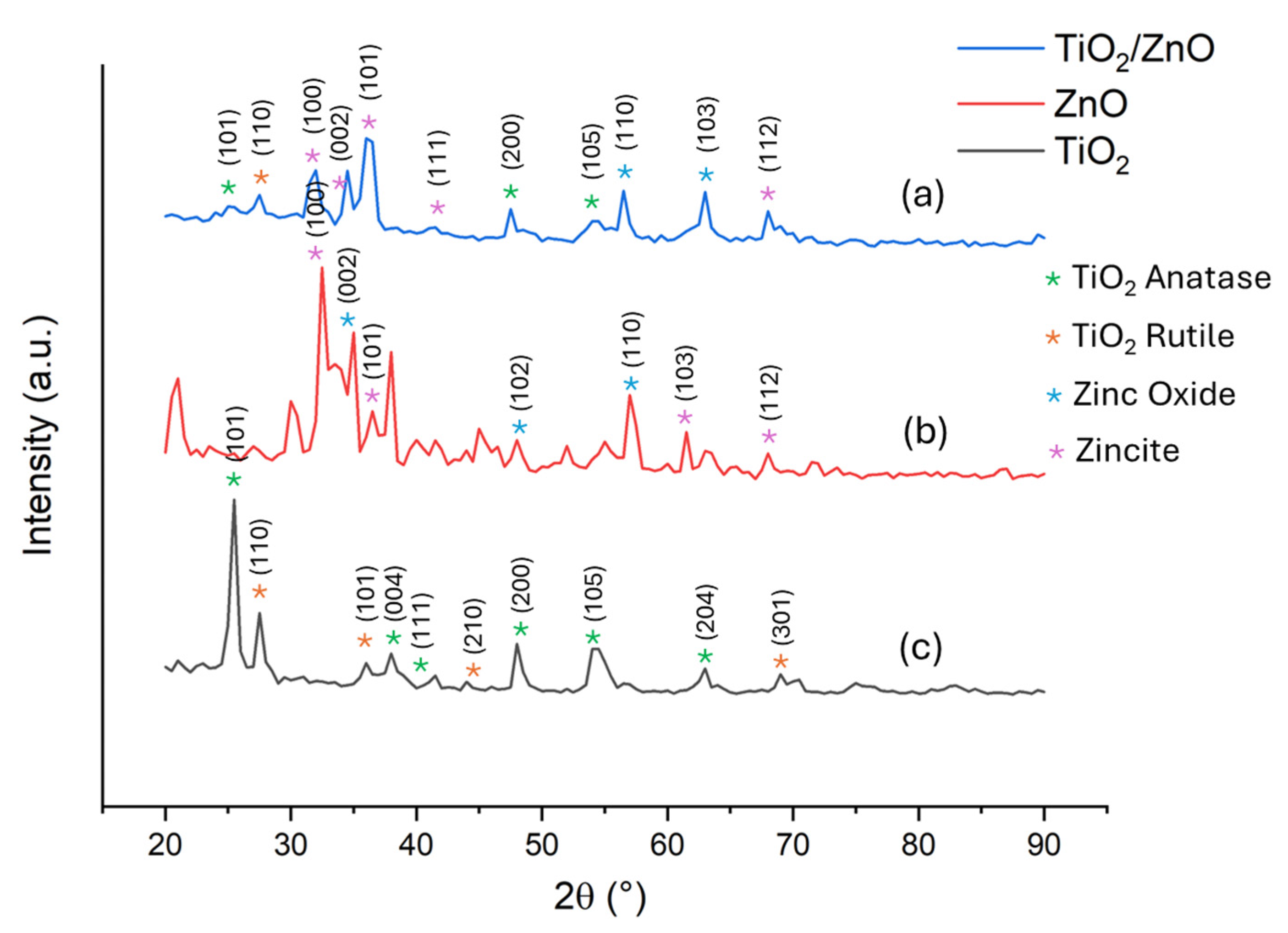
2.1.1. X-ray Diffractometry

XRD data show the formation of anatase (JCPDF card no. 21-1272) and rutile (JCPDF card no. 21-1276) crystal structures in the TiO2 sample (Figure 1a), zincite and zinc oxide (JCPDF card no. 36-1451) in the ZnO sample (Figure 1b) and all components in the TiO2/ZnO sample (Figure 1c). XRD patterns show a very good crystalline nature of TiO2, ZnO and TiO2/ZnO photocatalysts. For particle size determination, Scherrer equation was used.
For the TiO2 powder, two predominant peaks are identified, anatase (101), which intersects the a and c axes, and also rutile (110), which intersects the a and b axes. They are found at 2θ = 25.6° and 27.44°, respectively (Figure 1a). The average size of TiO2 crystallites is 127 nm. The strong characteristic (100) and (002) peaks at 2θ = 32.47° and 35.06° indicate the growth of ZnO nanostructures mainly along the a- (100) and c-axis (002) direction (Figure 1b). The average size of ZnO crystallites is 153 nm, slightly higher than that of the TiO2 sample. The TiO2/ZnO sample has the predominant peaks mentioned in Figure 1a,b for the TiO2 and ZnO samples, with the exception of anatase (101). In addition, the most predominant peak in this sample is zincite (101), which is found at 2θ = 36.30°. This sample has the smallest crystallite average size (87 nm); thus, it has the best properties. TiO2/ZnO is of high purity, as there are no unidentified peaks or peaks that correspond to other compounds.

2.1.2. X-ray Photoelectron Spectroscopy

The surface composition of the photocatalysts was assessed by carrying out X-ray photoelectron spectroscopy (XPS). XPS full spectra of the photocatalysts indicate the signals corresponding to Ti 2p, Zn 2p, O 1s and C 1s, with the last signal being associated with the preparation of the samples for analysis. The XPS surveys indicate pure synthetic photocatalysts, whereby the results obtained agree with those obtained by XRD analysis.
The valence states of the elements indicated by the XPS surveys are analyzed in the narrow spectra presented separately for each in Figure 2, Figure 3 and Figure 4. Thus, the binding energy for Ti 2p3/2 and Ti 2p1/2 into the TiO2 photocatalyst (Figure 2a) is 459.67 eV and 467.06 eV, respectively, which can most likely be attributed to Ti4+ ions in the oxide lattice of TiO2 [15,16]. In comparison, the spectrum of the TiO2/ZnO photocatalyst (Figure 2b) shows a shift towards lower binding energies for Ti 2p3/2, and towards higher binding energies for Ti 2p1/2, thus demonstrating a series of interactions between Ti and Zn in the oxide mixture [17]. The deconvolution of the peak corresponding to Ti 2p2/3 highlights two peaks, one at 458.54 eV and another at 456.68 eV, while the deconvolution of the peak corresponding to Ti 2p1/2 highlights two other peaks located at 466.11 eV and 469.23 eV. The peaks located at 458.54 eV and 469.23 eV were assigned to the 2p3/2 and 2p1/2 core levels of Ti4+, while the peaks at 456.68 eV and 466.11 eV were assigned to the 2p3/2 and 2p1/2 core levels of Ti3+. The peaks shifted (to lower binding energies of 2p3/2 core level and to higher binding energy of 2p1/2 core level) in the TiO2/ZnO photocatalyst could be due to the existence of oxygen vacancies (OV) around the Ti4+ ion, and therefore, the Ti3+ ion is most probably formed to compensate the charging requirement to establish the charge balance [18,19,20].
Figure 3 shows the deconvoluted spectrum of Zn 2p into ZnO and TiO2/ZnO photocatalysts. The peaks located at the binding energies of 1023 eV and 1046 eV (Figure 3a) are attributed to Zn 2p3/2 and Zn 2p1/2, respectively, which can be assigned to Zn2+ ions in oxide lattice of ZnO [21]. The peaks attributed to Zn 2p3/2 and Zn 2p1/2 in the TiO2/ZnO photocatalyst are shifted to lower values, again indicating a series of interactions between the two elements, namely Ti and Zn, in their oxide mixture. Thus, the peaks located at the binding energies of 1021.1 eV and 1044.62 eV (Figure 3b) are attributed to Zn 2p3/2 and Zn 2p1/2, respectively, and can be assigned to Zn2+ ions in oxide lattice of ZnO. The shoulder appearing within the Zn 2p2/3 peak reveals a new peak located at the binding energy of 1023.1 eV after deconvolution, which could indicate the presence of interstitial zinc ions surrounded by oxygen atoms [22].
The deconvoluted spectrum of O 1s into TiO2, ZnO and TiO2/ZnO photocatalysts are shown in Figure 4. The main two peaks of O 1s in the TiO2 photocatalyst (Figure 4a) are located at binding energies of 531.03 eV and 532.55 eV. They are attributed to oxygen in surface hydroxyl groups (Ti-OH) and to oxygen in adsorbed water molecules (Ti-H2O), respectively. The deconvoluted spectrum of the ZnO photocatalyst (Figure 4b) highlights the peak attributed to lattice oxygen in ZnO (Zn-O) at 530.21 eV, and the peak attributed to week bonds of oxygen on the surface hydroxyl groups (Zn-OH) at 531.87 eV [23,24].
The deconvoluted XPS spectrum of O 1s into TiO2/ZnO photocatalyst (Figure 4c) highlights three peaks located at the binding energies of 531.17 eV, 532.32 eV and 533.48 eV. The first peak is associated with the oxygen in surface hydroxyl groups (Ti-OH and Zn-OH), while the second and the third peaks are attributed to oxygen in adsorbed water molecules (Ti-H2O and Zn-H2O). Even if some of the peaks in the deconvoluted O 1s spectrum in the range of binding energies of 531–534 eV could be attributed to oxygen vacancies, which would justify the presence of Ti3+ in the deconvoluted spectrum of Ti 2p (the formation of surface Ti3+ is necessary for charge compensation in order to restore the charge balance of the lattice system), however, this attribution is uncertain because the XPS analysis was performed in ex-situ conditions, which expose the photocatalyst samples to ambient water vapor [25,26].

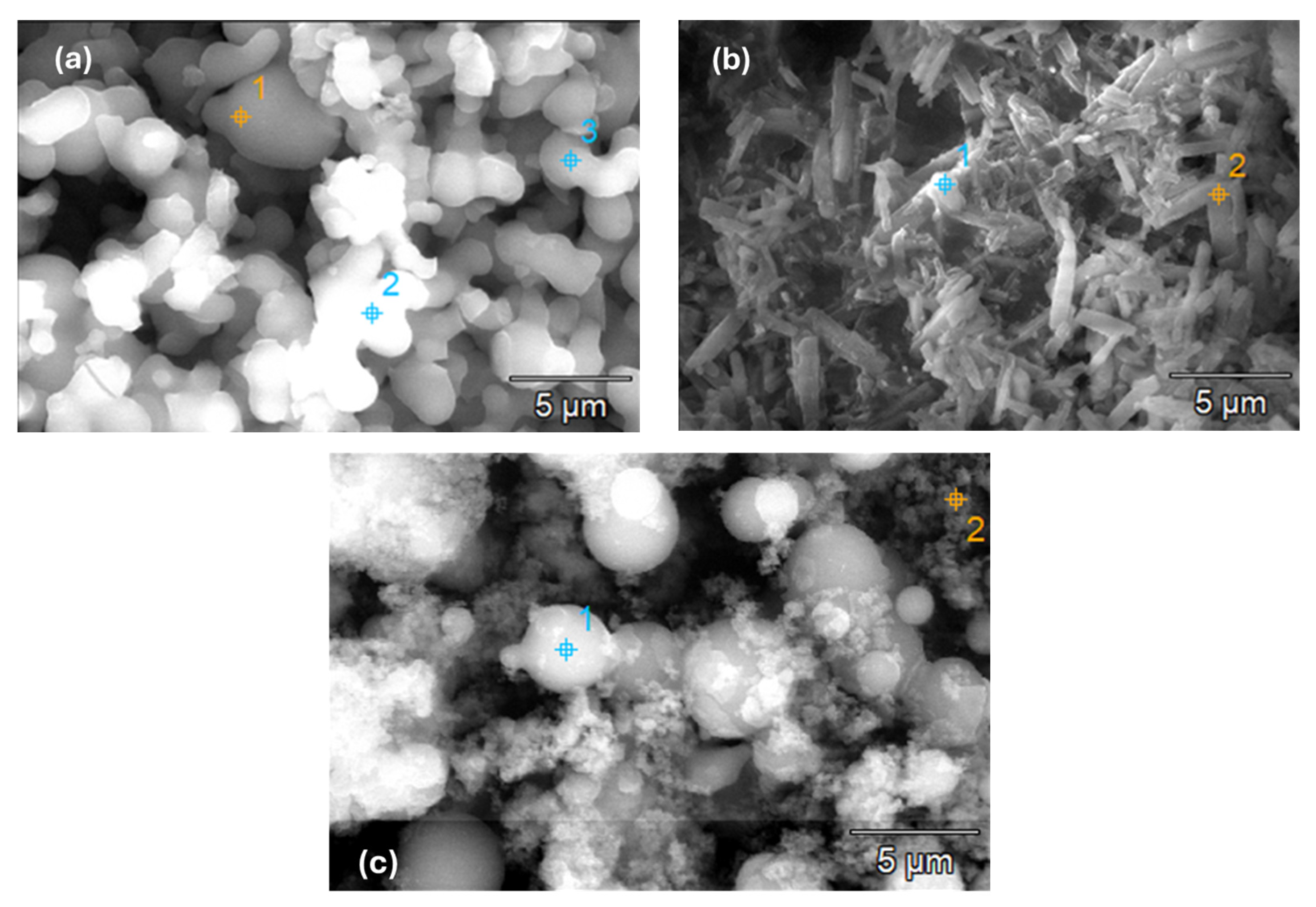
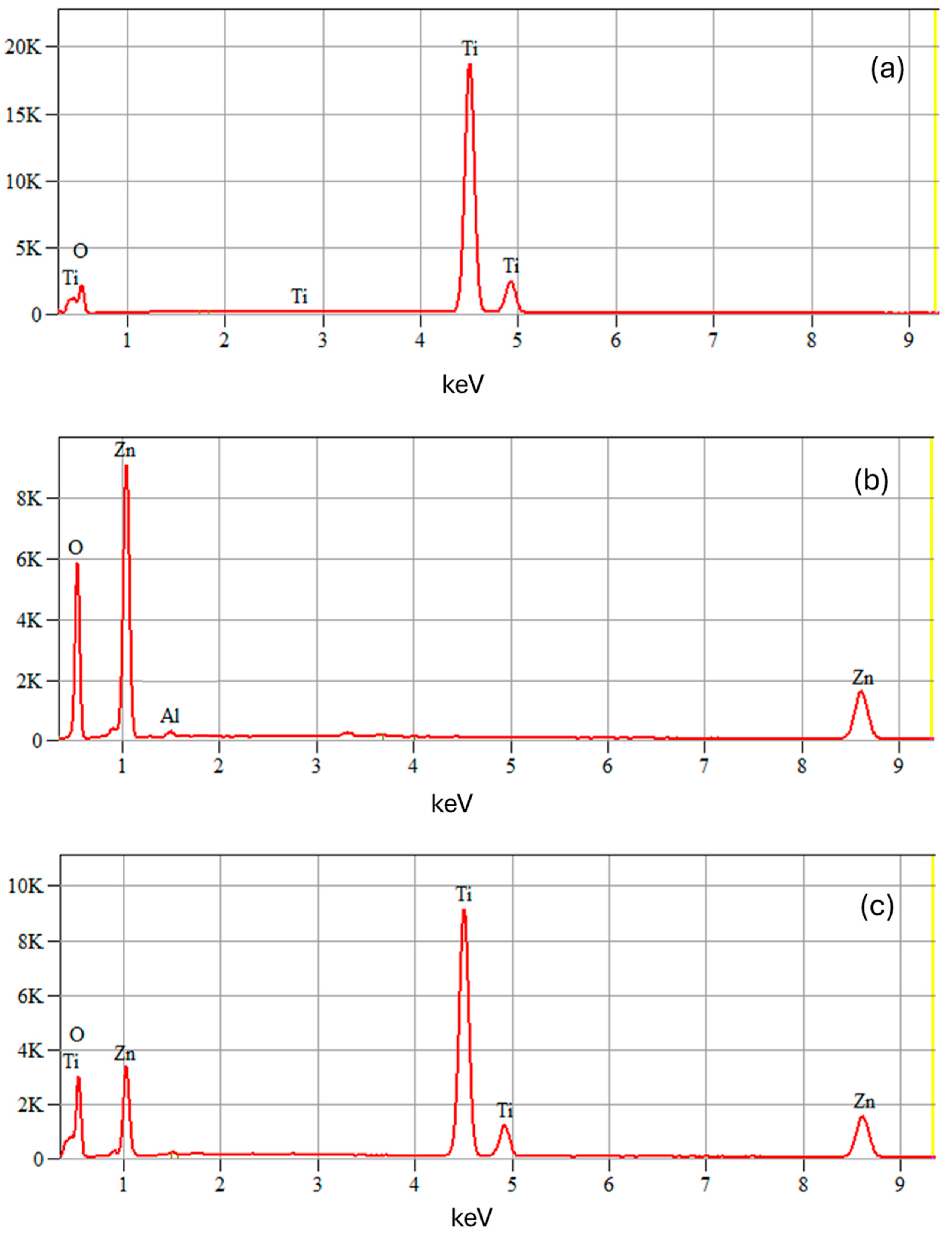
2.1.3. Scanning Electron Microscopy/Energy-Dispersive X-ray Spectroscopy

The morphology of the synthesized photocatalysts was examined by scanning electron microscopy (SEM); the results are shown in Figure 5. As can be seen, the TiO2 particles (Figure 5a) seem to be a mixture of spherical and slight irregularly shaped particles with different granulometries. In contrast, the ZnO particles appear to be rod-shaped, arranging themselves in aggregated structures (Figure 5b). The morphology of the TiO2/ZnO photocatalyst (Figure 5c) seems to be a combination of the two morphologies described above, with the mixture of spherical and slight irregularly shaped particles of TiO2 being interspersed with the rod-shaped particles of ZnO. This arrangement of the particles leads to a more compact structure of the TiO2/ZnO photocatalyst, in which the TiO2 and ZnO particles seem to adhere to each other, a fact that could lead to the appearance of specific interactions between them.
The EDX analysis (Figure 6) indicates only the presence of the constituent elements of the three types of photocatalysts, indicating the purity of these materials, which is in close agreement with the results obtained from the XRD and XPS analyses.

2.2. Photocatalytic Degradation of Estrogenic Mixture

The kinetics of the photocatalytic degradation of the estrogenic mixture estradiol valerate/norgestrel by using the three types of synthesized photocatalysts is shown in Figure 7, Figure 8 and Figure 9. It should be specified that, hereinafter, the entire organic content made up of the initial organic mixture of estrogens and the organic degradation intermediates formed will be generically referred to as the organic substrate. Thus, Figure 7 shows the evolution of the photocatalytic degradation of the organic substrate during the two hours of irradiation, using TiO2 as a photocatalyst. As can be seen, the overall degradation efficiency of the organic substrate increases with the increase in the number of photocatalytic modules (Figure 7a). It should be noted that the degradation of the organic substrate proceeds at a high speed during the first 10 to 30 min of the irradiation time (depending on the number of photocatalytic modules), after which, it decreases significantly and remains at low values throughout the time left of the irradiation time. These results indicate that the degradation kinetics of the organic substrate takes place in two stages. Most likely, in the first stage, the degradation of the organic substrate less resistant to the conditions in the reactor (strong oxidizing environment, acidic pH, and UV radiation) takes place, and later, the slow degradation of the organic substrate more resistant to these conditions occurs (probably, some organic intermediates formed). Thus, in the first 10 to 30 min of irradiation (the first stage of degradation), the degradation efficiency is approximately the same regardless of the number of photocatalytic modules, namely around 46% (46.0% for one photocatalytic module in 30 min of irradiation, 46.8% for two photocatalytic modules in 15 min of irradiation, and 46.4% for three photocatalytic modules in 10 min of irradiation), while, after the second stage of degradation (at the end of the irradiation time), the degradation efficiency is different depending on the number of photocatalytic reactors (54.0% for one photocatalytic module, 67.6% for two photocatalytic modules and 84.0% for three photocatalytic modules). The photocatalytic degradation of the organic substrate follows a pseudo-first-order kinetics (Equations (1) and (2)), which is valid for both degradation stages (Figure 7b) [27]:
Ct = C0e−kt
ln (C0/Ct) = kt
where k is a pseudo-first-order rate constant (min−1). The kinetic parameters of the photocatalytic degradation of the organic substrate by using TiO2 photocatalyst are shown in Table 1. As can be seen, the rate constant corresponding to the first stage of degradation is clearly much higher than the second stage of degradation.
Figure 8 shows the progress in the photocatalytic degradation of the organic substrate during the two hours of irradiation, using ZnO as a photocatalyst. The same trend is recorded in terms of the overall efficiency of photocatalytic degradation as in the case of the TiO2 photocatalyst, which increases with the increase in the number of photocatalytic modules. In the first stage of degradation, the efficiency is around 62% (62.4% for a photocatalytic module in 30 min of irradiation, 62.0% for two photocatalytic modules in 15 min of irradiation and 62.4% for three photocatalytic modules in 10 min of irradiation), while, at the end of the irradiation period, the degradation efficiency is 70.4% for one photocatalytic module, 79.6% for two photocatalytic modules and 91.2% for three photocatalytic modules. The photocatalytic degradation of the organic substrate also follows a pseudo-first-order kinetics valid for both degradation stages. The kinetic parameters of the photocatalytic degradation of the organic substrate by using ZnO photocatalyst are shown in Table 1. However, it should be noted that the degradation efficiency is higher than in the case of the TiO2 photocatalyst for both degradation stages. Also, the kinetic constants have higher values, highlighting the higher degradation rate.
In the case of the TiO2/ZnO photocatalyst (Figure 9), although the same tendency is maintained in terms of efficiency and degradation speed, it should be noted that the organic substrate is almost mineralized during the two hours of irradiation by using only two photocatalytic modules. In the first stage of degradation, the efficiency is around 72.5% (72.4% for a photocatalytic module in 15 min of irradiation and 73.2% for two photocatalytic modules in 10 min of irradiation), and in the second stage of degradation (at the end of the irradiation period), the efficiency is 84.8% for one photocatalytic module and 98.0% for two photocatalytic modules. The photocatalytic degradation of the organic substrate follows a pseudo-first-order kinetics for both degradation stages. The kinetic parameters (Table 1) indicate a clearly higher degradation rate compared to the other two photocatalysts, at least at the level of two photocatalytic modules.
The obtained results highlight the fact that the photocatalytic degradation efficiency of the organic substrate is a function of the dose of photocatalysts used, regardless of the type of photocatalyst. Taking into account the fact that the dose of photocatalyst is kept approximately constant for each individual photocatalytic module, it is found that with each photocatalytic module added, the dose of photocatalyst in the photocatalytic system becomes twice as high. If after the first stage of photocatalytic degradation the efficiency is approximately the same for a certain type of photocatalyst, regardless of the number of photocatalytic modules, after the second stage of photocatalytic degradation (at the end of the 120 min of irradiation), efficiency increases constantly with the addition of photocatalytic modules. In this respect, for the TiO2 photocatalyst, the efficiency is 1.14 higher after each added photocatalytic module; for the ZnO photocatalyst, it is 1.25 higher; and for the TiO2/ZnO photocatalyst, it is 1.15 higher. Having this information available, the dose of photocatalyst can be determined in terms of the number of photocatalytic modules required for the complete mineralization of a certain type of organic substrate. Thus, the results clearly indicate that, for the initial organic substrate consisting of estrogenic mixture estradiol valerate/norgestre, the addition of a fourth photocatalytic module in the case of systems with TiO2 or ZnO photocatalyst would result in complete mineralization of the organic substrate in the same irradiation time of 120 min, but using a higher dose of photocatalyst. Therefore, this result confirms the superior performance of the TiO2/ZnO photocatalyst in terms of photocatalytic activity (complete mineralization with only two photocatalytic modules compared to the need for four photocatalytic modules for the other two photocatalytic systems).
Figure 10 shows the cycling test results for the photocatalyst for which the best degradation efficiency was obtained, namely TiO2/ZnO. It should be mentioned that a fresh solution of estrogenic mixture was used in each run. As can be seen, the degradation efficiency remains approximately constant (98.0% for the first run, 97.2% for the second run, 97.6% for the third run and 98.4% for the fourth run), which highlights a high stability of the photocatalyst deposited on the glass spheres, as well as keeping its photocatalytic activity for a long period of irradiation.

3. Materials and Methods

3.1. Materials

The estrogenic mixture estradiol valerate/norgestrel derived from Cyclo-Progynova pharmaceutical formulation (pills containing 2 mg estradiol valerate and 0.5 mg norgestrel) from Bayer (Bayer AG, Leverkusen, Germany) was purchased from a local human pharmacy. Titanium(IV) isopropoxide (TTIP) 97%, zinc acetate dihydrate 98%, ethanol absolute 99.9%, and nitric acid 65%, all of analytical grade, were purchased from Sigma-Aldrich (Darmstadt, Germany), and used for photocatalyst synthesis. Hydrogen peroxide solution of 30% was purchased from Sigma-Aldrich and used in the photocatalysis tests.
The photocatalytic modules consist of quartz tubes with the dimensions 5 cm (d) × 10 cm (h), and the inert support on which the photocatalyst is deposited consists of perforated glass balls of 4 mm (d), so that they can be strung on stainless-steel wires. The photocatalytic modules are interconnected using the garden hose pipe fittings kit so they can be easily added or removed from the photocatalytic system. All these materials were purchased from various local companies (Bucharest, Romania).

3.2. Synthesis of Photocatalysts and Their Deposition on the Inert Support

3.2.1. TiO2 Photocatalyst

TiO2 photocatalyst was synthesized through the sol–gel method, which, in short, consists of the dropwise addition of an aqueous solution of nitric acid (1.3% by mass) over a solution of titanium(IV) isopropoxide (TTIP) in absolute ethanol (AE) at an AE/TTIP volume ratio of 3 (pre-mixed for one hour) under continuous stirring at a temperature of 60 °C (the temperature was chosen to be below the boiling point of the solvent) for two hours. It should be noted that the photocatalyst was deposited directly from the solution on the inert support, and therefore, the glass balls strung on rows of stainless-steel wires were immersed in the opaque and viscous mixture formed for one hour, after which they were kept in the oven at a temperature of 105 °C to remove the solvent for 24 h. Finally, the rows of glass balls were calcined at a temperature of 500 °C for four hours (the temperature was chosen to be below the limit of the glass transition temperature of the glass support).

3.2.2. ZnO Photocatalyst

ZnO photocatalyst was also synthesized by the sol–gel method, which, in short, consists of mixing 3 g of zinc acetate dihydrate with a solution consisting of absolute ethanol (EA) and nitric acid (NA) at an EA/NA volumetric ratio of 2, under continuous stirring for 10 min. Next, the glass balls strung on rows of stainless-steel wires were immersed in the obtained solution for one hour, kept in the oven at a temperature of 105 °C for 24 h, and calcined at a temperature of 500 °C for four hours.

3.2.3. TiO2/ZnO Photocatalyst

For the synthesis of the TiO2/ZnO photocatalyst, the opaque and viscous solution obtained in the synthesis of the TiO2 photocatalyst is mixed with the solution obtained in the synthesis of the ZnO photocatalyst (both syntheses described above) under continuous stirring for two hours at a temperature of 60 °C. Next, the glass balls strung on rows of stainless-steel wires were immersed in the new mixture obtained for one hour, kept in the oven at a temperature of 105 °C for 24 h, and calcined at a temperature of 500 °C for four hours.

3.3. Photocatalytic Experiments

The photocatalytic experiments were carried out in modular photocatalytic systems designed so that the number of photocatalytic modules can be easily changed. The photocatalytic modules, which are made from quartz tubes with the dimensions 5 cm (d) × 10 cm (h), are operated in a plug flow reactor system under a UV-A radiation field, and the photocatalyst (TiO2, ZnO or TiO2/ZnO) is immobilized on an inert support of glass balls (4 mm in diameter) that are strung on stainless-steel wire and arranged in rows along the photocatalytic modules. It should be noted that the glass balls were initially cleaned by washing with an oxidizing mixture (potassium dichromate in concentrated sulfuric acid), rinsing with pure water several times, followed by washing with pure water in an ultrasonic field (37 kHz, Ultrasonic Bath Elmasonic Select 60 (Elma Schmidbauer GmbH, Singen, Germany). There are 65 glass balls on a string of stainless-steel wire, and a photocatalytic module contains 6 strings. The average amount of photocatalyst deposited on the inert support of a photocatalytic module is 1g (0.92 g–1.15 g). The photocatalytic modules are interconnected by using the garden hose pipe fittings kit and are continuously fed for two hours at room temperature through a feeding vessel using a peristaltic pump (LBX Pump-60J-001, Labbox Labware, S.L., Barcelona, Spain). The radiation source (Osram L Blue UV-A 18 W/78 G13 lamps, OSRAM GmbH, München, Germany) surrounds the modular photocatalytic system in such a way that each photocatalytic module receives an approximately equal amount of radiation (around 2400 μw/cm2, measured with a Cole-Parmer UV-meter with mobile probe from General Tools & Instruments (General Tools & Instruments LLC, New York, NY, USA)). A schematic of the modular photocatalytic system is shown in Figure 11.
The conditions in which the photocatalytic system was operated are the following: a flow rate of the working solution of 20 L/h, pH 3 of the working solution, the volume of the working solution was 2 L, the initial concentration of the organic substrate in the aqueous working solution was 250 mg O2/L (Chemical Oxygen Demand—COD equivalent concentration), and a hydrogen peroxide/organic substrate mass ratio of 1. It should be noted that these working conditions were chosen after performing some preliminary tests. In order to monitor the degree of removal of the organic substrate during the two hours of irradiation, samples were taken from the feed vessel at predetermined times and subjected to COD analysis according to the APHA 5220 D standard method (closed reflux, colorimetric method) by using a Hach LT 200 thermostat and Hach DR 3800 spectrophotometer (Hach, Loveland, CO, USA).

3.4. Photocatalysts Characterization

The crystalline structure of the synthetized photocatalysts was investigated by XRD analysis using a Rigaku MiniFlex 600 X-ray diffractometer (Rigaku Holdings Corporation Tokyo, Japan), with a scan in the 20–90° 2θ range. Cu Kα monochromatic radiation was used as the X-ray source, with a characteristic wavelength of λ = 1.54 Å. Chemical compositions and valence-band spectra of the photocatalysis were investigated by XPS analysis using a Thermo Scientific K-Alpha instrument (Thermo Fisher Scientific Inc., Waltham, MA, USA) with a monochromate Al Kα source on a spot size of 400 μm. The binding energy scan range was 0–1361 eV in 1 eV steps, and the pass energy was 200 eV. Binding energies were calibrated by placing the C 1 s peak at 284.4 eV. The morphology and elemental analyses of the synthetized photocatalysts were performed by using a QUANTA 450 FEG electron microscope (FELMI-ZFE, Graz, Austria) coupled with an EDS detector operated at an accelerating voltage of 30 kV.

4. Conclusions

The experimental results of this work highlighted the following:
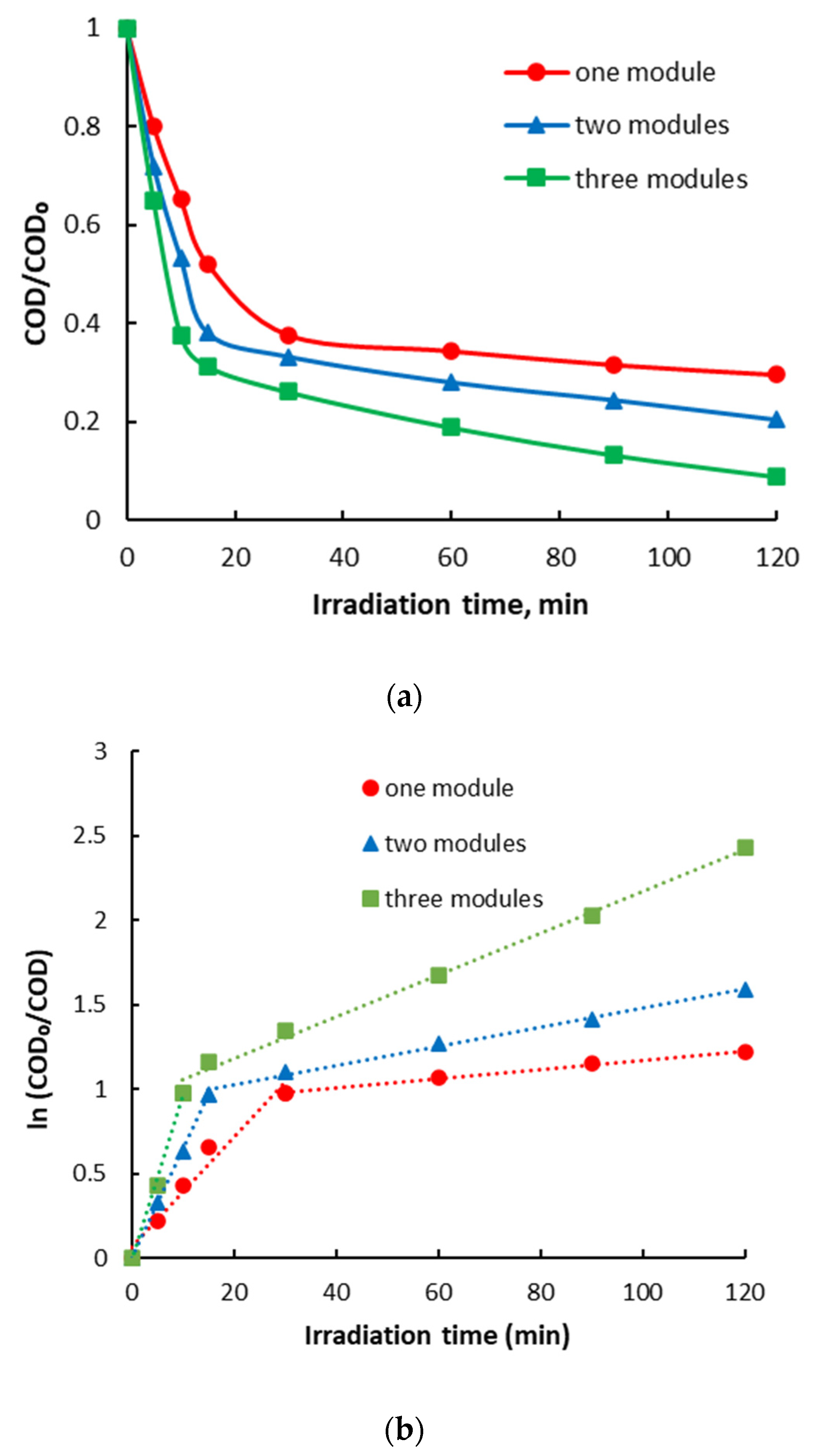
The photocatalytic degradation efficiency of the organic substrate, initially formed from the estrogenic estradiol valerate/norgestrel mixture, largely depends on the dose of photocatalyst used regardless of its type. The dose can be easily modified by adding or removing photocatalytic modules that contain approximately the same amount of photocatalysts.
The photocatalytic degradation of the organic substrate takes place in two stages with different speeds but following the same type of kinetics, namely pseudo-first-order kinetics. The number of photocatalytic modules required for the complete mineralization of a certain type of organic substrate can be determined based on the results obtained in the second stage of photocatalytic degradation in terms of degradation efficiency.
The best results in terms of photocatalytic degradation efficiency were obtained for the photocatalytic system with a TiO2/ZnO-type photocatalyst. The organic substrate was almost completely mineralized in 120 min of irradiation with only two photocatalytic modules.
The morphological, mineralogical and spectroscopic analyses showed that the synthesized photocatalysts are of high purity, and that the high performance of the TiO2/ZnO photocatalyst is due to its superior characteristics such as small crystallites, compact structure and highly reactive specific surface. The manifestation of specific interactions between the elements that form the oxide mixture leads to the appearance of surface defects beneficial to charge transfer, and thus, to photocatalytic activity.

Author Contributions

Conceptualization, C.B. and L.B.; methodology, L.B. and C.O.; formal analysis, G.I.I., E.I.B., A.C., E.M. and A.C.B.; investigation, C.O., C.P., C.B. and L.B.; resources, L.B. and C.O.; writing—original draft preparation, C.B., L.B., C.O. and C.P.; writing—review and editing, C.B., L.B. and C.O.; supervision, C.B. and C.O.; project administration, L.B.; funding acquisition, L.B. All authors have read and agreed to the published version of the manuscript.

Funding

This research was funded by the National Program for Research of the National Association of Technical Universities—GNAC ARUT 2023, grant no. 65/10.10.2023.

Data Availability Statement

The raw data supporting the conclusions of this article will be made available by the authors on request.

Conflicts of Interest

The authors declare no conflicts of interest. The funders had no role in the design of the study; in the collection, analyses, or interpretation of data; in the writing of the manuscript; or in the decision to publish the results.

References

  1. Yang, X.; He, X.; Lin, H.; Lin, X.; Mo, J.; Chen, C.; Dai, X.; Liao, D.; Gao, C.; Li, Y. Occurrence and distribution of natural and synthetic progestins, androgens, and estrogens in soils from agricultural production areas in China. Sci. Total Environ. 2021, 751, 141766. [Google Scholar] [CrossRef]
  2. Aubead, N.M. Role of Sex Hormones in Human Body. In Reproductive Hormones; Marsh, C., Ed.; IntechOpen: Kansas City, MO, USA, 2021. [Google Scholar] [CrossRef]
  3. Amenyogbe, E.; Chen, G.; Wang, Z.; Lu, X.; Lin, M.; Lin, A.I. A Review on Sex Steroid Hormone Estrogen Receptors in Mammals and Fish. Int. J. Endocrinol. 2020, 2020, 5386193. [Google Scholar] [CrossRef] [PubMed]
  4. Zhao, X.; Grimes, K.L.; Colosi, L.M.; Lung, W.-S. Attenuation, transport, and management of estrogens: A review. Chemosphere 2019, 230, 462–478. [Google Scholar] [CrossRef] [PubMed]
  5. Li, N.; Li, J.; Zhang, Q.; Gao, S.; Quan, X.; Liu, P.; Xu, C. Effects of endocrine disrupting chemicals in host health: Three-way interactions between environmental exposure, host phenotypic responses, and gut microbiota. Environ. Pollut. 2021, 271, 116387. [Google Scholar] [CrossRef]
  6. Directive 2013/39/EU of the European Parliament and of the Council of 12 August 2013 Amending Directives 2000/60/EC and 2008/105/EC as Regards Priority Substances in the Field of Water Policy Text with EEA Relevance. OJ L 226. 2013, pp. 1–17. Available online: http://data.europa.eu/eli/dir/2013/39/oj (accessed on 9 July 2024).
  7. Commission Implementing Decision (EU) 2018/840 of 5 June 2018 Establishing a Watch List of Substances for Union-Wide Monitoring in the Field of Water Policy Pursuant to Directive 2008/105/EC of the European Parliament and of the Council and Repealing Commission Implementing Decision (EU) 2015/495 (Notified under Document C(2018) 3362). OJ L 141. 2018, pp. 9–12. Available online: http://data.europa.eu/eli/dec_impl/2018/840/oj (accessed on 9 July 2024).
  8. Commission Implementing Decision (EU) 2022/679 of 19 January 2022 Establishing a Watch List of Substances and Compounds of Concern for Water Intended for Human Consumption as Provided for in Directive (EU) 2020/2184 of the European Parliament and of the Council (Notified under Document C(2022) 142). OJ L 124. 2022, pp. 41–43. Available online: http://data.europa.eu/eli/dec_impl/2022/679/oj (accessed on 9 July 2024).
  9. Coello-Garcia, T.; Curtis, T.P.; Mrozik, W.; Davenpor, R.J. Enhanced estrogen removal in activated sludge processes through the optimization of the hydraulic flow pattern. Water Res. 2019, 164, 114905. [Google Scholar] [CrossRef] [PubMed]
  10. Bilal, M.; Rizwan, K.; Adeel, M.; Barceló, D.; Awad, Y.A.; Iqbal, H.M.N. Robust strategies to eliminate endocrine disruptive estrogens inwater resources. Environ. Pollut. 2022, 306, 119373. [Google Scholar] [CrossRef]
  11. Al-Nuaim, M.A.; Alwasiti, A.A.; Shnain, Z.Y. The photocatalytic process in the treatment of polluted water. Chem. Pap. 2023, 77, 677–701. [Google Scholar] [CrossRef]
  12. Joseph, A.; Vijayanandan, A. Review on support materials used for immobilization of nano-photocatalysts for water treatment applications. Inorganica Chim. Acta 2023, 545, 121284. [Google Scholar] [CrossRef]
  13. Huang, H.J.; Wu, J.C.-S.; Chiang, H.-P.; Chau, Y.-F.C.; Lin, Y.-S.; Wang, Y.H.; Chen, P.-J. Review of Experimental Setups for Plasmonic Photocatalytic Reactions. Catalysts 2020, 10, 46. [Google Scholar] [CrossRef]
  14. Visan, A.; van Ommen, J.R.; Kreutzer, M.T.; Lammertink, R.G.H. Photocatalytic Reactor Design: Guidelines for Kinetic Investigation. Ind. Eng. Chem. Res. 2019, 58, 5349–5357. [Google Scholar] [CrossRef]
  15. Erdem, B.; Hunsicker, R.A.; Simmons, G.W.; Sudol, E.D.; Dimonie, V.L.; El-Aasser, M.S. XPS and FTIR Surface Characterization of TiO2 Particles Used in Polymer Encapsulation. Langmuir 2001, 17, 2664–2669. [Google Scholar] [CrossRef]
  16. Kubiak, A.; Żółtowska, S.; Bartkowiak, A.; Gabała, E.; Sacharczuk, N.; Zalas, M.; Siwińska-Ciesielczyk, K.; Jesionowski, T. The TiO2-ZnO Systems with Multifunctional Applications in Photoactive Processes—Efficient Photocatalyst under UV-LED Light and Electrode Materials in DSSCs. Materials 2021, 14, 6063. [Google Scholar] [CrossRef] [PubMed]
  17. Saad, S.K.M.; Umar, A.A.; Nguyen, H.Q.; Dee, C.F.; Salleh, M.M.; Oyama, M. Porous (001)-faceted Zn-doped anatase TiO2 nanowalls and their heterogeneous photocatalytic characterization. RSC Adv. 2014, 4, 57054. [Google Scholar] [CrossRef]
  18. Ohno, T.; Tsubota, T.; Toyofukum, M.; Inaba, R. Preparation of S-doped TiO2 Photocatalysts and their Photocatalytic Activities Under Visible Light. Appl. Catal. A Gen. 2004, 265, 255–258. [Google Scholar] [CrossRef]
  19. Pandey, S.K.; Pandey, S.K.; Mukherjee, C.; Mishra, P.; Gupta, M.; Barman, S.R.; D’Souza, S.W.; Mukherjee, S. Effect of growth temperature on structural, electrical and optical properties of dual ion beam sputtered ZnO thin films. J. Mater. Sci. Mater. Electron. 2013, 24, 2541–2547. [Google Scholar] [CrossRef]
  20. Fu, R.; Wang, Q.; Gao, S.; Wang, Z.; Huang, B.; Dai, Y.; Lu, J. Effect of different processes and Ti/Zn molar ratios on the structure, morphology, and enhanced photoelectrochemical and photocatalytic performance of Ti3+ self-doped titanium–zinc hybrid oxides. J. Power Sources 2015, 285, 449–459. [Google Scholar] [CrossRef]
  21. Krylova, G.; Brioude, A.; Ababou-Girard, S.; Mrazeka, J.; Spanhel, L. Natural superhydrophilicity and photocatalytic properties of sol-gel derived ZnTiO3-ilmenite/r-TiO2 films. Chem. Phys. 2010, 12, 15101–15110. [Google Scholar] [CrossRef]
  22. Kumar, A.; Ahmad, M.I. Role of defects and microstructure on the electrical properties of solution-processed Al-doped ZnO transparent conducting films. Appl. Phys. A 2020, 126, 598. [Google Scholar] [CrossRef]
  23. Fan, C.; Chen, C.; Wang, J.; Fu, X.; Ren, Z.; Qian, G.; Wang, Z. Black Hydroxylated Titanium Dioxide Prepared Via Ultrasonication with Enhanced Photocatalytic Activity. Sci. Rep. 2015, 5, 11712. [Google Scholar] [CrossRef]
  24. Claros, M.; Setka, M.; Jimenez, Y.; Vallejos, S. AACVD Synthesis and Characterization of Iron and Copper Oxides Modified ZnO Structured Films. Nanomaterials 2020, 10, 471. [Google Scholar] [CrossRef]
  25. Idriss, H. On the wrong assignment of the XPS O1s signal at 531–532 eV attributed to oxygen vacancies in photo- and electro-catalysts for water splitting and other materials applications. Surf. Sci. 2021, 712, 121894. [Google Scholar] [CrossRef]
  26. Frankcombe, T.J.; Liu, Y. Interpretation of Oxygen 1s X-ray Photoelectron Spectroscopy of ZnO. Chem. Mater. 2023, 35, 5468–5474. [Google Scholar] [CrossRef]
  27. Li, B.; Yuan, D.; Gao, C.; Zhang, H.; Li, Z. Synthesis and characterization of TiO2/ZnO heterostructural composite for ultraviolet photocatalytic degrading DOM in landfill leachate. Environ. Sci. Pollut. Res. 2022, 29, 85510–85524. [Google Scholar] [CrossRef] [PubMed]
Figure 1. XRD patterns for the synthetized photocatalysts: (a) TiO2, (b) ZnO and (c) TiO2/ZnO.
Catalysts 14 00661 g001
Figure 2. Deconvoluted XPS spectrum of Ti 2p: (a) Ti 2p into TiO2; (b) Ti 2p into TiO2/ZnO.
Catalysts 14 00661 g002
Figure 3. Deconvoluted XPS spectrum of Zn 2p: (a) Zn 2p into ZnO; (b) Zn 2p into TiO2/ZnO.
Catalysts 14 00661 g003
Figure 4. Deconvoluted XPS spectrum of O 1s: (a) O 1s into TiO2; (b) O 1s into ZnO; (c) O 1s into TiO2/ZnO.
Catalysts 14 00661 g004
Figure 5. Scanning electron microscopy images (SEM) of: (a) TiO2, (b) ZnO and (c) TiO2/ZnO. The numbers and points of different colors in the SEM images correspond to the areas where the EDX analysis was performed.
Catalysts 14 00661 g005
Figure 6. Elemental analysis (EDX) of: (a) TiO2, (b) ZnO and (c) TiO2/ZnO.
Catalysts 14 00661 g006
Figure 7. Kinetics of the photocatalytic degradation of the estrogen formulation by using TiO2 photocatalyst: (a) degradation of the organic substrate during the irradiation time; (b) pseudo-first-order kinetic model. Experimental conditions: flow rate 20 L/h, pH 3, working solution volume 2 L, initial concentration of the organic substrate 250 mg O2/L, estradiol valerate concentration 1 mg/L, norgestrel concentration 0.25 mg/L, photocatalyst concentration 1.5 g/L.
Catalysts 14 00661 g007aCatalysts 14 00661 g007b
Figure 8. Kinetics of the photocatalytic degradation of the estrogen formulation by using ZnO photocatalyst: (a) degradation of the organic substrate during the irradiation time; (b) pseudo-first-order kinetic model. Experimental conditions: flow rate 20 L/h, pH 3, working solution volume 2 L, initial concentration of the organic substrate 250 mg O2/L, estradiol valerate concentration 1 mg/L, norgestrel concentration 0.25 mg/L, and photocatalyst concentration 1.5 g/L.
Catalysts 14 00661 g008
Figure 9. Kinetics of the photocatalytic degradation of the estrogen formulation by using TiO2/ZnO photocatalyst: (a) degradation of the organic substrate during the irradiation time; (b) pseudo-first-order kinetic model. Experimental conditions: flow rate 20 L/h, pH 3, working solution volume 2 L, initial concentration of the organic substrate 250 mg O2/L, estradiol valerate concentration 1 mg/L, norgestrel concentration 0.25 mg/L, and photocatalyst concentration 1 g/L.
Catalysts 14 00661 g009
Figure 10. Cycling test of the photocatalytic degradation of the estrogen formulation by using TiO2/ZnO photocatalyst. Experimental conditions: flow rate 20 L/h, pH 3, working solution volume 2 L, initial concentration of the organic substrate 250 mg O2/L, estradiol valerate concentration 1 mg/L, norgestrel concentration 0.25 mg/L, and photocatalyst concentration 1 g/L.
Catalysts 14 00661 g010
Figure 11. (a) Sketch of the modular photocatalytic reactor (two photocatalytic modules). (b) Photo of the real modular photocatalytic reactor (three photocatalytic modules).
Catalysts 14 00661 g011
Table 1. Kinetic parameters of the photocatalytic degradation of the organic substrate.
PhotocatalystOne ModuleTwo ModulesThree Modules
k, min−1
TiO21st stage0.02070.04180.0624
2nd stage0.00180.00450.0101
ZnO1st stage0.03240.06410.0978
2nd stage0.00270.00570.0124
TiO2/ZnO1st stage0.08380.1317-
2nd stage0.00600.0230-
Disclaimer/Publisher’s Note: The statements, opinions and data contained in all publications are solely those of the individual author(s) and contributor(s) and not of MDPI and/or the editor(s). MDPI and/or the editor(s) disclaim responsibility for any injury to people or property resulting from any ideas, methods, instructions or products referred to in the content.

