Article

Synthesis, Magnetic, and Photocatalytic Activity of Polypyrrole-Based TiO2–Fe Catalyst for Wastewater Treatment

by
Muhammad Khalid Nazir
1,†,
Sana Javaid
2,†,
Hina Afzal
3,
Muhammad Babar Taj
3,*,
Doaa F. Baamer
4,
Afaf Almasoudi
4,
Reema H. Aldahiri
5,
Omar Makram Ali
6,
Muhammad Imran Khan
7,*,
Muhammad Mahboob Ahmed
1,
Abdallah Shanableh
7,8 and
Javier Fernandez-Garcia
9,10
1
Institute of Chemical Sciences, Bahauddin Zakariya University, Multan 60800, Pakistan
2
Institute of Physics, The Islamia University of Bahawalpur, Bahawalpur 63100, Pakistan
3
Institute of Chemistry, The Islamia University of Bahawalpur, Bahawalpur 63100, Pakistan
4
Chemistry Department, Faculty of Science, King Abdulaziz University, P.O. Box 42734, Jeddah 21589, Saudi Arabia
5
Department of Chemistry, College of Science, University of Jeddah, Jeddah 21959, Saudi Arabia
6
Department of Chemistry, Taraba University College, Taraba Branch, Taif University, P.O. Box 11099, Taif 21944, Saudi Arabia
7
Research Institute of Sciences and Engineering (RISE), University of Sharjah, Sharjah 27272, United Arab Emirates
8
Scientific Research Center, Australian University, Mubarak Al-Abdullah 40250, Kuwait
9
IQS School of Engineering, Universitat Ramon Llull, Via Augusta 390, 08017 Barcelona, Spain
10
Department of Chemical Engineering, University College London, Torrington Place, London WC1E 7JE, UK
*
Authors to whom correspondence should be addressed.
These authors contributed equally to this work.
Catalysts 2024, 14(10), 692; https://doi.org/10.3390/catal14100692 (registering DOI)
Submission received: 25 August 2024 / Revised: 25 September 2024 / Accepted: 1 October 2024 / Published: 5 October 2024
(This article belongs to the Section Photocatalysis)

Abstract

:
The primary aim of this study is to investigate the degradation efficacy of the Ppy/TiO2-Fe photocatalyst for MB dye in an aqueous solution. Firstly, the direct addition of TiO2 and Fe was done to prepare Ppy/TiO2-Fe photocatalyst. Fourier transformation infrared spectroscopy, XRD, SEM, BET surface area analysis, and magnetization tests established the formation of the Ppy/TiO2-Fe photocatalyst. The crystallite sizes of TiO2, Fe-TiO2, and Ppy/TiO2-Fe photocatalyst were estimated to be 24.99 nm, 21.94 nm, and 21.84 nm, respectively. For the synthesis confirmation, the FTIR spectrum confirmed the existence of Ti-O, Fe-O, and Ppy-related bonds. While comparing the SEM images, the impact of polypyrrole on the particle shape was observed with less aggregation and increased surface roughness. The VSM analysis revealed that incorporating polypyrrole (Ppy) into Fe-TiO2 significantly enhances its magnetic properties, with Ppy/TiO2-Fe exhibiting superparamagnetic behavior, characterized by a higher saturation magnetization (Ms) of 33.11 emu/g and a lower coercivity (Hc) of 0.160 Oe, compared to Fe-TiO2’s Ms of 1.09 emu/g and Hc of 341.39 Oe. The N2 sorption desorption, with a specific surface area of 2.25 × 10² m2/g, is beneficial for photocatalytic activity. The concentration of dye, amount of catalyst, pH, and temperature were studied to evaluate the photocatalytic efficiency of the synthesized Ppy/TiO2-Fe photocatalyst under different conditions. The findings revealed a degradation efficiency of 91.92%. The degradation rate reached 91.92% under optimal conditions within 120 min and could be fitted well by first-order kinetics. The photocatalytic efficiency was also evaluated for the scavenger, and the concentration of H2O2 and the reusability of the catalyst were demonstrated. Based on the observed results, the Ppy/TiO2-Fe photocatalyst could be applied more effectively and efficiently to photocatalytic degradation of organic dyes in wastewater treatment.

1. Introduction

Industrialization has significantly raised the levels of pollutants released into the environment [1]. When municipal and industrial wastes are discarded into water bodies, it leads to water pollution [2]. Industries often discharge untreated or partially treated wastewater into the environment, causing water and soil pollution. Many sectors, including pharmaceuticals, textiles, food production, paper and pulp, and cosmetics, rely on synthetic dyes in their manufacturing processes. In particular, the textile industry’s dyeing procedures consume vast amounts of water for fixing, dyeing, and washing [3]. A dye is an organic compound that absorbs visible light, giving it color, and it can bond strongly to fibers through chemical or physical interactions. For commercial use, dyes must be highly responsive to visible light, resistant to rubbing, and water-fast [4]. Because of their complex structure and ability to dissolve in water, these dyes resist degradation by traditional physicochemical methods [5,6,7]. The biodegradation products of these aromatic dyes are conjugated and accumulate in the environment, causing health effects to humans. Methylene blue is a low molecular weight, extensively conjugated aromatic cationic dye, as seen in Figure 1. Aromatic chemicals and amines, which are highly carcinogenic and cause histamine poisoning, are its breakdown products [8].
Various methods, including adsorption, coagulation, flocculation, and photocatalytic degradation, are commonly used to remove organic compounds. However, traditional degradation methods often prove ineffective [9]. Among these methods, photocatalysis is promising because it is cost-effective, easy to operate, recyclable, and environmentally friendly [10]. Photocatalysis, a type of AOP, has garnered significant attention because of its potential for economical commercial application. AOPs, or advanced oxidation processes, have been proposed as a possible fix. These procedures produce reactive free radicals that can mineralize organic substances and stop waste from forming [8,9,11].
A successful approach to dye removal involves using nano semiconductors like TiO2, ZnO, Fe2O3, and CdS. These materials are highly effective in photo-catalytically breaking down various organic contaminants without converting the primary pollutants into additional toxic substances [12]. Recently, nano titanium oxide has been recognized as a highly effective photocatalyst for degrading and removing various toxic organic pollutants [13,14]. These qualities make it highly effective, including stable chemical formula, biocompatibility, extreme oxidation capability, non-hazardous, and cheap to use [15,16]. The ability to degrade pollution by TiO2 under irradiation by weak UV and visible light was one of the means to widen the application of heterogeneous photocatalysis. The TiO2 multi-composite photocatalysts were synthesized for adsorption through N doping and N and Fe2O3 co-doping. The activity of these photocatalysts was determined by the degradation of methyl-orange under visible illumination. Using UV-Vis diffuse reflectance spectroscopy, X-ray diffraction, X-ray photoelectron spectroscopy, and photoluminescence spectra, the changes in the light absorption and the visible response enlargement of the catalysts under various conditions were investigated by changing sintering temperature, doping content of N, and co-doping. After that, the variations of the photocatalytic activities were studied in the condition of the irradiation of weak light. The outcomes indicated that the photocatalytic activity of the catalysts illuminated by UV-weak light had been significantly improved due to N doping, which could enhance the light absorption of the catalysts [17].
When exposed to UV light or sunlight, titanium dioxide (TiO2) catalyzes photodegradation, transforming organic compounds into harmless by-products such as carbon dioxide and water. This makes TiO2 nanoparticles highly effective in photocatalysis for eliminating organic pollutants [17]. However, rutile TiO2 has a wide band gap and low quantum yield, reducing photo efficiency and limiting its effectiveness in visible light. Researchers have investigated several approaches to improve TiO2’s photoresponse under visible light and increase its photocatalytic efficiency. These methods include doping, co-doping, forming composites, and coupling with other materials. Recent studies have focused on combining TiO2 with materials like N, Fe, Fe-N, carbon, Ag-polyaniline, CoFe2O4, and Pt(II), gaining significant attention [18]. Fe3+ ions, with their narrow band gap energy of 1.9 eV, are promising for enhancing the photocatalytic properties of titania. Their half-filled electronic configuration and the similar ionic radii of Fe3+ (0.64 Å) and Ti4+ (0.68 Å) contribute to their effectiveness [12]. The findings show that an appropriate amount of iron (III) (less than 10%) optimizes the photocatalytic reactivity and reveal that doped Fe3+ occupies the site of Ti4+ in the TiO2 lattice, and the new localized bands around the bottom of the conduction band decrease the band gap energy. It is reputable that the position of conduction and valence band of titania, which has a negative potential of −0.2 to −0.65 and 2.6–3.0 eV, respectively, can supply electrons to the reductions of Fe3+ and Fe2+ (Fe3+ + e– → Fe2+ E0 = 0.771 eV and Fe2+ + 2 e– → Fe0 E0 = −0.44 eV). These arguments will enable the electrons generated on TiO2 by UV irradiation to be trapped by the two half-reactions of Fe3+/Fe2+ and Fe2+/Fe0, inhibiting the electron-hole recombination. Elghniji et al. [12] synthesize Fe3+-doped titania through a sol-gel process catalyzed by acid. They designate that Fe3+ ions can enter the crystal structure of TiO2 by replacing Ti4+, which leads to the red shift in the absorption edge of TiO2 to the visible region.
Magnetic nanocatalysts (MNCs) have been developed to address the unmet challenge because they have separable characteristics by applying magnetic force. In organic reactions, MNCs have many advantages: (i) MNPs can be prepared from cheap and non-toxic materials; (ii) the stability of the linkages between the catalysts can permit the use of environmentally friendly solvents than the use of homogeneous catalysis; (iii) easy separation by a magnet excludes extra chemicals and the need to use other methods such as filtration or centrifugation during the separation process; (iv) formation of MNC. Metallic catalysts supported by MNP have been used to facilitate different organic reactions. In most cases, the metal species can be adsorbed on the magnetic support through co-precipitation during MNP preparation or post-MNP modification of the MNP functions, for that matter. These MNCs often solve the separation and recycling problems with many catalytic reactions. More importantly, these catalysts not only have high catalytic activity, but at the same time, these materials have higher chemical stability [18,19]. The immobilization of privileged catalysts based on NHC-M complexes on various organic matrixes and solid support can be one of the potential solutions. Amongst these, magnetic nanoparticles (MNPs) have received considerable interest because the supported catalysts can be easily separated magnetically [20]. In addition, these magnetic materials are also capable of controlling size, stabilizing, and boosting the activity in visible light of CdS. However, more recently, some magnetic-supported CdS photocatalysts have been prepared. Shi and co-workers have designed yolk-shell-structured Fe3O4@void@CdS NPs that have shown high photo-Fenton performance for the degradation of methylene blue; furthermore, some new magnetic intercalation photocatalysts, including Fe3O4@SiO2@CdS, Fe3O4@SiO2@ZnO/CdS, as well as 2D/2D CdS/a-Fe2O3, have been reported [21].
Conducting polymers such as Ppy, polythiophene, and polyaniline have recently been employed as photosensitizers to change the band structure of photocatalyst semiconductors. Under visible light, these polymers can donate electrons, transport holes, speed up electron transfer at the interface, and prevent metallic nanoparticles from oxidizing and reducing [22]. Among the different conductive polymers, polypyrrole (Ppy) is particularly promising. Its advantages include exceptional conductivity, excellent electrochemical reversibility, high polarizability, and the convenience of preparation through either chemical or electrochemical methods. These qualities contribute to its significant potential [18].
Additionally, Ppy demonstrates robust chemical and thermal stability, undergoing gradual degradation primarily through over-oxidation under ambient conditions. As a result, its conductivity decreases only slightly over extended periods [20]. Also, it is revealed that Ppy possesses high stability in both acidic and neutral solutions [18]. Ppy acts as a stable photosensitizer, using visible light to increase TiO2’s photocatalytic effectiveness. Research has shown that Ppy/TiO2 catalysts can be prepared for in situ polymerization [21] or at the air-water interface [23]. These photocatalysts have been found to exhibit significantly better photocatalytic activity compared to pure TiO2 nanoparticles. Therefore, it remains highly desirable to design and synthesize catalysts that exhibit good catalytic activity, high stability, and possess magnetic properties, all through a straightforward process.
These factors suggest that a multi-component nanocomposite including Fe, polypyrrole (Ppy), and TiO2 can exhibit enhanced photocatalytic activity, rendering it useful for photocatalysis under visible light. In this study, we synthesized a TiO2-Fe catalyst with polypyrrole and characterized it using various techniques. The capacity of the material to destroy methylene blue (MB) in an aqueous solution under visible light was then tested to evaluate its photocatalytic activity. The impact of various factors on the dye degradation mediated by the Ppy/TiO2-Fe photocatalyst was then explored. These factors included temperature, contact time, pH, dye concentration, and catalyst concentration. Table 1 presents a comparison between the current study and the literature.

2. Results and Discussion
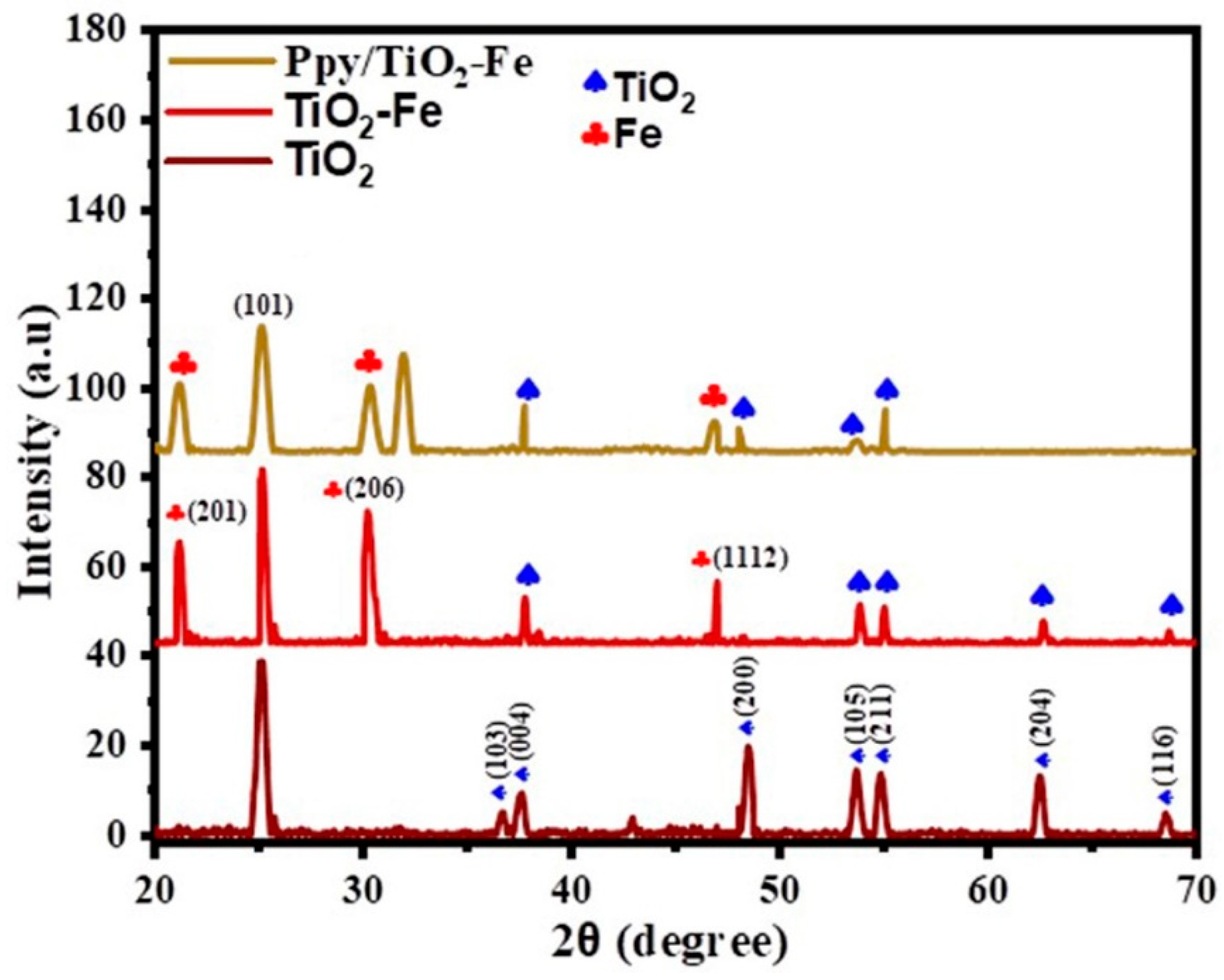
2.1. XRD Analysis

XRD provides information about the crystal structures of the catalyst components. It reveals the arrangement of atoms in the lattice, which can impact properties like mechanical strength, electrical conductivity, and catalytic activity. Understanding polypyrrole, TiO2, and iron crystal structures helps tailor their properties for specific applications.
The structural properties and phase composition of TiO2, TiO2-Fe, and Ppy/TiO2-Fe photocatalysts are demonstrated in Figure 2. The TiO2 pattern shows well-defined and intense peaks, suggesting that the material is well-crystallized and may be in the anatase or rutile phase. The 2θ values, along with diffraction planes of 25.08° (101), 36.64° (103), 37.53° (004), 48.45° (200), 53.65° (105), 54.81° (211), 62.44° (204), and 68.51° (116), XRD analysis revealed the tetragonal crystal structure of TiO2, confirmed by JCPDS card No. (01-084-1286) [25]. While Fe is introduced into the TiO2 phase, as evidenced in the TiO2-Fe pattern, the diffraction peaks are slightly shifted due to lattice distortions produced with Fe ions; the diffraction peaks near 21.13° (201), 30.2° (206), and 46.78° (1112) were observed, indicative of the presence of Fe and iron nitrate, as evidenced by (JCPDS card No. 00-015-0615). There are no significant changes in the pattern of Ppy/TiO2-Fe, which may be due to the low crystallinity of Ppy [28], and spectra are less resolved than the other samples, indicating the reduction in crystallinity and crystallite size. It seems that Ppy hinders the possibility of crystallization, thus resulting in relatively small and non-crystalline particles. These variations in crystallite size and peak broadening can be attributed to the influence of Fe doping and Ppy coating on the crystalline character of TiO2. In addition, the diffraction pattern of Ppy is not detected in the Ppy/TiO2-Fe photocatalyst, which could be attributed to an amorphous Ppy phase in the catalyst. From the result obtained here, it is clear that the presence of Ppy particles does not influence the crystal formation of the grown TiO2-Fe nanoparticles [26].
The Debye Equation (1) was employed to calculate crystallite size, revealing significant findings. The average crystallite size for yielding values of 24.99 nm for TiO2, 21.94 nm for TiO2–Fe, and 21.84 nm for Ppy/TiO2–Fe. As shown in Table 2, the crystallite size decreases with Fe doping and decreases slightly with the addition of Ppy, providing valuable insights into the properties of these catalysts.
D = k λ β cos θ
Our analysis, which includes the Debye Equation (1), comprehensively explains the crystallite size. The crystallite size of the prepared catalyst is given in Table 2, ensuring a thorough and reliable analysis.

2.2. Fourier Transform Infrared Spectroscopy (FTIR) Analysis

FTIR analysis is valuable for determining the composition of photocatalysts. The FTIR spectrum of TiO2, TiO2–Fe, and Ppy/TiO2–Fe photocatalysts are presented in Figure 3, showing a peak at 426 cm−1 corresponds to the Ti–O bond, which shifts to 534 cm−1 in TiO2–Fe, indicating the presence of the Fe–O bond [27]. Band positions at 1694 cm−1 and 3296 cm−1 in TiO2 and TiO2–Fe have been assigned to surface hydroxyl groups or adsorbed water; 3296 cm−1 is a combination of symmetric and asymmetric stretching frequencies of the hydroxyl group (Ti–OH) [29]. Further, at 2044 cm−1 assigned to C-H, stretching vibrations are due to residual organic species not being removed in ethanol and distilled water washing [30]. In Ppy/TiO2–Fe, the peak at 1058 cm−1 is attributed to the C-H deformation of polypyrrole (Ppy), while the 928 cm−1 peak indicates the doping state of Ppy, and the 730 cm−1 peak signifies polymerized pyrrole [28,31]. According to Li et al., there are also characteristic peaks of TiO2 within the 400–800 cm−1 range, which were not observed within Ppy/TiO2–Fe spectra, which confirmed that TiO2–Fe had been enveloped by Ppy [32]. Some shifts in peaks of Ppy/TiO2–Fe spectra were observed compared to TiO2 and TiO2–Fe spectra, which also confirmed the interaction between TiO2–Fe and Ppy [32]. Overall, Ppy/TiO2–Fe exhibits the most diverse spectrum with peaks from all identified groups, including polypyrrole-related ones. This analysis indicates the potential presence of surface hydroxyl groups or adsorbed water in Ppy/TiO2–Fe and TiO2–Fe, along with iron-related compounds, inspiring hope for their possible applications in various fields [33].

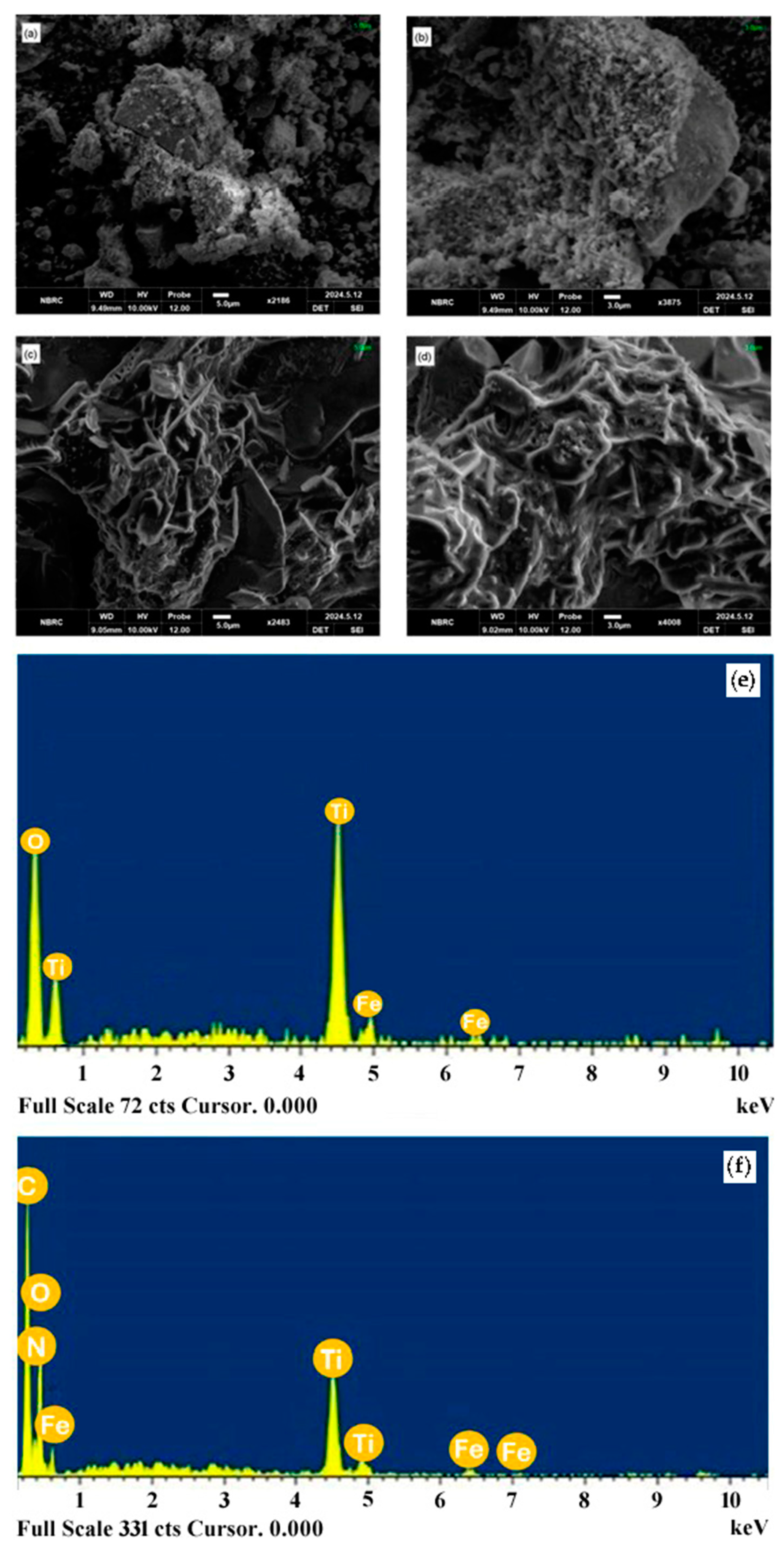
2.3. SEM and EDS Analysis

The collection of SEM images investigated the macro-morphology of the produced photocatalysts. The SEM images reveal the morphological properties of the TiO2–Fe and Ppy/TiO2–Fe samples at different resolutions, as shown in Figure 4a–d, revealing unique structural features. TiO2–Fe is shown in Figure 4a,b at low and high resolution, respectively. The sample appears to have an uneven, aggregated morphology with a range of particle sizes, as seen in the low-resolution image (Figure 4a). Particle clustering suggests the possibility of agglomeration. The surface of the particles appears rougher and has a more complex texture in the high-resolution image (Figure 4b). The higher resolution reveals finer structural details, like tiny sub-particles or surface pores [34].
Conversely, Ppy/TiO2–Fe is shown at low and high resolution in Figure 4c,d. Comparing TiO2–Fe to the low-resolution image (c), the structure is more complex and less agglomerated, and the network-like shape suggests the presence of polypyrrole. The intricate, fibrous structure of the polypyrrole is highlighted even more in the high-resolution image (d). In Figure 4 (e and f) EDS analysis was carried out to assess the purity and composition of TiO2–Fe and Ppy/TiO2–Fe samples. Fe, Ti, and O peaks were found in both graphs, and N and C peaks were present in the Ppy/TiO2–Fe sample. The presence of N and C peaks in Ppy/TiO2–Fe indicates the successful incorporation of Ppy into TiO2–Fe. It is worth mentioning that adding Ppy does not change the crystal structure, confirmed by the almost exact positioning of TiO2 and Fe in both graphs. This indicates better material qualities that may be advantageous for various applications, including sensing and catalysis [35].

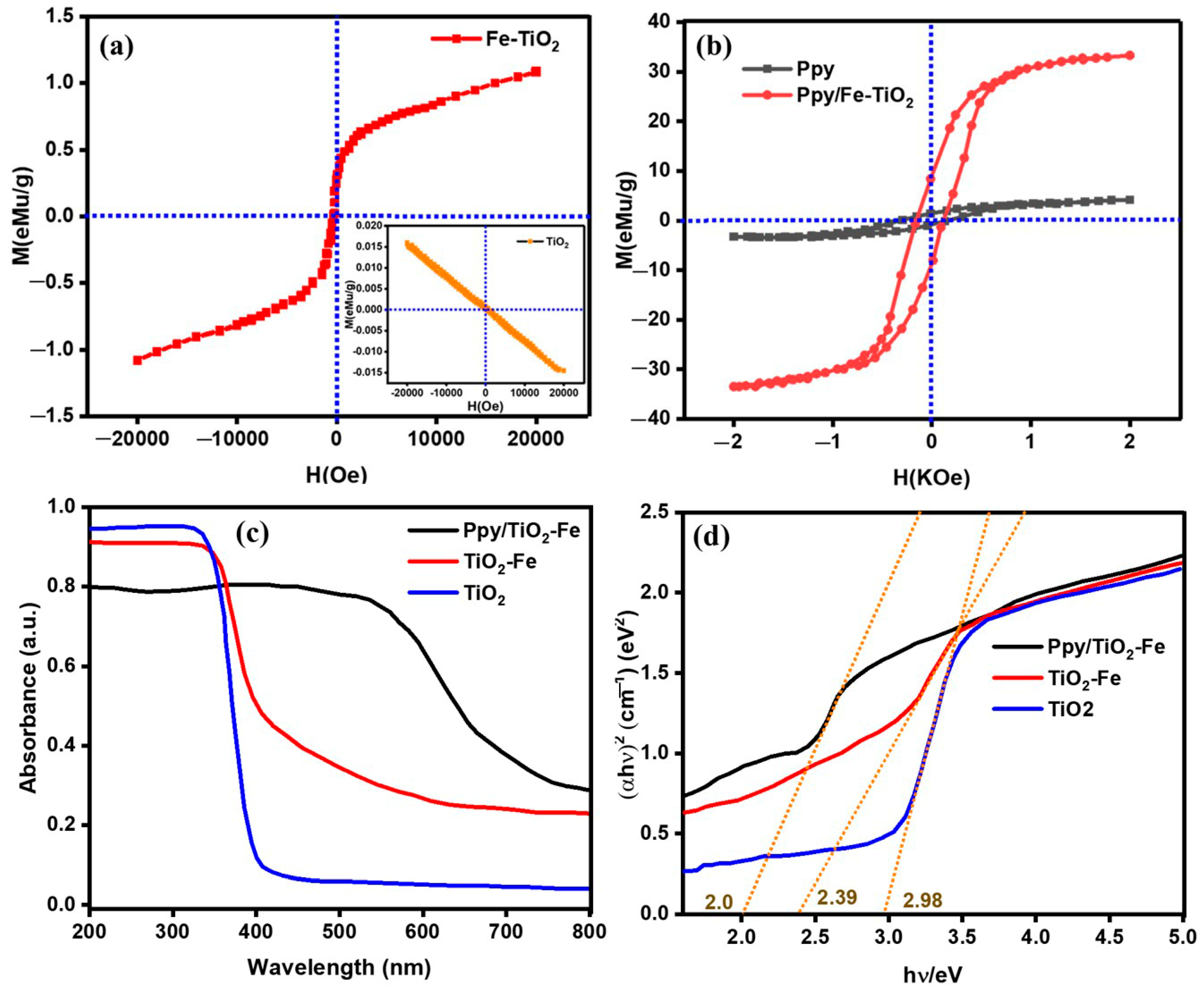
2.4. VSM and DRS Analysis

VSM can help quantify the relative amounts of each component in the prepared photocatalyst. This is useful for optimizing the catalyst’s composition for specific applications or ensuring the reproducibility of its properties. Figure 5 illustrates the magnetic properties of Fe–TiO2 and Ppy/Fe–TiO2 photocatalysts and how the properties vary as the samples’ composition changes. In the present study, the relaxations in Fe–TiO2 are genuinely ferromagnetic, which can be strongly inferred from the fact that the red curve in the M–H plot depicts an open hysteresis loop. In the case of Fe–TiO2, the coercivity (HC) is 341.39 Oe, the saturation magnetization (MS) of which is 1.09 emu/g and a remanence (Mr) of 0.29 emu/g, and as a result, obtaining an experimental magnetic moment of 0.0032 (μB). This ferromagnetism occurs due to Fe and TiO2 in the composite. The interaction between them is essential for any magnetic material [36]. The inset in the graph also points out that the pure phase of TiO2 has no magnetic property; its magnetization is close to zero. As for the magnetic susceptibility of Ppy and Ppy/TiO2–Fe, shown in Figure 5b, Ppy has very low or no magnetic properties, as evidenced by the small hysteresis loop in the grey curve [37]. But the photocatalyst Ppy/TiO2–Fe shows superparamagnetic properties owing to more considerable hysteresis and much higher saturation magnetization (MS) of 33.11 emu/g, with remanence (Mr) 8.39 emu/g and a coercivity (Hc) of 0.160 Oe and a significant value of the magnetic moment of 206.94 (μB) [38,39]. The presence of Ppy improves the magnetic properties of the catalytic system to a large extent. The results obtained from the M-H loop of Ppy/TiO2–Fe show a higher saturation magnetization, lower coercivity, and higher remanence than Fe-TiO2. This means that even after incorporating iron doping into TiO2 and applying polypyrrole (Ppy), it will retain the ferromagnetic nature of Fe–TiO2, making these composites ideal for magnetic devices. In both materials, the magnetic structure is multi-domain, and the nature hysteresis loops are non-square. It shows that the Fe, TiO2, and Ppy/TiO2–Fe photocatalysts significantly affect the magnetic properties, which is crucial for their potential applications in magnetic devices and sensors [32]. The comprehensive magnetic analysis of prepared catalysts is given in Table 3.
Photo-absorption plays a crucial role in determining the efficacy of photocatalysts. It is indicated in Figure 5d that the TiO2–Fe and TiO2 show absorption in the ultraviolet region (<400 nm). Due to the incorporation of Ppy, the Ppy/TiO2–Fe shows absorption in the visible-light region of 400–800 nm. The band gap energy analysis (Figure 5d) indicates that interaction between TiO2–Fe and Ppy significantly reduces the band gap energy from 2.39 to 2.0 eV. This modification could improve its photocatalytic performance when exposed to visible light [31].

2.5. N2 Adsorption-Desorption Analysis

The specific surface area of the composite material can be measured using N2 adsorption-desorption isotherms, typically through the Brunauer–Emmett–Teller (BET) method. A high surface area often indicates greater availability of active sites, which can enhance the composite’s performance in catalysis, sensing, or energy storage applications. N-containing functional groups and the p-conjugated structures of conductive PPy offer a high surface area that indicates greater availability of active sites, which can enhance the composite’s performance in catalysis, sensing, or energy storage applications [31].
BET plots in Figure 6 show that the superficial area and pore size give the required information about the mesoporous structure of the synthesized particles. The Ppy/TiO2–Fe photocatalyst underwent the N2 sorption analysis, which showed the type IV isotherm with a hysteresis loop of the H2 type (Figure 6), indicating that the sample had independent mesopores. The BET-specific surface area was 2.25 × 10² m2/g, which could be advantageous for the photocatalytic action of wastewater pollutants [38].

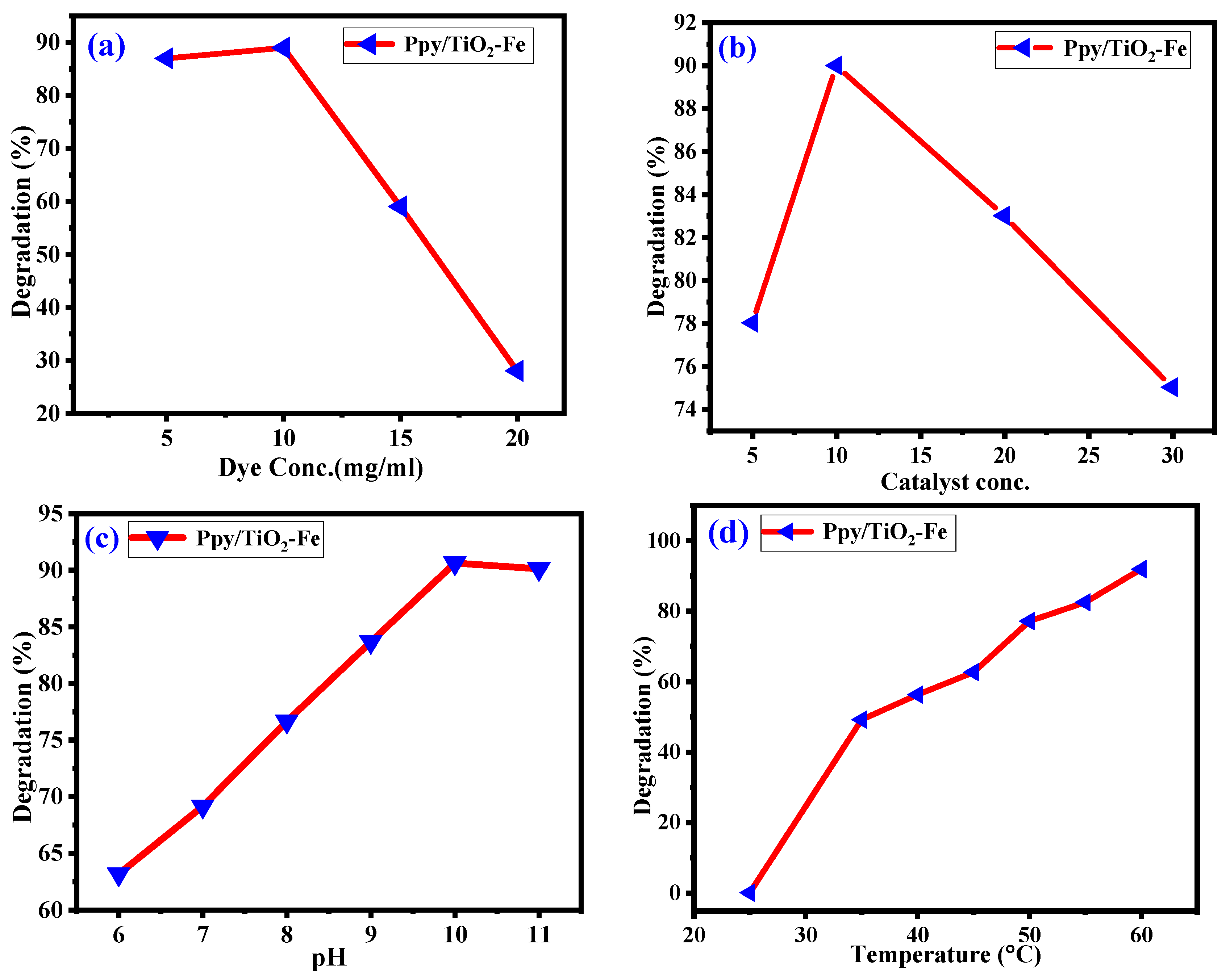
2.6. Parameters Factors Influencing Dye Degradation Rate

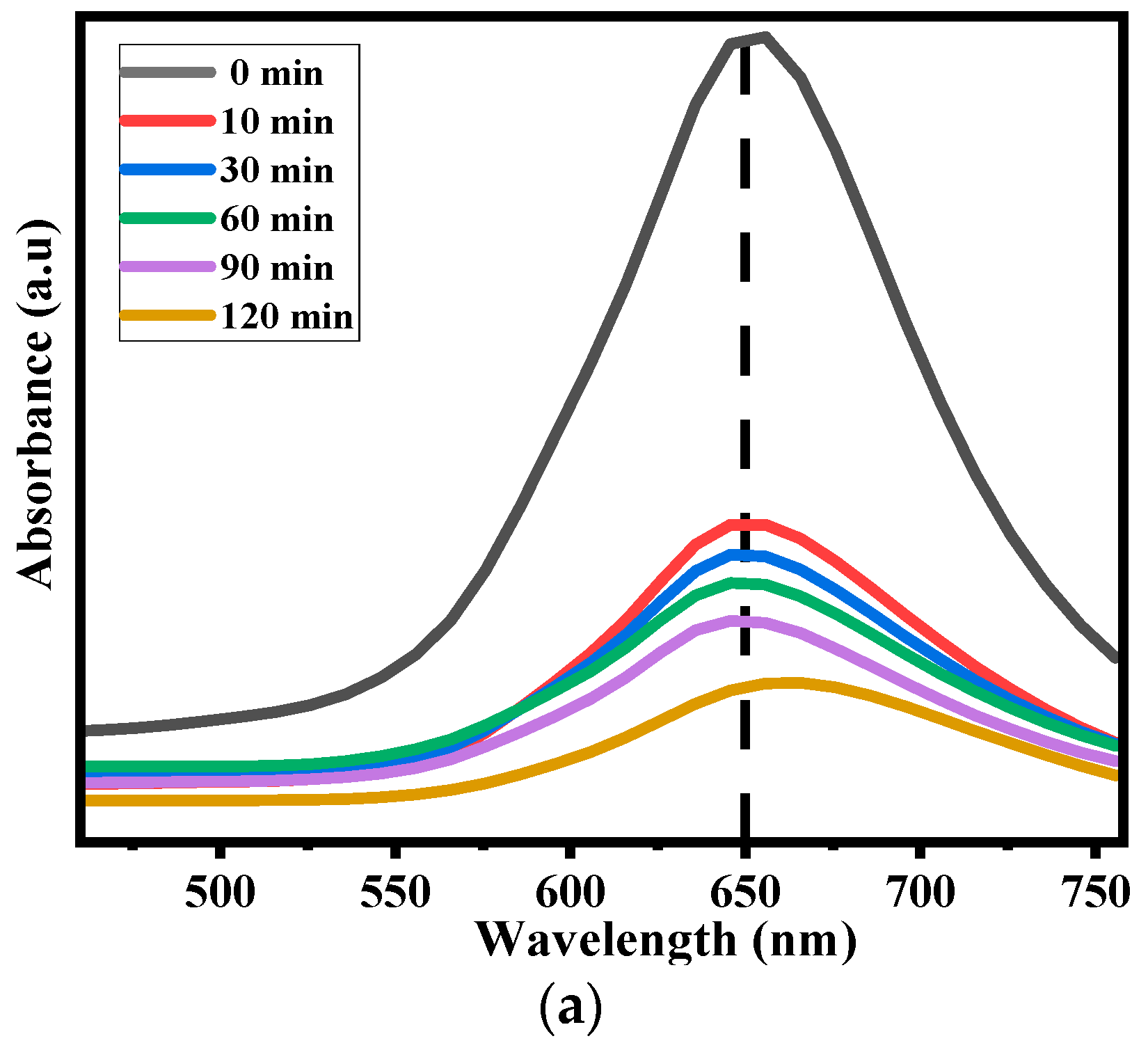
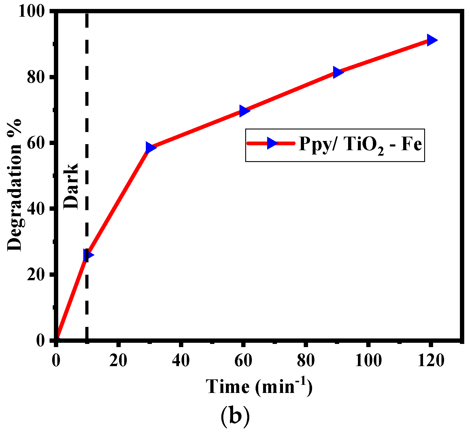
2.6.1. Effect of Contact Time

Figure 7 shows the photocatalytic degradation of Methylene Blue (MB) by the Ppy/TiO2–Fe photocatalyst under visible light. The absorption in the dark for 10 min was approximately 25.92%. Figure 7b highlights the degradation process of MB in the solution under sunlight irradiation using the synthesized Ppy/TiO2–Fe photocatalyst, where the detrimental effect of MB was observed to reduce with time as the photocatalytic reaction proceeded. As clearly illustrated in Figure 7a, the absorption of MB reduces significantly immediately after interacting with the Ppy/Fe–TiO2 photocatalyst under the 10 min visible light exposure, followed by a gradual decrease in the absorption peak intensities at 30-, 60-, and 90-min time intervals. Additionally, the photodegradation behavior recorded a slight decline in the absorption intensity, nearly 91% after 120 min. The Ppy/TiO2-Fe photocatalyst promotes 91.92% of incubation under visible light. These results are consistent with the calculated photodegradation rate/efficiency presented in Figure 7b.

2.6.2. Photocatalytic Efficiency of Ppy/Fe-TiO2

Figure 8a shows the initial dye concentrations’ effect on the degradation activity of Ppy/TiO2-Fe in MB dye degradation. First, when gradually raising the dye concentration from 5 to 10 mg/mL, the degradation efficiency does not drop much, staying at approximately 89%, which suggests that the photocatalyst is efficient for this range of dye concentration [40]. This implies that the catalyst has adequate, accessible active sites to carry out the degradation and adsorption processes of the MB dye, regardless of the concentration. The formation of a p-n heterojunction between Ppy and TiO2-Fe decreased the recombination of photogenerated charge carriers and enhanced the photocatalytic performance of the Ppy/TiO2–Fe [32]. However, as the dye concentration increases beyond 10 mg/mL, the degradation efficiencies reduce sharply to an optimum of approximately 40% at 20 mg/mL. Thus, a reduction in the quantity of dye adsorbed and degraded remained observed at advanced concentrations, likely due to the saturation of the active sites on the surface of the photocatalyst. Furthermore, raising conformity with the dye concentrates a solution and might affect light transmittance, thereby decreasing the photocatalytic generation of the reactive species with enhanced degradation ability. Graphically, the photocatalyst exhibits optimum photocatalytic activity at lower dye concentrations and gradually decreases at higher concentrations, indicating that the dye concentration is an essential factor to be controlled for optimum photocatalytic degradation. Figure 8b shows the comparative result of the photodegradation efficiency of MB dye in the presence of different doses of a Ppy/TiO2–Fe photocatalyst. With the increase in the catalyst dose from 5 mg to 10 mg, the degradation efficiency also increases; this may be due to the dispersion of the catalyst particles in the aqueous solution. This better dispersion offers a more enhanced surface that is exposed to the photons and, thus, increases the photocatalytic process. The graph achieves the maximum to fixed relational efficiency at 10 mg, hence a sign of optimality and the best dose of the catalyst for the degradation of the dye. Higher doses of the deliberately introduced catalyst, such as 15 and 20 mg, decrease the degradation efficiency. This reduction in the rate can be explained by the tendency of catalyst particles at higher cluster concentrations and, subsequently, a fundamental decrease in the area exposed to photons for their absorptions. Therefore, the MB dye is removed and enhanced until the optimal dose of the catalyst is reached. However, it decreases as the catalyst quantity increases to stress that an excellent photodegradation requires the optimal amount of the catalyst. Figure 8c shows the interaction of pH in the degradation rate of methylene blue (MB) dye employing a Ppy/TiO2–Fe photocatalyst. Thus, with an increase in the pH of the solution from 6 to 10, the level of degradation efficiency is observed up to 90.6% at pH 10. This trend also implied that photocatalytic activity is more favorably carried out in an alkaline environment. This has enhanced the efficiency of the process because there is an increased negative charge on the catalyst surface optimum pH for the removal of the dye, hence confirming the electrostatic attraction between the negatively charged catalyst and the positively charged MB dye molecules [41,42]. The other is a more vital interaction between the dye and the catalyst, so enhanced dye adsorption will reflect higher degradation rates. When the pH is increased to 11, one can observe a little decline in the efficiency, which might be due to the over-saturation of OH ions, which induces the recombination of electron-hole pairs in the photocatalyst. This recombination decreases the number of active sites for the opponent degradation reaction, so its performance drops somewhat. Therefore, the physicochemical properties of the photocatalyst can be identified: the optimum pH for the dye degradation process is around ten because, at this pH, the surface charge and the electrostatic attraction are at their highest [43,44]. Figure 8d reveals that degradation efficiency increases progressively with the temperature from 25 °C to 60 °C. It implies that the pollutant’s photocatalytic degradation happens using the developed Ppy/TiO2–Fe catalyst, which is best carried out under high temperatures. This improvement must be attributed to increased reaction kinetics where the temperature increases, thus increasing the probability of breaking down the pollutant. At around 60 °C, the degradation is 91.92%, indicating that the catalyst is most active at high temperatures [45]. The catalyst characterization experiments show that the catalyst almost loses its integrity at the highest temperature used in this study, implying that its performance is best at this temperature.

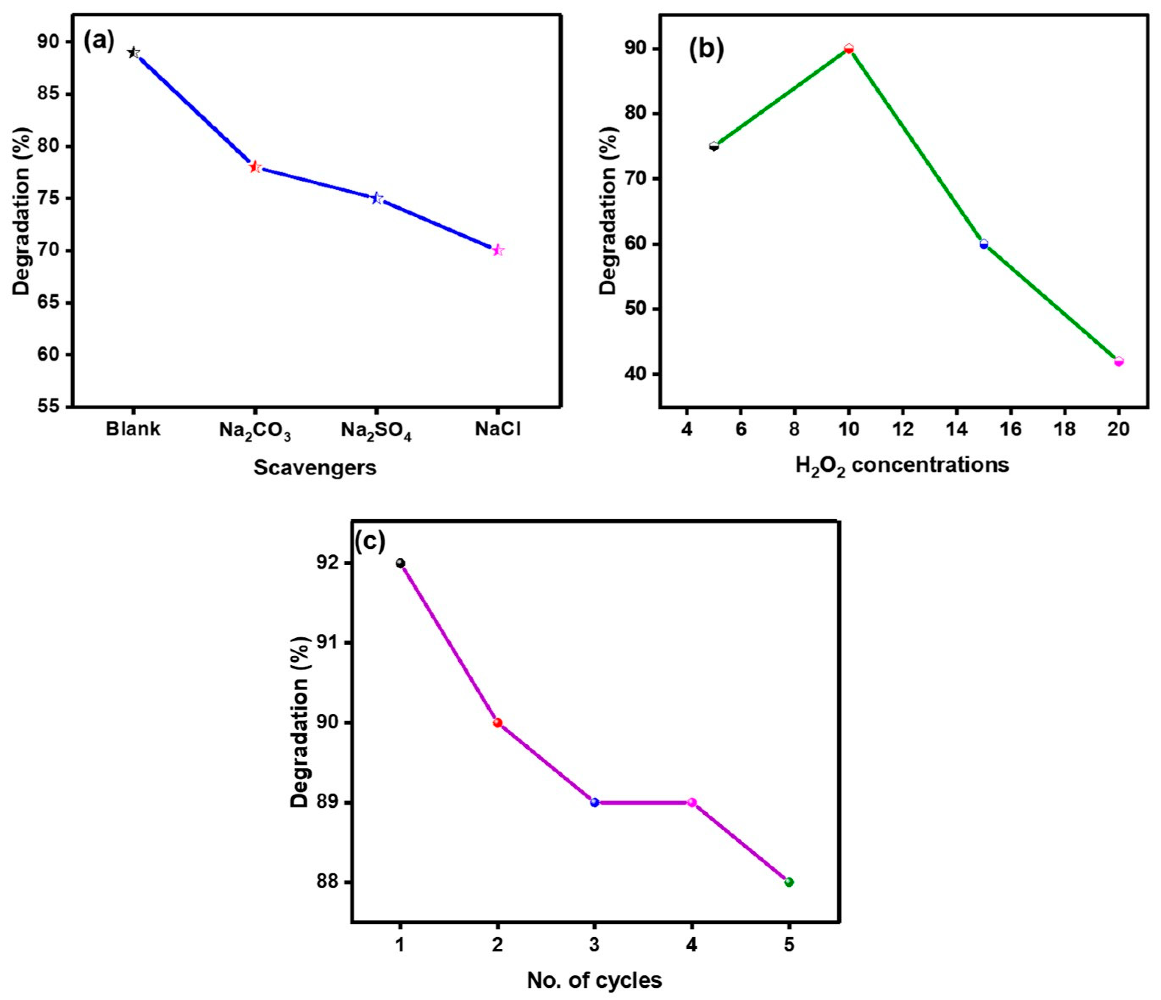
2.6.3. Scavengers Effect

The influence of scavengers was studied by adding sodium sulfate (Na2SO4), sodium chloride (NaCl), and sodium carbonate (Na2CO3) during the irradiation period of 120 min, as described in Figure 9a. The scavenging effect of radicals was found to be Cl > SO42− > CO32−. Bicarbonate ions react with hydroxyl radicals and produce carbonate radicals, which can scavenge holes. The photodegradation efficiency decreased with the sulfate ion due to its reaction with photogenerated holes, hydroxyl radicals, and adsorption on the catalyst’s surface [46]. NaCl had the highest inhibition rate of 70% because of the generation of OH radicals, which neutralize photo-generated holes. Numerical values of scavenging efficiencies (%): Na2SO4 (75%) and Na2CO3 (78%) also demonstrated the ability to scavenge hydroxyl ions and form carbonate radicals [47].

2.6.4. Impact of H2O2 Concentration

The influence of H2O2 concentration was investigated in the 5–20 mL range when another factor was fixed, as shown in Figure 9b. This proves that with an increase in the concentration of H2O2 from 5 to 10 mL, the degradation percentage increases; thus, at 10 mL, a high concentration of hydroxyl radical (˙OH) generated enhanced pollutant degradation. However, as the concentration reaches 10 mL and above, the degradation efficiency reduces because excess H2O2 reacts with the hydroxyl radicals to form less reactive species, thus lowering the overall degradation efficiency [48]. These hydroxyl radicals are highly recognized oxidants. They play a significant role in the photocatalytic degradation of MB dye, causing the dye to split into less toxic compounds.
H 2 O 2 + O 2 . OH . + O 2 + OH
H 2 O 2 + e CB OH . + OH
H 2 O 2 + hv 2 OH .

2.6.5. Recyclability of Ppy/Fe–TiO2 Photocatalyst

For real-life use, a photocatalyst should be chemically stable and reusable. From Figure 9c, it was observed that there was a slight decline in the efficiency of degradation of Ppy/Fe–TiO2 from 92% in the first cycle to 88% in the fourth cycle. Nevertheless, this minor decrease indicates its excellent catalytic performance, which has to do with good stability and crystalline structure. Some of the catalysts were observed to be lost during the recovery process, which slightly affected the efficiency of the photocatalyst. However, the fact that the Ppy/Fe–TiO2 exhibits outstanding reusability has fully testified to its feasibility in photocatalytic engineering. This work evaluates the life cycle assessments (LCA) of bionanocomposite to determine the extent of its effects on the environment and the nature of bionanocomposite as renewable, recyclable, and reusable. The nanocomposites have a better impact on supporting a nontoxic environment than the nanocomposites of the non-biodegradable base. Nanocomposites’ natural and nanoscale components hold no harm to the biosphere; they are degradable, biodegradable, and can be recycled or reused once their useful life span elapses [49].

2.7. Degradation Kinetics

With initial concentrations of 5 to 20 ppm, MB dye has been regarded as one of the most suitable dyes for assessing photocatalytic behavior under sunlight. First-order reaction equations were used to evaluate the degradation kinetics of MB dye, as depicted in Figure 10a [50,51]. The first-order reaction Equation (5) was applied to the reaction rate to study the reaction under sunlight exposure.
ln ( C C o ) = k t
C and Co are absorbances (initial and final) and rate constant ( k k). It should be noted that this is an actual rate law for the overall reaction where it has been integrated and thus written in the differential form. Therefore, using MB dye at different concentrations, the rate constant was determined from the graph between ln C/Co and time. As the original concentration of MB rises, the slopes of the lines increase, implying a faster degradation rate. It is also possible to identify that 10 ppm concentration is the most effective, as it simultaneously furnishes the highest degradation rate with linearity characteristics. This is validated by the linear regression analysis that shows R2 that ranges between 0.83, 0.99, 0.97, and 0.96 for the initial concentrations of 5 to 20 ppm in that order. Also, the reaction’s rate constant (k) was obtained to measure how fast the reaction was proceeding. As seen in Table 4, the chosen 10 ppm concentration also generates a high R2 value while, at the same time, presenting a more significant rate constant value, suggesting that the prepared catalyst and visible light illumination are efficient at the chosen concentration. Therefore, based on the conditions of this study, the 10 ppm concentration of MB gives the best overall degradation efficiency and model fit.
The Langmuir–Hinshelwood (L-H) model (Figure 10b) was applied using the following equation:
1 K obs = 1 K C K L H + C o / K C
In this equation, Kc represents the surface reaction rate constant in mgL−1 min−1, K is the first-order reaction rate constant, Co is the initial dye concentration in mg/L, and KL−H is the adsorption equilibrium constant in L/mg. This yielded an L−H plot of 1/Kobs against Co. The results suggest that the photocatalytic degradation of MB dye was followed by first-order model kinetics [52]. Table 4 presents the rate constant values for the pseudo-first-order model with varying initial concentrations of MB dye.

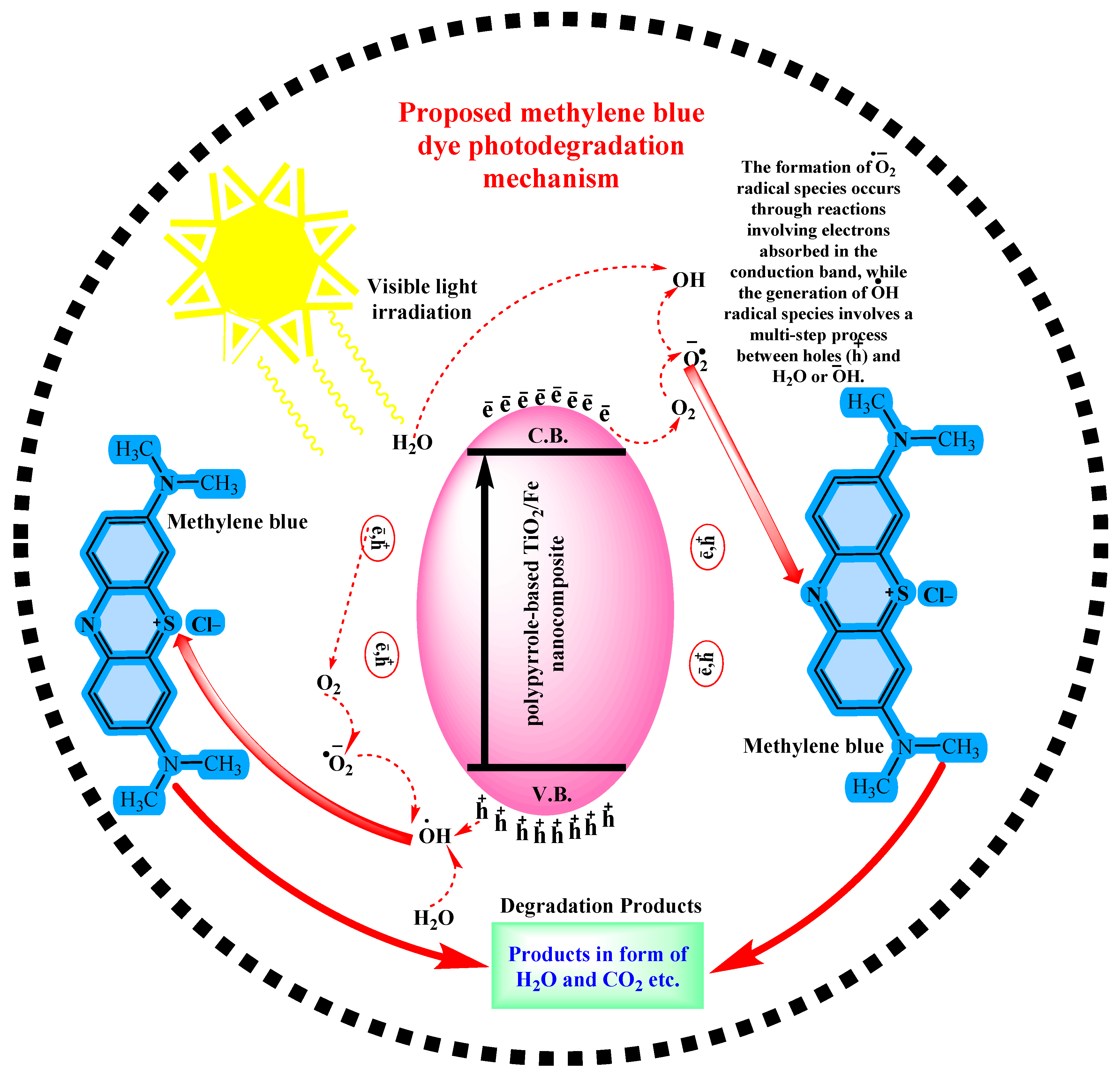
2.8. Mechanism of Photocatalytic Activity

Upon light absorption, the photocatalyst experiences the excitation of electrons from the valence band to the conduction band, forming electron-hole pairs. These reactive species interact with water and oxygen molecules, producing hydroxyl and superoxide radicals. Hydroxyl radicals, in particular, are potent oxidants capable of mineralizing organic compounds into more straightforward, less harmful substances. The specific photocatalyst used, in this case, a Ppy/TiO2–Fe photocatalyst, influences the efficiency of electron-hole pair generation and subsequent radical formation, ultimately determining the rate of pollutant degradation [53,54]. The following is a general mechanism (as illustrated in Figure 11) of photocatalytic degradation of dye [42].
Ppy / TiO 2 Fe   + UV   light   ( 650   nm ) Ppy / TiO 2 Fe   ( e cb +   h vb + ) Ppy / TiO 2 Fe   ( h vb + ) + H 2 O Ppy / TiO 2 Fe   + H + + · OH Ppy / TiO 2 Fe   ( h vb + ) +   OH Ppy / TiO 2 Fe   + · OH Ppy / TiO 2 Fe   ( e cb ) + O 2 Ppy / TiO 2 Fe + O 2 O 2 + H + HO 2 HO 2 + HO 2 H 2 O 2 +   O 2 H 2 O 2 + O 2 OH   + OH + O 2 Dye   + OH Degradation   products

3. Experimental Section

3.1. Materials

Titanium chloride hexahydrate (TiCl4•6H2O, 99.9%), ammonium chloride (NH4Cl, Sigma-Aldrich, 99.9%), ethanol (99.9%), iron(II) chloride dihydrate (FeCl2•2H2O, 99.9%), hydrochloric acid (HCl, 35% v/v), titanium(IV) n-butoxide (Ti(n-OBu)4, 98%), pyrrole (98%), ammonium persulfate (APS, 98%), and methanol (99.9%) from Sigma Aldrich Taufkirchen, Germany, distilled or de-ionized water from Aquafina, a division of PepsiCo Beverages North America (PBNA).

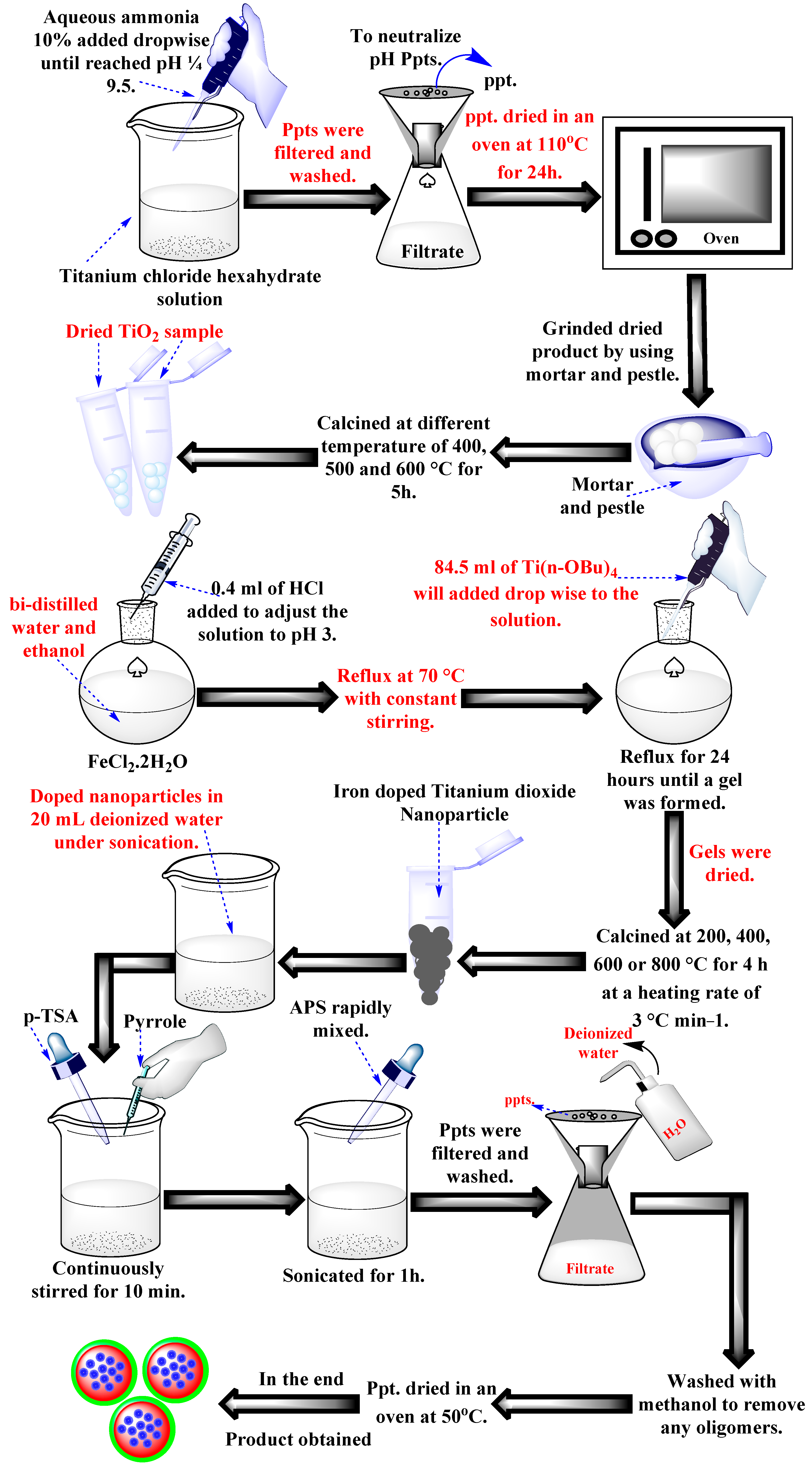
3.2. Synthesis of Titanium Dioxide Nanoparticles

Deionized water was used as the solvent in a low-temperature co-precipitation method to create titanium dioxide (TiO2). A solution of titanium chloride hexahydrate (0.5 mol, 54.9 mL) diluted in deionized water was mixed with 10% aqueous ammonia (10 mL) dropwise until the pH reached 9.5. The final product was filtered to separate it, then repeatedly cleaned with a 2% NH4Cl solution and hot distilled water until it was ion-free. The Ti(OH)2 precipitate was dried for a whole day at 110 °C. TiO2 was produced by heat treatment for five hours at different calcination temperatures of 400, 500, and 600 °C. The dried TiO2 samples were also sieved using a 200 μm filter to get tiny, homogeneous particles.

3.3. Synthesis of Iron-Doped Titanium Dioxide Nanoparticles

The following method was used to create iron-doped titanium dioxide nanoparticles (TiO2–Fe, 1%, pH 3) with 1.0 weight percent iron: To get the pH of the solution to 3, 15.0 mL of bi-distilled water, 50.0 mL of ethanol, 0.045 g of FeCl2·2H2O (Baker, 99.9%), and 0.4 mL of HCl (Baker, 35% v/v) were combined. At 70 °C, the solution was allowed to reflux while being continuously stirred. Ti(n-OBu)4 (Strem Chemicals, 98%) was then added to the solution dropwise in an amount of 84.5 mL. The resultant sol was kept under reflux at 70 °C for 24 h or until a gel started to form. The gels were then dried and calcined for four hours at a 3 °C/min heating rate at 200, 400, 600, or 800 °C.

3.4. Synthesis of Polypyrrole-Based Iron-Doped Titanium Dioxide Photocatalyst

The corresponding volumes of synthesized doped nanoparticles (TiO2–Fe) were dissolved by sonication in 20 mL of deionized water to create a dispersion medium. A round-bottom flask containing p-Toluenesulfonic acid (p-TSA) (6.0 mmol) and pyrrole (7.3 mmol) was filled with 15 mL of the nanoparticle-suspended solution, continuously sonicated for 10 min. After adding the reagent ammonium persulfate (APS) (3.6 mmol) to the solution at room temperature, the mixture was subjected to an hour-long ultrasonic treatment. Additionally, employing sonication for seven minutes—a technique previously employed in a study on iron oxide particles the size of microns—investigated the effect of reaction time.
Both mechanical and ultrasonic stirring techniques were used, and the manner used determined the characteristics of the resulting nanocomposite. After every product’s synthesis, deionized water was used to remove any leftover APS and p-TSA, and methanol was added to remove any oligomers that could have developed. The precipitated powder was dried at 50 °C following analysis to ensure powder purity. Figure 12 provides a schematic depiction of the photocatalysts’ production.

3.5. Structural Characterization

FTIR study remained to recognize the functional groups existing on synthesized TiO2, TiO2-Fe, and Ppy/TiO2–Fe photocatalysts. The analysis was conducted on a Perkin Elmer FTIR (Waltham, MS, USA)spectrometer based on the 400–4000 cm−1 spectra. XRD patterns of synthesized samples were carried out with the help of JEOL XRD. The research laboratory uses XRD with indigenous JDX-3532 apparatus and Mn-filtered Cu–Kα radiations. The morphology was analyzed using the JSM IT-100 JEOL, made in Japan, a scanning electron micrographic machine. Samples’ magnetic characterization of different was done using the Magnetometer Model 155 at 300 K. To evaluate the surface area and porosity of the developed materials, CO2 adsorption isotherms will be utilized. The measurements will be conducted at 273 K, and the volumetric adsorption analyzer will be used. The obtained isotherm data will be regressively analyzed using BET to obtain data on the samples’ specific surface area, pore volume, and pore size.

3.6. Photocatalytic Degradation of MB Dye

The photocatalytic performance of all synthesized samples was evaluated under visible light exposure. To explore the catalyst’s potential for degrading a water-soluble dye like methylene blue (MB) under visible light illumination (halogen lamp, 400 W, metal halide, λ ≥ 400 nm with λmax = 546 nm, UV cut filter coating) The light intensity (∼170 W/m2) was measured by “EXTECH Instrument(Nashua, NH, USA), Model 401027, Luximetro de Bolsillo” at a distance of 15 cm between the lamp and sample. A reaction mixture was prepared by adding 500 mg of the catalyst to 500 mL of MB solution. Before the photocatalytic experiment, the suspension containing MB and the Ppy/TiO2-Fe catalyst was stirred in the dark until equilibrium between the dye molecules and the catalyst surface was reached. Additionally, when exposed to visible light, the aqueous suspension did not change color without the catalyst. Therefore, effective degradation requires the combination of irradiation and the presence of the Ppy/TiO2–Fe catalyst. The suspension samples were removed at specific intervals, centrifuged, and filtered. Finally, at 650 nm, every sample’s concentration of MB was detected using the UV–visible spectrophotometer. This photocatalytic performance of the catalyst particles is determined by the extent of decolorization of MB in water. The following equation determined the dye decolorization level:
%   Degradation   efficiency   = A o A t A o × 100
where Ao is the initial absorbance of the dye solution. At is the absorbance of the dye solution at a given time (T).

3.7. Parameters Affecting the Rate of Dye Degradation

The outcome of many factors on dye degradation using Ppy/TiO2-Fe photocatalyst was studied to understand how the reaction proceeded. Firstly, the pH of the reaction was regulated on one of the scales within the range of 1 to 11 using NaOH and HCl. In this arrangement, 50 mL of 10 ppm of MB dye was mixed with 30 mg of Ppy/TiO2-Fe photocatalyst; the decrease in absorbance over time evaluated the percent decolorization. Contact time was also considered by adding a given amount of dye solution to the Ppy/TiO2-Fe photocatalyst at the optimal pH and varying it from 10 to 80 min. The required percentage of dye degradation was calculated to decide the further time for experimentation. Furthermore, the impact that was attributed to adsorbent dosage was studied by regulating the amount of catalyst through the range of 0.00 to 0.1 mg when 50 mL of 10 ppm MB dye is used and find out the % age MB dye degradation at the contact time of optimum. Moreover, the effect of dye concentration was investigated by exposing the 50 mL of dye solutions at a concentration of between 5 and 25 ppm with a fixed quantity of Ppy/TiO2-Fe photocatalyst, and the degradation percentage was determined at the optimal contact period only. More so, to assess the impact of temperature in the degradation of the dye, the reactions were carried out in different temperature ranges of 25–60 °C with an optimal amount of Ppy/TiO2-Fe photocatalyst to 50 mL of 10 ppm MB dye, and the efficiency was determined by the percentage dye degradation after the optimal time for the preceding conditions.

4. Conclusions

In this study, a Ppy/TiO2–Fe photocatalyst was successfully synthesized and characterized for its potential use in the photocatalytic breakdown of MB dye. The incorporation of Fe into TiO2 led to a decrease in crystallite size. Ppy/TiO2–Fe photocatalyst has a superparamagnetic character, and enhancement of Ms is found to be 33.11 emu/g and Hc of 0.160 Oe, due to which it is better suitable for magnetic devices as compared to TiO2–Fe having Ms of 1.09 emu/g and Hc of 341.39 Oe, as confirmed by XRD and VSM analyses. Adding polypyrrole further enhanced the photocatalyst’s structural and surface characteristics, as evidenced by SEM and FTIR analyses. The photocatalytic experiments demonstrated that the Ppy/TiO2–Fe photocatalyst exhibited a high degradation efficiency of 91.92% for methylene blue under optimal conditions, with the degradation process influenced by factors like concentration of dye, catalyst dosage, and pH. The study highlights the potential of Ppy/TiO2–Fe as an efficient and environmentally friendly photocatalyst for wastewater treatment applications. Future work could focus on scaling up the synthesis process and exploring the material’s performance with other organic pollutants in natural wastewater systems.

Author Contributions

Methodology, M.K.N., M.B.T. and S.J.; Software, H.A., D.F.B. and A.A.; Formal analysis, R.H.A. and O.M.A.; Investigation, M.M.A.; Resources, M.M.A.; Data curation, M.M.A.; Writing—original draft, M.K.N. and S.J.; Writing—review and editing, M.B.T., M.I.K., A.S. and J.F.-G.; Visualization, M.M.A., O.M.A. and M.I.K.; Supervision, M.M.A. and M.B.T.; Project administration, M.B.T. All authors have read and agreed to the published version of the manuscript.

Funding

This research was funded by Taif University, Saudi Arabia, project number (TU-DSPP-2024-276).

Data Availability Statement

All data are present within the manuscript body.

Acknowledgments

The authors extend their appreciation to the Higher Education Commission. Pakistan, Fundação para a Ciência e Tecnologia and Ministério da Ciência, Tecnologia e Ensino Superior (project DOIs: 10.54499/LA/P/0008/2020, 10.54499/UIDP/50006/2020, 10.54499/UIDB/50006/2020 and Scientific Employment Stimulus—Institutional Call DOI 10.54499/CEECINST/00102/2018/CP1567/CT0026) and IQS-School of Engineering and GESPA group are recognized as Consolidated Research Group by the Catalan Government (2021 SGR 00321). They also acknowledge funding from the project HEC-A20.1267.

Conflicts of Interest

Authors declare no conflicts of interest.

References

  1. Das, A.; Dey, A. P-Nitrophenol-Bioremediation using potent Pseudomonas strain from the textile dye industry effluent. J. Environ. Chem. Eng. 2020, 8, 103830. [Google Scholar] [CrossRef]
  2. Lakshmi, S.; Suvedha, K.; Sruthi, R.; Lavanya, J.; Varjani, S.; Nakkeeran, E. Hexavalent chromium sequestration from electronic waste by biomass of Aspergillus carbonarius. Bioengineered 2020, 11, 708–717. [Google Scholar] [CrossRef] [PubMed]
  3. Shindhal, T.; Rakholiya, P.; Varjani, S.; Pandey, A.; Ngo, H.H.; Guo, W.; Ng, H.Y.; Taherzadeh, M.J. A critical review on advances in the practices and perspectives for the treatment of dye industry wastewater. Bioengineered 2021, 12, 70–87. [Google Scholar] [CrossRef] [PubMed]
  4. Javaid, R.; Qazi, U.Y. Catalytic oxidation process for the degradation of synthetic dyes: An overview. Int. J. Environ. Res. Public Health 2019, 16, 2066. [Google Scholar] [CrossRef] [PubMed]
  5. Bilal, M.; Iqbal, M.; Hu, H.; Zhang, X. Mutagenicity and cytotoxicity assessment of biodegraded textile effluent by Ca-alginate encapsulated manganese peroxidase. Biochem. Eng. J. 2016, 109, 153–161. [Google Scholar] [CrossRef]
  6. Varjani, S.; Rakholiya, P.; Ng, H.Y.; You, S.; Teixeira, J.A. Microbial degradation of dyes: An overview. Bioresour. Technol. 2020, 314, 123728. [Google Scholar] [CrossRef]
  7. Adeyemo, A.A.; Adeoye, I.O.; Bello, O.S. Adsorption of dyes using different types of clay: A review. Appl. Water Sci. 2017, 7, 543–568. [Google Scholar] [CrossRef]
  8. Tichapondwa, S.M.; Newman, J.; Kubheka, O. Effect of TiO2 phase on the photocatalytic degradation of methylene blue dye. Phys. Chem. Earth Parts A/B/C 2020, 118, 102900. [Google Scholar] [CrossRef]
  9. Rajoriya, S.; Bargole, S.; Saharan, V.K. Degradation of reactive blue 13 using hydrodynamic cavitation: Effect of geometrical parameters and different oxidizing additives. Ultrason. Sonochem. 2017, 37, 192–202. [Google Scholar] [CrossRef]
  10. Chen, C.; Ma, W.; Zhao, J. Semiconductor-mediated photodegradation of pollutants under visible-light irradiation. Chem. Soc. Rev. 2010, 39, 4206–4219. [Google Scholar] [CrossRef]
  11. Chopra, L. Photocatalytic activity of zinc oxide for dye and drug degradation: A review. Mater. Today Proc. 2022, 52, 1653–1656. [Google Scholar]
  12. Ahmed, M.; El-Katori, E.E.; Gharni, Z.H. Photocatalytic degradation of methylene blue dye using Fe2O3/TiO2 nanoparticles prepared by sol–gel method. J. Alloys Compd. 2013, 553, 19–29. [Google Scholar] [CrossRef]
  13. Kazemi, M.; Mohammadizadeh, M. Simultaneous improvement of photocatalytic and superhydrophilicity properties of nano TiO2 thin films. Chem. Eng. Res. Des. 2012, 90, 1473–1479. [Google Scholar] [CrossRef]
  14. Saha, S.; Wang, J.; Pal, A. Nano silver impregnation on commercial TiO2 and a comparative photocatalytic account to degrade malachite green. Sep. Purif. Technol. 2012, 89, 147–159. [Google Scholar] [CrossRef]
  15. Zhao, W.; Bai, Z.; Ren, A.; Guo, B.; Wu, C. Sunlight photocatalytic activity of CdS modified TiO2 loaded on activated carbon fibers. Appl. Surf. Sci. 2010, 256, 3493–3498. [Google Scholar] [CrossRef]
  16. Puma, G.L.; Bono, A.; Krishnaiah, D.; Collin, J.G. Preparation of titanium dioxide photocatalyst loaded onto activated carbon support using chemical vapor deposition: A review paper. J. Hazard. Mater. 2008, 157, 209–219. [Google Scholar] [CrossRef]
  17. Wang, T.; Zhu, Y.-C.; Sun, Z.-X.; Wu, L.-G. Preparation of weak light driven TiO2 multi composite photocatalysts via adsorption phase synthesis. Huan Jing Ke Xue = Huanjing Kexue 2015, 36, 559–567. [Google Scholar]
  18. Chen, M.-N.; Mo, L.-P.; Cui, Z.-S.; Zhang, Z.-H. Magnetic nanocatalysts: Synthesis and application in multicomponent reactions. Curr. Opin. Green Sustain. Chem. 2019, 15, 27–37. [Google Scholar] [CrossRef]
  19. Suliman, Z.A.; Mecha, A.C.; Mwasiagi, J.I. Effect of TiO2/Fe2O3 nanopowder synthesis method on visible light photocatalytic degradation of reactive blue dye. Heliyon 2024, 10, e29648. [Google Scholar] [CrossRef]
  20. Deng, Q.; Shen, Y.; Zhu, H.; Tu, T. A magnetic nanoparticle-supported N-heterocyclic carbene-palladacycle: An efficient and recyclable solid molecular catalyst for Suzuki–Miyaura cross-coupling of 9-chloroacridine. Chem. Commun. 2017, 53, 13063–13066. [Google Scholar] [CrossRef]
  21. Xu, L.; Zhang, S.Z.; Li, W.; Zhang, Z.H. Visible-Light-Mediated Oxidative Amidation of Aldehydes by Using Magnetic CdS Quantum Dots as a Photocatalyst. Chem.—Eur. J. 2021, 27, 5483–5491. [Google Scholar] [CrossRef] [PubMed]
  22. Rakibuddin, M.; Ananthakrishnan, R. Novel nano coordination polymer based synthesis of porous ZnO hexagonal nanodisk for higher gas sorption and photocatalytic activities. Appl. Surf. Sci. 2016, 362, 265–273. [Google Scholar] [CrossRef]
  23. Kumar, R.; El-Shishtawy, R.M.; Barakat, M.A. Synthesis and characterization of Ag-Ag2O/TiO2@ polypyrrole heterojunction for enhanced photocatalytic degradation of methylene blue. Catalysts 2016, 6, 76. [Google Scholar] [CrossRef]
  24. Lin, C.-C.; Ho, J.-M. Structural analysis and catalytic activity of Fe3O4 nanoparticles prepared by a facile co-precipitation method in a rotating packed bed. Ceram. Int. 2014, 40, 10275–10282. [Google Scholar] [CrossRef]
  25. Khan, S.; Noor, A.; Khan, I.; Muhammad, M.; Sadiq, M.; Muhammad, N. Photocatalytic degradation of organic dyes contaminated aqueous solution using binary CdTiO2 and ternary NiCdTiO2 nanocomposites. Catalysts 2022, 13, 44. [Google Scholar] [CrossRef]
  26. Moalej, N.S.; Ahadi, S.; Sheibani, S. Photocatalytic degradation of methylene blue by 2 wt.% Fe doped TiO2 nanopowder under visible light irradiation. J. Ultrafine Grained Nanostruct. Mater. 2019, 52, 133–141. [Google Scholar]
  27. Li, R.; Jia, Y.; Bu, N.; Wu, J.; Zhen, Q. Photocatalytic degradation of methyl blue using Fe2O3/TiO2 composite ceramics. J. Alloys Compd. 2015, 643, 88–93. [Google Scholar] [CrossRef]
  28. Feng, J.; Sun, N.; Wu, D.; Yang, H.; Xu, H.; Yan, W. Preparation of Fe3O4/TiO2/polypyrrole ternary magnetic composite and using as adsorbent for the removal of acid red G. J. Polym. Environ. 2017, 25, 781–791. [Google Scholar] [CrossRef]
  29. Ali, H.; Ismail, A. Fabrication of magnetic Fe3O4/Polypyrrole/carbon black nanocomposite for effective uptake of congo red and methylene blue dye: Adsorption investigation and mechanism. J. Polym. Environ. 2023, 31, 976–998. [Google Scholar] [CrossRef]
  30. Sood, S.; Umar, A.; Mehta, S.K.; Kansal, S.K. Highly effective Fe-doped TiO2 nanoparticles photocatalysts for visible-light driven photocatalytic degradation of toxic organic compounds. J. Colloid Interface Sci. 2015, 450, 213–223. [Google Scholar] [CrossRef]
  31. Kumar, M.A.; Abebe, B.; Nagaswarupa, H.; Murthy, H.A.; Ravikumar, C.; Sabir, F.K. Enhanced photocatalytic and electrochemical performance of TiO2-Fe2O3 nanocomposite: Its applications in dye decolorization and as supercapacitors. Sci. Rep. 2020, 10, 1249. [Google Scholar] [CrossRef] [PubMed]
  32. Yuan, X.; Kobylanski, M.P.; Cui, Z.; Li, J.; Beaunier, P.; Dragoe, D.; Colbeau-Justin, C.; Zaleska-Medynska, A.; Remita, H. Highly active composite TiO2-polypyrrole nanostructures for water and air depollution under visible light irradiation. J. Environ. Chem. Eng. 2020, 8, 104178. [Google Scholar] [CrossRef]
  33. Wei, J.; Zhao, L.; Peng, S.; Shi, J.; Liu, Z.; Wen, W. Wettability of urea-doped TiO2 nanoparticles and their high electrorheological effects. J. Sol-Gel Sci. Technol. 2008, 47, 311–315. [Google Scholar] [CrossRef]
  34. Wang, D.; Wang, Y.; Li, X.; Luo, Q.; An, J.; Yue, J. Sunlight photocatalytic activity of polypyrrole–TiO2 nanocomposites prepared by ‘in situ’method. Catal. Commun. 2008, 9, 1162–1166. [Google Scholar] [CrossRef]
  35. Deng, F.; Li, Y.; Luo, X.; Yang, L.; Tu, X. Preparation of conductive polypyrrole/TiO2 nanocomposite via surface molecular imprinting technique and its photocatalytic activity under simulated solar light irradiation. Colloids Surf. A Physicochem. Eng. Asp. 2012, 395, 183–189. [Google Scholar] [CrossRef]
  36. Guo, G.-S.; He, C.-N.; Wang, Z.-H.; Gu, F.-B.; Han, D.-M. Synthesis of titania and titanate nanomaterials and their application in environmental analytical chemistry. Talanta 2007, 72, 1687–1692. [Google Scholar] [CrossRef]
  37. Arora, K.; Chaubey, A.; Singhal, R.; Singh, R.P.; Pandey, M.; Samanta, S.; Malhotra, B.; Chand, S. Application of electrochemically prepared polypyrrole–polyvinyl sulphonate films to DNA biosensor. Biosens. Bioelectron. 2006, 21, 1777–1783. [Google Scholar] [CrossRef]
  38. Roy, S.; Mishra, S.; Yogi, P.; Saxena, S.K.; Sagdeo, P.R.; Kumar, R. Synthesis of conducting polypyrrole-titanium oxide nanocomposite: Study of structural, optical and electrical properties. J. Inorg. Organomet. Polym. Mater. 2017, 27, 257–263. [Google Scholar] [CrossRef]
  39. Li, Q.; Zhang, C.; Li, J. Photocatalytic and microwave absorbing properties of polypyrrole/Fe-doped TiO2 composite by in situ polymerization method. J. Alloys Compd. 2011, 509, 1953–1957. [Google Scholar] [CrossRef]
  40. Rouhi, M.; Babamoradi, M.; Hajizadeh, Z.; Maleki, A.; Maleki, S.T. Design and performance of polypyrrole/halloysite nanotubes/Fe3O4/Ag/Co nanocomposite for photocatalytic degradation of methylene blue under visible light irradiation. Optik 2020, 212, 164721. [Google Scholar] [CrossRef]
  41. Choudhury, B.; Verma, R.; Choudhury, A. Oxygen defect assisted paramagnetic to ferromagnetic conversion in Fe doped TiO2 nanoparticles. RSC Adv. 2014, 4, 29314–29323. [Google Scholar] [CrossRef]
  42. Han, K.-H.; Kim, Y.-H.; Mun, M.-H.; Yu, J.-H.; Han, R.-H. Synthesis of polypyrrole-modified Fe3O4/SiO2/TiO2 nanocomposite microspheres and their photocatalytic activity. Mater. Res. Express 2022, 9, 025007. [Google Scholar] [CrossRef]
  43. Li, K.; Liu, S.; Xue, Y.; Zhang, L.; Han, Y. A superparamagnetic Fe3O4–TiO2 composite coating on titanium by micro-arc oxidation for percutaneous implants. J. Mater. Chem. B 2019, 7, 5265–5276. [Google Scholar] [CrossRef]
  44. Wuang, S.C.; Neoh, K.G.; Kang, E.-T.; Pack, D.W.; Leckband, D.E. Synthesis and functionalization of polypyrrole-Fe3O4 nanoparticles for applications in biomedicine. J. Mater. Chem. 2007, 17, 3354–3362. [Google Scholar] [CrossRef]
  45. Park, D.E.; Chae, H.S.; Choi, H.J.; Maity, A. Magnetite–polypyrrole core–shell structured microspheres and their dual stimuli-response under electric and magnetic fields. J. Mater. Chem. C 2015, 3, 3150–3158. [Google Scholar] [CrossRef]
  46. Hassani, A.; Khataee, A.; Karaca, S. Photocatalytic degradation of ciprofloxacin by synthesized TiO2 nanoparticles on montmorillonite: Effect of operation parameters and artificial neural network modeling. J. Mol. Catal. A Chem. 2015, 409, 149–161. [Google Scholar] [CrossRef]
  47. Feng, Y.; Liu, H.; Lu, Q.; Liu, Y.; Li, J.; He, X.; Liu, X.; Mikhailova, D. Designing hierarchical MnO/polypyrrole heterostructures to couple polysulfides adsorption and electrocatalysis in lithium-sulfur batteries. J. Power Sources 2022, 520, 230885. [Google Scholar] [CrossRef]
  48. Sethy, N.K.; Arif, Z.; Mishra, P.K.; Kumar, P. Green synthesis of TiO2 nanoparticles from Syzygium cumini extract for photo-catalytic removal of lead (Pb) in explosive industrial wastewater. Green Process. Synth. 2020, 9, 171–181. [Google Scholar] [CrossRef]
  49. Kupolati, W.; Sadiku, E.R.; Eze, A.; Ibrahim, I.; Agboola, O. Life cycle assessment, recycling and re-use of the bionanocomposites. In Polymer Based Bio-Nanocomposites: Properties, Durability and Applications; Springer: Singapore, 2022; pp. 205–216. [Google Scholar]
  50. Fatima, S.; Javaid, S.; Ahmad, H.; Almasoudi, A.; Baamer, D.F.; Ali, O.M.; Carabineiro, S.A.; Taj, M.B. Facile Synthesis of Sodium Alginate (SA)-Based Quaternary Bio-Nanocomposite (SA@ Co-Zn-Ce) for Antioxidant Activity and Photocatalytic Degradation of Reactive Red 24. Catalysts 2024, 14, 471. [Google Scholar] [CrossRef]
  51. Maseeh, I.; Anwar, F.; Aroob, S.; Javed, T.; Bibi, I.; Almasoudi, A.; Raheel, A.; Javid, M.A.; Carabineiro, S.A.; Taj, M.B. Multifunctional MgAl LDH/Zn-MOF S-scheme heterojunction: Efficient hydrogen production, methyl red removal, and CO2 adsorption. Mater. Adv. 2024, 5, 5080–5095. [Google Scholar]
  52. Usman, M.; Taj, M.B.; Almasoudi, A.; Baamer, D.F.; Ali, O.M.; Khan, M.I.; Bibi, I.; Rehman, M.U.; Rasheed, R.; Raheel, A. Novel Starch-Modified NiCrMn-LDH-Based Composite for Photocatalytic Degradation of Reactive Orange 13. Catalysts 2024, 14, 449. [Google Scholar] [CrossRef]
  53. Shaban, M.; Ahmed, A.M.; Shehata, N.; Betiha, M.A.; Rabie, A.M. Ni-doped and Ni/Cr co-doped TiO2 nanotubes for enhancement of photocatalytic degradation of methylene blue. J. Colloid Interface Sci. 2019, 555, 31–41. [Google Scholar] [CrossRef] [PubMed]
  54. Rabie, A.M.; Abukhadra, M.R.; Rady, A.M.; Ahmed, S.A.; Labena, A.; Mohamed, H.S.; Betiha, M.A.; Shim, J.-J. Instantaneous photocatalytic degradation of malachite green dye under visible light using novel green Co–ZnO/algae composites. Res. Chem. Intermed. 2020, 46, 1955–1973. [Google Scholar] [CrossRef]
Figure 1. Chemical structure of methylene blue (MB) dye.
Catalysts 14 00692 g001
Figure 2. XRD analysis of TiO2, TiO2-Fe, and Ppy/TiO2-Fe photocatalysts.
Catalysts 14 00692 g002
Figure 3. FTIR analysis of TiO2, TiO2–Fe, and Ppy/TiO2 –Fe photocatalysts.
Catalysts 14 00692 g003
Figure 4. SEM analysis of (a,b) high and low resolution of TiO2–Fe, (c,d) high and low resolution of Ppy/TiO2–Fe photocatalyst, EDS images of (e) TiO2–Fe, and (f) Ppy/TiO2–Fe.
Catalysts 14 00692 g004
Figure 5. VSM analysis of (a) TiO2–Fe, inset (TiO2), (b) Ppy and Ppy/TiO2–Fe photocatalysts; DRS analysis (c), and Tauc plot (d) of Ppy/TiO2–Fe, TiO2–Fe, and TiO2.
Catalysts 14 00692 g005
Figure 6. N2 sorption analysis of Ppy/TiO2–Fe catalyst.
Catalysts 14 00692 g006
Figure 7. (a) Photodegradation of the MB dye under the irradiation of visible light (λmax = 546 nm; intensity = ∼170 W/m2) in the presence of Ppy/TiO2-Fe photocatalyst at different intervals. (b) Effect of contact time.
Catalysts 14 00692 g007aCatalysts 14 00692 g007b
Figure 8. (a) Effect of dye conc. on photodegradation of MB dye on Ppy/TiO2–Fe photocatalyst, (b) Effect of catalyst dose on photodegradation of MB dye on Ppy/TiO2–Fe photocatalyst, (c) Effect of pH on photodegradation of MB dye on Ppy/TiO2–Fe photocatalyst, and (d) Effect of temperature on photodegradation of MB dye on Ppy/TiO2–Fe photocatalyst.
Catalysts 14 00692 g008
Figure 9. (a) Effect of scavengers on photodegradation of MB dye on Ppy/TiO2–Fe photocatalyst, (b) Effect of concentration of H2O2 on photodegradation of MB dye on Ppy/TiO2–Fe photocatalyst, and (c) Cyclic stability on photodegradation of MB dye on Ppy/TiO2–Fe photocatalyst.
Catalysts 14 00692 g009
Figure 10. (a) First-order kinetic model for photocatalytic degradation of MB dye on Ppy/TiO2–Fe photocatalyst, and (b) Reaction rate constant modifications with different initial concentration of MB dye.
Catalysts 14 00692 g010
Figure 11. Proposed MB dye photodegradation mechanism.
Catalysts 14 00692 g011
Figure 12. Synthesis of TiO2, TiO2-Fe, and Ppy/TiO2-Fe catalysts.
Catalysts 14 00692 g012
Table 1. Comparison of present work with data evaluated from scientific literature.
PhotocatalystsDyeSynthesis MethodDegradation%TimeRef.
Fe3O4 nanoparticlesMBCo-precipitation80%120 min.[24]
NiCdTiO2MBCo-precipitation86%100 min.[25]
Fe3O4/SiO2/TiO2MBCo-precipitation90%60 min.[26]
Fe2O3/TiO2 nanopowdersMBCo-precipitation88%-[27]
Polypyrrole-based TiO2-FeMBCo-precipitation91.92120 min.Present work
Table 2. Crystallite size of TiO2, TiO2-Fe, and Ppy/TiO2-Fe photocatalysts.
Sample NameCrystallite Size
(nm)
TiO224.99
TiO2-Fe21.94
Ppy/TiO2-Fe21.84
Table 3. Comprehensive magnetic analysis of TiO2-Fe and Ppy/TiO2-Fe photocatalysts.
Magnetic
Parameters
HC (Oe) MS (emu/g)Mr
(emu/g)
Squareness (Mr/MS)Experimental Magnetic
Moment η (Ms/Hc)
(μB)
Behavior
TiO2-Fe341.391.090.290.2660.0032 Ferromagnetic
Ppy/TiO2-Fe0.16033.118.390.253206.94 Superparamagnetic
Table 4. Rate constant values for pseudo-first-order model with different initial concentrations of MB dye.
Initial Concentration (ppm)R2Rate Constant (1/min)Straight Line Equation
5 ppm0.830.0020.12–0.02
10 ppm0.990.0090.19–0.01
15 ppm0.970.0190.42–0.02
20 ppm0.960.0210.52–0.03
Disclaimer/Publisher’s Note: The statements, opinions and data contained in all publications are solely those of the individual author(s) and contributor(s) and not of MDPI and/or the editor(s). MDPI and/or the editor(s) disclaim responsibility for any injury to people or property resulting from any ideas, methods, instructions or products referred to in the content.

