Abstract
The stability and safety of selective catalytic reduction (SCR) systems are threatened by potential catalyst blockages caused by fly ash deposition. This paper proposes to improve the blockage resistance of denitration catalysts for sintered fly ash through particle conditioning. X-ray fluorescence spectroscopy, scanning electron microscopy, and laser particle analyzer were combined with laboratory heating experiments and field tests for systematic research. The results indicate that the composition and morphology of sintered fly ash are intrinsic factors contributing to catalyst blockage, while heating conditions act as external triggers. The sintered fly ash primarily exhibits a fluffy, branched cotton-like structure. Its main components are K2O, Fe2O3, Na2O, and CaO, with the alkali metal oxides of potassium and sodium comprising 20% to 50%. At ambient temperature, sintered fly ash presents no agglomeration, but significant agglomeration occurs as temperature increases. Particle conditioning effectively inhibits the agglomeration tendency of sintered fly ash. Field tests show that catalyst activity remains unaffected even under severe blockage conditions. The pressure drop across the catalyst layers increases progressively, with the first layer displaying the least pressure drop and the third displaying the most. After particle conditioning, the pressure drop across the catalyst is stabilized at values below 600 Pa, effectively mitigating the blockage issue in the denitrification catalyst for sintering flue gas. This research provides critical technical support for the stable ultra-low emission of NOx from sintering flue gas.
1. Introduction
China is the world’s largest steel producer, and the steel production process generates substantial air pollutants. In the industrial sector, the steel industry has overtaken the power industry to become the main source of air pollutant emissions [1]. The sintering process is especially problematic, contributing approximately 40% of the total pollutants emitted during steel production [2]. The complexity of sintering flue gas presents significant challenges for pollutant removal.
To address this challenge, ultra-low emission retrofits have been implemented in China’s steel industry since 2019 [3]. However, these early retrofits for sintering flue gas treatment have often adopted the ultra-low emission technical route from coal-fired power plants. Selective catalytic reduction (SCR) is employed for denitrification, and it is typically performed prior to wet flue gas desulfurization (WFGD). Although this approach addresses low gas temperature and high humidity from the WFGD, it also exposes SCR catalysts to fly ash from electrostatic precipitators (ESP) [4]. This arrangement often leads to catalyst blockages, increasing pressure drop across the catalyst bed and potentially disrupting the normal operation of the sintering machine.
Extensive research has explored the effects of fly ash on catalysts in flue gas purification processes [5]. For example, several researchers studied particle deposition behavior in SCR systems. Xu et al. [6] evaluated catalyst breakage failure, presenting particle distributions at catalyst layer entrances under various baffle configurations. Feng et al. [7] conducted a detailed analysis of particle deposition on SCR catalyst. Heiredal et al. [8] developed a model clarifying the dominant mechanisms of particle deposition on SCR catalyst. Research has also examined the influence of fly ash on catalyst erosion. Yang et al. [9] observed a significant decrease in NO conversion as coating thickness decreased from 90 μm to 50 μm. However, the conversion rate showed only a minor reduction at thicknesses greater than 90 μm. Yu et al. [10] investigated catalyst erosion in the SCR reactor of a 660 MW coal-fired power plant and proposed an integrated strategy for predicting and optimizing erosion rates. Our research group systematically studied the poisoning and deactivation of catalysts by alkali metals, such as sodium and potassium, present in fly ash. The influence mechanisms of different components on catalyst poisoning have been investigated [11,12,13]. These studies primarily focus on how fly ash affects the activity and structure of catalysts. However, few efforts have been made to actively prevent fly ash deposition from deteriorating the performance of the SCR system.
To address this research gap, practical engineering methods such as acoustic waves, soot blowers, and foam metal have been deployed for fly ash cleaning [14,15,16]. However, these methods are reactive, implemented after catalyst blockage occurs, and are most effective for larger particles [17,18,19]. Flue gas conditioning, as an active control measure, is widely used to enhance the removal efficiency of fly ash in ESPs. Common conditioning agents include sulfur trioxide [20], ammonia [21], and water [22]. Properties such as fly ash resistivity can change after interactions between these agents and specific flue gas components. Our research team has explored an innovative approach involving the electrostatic separation of fly ash from glass furnace flue gases. Due to the high alkali metal content in fly ash, its deposition on collection plates often leads to abnormal discharge and reduced particle collection efficiency. To address this, we proposed using calcium carbonate powders as a conditioner, which significantly improved particle collection efficiency [23]. Building on this success, we developed a particle conditioning strategy utilizing alkaline absorbents to improve the anti-blocking performance of sintering flue gas denitrification catalysts. However, this technique has not yet been applied to mitigate catalyst blockage in sintering flue gas systems. The adhesive properties of fly ash following particle conditioning at different temperatures remain unclear, particularly regarding its behavior under real flue gas conditions and its effects on the original SCR performance.
This paper examines the morphology and size of sintered fly ash to determine the catalyst blockage causes. Subsequently, laboratory investigations were conducted to investigate agglomeration characteristics at various flue gas temperatures and ash/conditioner mixture ratios. Long-term field tests under real flue gas conditions were then conducted to validate the effectiveness of the particle conditioning strategy in mitigating catalyst blockage, ensuring efficient and stable operation of sintering flue gas SCR systems.
2. Results and Discussion
2.1. Particle Morphology and Size
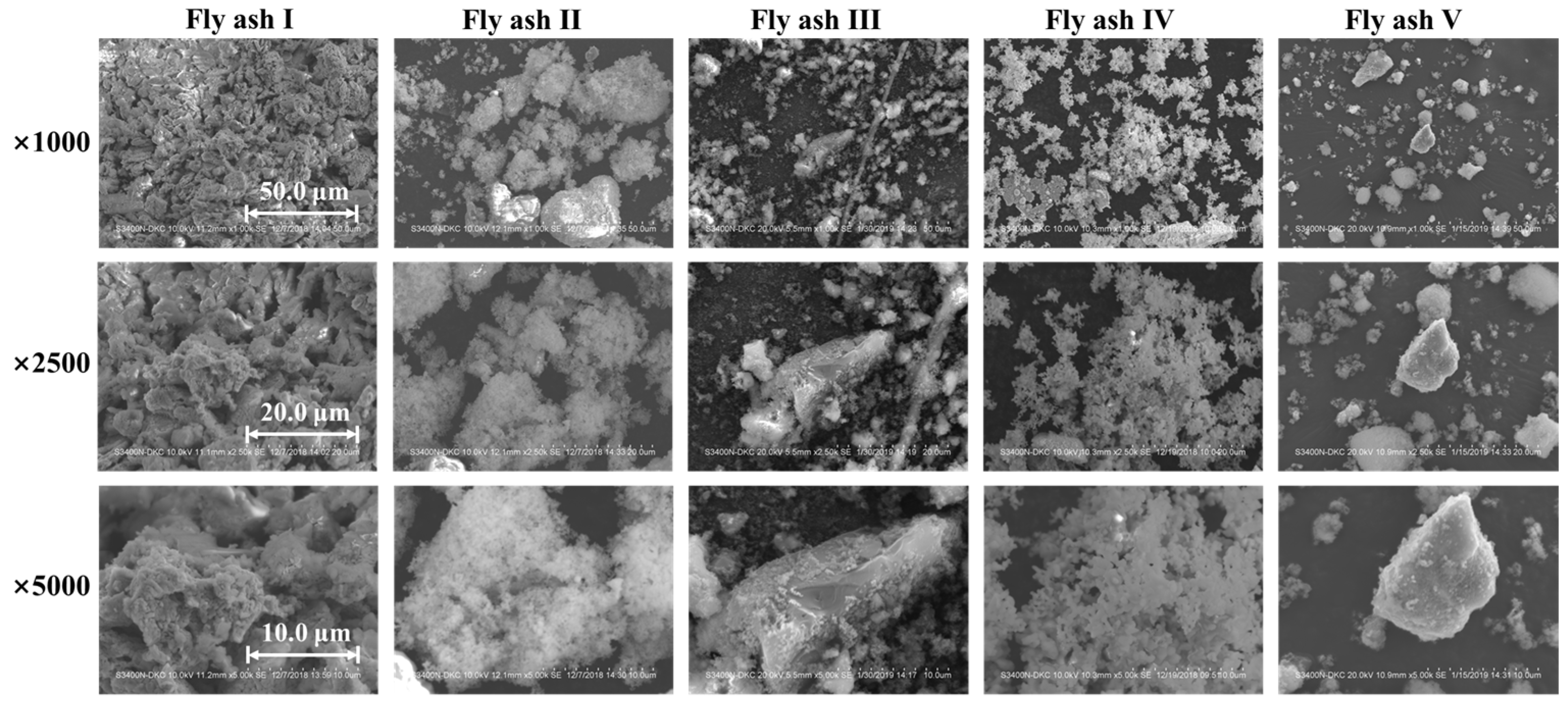
Particle morphology plays a critical role in the agglomeration of fly ash particles and their adhesion to the catalyst. In this study, SEM was used to analyze the morphology of various sintered fly ashes (Fly ash I~V, collected from different sintering machines), as shown in Figure 1. The figure shows that the sintered fly ash has a loose cotton-like appearance with a fluffy, multi-branched structure. This contrasts sharply with the spherical fly ash particles from power plant flue gas [24]. The morphological characteristic of sintered fly ash makes it prone to agglomeration under microscopic forces and macroscopic actions such as collision, adsorption, and cross-linking. In contrast, the catalyst surface typically has a porous, rough morphology. The distinct morphological features of both fly ash and the catalyst promote efficient adsorption of sintered fly ash onto the catalyst surface. This process promotes bridge formation and gradual aggregation, eventually causing catalyst blockage.
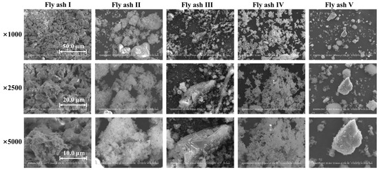
Figure 1.
Scanning electron microscope of sintered fly ash from various flue gases.
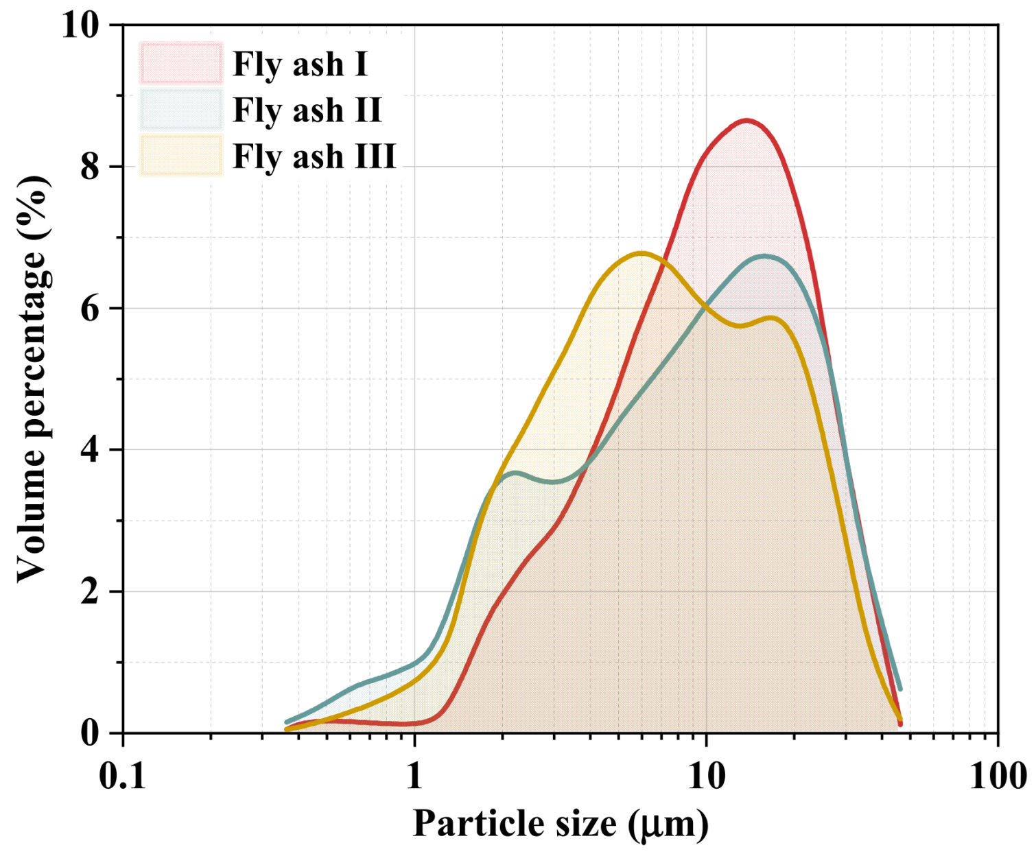
Furthermore, the particle size distribution of sintered fly ash I, II, and III was tested, and the volume percentages are presented in Figure 2. The results showed that the average particle size of the measured sintered fly ashes was around 10 μm. The average particle sizes of sintered fly ash I and II range from 12.6 μm to 13.7 μm, while sintered fly ash III has an average size of 8.3 μm, with 50% of the particles smaller than 10 μm. Although variations exist in the particle size distribution of fly ash from different sintering machines, smaller particle sizes generally increase adhesion and agglomeration. Ultrafine particles may penetrate catalyst pores, potentially hindering pollutant transfer and causing catalyst poisoning and deactivation.
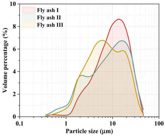
Figure 2.
Particle size distribution of different sintered fly ashes.
2.2. Composition and Contamination Characteristics
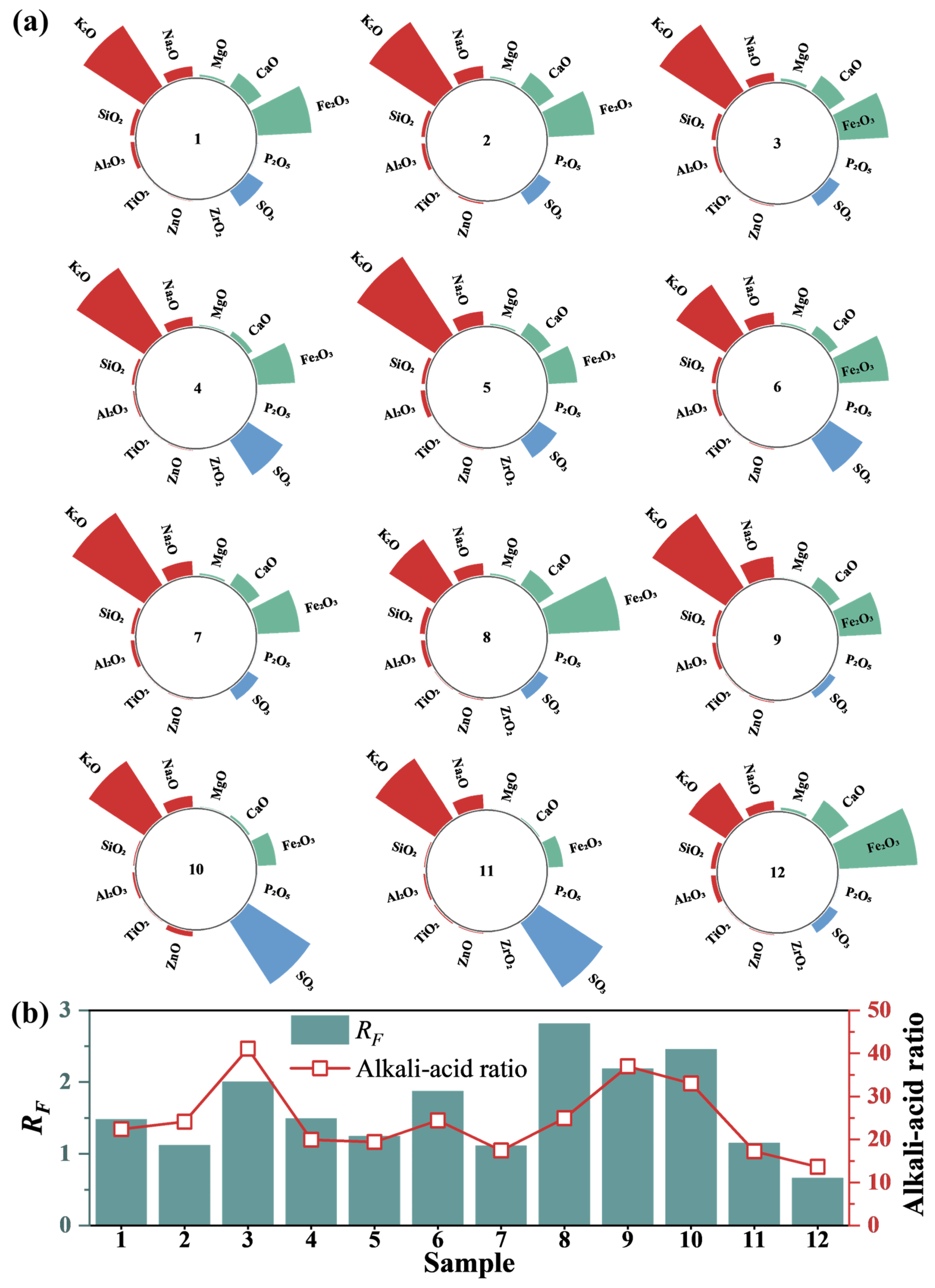
Variations in sintering ingredients result in significant differences in fly ash composition from different sintering machines. A semi-quantitative analysis of fly ash components from 12 sintering machines was conducted using XRF, as shown in Figure 3a. Despite marked differences in fly ash emissions from various sintering machines, the primary constituents of all fly ashes are alkaline oxides (e.g., K2O, Na2O, CaO, MgO) and Fe2O3. The highest concentrations of these components in different sintered fly ashes can reach 50.81%, 42.82%, 11.29%, 12.54%, and 1.54%, respectively, with a total maximum content of 89.09%. Among them, Fe2O3 primarily originates from iron ore, while CaO is mainly derived from sintering ingredients. Alkali metal oxides such as potassium and sodium also have high content, ranging between 20% and 50%. This is primarily due to the significant increase in imported ore in recent years, which often contains high alkali metal content, especially potassium and sodium oxides. In the sintering industry, alkali metals are typically denoted by their “alkali load”, which refers to the total amount of alkali metals introduced per ton of iron in the blast furnace (kg/t of iron). Compared to foreign steel plants, major Chinese steel factories face more serious alkali load issues, posing significant risks to the safe and stable operation of the SCR system.
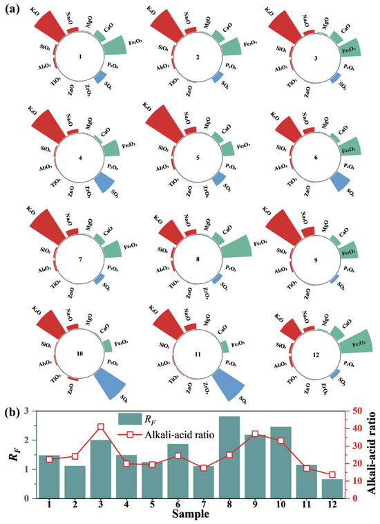
Figure 3.
(a) Composition test of sintered fly ash. (b) Contamination characteristics.
Fly ash properties are closely related to factors such as chemical composition and ambient atmosphere. The oxides in fly ash can be divided into two categories: acidic oxides (e.g., SiO2, Al2O3) and alkaline oxides (e.g., K2O, Na2O, CaO, MgO). Studies have examined the impact of coal ash, biomass ash, and coal gas fly ash composition on ash fusion. For example, the ash fusion temperature of different coals in China varies significantly with the chemical composition of the coal ash. The lowest fusion temperature is less than 1100 °C, while the highest exceeds 1600 °C. The silicon–aluminum ratio, acid–base ratio, silicon ratio, and iron–calcium ratio all significantly influence ash fusion and slagging properties. Alkali metals significantly affect the melting point of the mixture. Although few studies focus on sintered fly ash, existing research provides a reference for analyzing its adhesion properties. Research indicates that Na2O content is a key factor influencing the fouling characteristics of coal ash.
Based on fly ash composition, the alkali–acid ratio and fouling factor (RF) of various sintered fly ash samples were calculated, as shown in Figure 3b. Fouling characteristics are categorized by RF values: RF < 0.2 indicates slight fouling, 0.2–0.5 indicates moderate fouling, 0.5–1.0 indicates strong fouling, and >1.0 indicates severe fouling. Results show a strong correlation between the RF values of the 12 fly ash samples and the alkali–acid ratio. Additionally, all fly ash samples had RF values exceeding 1.0, indicating severe fouling.
2.3. Laboratory Heating Experiments
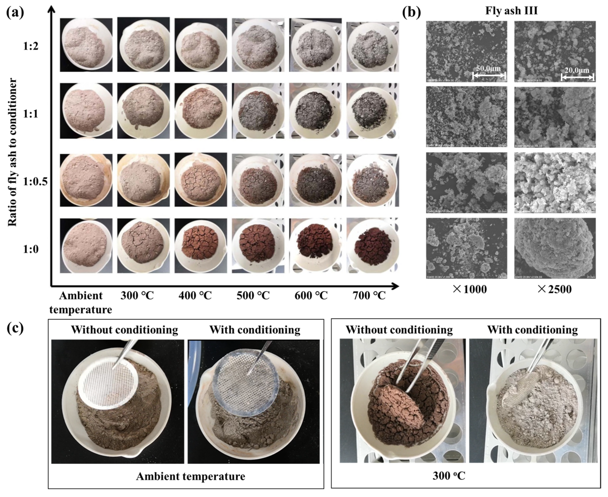
Previous studies demonstrate that the stickiness of fly ash is composition dependent. Although modifying fly ash composition at its source poses engineering challenges, it is feasible to alter the properties of sintered fly ash by introducing particulates with different properties into the flue gas. Consequently, a preliminary laboratory study was conducted to examine the effects of adding an alkali-based conditioner (commercial calcium carbonate powders) to sintered fly ash (using fly ash III as an example). The physical changes in mixed samples of sintered fly ash and conditioner, at varying ratios (1:0, 1:0.5, 1:1, 1:2) and different temperature conditions, are shown in Figure 4.
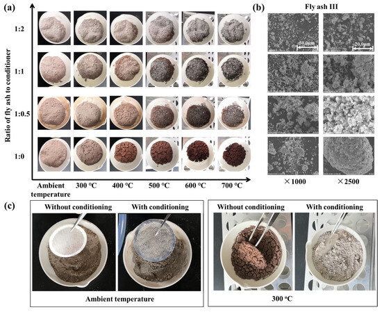
Figure 4.
(a) Heating of sintered fly ash/conditioner mixture. (b) SEM morphology of samples under heating condition at 300 °C. (c) Qualitative analysis of plate hole stickiness.
Figure 4a shows that as heating temperatures increase, the hue of the fly ash sample progressively darkens. This change largely results from the absence of an inert, oxygen-free environment during heating. Iron within the fly ash undergoes redox reactions under these conditions, forming different iron oxides. The color deepens as iron oxidizes to form Fe2O3 (hematite). The addition of calcium carbonate powders also altered the mixture’s color. Increasing the amount of calcium carbonate powders causes the mixture to decolorize due to Ca-Fe oxide interactions. Notably, fly ash samples without conditioner exhibited significant agglomeration during heating. In contrast, samples mixed with conditioner showed reduced agglomeration, and the effect was further diminished with higher conditioner concentrations.
The denitration catalyst typically operates at approximately 300 °C. Therefore, mixed samples heated to this temperature underwent micro-morphological analysis, and SEM scan results are shown in Figure 4b. Without conditioner (at a 1:0 ratio), sintered fly ash forms noticeable agglomerates. However, with the addition of conditioner, fly ash particles disperse, preventing the formation of large granules and reducing particle size. As conditioner concentration increases, particle size decreases further, and agglomeration and slab formation are further reduced. These results suggest that the conditioner plays a crucial role in isolating and physically modifying fly ash particles in the mixture.
To investigate the changes in the stickiness of fly ash, a qualitative analysis experiment using a metal mesh wall hanging was adopted. A stainless-steel mesh was placed in a dish, and the fly ash’s tendency to stick to the mesh was observed under ambient conditions, as shown in Figure 4c. While ash samples showed minimal agglomeration on the mesh at ambient temperature, unconditioned sintered fly ash adhered and formed agglomerates on the mesh after 30 min of heating at 300 °C. This observation supports empirical evidence that catalyst blockage worsens only while the heating system is operational and stops after shutdown. This emphasizes the critical role of temperature in influencing both fly ash viscosity and catalyst obstruction. In contrast, conditioned samples exhibited minimal stickiness even at 300 °C. These experiments qualitatively represent fly ash deposition on catalyst surfaces, highlighting the potential of particle conditioning to reduce sintered fly ash stickiness within catalyst channels.
2.4. Particle Conditioning in Application
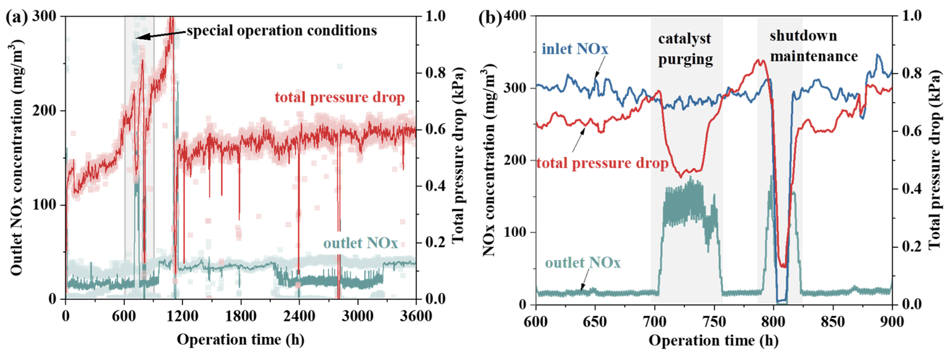
Based on fly ash property tests and laboratory heating experiments, further research on particle conditioning was conducted using a 230 m2 sintering machine. Although the catalyst’s pressure drop significantly affects the system’s safety and economic efficiency, its impact on NOx emissions remains unclear. Therefore, the relationship between catalyst pressure drop and NOx emission levels before and after renovation was examined, as shown in Figure 5. The data show no clear correlation between NOx emission concentration and the system’s operational pressure drop. Over 1000 h, despite significant catalyst blockage and a sharp increase in total system pressure drop, NOx emission concentration remained stable. This suggests that the catalyst remained active, allowing normal denitrification reactions to occur. Fly ash deposition on the honeycomb walls was identified as the main cause of performance degradation [25]. However, when blockage occurs mainly in the flow area of the catalyst’s honeycomb pores, its impact on the microstructure is minimal. Consequently, gas molecules can still diffuse into the catalyst pores and react as needed. A focused analysis between 600 h and 900 h shows a significant pressure drop during catalyst purging, accompanied by a rise in NOx emissions. Moreover, although catalyst purging temporarily reduces pressure drop, it quickly rises again post-blowing, indicating that this method does not effectively prevent long-term blockage. In fact, following occurrences of catalyst blockage, efforts were made to mitigate the issue by utilizing acoustic wave soot blowers. However, even with increased acoustic intensity, significant improvement in reducing catalyst blockage has been difficult to achieve.
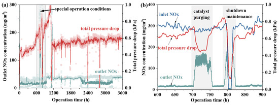
Figure 5.
(a) Catalyst pressure drop vs. NOx emissions. (b) Pressure drop vs. NOx concentration under special operation conditions.
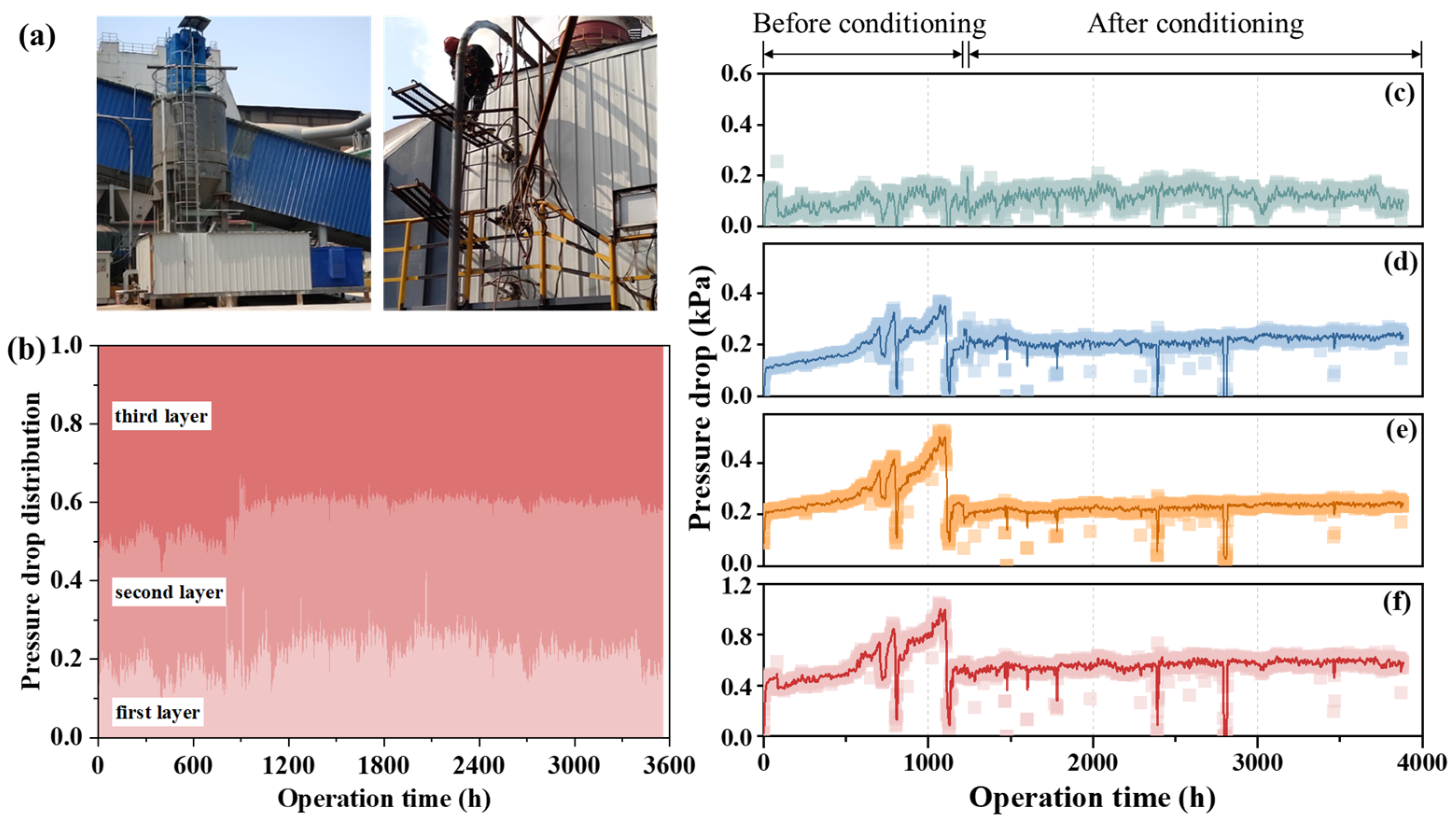
A particle conditioning system was developed for the described SCR denitrification process. Figure 6a displays an on-site photograph of this conditioning device. According to the characteristics of flue gas, the conditioner is formulated and stored in the powder silo. Through a dedicated unloading and mixing device, combined with a dilute phase pneumatic conveying system, the conditioner powder is transported to the mixing system. The mixing point is positioned upstream of the SCR system. A specialized gas–solid two-phase high-pressure spray gun is employed to evenly mix the conditioner powder into the flue gas. The conditioner interacts with the sintered fly ash in the flue and changes the properties of the sintered fly ash. The conditioner injection rate can be dynamically adjusted via the unloading and conveying system. Figure 6b shows the pressure drop distribution across each catalyst layer before and after renovation. Notably, the pressure drop increases progressively across the catalyst layers, with the first layer showing the lowest drop and the third the highest. This gradient is due to larger fly ash particles cleansing the first layer, reducing the deposition of smaller particles and subsequent blockages. As flue gas pressure decreases downstream, the cleansing effect diminishes, leading to a higher pressure drop in the third layer.

Figure 6.
(a) On-site photograph of particle conditioning device. (b) Pressure drop composition of each catalyst layer. (c–f) Pressure drop of the first, second, third catalyst layers, and the total pressure drop.
Figure 6c–f shows the pressure drop trends across the first, second, and third catalyst layers, along with the total pressure drop, before and after particle conditioning. The figures clearly show that before particle conditioning, the pressure drop across the three catalyst layers increased from 400 to 500 Pa to around 1100 Pa. This increase, caused by the gradual deposition of fly ash on the catalyst’s surface and pores, led to system failure. Specifically, Figure 6c shows a consistent pressure drop in the first layer, remaining at about 100 Pa before and after conditioning. This consistency indicates that the first catalyst layer was mostly unaffected by blockages. In contrast, Figure 6d,e shows significant pressure drop increases between 0 and 1000 h in the second and third catalyst layers. Notably, the third layer experienced a steeper increase than the second, indicating more severe blockage in the third layer.
After particle conditioning was applied, the pressure drops in both the second and third layers stabilized at about 200 Pa, indicating that further blockages were prevented. As a result, the total pressure drop across the denitrification system stabilized between 400 and 500 Pa.
To clarify the effectiveness of the particle conditioning system in improving catalyst blockage, an analysis was conducted on the changes in catalyst pressure drop before and after the operation of the conditioning system, as shown in Figure 6f. Prior to the operation of the conditioning system, the gradual adhesion and deposition of fly ash on the catalyst surface and in the pores caused the pressure difference across the three-layer catalyst to increase from 400 to 500 Pa to nearly 1100 Pa, rendering the system inoperable (around 1000 h in Figure 6f). During sintering machine maintenance, the catalyst was cleaned. After the SCR system and particle conditioning system were reactivated, fly ash adhesion on the catalyst surface was significantly reduced. After more than 100 days of continuous operation, the pressure difference remained stable below 600 Pa, a significant improvement compared to pre-conditioning, effectively solving the blockage issue in the denitrification catalyst for sintering flue gas.
3. Experimental Methods
3.1. Characterization of Ash Properties
Particle size and composition of fly ash significantly influence its stickiness. A laser particle size analyzer (Mastersizer 2000, Malvern, UK) was used to analyze the particle size distribution of typical ash samples and understand the blockage mechanism of sintered fly ash in catalyst pores. X-ray fluorescence spectroscopy (XRF, S4 PIONEER X, Bruker, Karlsruhe, Germany) was then used to perform a semi-quantitative analysis of the sintered fly ash composition from several denitrification projects. Research has shown that fly ash contamination characteristics are closely related to the content of four key alkaline oxides. Thus, fly ash stickiness was evaluated based on varying ash compositions. The RF [26], a measure derived from the alkali–acid ratio, was used to characterize fly ash stickiness, incorporating additional parameters to account for interactions between fly ash components and the conditioning process.
where B represents the alkaline component content in coal ash, A represents the acidic component content in coal ash, and Fe2O3, SiO2, etc., represent the mass percentage of various ash components on a dry basis.
Building on the understanding of fly ash stickiness, the changes in sintered ash’s physical properties after adding conditioning agents were investigated. Laboratory experiments used alkali-based absorbents mixed with sintered ash. Instruments employed included electronic balances, box resistance furnaces, and temperature controllers. Ash samples were collected from the fly ash captured by four electrostatic precipitators (ESP) at a steel plant in Shandong. The conditioning agent was an alkaline absorbent from a specific flue gas desulfurization project. The absorbent was added to the sintered fly ash in different ratios (1:0, 1:0.5, 1:1, and 1:2) and stirred uniformly to ensure proper mixing without grinding. The oven was preheated to 300–700 °C, then the fly ash-absorbent mixture was quickly inserted and heated for over 20 min to ensure thorough processing. A scanning electron microscope (SEM, HITACHI S-3400N, HITACHIS, Tokyo, Japan) was used to analyze the appearance of samples before and after treatment, which confirmed the mixing uniformity as well.
3.2. Field Test
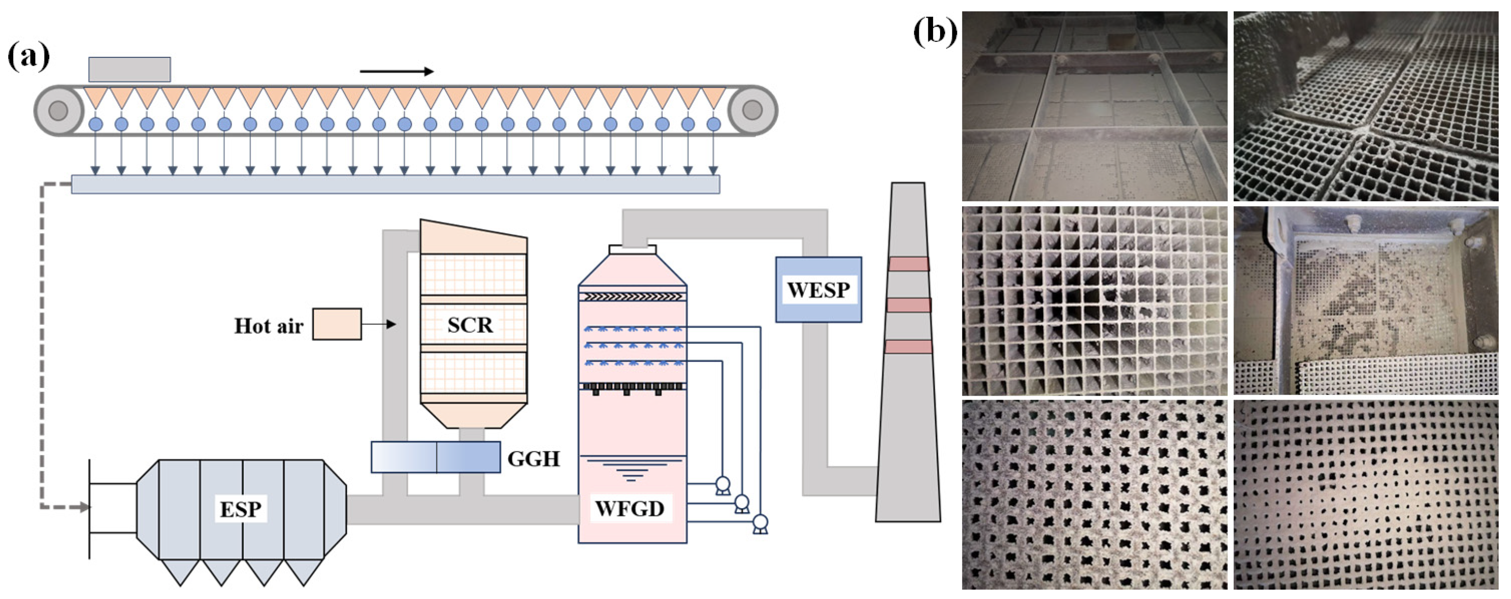
In engineering applications, sintering machines are typically equipped with ultra-low emission systems for desulfurization, denitrification, and dust removal. Figure 7a illustrates a technical route where denitrification occurs before desulfurization. In this system, flue gas flows through an ESP, an SCR system, a WFGD, and finally a WESP. After purification, the flue gas is released into the chimney. After ESP treatment, the dust concentration in the sintering flue gas averages 80–100 mg/m3, while the temperature decreases to 120–150 °C. The SCR system, located between the ESP and WFGD, requires a temperature range of 280–350 °C for optimal operation. Therefore, the sintering flue gas temperature must be increased before entering the SCR system. This temperature adjustment is typically carried out by blending the flue gas with hot air from coal gas combustion. To optimize energy utilization, a rotary gas-to-gas heat exchanger (GGH) is installed at the SCR outlet. Despite these measures, challenges have arisen with the SCR system in real applications.

Figure 7.
(a) Technical route of denitrification before desulfurization. (b) Photos of catalyst blockage.
Building on the SCR issues mentioned, the technical route of sintering flue gas purification largely adopts the route used in coal-fired power plants. After retrofitting the SCR system for sintering flue gas denitrification, a significant increase in the catalyst bed pressure drop was observed, peaking at 1200 Pa. After system shutdown and inspection, varying degrees of blockage were found in the SCR catalyst. Fly ash particles adhered to the honeycomb catalyst and obstructed its channels. These depositions of ash continued their incursion into the channels until fully blocking them, as depicted in Figure 7b, severely affecting the system’s operational safety and stability.
To address the catalyst blockage issue in the SCR system, a 230 m2 sintering machine was selected for field testing in this study. A particle conditioning system was installed at the SCR inlet, and the pressure drop before and after conditioning was continuously monitored online to evaluate the system’s reliability.
4. Conclusions
Upon an in-depth analysis of sintered fly ash characteristics under various conditions, this study proposes an innovative particle conditioning approach to mitigate the catalyst blockage in sintering flue gas. It highlights the technical route of denitrification before desulfurization. The key findings of this research are summarized as follows:
- (1)
- The composition and morphology of sintered fly ash are intrinsic factors contributing to catalyst blockage. Sintered fly ash is primarily composed of K2O, Fe2O3, Na2O, and CaO, with alkali metal oxides, particularly potassium and sodium, accounting for 20% to 50%. The distinct morphological attributes of the fly ash and the catalyst surface increase the tendency for fly ash adhesion on the catalyst.
- (2)
- Heating conditions are an extrinsic factor contributing to catalyst blockage. Under ambient conditions, sintered fly ash does not agglomerate, but significant agglomeration occurs as the temperature increases. Particle conditioning effectively reduces this tendency for agglomeration.
- (3)
- Field tests show that catalyst activity remains unaffected even under severe blockage conditions. The pressure drop across the catalyst layers increases progressively, with the first layer showing the lowest drop and the third the highest. After particle conditioning, the pressure drop remains consistently below 600 Pa.
Author Contributions
Conceptualization, D.S., Z.Y. and C.Z. (Chenghang Zheng); data curation, P.L.; funding acquisition, L.C., Z.Y. and C.Z. (Chenghang Zheng); investigation, D.S., C.Z. (Can Zhou) and L.C.; writing—original draft, D.S. and Y.Y.; writing—review and editing, Z.Y., Y.W. and C.Z. (Chenghang Zheng). All authors have read and agreed to the published version of the manuscript.
Funding
This work was supported by the National Key R&D Program of China (No. 2023YFC3707005), National Natural Science Foundation of China (52476143), and Youth Innovation Teams in Higher Education Institutions of Shandong Province (2023KJ064).
Data Availability Statement
Data are contained within the article.
Conflicts of Interest
The authors declare no conflicts of interest.
References
- Tang, L.; Xue, X.; Jia, M.; Jing, H.; Wang, T.; Zhen, R.; Huang, M.; Tian, J.; Guo, J.; Li, L. Iron and steel industry emissions and contribution to the air quality in China. Atmos. Environ. 2020, 237, 117668. [Google Scholar] [CrossRef]
- Zhang, X.H.; Feng, P.; Xu, J.R.; Feng, L.B.; Qing, S. Numerical research on combining flue gas recirculation sintering and fuel layered distribution sintering in the iron ore sintering process. Energy 2020, 192, 116660. [Google Scholar] [CrossRef]
- Zhu, T.; Wang, X.; Yu, Y.; Li, C.; Yao, Q.; Li, Y. Multi-process and multi-pollutant control technology for ultra-low emissions in the iron and steel industry. J. Environ. Sci. 2023, 123, 83–95. [Google Scholar] [CrossRef]
- Cui, L.; Liu, M.; Yuan, X.; Wang, Q.; Ma, Q.; Wang, P.; Hong, J.; Liu, H. Environmental and economic impact assessment of three sintering flue gas treatment technologies in the iron and steel industry. J. Clean. Prod. 2021, 311, 127703. [Google Scholar] [CrossRef]
- Chen, H.; Luo, M.; Wang, Y.; Zhang, Q.; Liu, Y. Influence of Coal-Fired Boiler Fly Ash on SCR Denitration Catalysts and Preventive Measures. J. Combust. Sci. Technol. 2017, 23, 200–211. [Google Scholar]
- Xu, Y.; Zhang, Y.; Liu, F.; Shi, W.; Yuan, J. CFD analysis on the catalyst layer breakage failure of an SCR-DeNOx system for a 350 MW coal-fired power plant. Comput. Chem. Eng. 2014, 69, 119–127. [Google Scholar] [CrossRef]
- Feng, H.; Wang, C.; Huang, Y. Particle deposition behaviors of monolithic De-NOx catalysts for selective catalytic reduction (SCR). Korean J. Chem. Eng. 2017, 34, 2832–2839. [Google Scholar] [CrossRef]
- Heiredal, M.L.; Jensen, A.D.; Thøgersen, J.R.; Frandsen, F.J.; Friemann, J.-U. Pilot-scale investigation and CFD modeling of particle deposition in low-dust monolithic SCR DeNOx catalysts. AIChE J. 2013, 59, 1919–1933. [Google Scholar] [CrossRef]
- Yang, J.; Ma, H.; Yamamoto, Y.; Yu, J.; Xu, G.; Zhang, Z.; Suzuki, Y. SCR catalyst coated on low-cost monolith support for flue gas denitration of industrial furnaces. Chem. Eng. J. 2013, 230, 513–521. [Google Scholar] [CrossRef]
- Yu, C.; Si, F.; Ren, S.; Jiang, X. Experimental and numerical predictions of ash particle erosion in SCR monolithic catalysts for coal-fired utility boilers. Korean J. Chem. Eng. 2017, 34, 1563–1575. [Google Scholar] [CrossRef]
- Jiang, Y.; Lai, C.Z.; Li, Q.Y.; Gao, W.Q.; Yang, L.; Yang, Z.D.; Lin, R.Y.; Wang, X.W.; Zhu, X.B. The poisoning effect of KCl and K2O on CeO2-TiO2 catalyst for selective catalytic reduction of NO with NH3. Fuel 2020, 280, 118638. [Google Scholar] [CrossRef]
- Jiang, Y.; Shi, W.Y.; Lai, C.Z.; Gao, W.Q.; Yang, L.; Yu, X.X.; Yang, Z.D.; Lin, R.Y. The deactivation effect of Na2O and NaCl on CeO2-TiO2 catalysts for selective catalytic reduction of NO with NH3. J. Energy Inst. 2020, 93, 1332–1340. [Google Scholar] [CrossRef]
- Jiang, Y.; Yang, L.; Liang, G.T.; Liu, S.J.; Gao, W.Q.; Yang, Z.D.; Wang, X.W.; Lin, R.Y.; Zhu, X.B. The poisoning effect of PbO on CeO2 -MoO3/TiO2 catalyst for selective catalytic reduction of NO with NH3. Mol. Catal. 2020, 486, 82–91. [Google Scholar] [CrossRef]
- Zhuang, K.; Yao, J.; Wu, B.; Ma, X.; Shen, Y.; Du, M.; Zhong, P. Numerical Simulation of the Distribution Discrepancies between Flue Gas Flow Field and Fly Ash Concentration Field in SCR De-NOx Reactor. Electr. Power 2018, 51, 137–142. [Google Scholar]
- Yue, P.; Lei, Y.; Chen, S.; Liu, X.; Meng, L.; Gu, X. Experimental investigation on pressure drop characteristics and efficiency of large particle ash interceptor for SCR denitration system. Therm. Power Gener. 2022, 51, 119–125. [Google Scholar]
- Wang, F.; Li, W. Analysis and Treatment of Ash Deposition in SCR Denitration Equipments of W Boiler. Electr. Power 2019, 52, 178–184. [Google Scholar]
- Zheng, Y.; Jensen, A.D.; Johnsson, J.E.; Thøgersen, J.R. Deactivation of V2O5-WO3-TiO2 SCR catalyst at biomass fired power plants: Elucidation of mechanisms by lab-and pilot-scale experiments. Appl. Catal. B Environ. 2008, 83, 186–194. [Google Scholar] [CrossRef]
- Cheng, X.; Bi, X.T. A review of recent advances in selective catalytic NOx reduction reactor technologies. Particuology 2014, 16, 1–18. [Google Scholar] [CrossRef]
- Jin, L.; Xie, X.; Huang, F.; Lu, C.; Zhou, J.; Song, Y. Experimental Study on the Technology of Large Particle Ash Interception for SCR De-NOx Equipment. Electr. Power 2018, 51, 156. [Google Scholar]
- Qi, L.; Yuan, Y. Characteristics and the behavior in electrostatic precipitators of high-alumina coal fly ash from the Jungar power plant, Inner Mongolia, China. J. Hazard. Mater. 2011, 192, 222–225. [Google Scholar] [CrossRef]
- Mahalik, K.; Sahu, J.; Patwardhan, A.V.; Meikap, B. Kinetic studies on hydrolysis of urea in a semi-batch reactor at atmospheric pressure for safe use of ammonia in a power plant for flue gas conditioning. J. Hazard. Mater. 2010, 175, 629–637. [Google Scholar] [CrossRef] [PubMed]
- Qi, L.; Zhang, Y. Effects of water vapor on flue gas conditioning in the electric fields with corona discharge. J. Hazard. Mater. 2013, 256, 10–15. [Google Scholar]
- Zheng, C.; Shen, Z.; Yan, P.; Zhu, W.; Chang, Q.; Gao, X.; Luo, Z.; Ni, M.; Cen, K. Particle removal enhancement in a high-temperature electrostatic precipitator for glass furnace. Powder Technol. 2017, 319, 154–162. [Google Scholar] [CrossRef]
- Zheng, C.H.; Liu, X.T.; Yan, P.; Zhang, Y.X.; Wang, Y.; Qiu, K.Z.; Gao, X. Measurement and prediction of fly ash resistivity over a wide range of temperature. Fuel 2018, 216, 673–680. [Google Scholar] [CrossRef]
- Lanza, A.; Usberti, N.; Forzatti, P.; Beretta, A. Kinetic and Mass Transfer Effects of Fly Ash Deposition on the Performance of SCR Monoliths: A Study in Microslab Reactor. Ind. Eng. Chem. Res. 2021, 60, 6742–6752. [Google Scholar] [CrossRef]
- Su, G.; Zhang, X.; Zhong, Y.; Wei, Y. Evaluation method for ash fouling characteristics of coals with high alkali content. Therm Power Gener. 2016, 45, 9–13. [Google Scholar]
Disclaimer/Publisher’s Note: The statements, opinions and data contained in all publications are solely those of the individual author(s) and contributor(s) and not of MDPI and/or the editor(s). MDPI and/or the editor(s) disclaim responsibility for any injury to people or property resulting from any ideas, methods, instructions or products referred to in the content. |
© 2024 by the authors. Licensee MDPI, Basel, Switzerland. This article is an open access article distributed under the terms and conditions of the Creative Commons Attribution (CC BY) license (https://creativecommons.org/licenses/by/4.0/).

