Article

Fabrication of Two-Dimensional B-Doped C3N4 Nanosheet-Encapsulated One-Dimensional Rod-like Mo-MOF-Derived MoS2 Heterojunctions for Enhanced Photocatalytic Ethanol Conversion and Synergistic Hydrogen Production

1
Instrumental Analysis Center, Taiyuan University of Technology, Taiyuan 030024, China
2
College of Materials Science and Engineering, Taiyuan University of Technology, Taiyuan 030024, China
3
School of Material and Chemical Engineering, Kaifeng University, Kaifeng 475004, China
*
Authors to whom correspondence should be addressed.
Catalysts 2024, 14(11), 833; https://doi.org/10.3390/catal14110833
Submission received: 12 October 2024 / Revised: 9 November 2024 / Accepted: 14 November 2024 / Published: 19 November 2024
(This article belongs to the Section Photocatalysis)

Abstract

:
The photocatalytic conversion of ethanol and the simultaneous development of hydrogen technology play a role in solving the energy crisis and reducing environmental pollution. In this research, rod-like M-MoS2 serves as a channel for charge transfer, leading to superior photocatalytic activity compared to H-MoS2. Further, two-dimensional (2D) B-doped C3N4 (BCN) nanosheets were anchored on the one-dimensional (1D) rod-like M-MoS2 surface to form a 1D/2D heterojunction, with M-MoS2/BCN-0.08 (mass ratio of M-MoS2:BCN of 0.08:1) exhibiting the highest photocatalytic performance. Under visible light irradiation, the ethanol conversion rate reached 1.79% after 5 h of photocatalytic reaction per gram of catalyst, while generating 421 μmol of 2,3-butanediol (2,3-BDO), 5460 μmol of acetaldehyde (AA), and 5410 μmol of hydrogen gas (H2). This different characterization provides evidence that a significant amount of photoinduced electrons generated in BCN under illumination conditions rapidly transfer to the conduction band (CB) of M-MoS2 through the rod-like structure of M-MoS2, and finally transfer to Pt to promote the production of hydrogen gas. The photoinduced holes in the valence band (VB) of M-MoS2 are rapidly consumed by ethanol upon transferring to BCN, effectively separating the photoinduced electron–hole pairs and resulting in superior photocatalytic performance.

Graphical Abstract

1. Introduction

Ethanol, as the most basic monohydric alcohol, is used to produce value-added chemical compounds. These compounds enable a number of various substances to be obtained, relating to large-scale final products and intermediates such as commodity chemicals (hydrogen, ethylene, acetaldehyde (AA), ethyl acetate, 2,3-butanediol (2,3-BDO), etc.). The use of photocatalytic technology to convert abundant monohydric alcohols into high value-added chemicals, while generating a large amount of hydrogen gas, exhibits significant potential for solving the energy and environmental pollution crises [1]. At present, the photocatalysts for converting ethanol are mainly TiO2, ZnS, and CdS [2,3,4]; however, these photocatalysts have the disadvantages of poor light absorption and low long-term stability. Thus, it is an urgent priority to develop new photocatalysts for photocatalytic ethanol conversion.
Due to its good visible light response, excellent thermal stability, and low cost, g-C3N4 has shown significant advantages in the field of photocatalysis [5,6,7,8]. For instance, carbon nitrides, including non-graphitic carbon nitrides, demonstrated high catalytic activity in the Knoevenagel reaction, synthesis of dimethyl carbonate via transesterification of ethylene carbonate, Friedel–Crafts acylation, oxidation of cyclic olefin intepoxides, etc. [9,10,11]. However, the inferior photogenerated electron–hole separation efficiency and limited active sites lead to the extremely unsatisfactory photocatalytic efficiency of the bare g-C3N4 [12,13,14]. Therefore, a series of modification methods, such as dimensionality control, doping, and heterostructure construction with other materials, have been implemented to boost the photocatalytic performance of g-C3N4 [15,16,17].
Metal–organic frameworks (MOFs), as a species of porous crystals with specific topological structures, are being widely used in gas adsorption, catalysis, sensing, and other fields [18,19]. Semiconductor materials, with nanorods, nanosheets, and hollow structures synthesized using MOFs as templates, can effectively improve the charge transfer efficiency and absorption properties in photocatalytic processes [20,21]. Therefore, metal sulfides derived from MOFs have unique advantages over traditional sulfides and are used to produce composites with g-C3N4, significantly facilitating charge transfer and enhancing the photocatalytic efficiency [22,23,24]. For example, Fan et al. derived a new hollow, cubic CoS structure from Co-ZIF-9 and successfully constructed S-C bonds between CoS and g-C3N4, achieving efficient hydrogen evolution [25]. Qi et al. designed C-doped Ni3S4/Ni2P hybrid co-catalysts decorated on g-C3N4 using Ni-MOF as a template, exhibiting a 10 times higher photocatalytic performance compared to the pristine g-C3N4 [26]. Hu et al. prepared a three-component C-Cu2-xS@ g-C3N4 heterojunction using HKUST-1 as a precursor and observed 23-fold enhanced activity in comparison to C3N4 [27].
Most recently, molybdenum disulfide (MoS2) has been widely employed for constructing heterojunctions with C3N4 due to its good electrical conductivity, broad light absorption range, and appropriate band gap [28,29]. For example, Nagaraja et al. synthesized MoS2 microflowers and g-C3N4 heterostructures using a one-pot solvothermal method, exhibiting significantly enhanced photocatalytic activity [30]. Li et al. successfully constructed a g-C3N4/Cu/MoS2 Z-type heterojunction with excellent photocatalytic activity employing the two-step calcination method [31]. As for the MOF-derived MoS2, an MoS2/CdS photocatalyst was constructed, and the Mo-MOF-derived MoS2 provided a sustainable cocatalyst for CdS [32]. In addition, Bi4O5Br2 was anchored onto the rod-like MOF-derived MoS2 to form a p-n heterojunction, which exhibited a distinctly improved photocatalytic performance [33]. However, the use of Mo-MOF-derived MoS2 and g-C3N4 to construct heterostructures for use as photocatalysts for efficient ethanol conversion has not been extensively studied.
In a previous work, a B-doped C3N4 nanosheet (BCN) was first synthesized and further combined with ZIF67, which exhibited an excellent photocatalytic performance [34]. Here, rod-shaped MoS2 was synthesized using a Mo-MOF rod-like structure as a template and 1D/2D heterostructures were further constructed with B-doped g-C3N4 nanosheets. The unique structure of the BCN nanosheets encapsulating the rod-like MoS2 resulted in an enhanced light absorption capability, displaying outstanding photocatalytic behavior. Moreover, a plausible reaction mechanism and a charge transfer pathway were also proposed according to the characterization information.

2. Results and Discussion

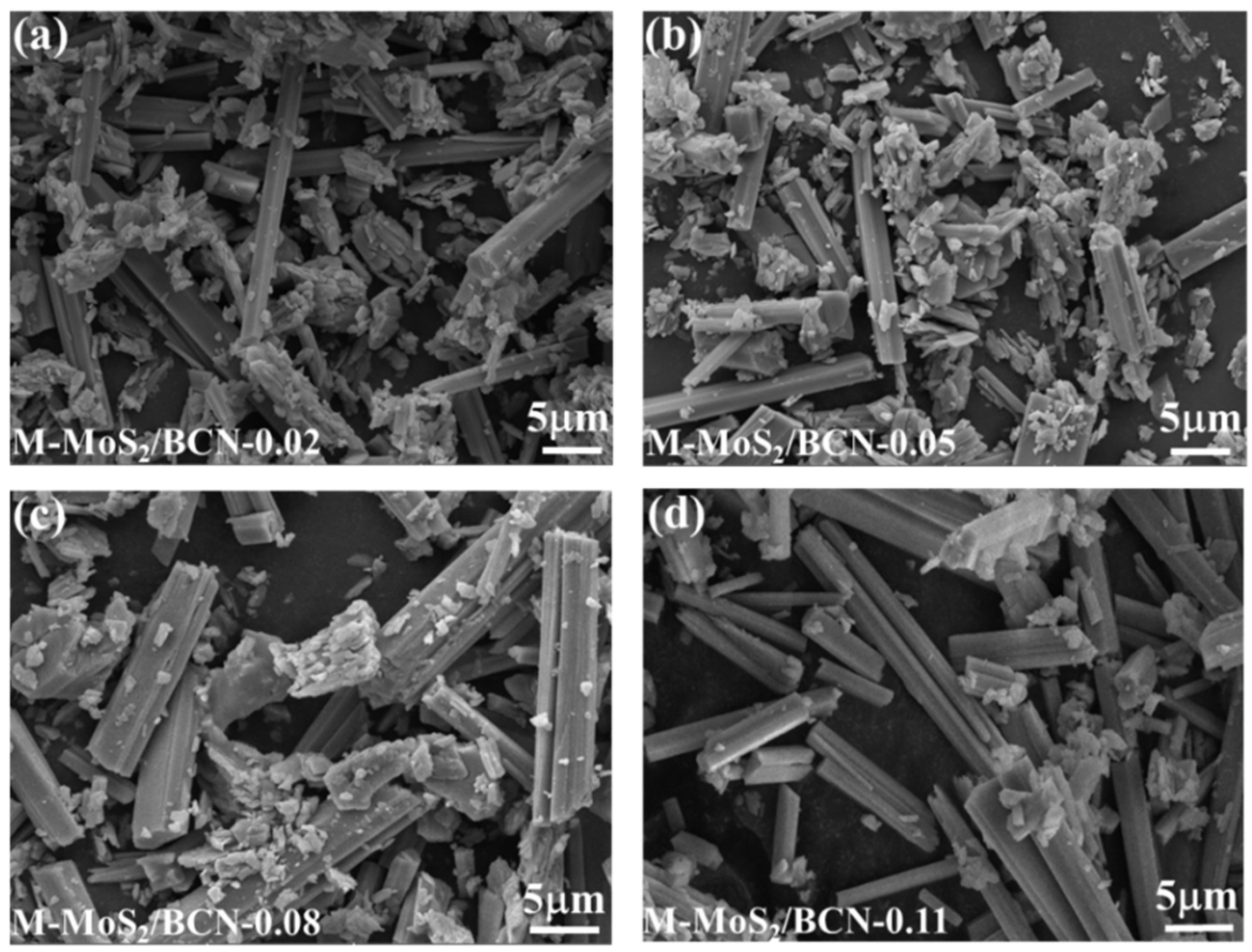
Figure 1a–c show the SEM images of H-MoS2, Mo-MOF, and M-MoS2, respectively. The hydrothermally synthesized MoS2 is an assembly of numerous nanosheets with severe aggregation. Furthermore, the synthesized Mo-MOF exhibits a rod-like structure with an interlocked arrangement and a smooth surface, indicating good dispersibility. Moreover, the M-MoS2 prepared using Mo-MOF as a template maintains the rod-like structure of Mo-MOF, with an interlocked arrangement of rod-like structures, demonstrating that the M-MoS2 inherits the excellent dispersibility from Mo-MOF. In order to investigate the effect of the changes in morphology on material properties, the photocatalytic hydrogen evolution performance of H-MoS2 and M-MoS2 was tested under the irradiation of a 300 W xenon lamp in a mixture of 45 mL ethanol and 5 mL aqueous solution (Figure 2a,b). The photocatalytic hydrogen evolution rate of the H-MoS2 synthesized by the conventional hydrothermal method is only 7.3 μmol g−1 h−1, while that of the M-MoS2 derived from Mo-MOF reaches 51.8 μmol g−1 h−1. Compared to H-MoS2, the unique rod-like structure of M-MoS2 serves as a channel for charge transfer, promoting the transport of photogenerated electron–hole pairs and thus resulting in an excellent photocatalytic activity. Figure 3a–d show the SEM images of the 1D/2D M-MoS2/BCN-X composites. It can be observed that all four synthesized composite materials exhibit a well-coated structure of BCN on M-MoS2, with a well-maintained rod-like morphology of M-MoS2. Different amounts of BCN are dispersed around the M-MoS2 in each sample, but overall, there is no significant difference in the morphology of the four samples.
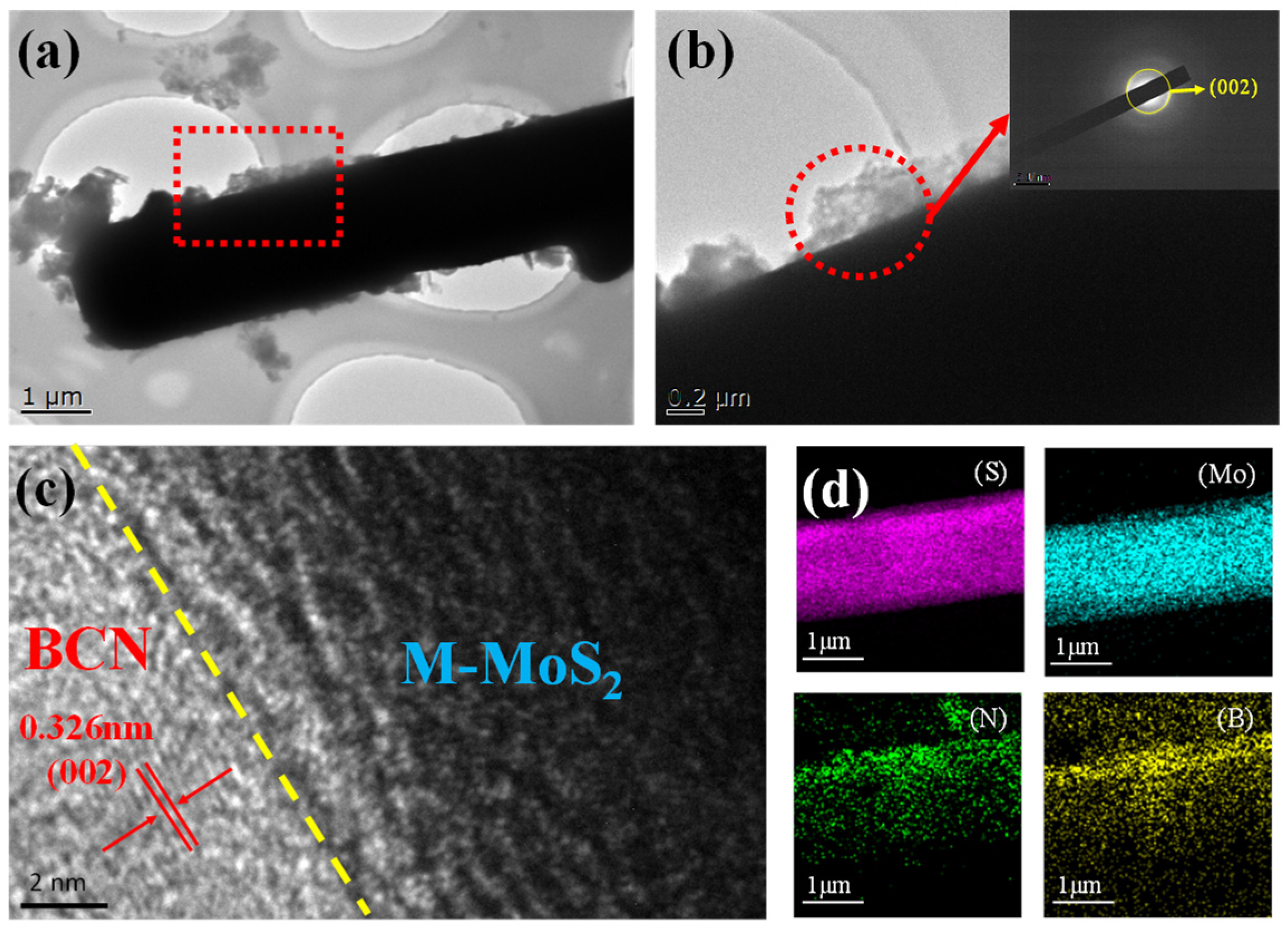
TEM characterization was performed on the M-MoS2/BCN-0.08 to investigate the morphological and structural features, as well as the nature of the bonding, between M-MoS2 and BCN in the composite material. As shown in Figure 4a, the rod-shaped M-MoS2 is dispersed with a large amount of BCN around it. The further magnification in Figure 4b reveals that the BCN surrounding M-MoS2 consists of only a few layers, appearing as translucent flakes, and the two are tightly bound together, revealing the presence of a close heterointerface between M-MoS2 and BCN. Figure 4c shows a high-resolution TEM image of the M-MoS2/BCN-0.08, with a measured lattice spacing of 0.326 nm, corresponding to the (002) plane of BCN [35]. However, the M-MoS2 has no apparent lattice spacing, which indicates the formation of an amorphous structure. Figure 4d displays a further STEM mapping of the examined samples, where the B and N elements are detected around the Mo and S elements, indicating that a large amount of thin and translucent BCN is anchored to the surface of the M-MoS2. Thus, a close contact heterointerface exists between M-MoS2 and BCN.
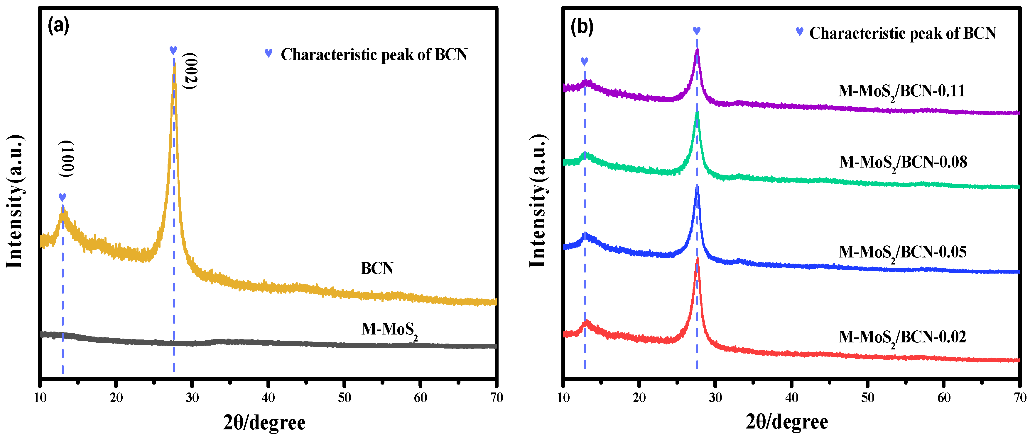
Figure 5a presents the XRD pattern of M-MoS2. The relatively poor crystallinity of the synthesized M-MoS2 provides evidence that M-MoS2 is amorphous, which is consistent with the HRTEM observation [36]. In addition, diffraction peaks corresponding to the (100) and (002) crystal planes of BCN can be observed in the entire pattern [37,38]. Figure 5b shows the XRD patterns of M-MoS2 and M-MoS2/BCN-X. Due to the weak crystallinity of M-MoS2, only the diffraction peaks of BCN are clearly observable.
Figure 6a displays the total XPS spectrum of the M-MoS2/BCN-0.08 composite material. The existence of the C, N, B, and Mo elements can be clearly identified. The further analysis of the B 1s fine spectrum in Figure 6b shows a binding energy peak at 191.7 eV, which corresponds to the typical N-B-N bond, confirming the existence of the BCN in the composite material [39]. Figure 6c presents the fine spectrum of Mo 3d, and two peaks at 229.3 eV and 232.3 eV corresponding to Mo 3d 5/2 and Mo 3d 3/2, respectively, can be confirmed, suggesting the presence of Mo4+ [40]. A weak peak at 235.8 eV is also observed, suggesting that a small amount of Mo4+ was slightly oxidized to Mo6+ during the material preparation process. Figure 6d shows the fine spectrum of S 2p, with two characteristic peaks at 162 eV and 163.2 eV, confirming the presence of S2− [41]. Through SEM, TEM, XRD, and XPS analyses, the successful preparation of M-MoS2 and M-MoS2/BCN-X was confirmed. M-MoS2 exhibits a unique rod-like structure, different from that produced via conventional hydrothermal methods, and demonstrates an excellent photocatalytic performance. M-MoS2/BCN-X, on the other hand, exhibits a structure where the nanosheets envelop the rod-like structure, with a well-defined heterojunction at the interface between the two components.
The main products, H2, AA, and 2,3-BDO, were determined through chromatographic analysis. The results showed that the prepared photocatalyst achieved the conversion of ethanol while generating a large amount of hydrogen gas. The conversion of ethanol per gram of catalyst within 5 h was calculated by measuring the amount of ethanol before and after the reaction using chromatography, as depicted in Figure 7a. The ethanol conversion of the BCN was 0.86%; after being combined with M-MoS2, the photocatalytic performance of the materials was improved to some extent. M-MoS2/BCN-0.08 exhibited the highest photocatalytic performance: the ethanol conversion reached 1.79%. This indicates that the material obtained through the combination of the M-MoS2 and BCN had a remarkably enhanced photocatalytic performance. Figure 7b presents the production rates of each substance per gram of photocatalyst per hour. It can be observed that the BCN exhibits weak photocatalytic activity, producing 534 μmol of hydrogen gas, 586 μmol of AA, and 43.9 μmol of 2,3-BDO per gram of BCN per hour under xenon lamp irradiation. When combined with M-MoS2, the resulting composite material exhibits a significantly enhanced photocatalytic performance, particularly M-MoS2/BCN-0.08 which generates 1082 μmol of hydrogen gas, 1092 μmol of AA, and 84.2 μmol of 2,3-BDO under xenon lamp irradiation. Based on the ethanol conversion rate and the yield of AA and 2,3-BDO within 10 h, the selectivity of the different photocatalysts for AA and 2,3-BDO after 10 h of reaction can be calculated using a carbon content balance (Equations (1)–(3)), as follows:
S A A = 2 n ( A A ) / 2 n ( e )
S 2,3 B D O = 4 n ( 2,3 B D O ) / 2 n ( e )
S o t h e r = ( 2 n e 2 n A A 4 n 2,3 B D O ) / 2 n ( e )
where n(AA) represents the amount of substance that produces AA within 10 h; n(2,3-BDO) represents the amount of substance that produces 2,3-BDO within 10 h; n(e) represents the amount of substance that converts ethanol within 10 h; and S represents the selectivity of the corresponding product. As shown in Figure 7c, the results indicate that the addition of M-MoS2 does not affect the selectivity of the products obtained after the ethanol conversion. The reason for this phenomenon is that the loading of M-MoS2 does not affect the desorption of the hydroxyethyl radical (•CH(OH)CH3). Therefore, compared with the pure BCN, the selectivity of the products formed by ethanol conversion remains unchanged.
To investigate the effect of the water content in solvents on the ethanol conversion and hydrogen production performance, the M-MoS2/BCN-0.08 photocatalysts were used for photocatalytic experiments in ethanol solutions with different water content. As shown in Figure 8a, it can be seen that when the water content is 0%, almost no hydrogen gas is generated and the substances generated by the conversion of ethanol are also extremely low. When a trace amount of aqueous solution is added to the solvent (5%), its photocatalytic performance is significantly enhanced, especially with a sharp increase in the generated hydrogen gas. The significant enhancement in the photocatalytic performance can be attributed to the fact that the addition of aqueous solutions consumes a large number of electrons, thereby promoting the production of hydrogen gas, and there are more holes that can oxidize ethanol to generate a large amount of •CH(OH)CH3. Moreover, the reduction potential of water is higher than that of 2,3-BDO and AA, so the addition of water can also effectively inhibit the reverse reaction of 2,3-BDO and AA. When the water content increases to 10%, the photocatalytic performance is enhanced and the selectivity of the products formed by ethanol conversion changes (Figure 8b). This is because the •CH(OH)CH3 generated by the hole oxidation of ethanol can interact with water to form hydrogen bonds, causing the partial desorption of •CH(OH)CH3 from the surface of the photocatalyst, and thereby promoting C-C bond coupling and generating a significant amount of 2,3-BDO. Therefore, the selectivity of 2,3-BDO is significantly improved. When the water content increases to 20%, the production of the hydrogen increases, while the conversion rate of the ethanol decreases. The reason for this phenomenon may be that the photocatalysts compete for the adsorption of water and ethanol. In Figure 8c, the electron paramagnetic resonance (EPR) spectrum shows a significant amount of •CH(OH)CH3 in the solution under light conditions for the generation of AA and 2,3-BDO. This indicates that the photocatalysts can convert a large amount of ethanol under illumination.
In order to evaluate the stability of the photocatalysts, three cycles of photocatalytic conversion of ethanol were conducted on M-MoS2/BCN-0.08, the photocatalyst with the best photocatalytic performance, with each cycle lasting for 5 h. As shown in Figure 9a, with the increase in the photocatalytic time and the number of cycles, the photocatalytic M-MoS2/BCN-0.08 still maintains good stability. The selectivity of the products formed by the ethanol conversion also remains stable (Figure 9b). The SEM and XRD tests on the photocatalyst after multiple cyclic tests are shown in Figure 9c and Figure 9d, respectively. It can be seen that the morphology and structure of the photocatalyst basically remained unchanged, indicating that the catalyst has good stability under the illumination conditions.
UV-Vis diffuse reflectance spectra were measured to investigate the optical absorption properties of the samples. From Figure 10a, it can be observed that the M-MoS2 derived from Mo-MOF exhibits moderate light absorption overall but shows a certain absorption in the visible and near-infrared range. In addition, the BCN exhibits a strong absorption ability in the UV region, with the absorption edge located at approximately 470 nm. Compared to the BCN, M-MoS2/BCN-0.08 shows a slight red shift in the absorption edge in the visible region, indicating an enhanced absorption ability in the visible range and a change in the bandgap. The bandgap widths of the materials were calculated using the Kubelka–Munk equation [42]. As shown in Figure 10b, the bandgap widths of the BCN, M-MoS2, and M-MoS2/BCN-0.08 are determined to be 2.62 eV, 2.32 eV, and 2.52 eV, respectively. The composite photocatalyst M-MoS2/BCN-0.08 has a smaller bandgap width compared to the BCN, indicating that M-MoS2 enhances the visible light absorption ability of the BCN and the narrower bandgap promotes the charge transfer capability and improves the photocatalytic activity of the material. Figure 10c displays the Mott–Schottky slopes of the BCN and M-MoS2, which are both positive, indicating that the two materials are typical n-type semiconductors. Further, the flat band potentials of the BCN and M-MoS2 are determined to be −0.9 V and −0.39 V, respectively, vs. the SCE based on the intercept results of the graph. Since the flat band potential of the n-type semiconductors is usually higher by about 0.2 V compared to the conduction band (CB) potential, the CB potentials of the BCN and M-MoS2 are calculated to be −1.1 V and −0.59 V (−0.86 and −0.35 V vs. NHE), respectively. Meanwhile, the VB potentials of the BCN and M-MoS2 are calculated to be 1.76 V and 1.97 V, respectively, using Eg = EVB − ECB.
To detect the electron transfer pathways in the composites, EPR measurements were carried out by dispersing the samples in a methanol solution containing a DMPO spin trapping agent. According to the concentration of the captured superoxide radicals in the solution, the electron concentration of the CB of the materials can be inferred, thus providing specific information on the electron transfer in the photocatalyst. As shown in Figure 10d, no significant DMPO-•O2 signals are observed for all three samples under the dark environment, while the DMPO-•O2 signals for all samples are significantly enhanced under the light conditions. This suggests that the electrons generated from the three groups of samples can reduce O2 to O2 in the solution under light irradiation. Among them, the M-MoS2/BCN-0.08 shows the strongest DMPO-•O2 signal, which illustrates that this composite generates the most electrons for O2 reduction under the same conditions. Therefore, the electrons on the CB of BCN continuously transfer to the CB of M-MoS2 during the photocatalytic process, providing evidence that a type II heterojunction between M-MoS2 and BCN is formed. Figure 10e displays the band structure of the M-MoS2 and BCN, illustrating the specific pathways for the electron–hole transfer during the photocatalytic process. The type II heterojunction constructed by these two materials effectively improves the separation of the photo-generated charge carriers, leading to an enhanced photocatalytic performance. To further investigate the recombination behavior of the photo-generated charge carriers, photoluminescence (PL) spectroscopy was employed to evaluate the lifetime of the charge carriers in different samples, as shown in Figure 10f. The M-MoS2 exhibited a strong PL emission peak at around 600 nm, while BCN showed a reduced emission peak compared to M-MoS2, indicating the shorter lifetime of the photo-generated charge carriers in both materials. For all composites of M-MoS2 with BCN with different ratios, a significant decrease in the PL intensity was observed, indicating that the heterojunction interface between M-MoS2 and BCN effectively accelerates the separation of the electron–hole pairs. Among all the composite materials, M-MoS2/BCN-0.08 exhibited the lowest PL intensity, indicating the longest lifetime of the photo-generated charge carriers, which corresponds to its excellent photocatalytic hydrogen evolution performance. The PL spectra suggest that the unique nanosheet-coated rod-like structure and the type II heterojunction formed by M-MoS2 and BCN can effectively spatially separate the photo-generated electron–hole pairs, thereby enhancing the lifetime of the charge carriers in the material.
Photoelectrochemical tests were conducted on M-MoS2, BCN, and M-MoS2/BCN-X to analyze the separation and transfer abilities of the photo-generated electron–hole pairs. As shown in Figure 11a, M-MoS2 and BCN exhibit low PC responses. However, the composites formed by the two show a significantly improved PC response, indicating that the heterojunction structure constructed by M-MoS2 and BCN effectively enhances the separation ability of the photo-generated charge carriers. The highest PC response for M-MoS2/BCN-0.08 also corresponds to its optimal photocatalytic hydrogen evolution performance. The impedance test results of the materials are shown in Figure 11b, where a bigger curvature radius in the impedance spectrum indicates a faster charge transfer resistance. Among them, the curve with the smallest curvature radius corresponds to M-MoS2/BCN-0.08, indicating that this material has the best separation and transfer ability of the photo-generated carriers. The LSV curves are shown in Figure 11c. Compared with the M-MoS2 and BCN, M-MoS2/BCN-X shows varying degrees of increased cathodic currents. The maximum cathodic current of the M-MoS2/BCN-0.08 may be caused by the rapid electron migration between the contact interface, implying that the heterojunction prompts the electron transfer and enhances the photocatalytic activity. The improvement in the performance is related to the rapid charge transfer at the material interface and the significant increase in the lifetime of the photo-generated charge carriers after the formation of the composite material. The rod-like structure of Mo-MoS2 can serve as a special channel for the charge transfer, resulting in a faster charge transfer rate after the transfer of electrons from BCN CB to M-MoS2 CB. The optimal electrochemical performance of the M-MoS2/BCN-0.08 is consistent with its best photocatalytic hydrogen evolution performance.
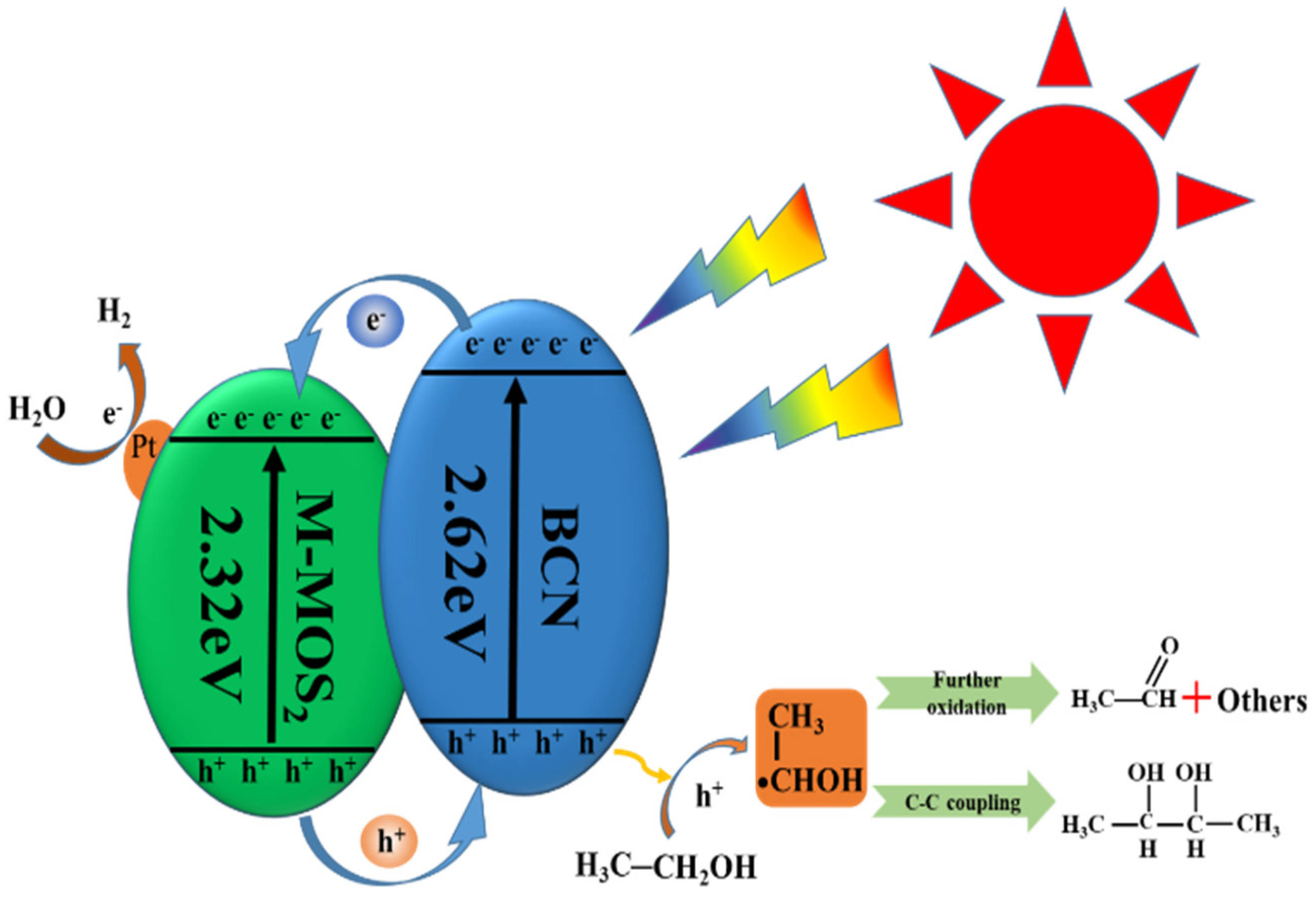
The proposed charge transfer mechanism of the 1D/2D M-MoS2/BCN-0.08 heterojunction under illumination conditions is presented in Figure 12. In comparison to MoS2 prepared using the conventional hydrothermal method, M-MoS2 exhibits a rod-like structure similar to Mo-MOF, with a large specific surface area and pore volume due to its spatial dispersion. This results in the exposure of more active sites, leading to superior photocatalytic performance. Additionally, the unique rod-like structure of M-MoS2 serves as a channel for charge transfer, facilitating faster electron transfer during the process. Moreover, M-MoS2 has a significant absorption ability throughout the visible light region, and the composite with BCN causes a redshift in the material, reducing the energy required for electron excitation in BCN. Furthermore, the reduced bandgap of the M-MoS2/BCN-0.08 enhances its visible light absorption capacity.
The charge transfer mechanism of the 1D/2D M-MoS2/BCN-0.08 heterojunction is further analyzed. Under illumination conditions, both the M-MoS2 and BCN generate photoinduced electron–hole pairs. Excited-state electrons migrate to the CB of M-MoS2 and BCN, leaving photoinduced holes in the corresponding VB. Due to the potential difference between the CB of the BCN and M-MoS2, the electrons in the CB of BCN spontaneously transfer to the CB of the M-MoS2. With the continuous progress of the reaction, the accumulated electrons on the CB of M-MoS2 react gradually with the adsorbed H+ to form atomic hydrogen. Then, atomic hydrogen migrates to Pt particles to form H2. During this process, ethanol acts to consume the photoinduced holes generated in the photocatalytic reaction system. The ethanol molecules adsorbed on the catalyst surface are first oxidized to •CH(OH)CH3, and then some of the •CH(OH)CH3 is desorbed onto the catalyst surface for C-C bond coupling to form 2,3-BDO. Some of the •CH(OH)CH3 that fails to be desorbed in a timely manner will be further oxidized to AA by more holes and finally will be oxidized to other substances such as acetic acid or CO2.
Compared to the normal hydrogen electrode (NHE), the CB potentials of M-MoS2 and BCN are −0.35 V and −0.9 V, respectively, indicating that both the M-MoS2 and BCN have sufficiently high levels of CB energy to drive the photocatalytic production of H2. The type II heterojunction formed by M-MoS2 and BCN effectively utilizes the photoinduced electrons generated by both materials. Moreover, the thin nanosheets of BCN and the unique rod-like structure of M-MoS2 allow for the uniform coverage of BCN on the surface of M-MoS2. During the photocatalytic hydrogen evolution process, the large amount of photoinduced electrons generated in BCN under illumination conditions rapidly transfer to the CB of M-MoS2 through the rod-like structure of M-MoS2, while the photoinduced holes in the VB of M-MoS2 are rapidly consumed by ethanol upon transferring to BCN and promote the generation of AA and 2,3-BDO, effectively separating the photoinduced electron–hole pairs and resulting in superior photocatalytic performance.

3. Materials and Methods

3.1. Synthesis of B-Doped g-C3N4 Nanosheets

The B-doped g-C3N4 nanosheets were prepared using a thermal polymerization and exfoliation method [43,44]. Specifically, 5 g of melamine (C3H6N6) and 40 mg of boric acid (H3BO3) were mixed and ground. Then, the collected powders were transferred to a covered alumina crucible, heated from room temperature to 550 °C at a rate of 5 °C/min in a muffle furnace, and soaked for 4 h. The obtained solid was fully ground to obtain a B-doped g-C3N4 nanosheet powder, which was then placed in an open alumina crucible and heated again under the condition of 500 °C for 2 h in a muffle furnace at a rate of 5 °C/min, resulting in B-doped g-C3N4 nanosheets.

3.2. Preparation of MoS2 Nanosheets (H-MoS2)

A total of 90 mg of thiourea (C2H5NS) and 50 mg of sodium molybdate dihydrate (Na2MoO4•2H2O) were mixed in 40 mL of deionized water, and the transparent solution was transferred to a 100 mL Teflon-lined autoclave and heated at 220 °C for 24 h. The black powder was collected, washed with deionized water three times, and dried in vacuum at 80 °C for 12 h to obtain H-MoS2.

3.3. Preparation of Rod-like Mo-MOF and Derived MoS2 (M-MoS2)

Then, 3.5 g of molybdenum trioxide (MoO3) and 1.66 g of imidazole (C3H4N2) were dissolved in 250 mL of deionized water, and the mixture was refluxed at 100 °C for 12 h. After that, the precipitate was collected by centrifugation. After washing three times with deionized water, Mo-MOF microrods were obtained by vacuum drying at 70 °C. M-MoS2 was prepared using Mo-MOF as a template. Specifically, 0.2 g of the prepared Mo-MOF and 1.6 g of thiourea (CH4N2S) were placed in separate open alumina crucibles, and the crucibles were placed downstream and upstream of a tubular furnace. After purging with N2 for 30 min to remove the oxygen from the furnace, the temperature was increased to 600 °C at a rate of 5 °C/min under an N2 atmosphere and maintained for 3 h to obtain the black M-MoS2.

3.4. Preparation of 1D/2D M-MoS2/BCN Heterostructure

The 1D/2D M-MoS2/BCN heterostructure was prepared using a mechanical grinding method that enables precise control of the material ratio. Specifically, 0.2 g of the prepared BCN and a certain amount of M-MoS2 were placed in a quartz grinding dish and thoroughly ground for 30 min to obtain M-MoS2/BCN-X, where X represents the mass ratio of M-MoS2 to BCN. Four different mass ratios of the composite materials were prepared, namely M-MoS2/BCN-0.02, M-MoS2/BCN-0.05, M-MoS2/BCN-0.08, and M-MoS2/BCN-0.11.

3.5. Characterization of the Catalyst

The morphologies of the samples were analyzed via field emission scanning electron microscopy (FE-SEM, TESCAN MIRA3 LMH). Transmission electron microscopy (TEM) images were characterized using a transmission electron microscope (TEM, JEOL 2100F, JEOL, Tokyo, Japan). The phase and structure of the sample were measured via X-ray diffraction (XRD; Panalytical Aeries Research) with Cu Ka radiation. The elemental composition and valence states were determined via X-ray photoelectron spectroscopy (XPS, Thermo Scientific ESCALAB 250Xi, Waltham, MA, USA). The light absorption was evaluated using PerkinElmer Lambda 1050+ UV-V (PerkinElmer, Waltham, MA, USA) reflectance spectroscopy with BaSO4 as the standard reference material. The photoluminescence (PL) measurement was conducted on the FLS980 fluorometer. Electron paramagnetic resonance (EPR) was carried out by dispersing the samples in a methanol solution containing a DMPO spin trapping agent, using a Brucker EPR A 200 W spectrometer (Brucker, Billerica, MA, USA). The photoelectrochemical measurements, including transient photocurrent curves (I–t curve, photocurrent vs. SCE at 0.598 V), electrochemical impedance spectroscopy (EIS, at 0.2 V potential vs. SCE), and linear sweep voltammogram (−0.6 V to 0 V vs. SCE), were performed on an electrochemical workstation (Metrohm Autolab; Nova, Waltham, MA, USA) with a self-made standard three electrode battery. A conductive glass electrode coated with the samples, a Pt electrode, and a saturated calomel electrode (SCE) were used as the working electrode, counter electrode, and reference electrode, respectively. To prepare the fluorine-doped tin oxide (FTO) working electrode, 5 mg of the sample was dispersed in a mixed solution consisting of 50 μL Nafion and 500 μL ethanol using ultrasound to obtain a slurry. Afterwards, the slurry was pre-immersed into the FTO glass protected by paper tape at the boundary. After air drying, the paper tape was exposed to obtain the working electrode. All electrochemical measurements were performed using 0.2 M Na2SO4 aqueous solution as the electrolyte and a 300 W Xe lamp as the light source.

3.6. Photocatalytic Hydrogen Production

A total of 50 mg of the photocatalyst with 1 wt.% Pt (H2PtCl6•6H2O) added as a cocatalyst was dispersed in 50 mL of ethanol–water solution with varying water contents (0%, 5%, 10%, and 20%). Prior to the reaction, the reactor was purged with Ar gas to remove air. During the reaction, continuous stirring was maintained to prevent the aggregation of the photocatalyst under 300 W Xe lamp irradiation. The production of hydrogen, 2.3-butanediol, and acetaldehyde was measured using the Agilent GC-950 gas chromatograph (Agilent, Santa Clara, CA, USA). During the stability experiment, the liquid after 5 h of photocatalytic reaction was centrifuged at 10,000 rpm for 10 min at high speed. The photocatalyst was washed with ethanol to remove impurities and then dried at 60 °C for 12 h. The photocatalytic cycling experiment was continued using the dried photocatalyst. The stability test was conducted over three cycles, with each cycle lasting for 5 h.

4. Conclusions

M-MoS2 was derived using Mo-MOF as the template, and the M-MoS2/BCN-X composite photocatalyst was prepared via mechanical grinding with BCN. M-MoS2 derived from Mo-MOF has a rod-like structure and a photocatalytic hydrogen evolution rate of 51.8 μmol g−1 h−1, which is 7.1 times that of the H-MoS2 synthesized using the traditional hydrothermal method. This is due to its special rod-like structure that can also act as a fast channel for charge transport. A photocatalyst with excellent photocatalytic performance was prepared by combining the 1D rod-like structure of M-MoS2 and 2D BCN. In an ethanol aqueous solution with a water content of 10%, 1082 μmol of hydrogen gas, 1092 μmol of AA, and 84.2 μmol of 2,3-BDO were produced per gram of M-MoS2/BCN-0.08 per hour. The special one-dimensional rod-like structure of M-MoS2 provides an effective composite area for the loading of two-dimensional BCN. The electrons in the CB of BCN are transferred to the CB of M-MoS2, and the rod-like structure as a transmission channel accelerates the electron transfer. The holes located in the VB of M-MoS2 are uniformly transferred to the BCN, which promotes the separation of the photogenerated carriers and leads to a type II heterojunction with excellent photocatalytic properties.

Author Contributions

Investigation, resources, data curation, writing—review and editing, C.Z.; conceptualization, investigation, resources, data curation, L.W.; supervision, project administration, funding acquisition, J.W. All authors have read and agreed to the published version of the manuscript.

Funding

This research was funded by the National Natural Science Foundation of China (grant No. 22075197 and No. 22278290), the Shanxi Provincial Natural Science Foundation of China (No. 202103021224079), the Research and Development Project of Key Core and Common Technology of Shanxi Province (20201102018), and the Key Technologies Research and Development Program of Henan Province (212102310607).

Data Availability Statement

Data were used for the research described in the article.

Conflicts of Interest

The authors declare no conflicts of interest.

References

  1. Liu, Y.; Zheng, X.; Yang, Y.; Li, J.; Liu, W.; Shen, Y.; Tian, X. Photocatalytic hydrogen evolution using ternary-metal-sulfide/TiO2 heterojunction photocatalysts. Chemcatchem 2022, 14, e202101439. [Google Scholar] [CrossRef]
  2. Lu, H.Q.; Zhao, J.H.; Li, L.; Gong, L.M.; Zheng, J.F.; Zhang, L.X.; Wang, Z.J.; Zhang, J.; Zhu, Z.P. Selective oxidation of sacrificial ethanol over TiO2-based photocatalysts during water splitting. Energy Environ. Sci. 2011, 4, 3384–3388. [Google Scholar] [CrossRef]
  3. Gao, Z.Y.; Mu, J.J.; Zhang, J.; Huang, Z.P.; Lin, X.S.; Luo, N.C.; Wang, F. Hydrogen bonding promotes alcohol C-C coupling. J. Am. Chem. Soc. 2022, 144, 18986–18994. [Google Scholar] [CrossRef] [PubMed]
  4. Zhang, H.K.; Xie, S.J.; Hu, J.Y.; Wu, X.J.; Zhang, Q.H.; Cheng, J.; Wang, Y. C-H activations of methanol and ethanol and C-C couplings into diols by zinc-indium-sulfide under visible light. Chem. Commun. 2020, 56, 1776–1779. [Google Scholar] [CrossRef] [PubMed]
  5. Li, X.Y.; Pi, Y.H.; Wu, L.Q.; Xia, Q.B.; Wu, J.L.; Li, Z.; Xiao, J. Facilitation of the visible light-induced Fenton-like excitation of H2O2 via heterojunction of g-C3N4/NH2-Iron terephthalate metal-organic framework for MB degradation. Appl. Catal. B Environ. 2017, 202, 653–663. [Google Scholar] [CrossRef]
  6. Li, S.N.; Dong, G.H.; Hailili, R.; Yang, L.P.; Li, Y.X.; Wang, F.; Zeng, Y.B.; Wang, C.Y. Effective photocatalytic H2O2 production under visible light irradiation at g-C3N4 modulated by carbon vacancies. Appl. Catal. B Environ. 2016, 190, 26–35. [Google Scholar] [CrossRef]
  7. Ma, Z.J.; Zhang, X.L.; Wu, D.P.; Han, X.Y.; Zhang, L.M.; Wang, H.J.; Xu, F.; Gao, Z.Y.; Jiang, K. Ni and nitrogen-codoped ultrathin carbon nanosheets with strong bonding sites for efficient CO2 electrochemical reduction. J. Colloid Interface Sci. 2020, 570, 31–40. [Google Scholar] [CrossRef]
  8. Niu, P.; Zhang, L.L.; Liu, G.; Cheng, H.M. Graphene-like carbon nitride nanosheets for improved photocatalytic activities. Adv. Funct. Mater. 2012, 22, 4763–4770. [Google Scholar] [CrossRef]
  9. Shcherban, N.D.; Diyuk, O.A.; Zazhigalov, V.A.; Murzin, D.Y. Graphitic carbon nitride as a sustainable catalyst for selective ethanol oxidation. ACS Sustain. Chem. Eng. 2021, 9, 5128–5137. [Google Scholar] [CrossRef]
  10. Li, Z.S.; Lin, R.S.; Liu, Z.S.; Li, D.H.; Wang, H.Q.; Li, Q.Y. Novel graphitic carbon nitride/graphite carbon/palladium nanocomposite as a high-performance electrocatalyst for the ethanol oxidation reaction. Electrochim. Acta 2016, 191, 606–615. [Google Scholar] [CrossRef]
  11. Xu, J.; Long, K.Z.; Chen, T.; Xue, B.; Li, Y.X.; Cao, Y. Mesostructured graphitic carbon nitride as a new base catalyst for the efficient synthesis of dimethyl carbonate by transesterification. Catal. Sci. Technol. 2013, 3, 3192–3199. [Google Scholar] [CrossRef]
  12. Mao, Z.Y.; Chen, J.J.; Yang, Y.F.; Wang, D.J.; Bie, L.J.; Fahlman, B.D. Novel g-C3N4/CoO nanocomposites with significantly enhanced visible-light photocatalytic activity for H2 evolution. ACS Appl. Mater. Interfaces 2017, 9, 12427–12435. [Google Scholar] [CrossRef] [PubMed]
  13. Wu, X.H.; Wang, X.F.; Wang, F.Z.; Yu, H.G. Soluble g-C3N4 nanosheets: Facile synthesis and application in photocatalytic hydrogen evolution. Appl. Catal. B Environ. 2019, 247, 70–77. [Google Scholar] [CrossRef]
  14. Liao, G.F.; Gong, Y.; Zhang, L.; Gao, H.Y.; Yang, G.J.; Fang, B.Z. Semiconductor polymeric graphitic carbon nitride photocatalysts: The “holy grail” for the photocatalytic hydrogen evolution reaction under visible light. Energy Environ. Sci. 2019, 12, 2080–2147. [Google Scholar] [CrossRef]
  15. Wang, S.J.; Zhang, J.Q.; Li, B.; Sun, H.Q.; Wang, S.B. Engineered graphitic carbon nitride-based photocatalysts for visible-light-driven water splitting: A review. Energy Fuels 2021, 35, 6504–6526. [Google Scholar] [CrossRef]
  16. Guo, S.E.; Deng, Z.P.; Li, M.X.; Jiang, B.J.; Tian, C.G.; Pan, Q.J.; Fu, H.G. Phosphorus-doped carbon nitride tubes with a layered micro-nanostructure for enhanced visible-light photocatalytic hydrogen evolution. Angew. Chem. Int. Ed. 2016, 55, 1830–1834. [Google Scholar] [CrossRef] [PubMed]
  17. Ye, R.Q.; Fang, H.B.; Zheng, Y.Z.; Li, N.; Wang, Y.; Tao, X. Fabrication of CoTiO3/g-C3N4 hybrid photocatalysts with enhanced H2 evolution: Z-scheme photocatalytic mechanism insight. ACS Appl. Mater. Interfaces 2016, 8, 13879–13889. [Google Scholar] [CrossRef]
  18. Zhang, W.; Hu, Y.L.; Ge, J.; Jiang, H.L.; Yu, S.H. A facile and general coating approach to moisture/water-resistant metal-organic frameworks with intact porosity. J. Am. Chem. Soc. 2014, 136, 16978–16981. [Google Scholar] [CrossRef]
  19. Kaye, S.S.; Dailly, A.; Yaghi, O.M.; Long, J.R. Impact of preparation and handling on the hydrogen storage properties of Zn4O(1,4-benzenedicarboxylate)3 (MOF-5). J. Am. Chem. Soc. 2007, 129, 14176–14177. [Google Scholar] [CrossRef]
  20. Xuan, X.X.; Chen, S.Y.; Zhao, S.; Yoon, J.Y.; Boczkaj, G.; Sun, X. Carbon nanomaterials from metal-organic frameworks: A new material horizon for CO2 reduction. Front. Chem. 2020, 8, 573797. [Google Scholar] [CrossRef]
  21. Shao, P.; Yi, L.C.; Chen, S.M.; Zhou, T.H.; Zhang, J. Metal-organic frameworks for electrochemical reduction of carbon dioxide: The role of metal centers. J. Energy Chem. 2020, 40, 156–170. [Google Scholar] [CrossRef]
  22. Ren, J.T.; Yuan, K.; Wu, K.; Zhou, L.; Zhang, Y.W. A robust CdS/In2O3 hierarchical heterostructure derived from a metal-organic framework for efficient visible-light photocatalytic hydrogen production. Inorg. Chem. Front. 2019, 6, 366–375. [Google Scholar] [CrossRef]
  23. Dhakshinamoorthy, A.; Garcia, H. Catalysis by metal nanoparticles embedded on metal-organic frameworks. Chem. Soc. Rev. 2012, 41, 5262–5284. [Google Scholar] [CrossRef] [PubMed]
  24. Liu, X.Y.; Min, S.X.; Xue, Y.; Tian, L.; Lei, Y.G.; Wang, F. In situ growth and activation of an amorphous MoSx catalyst on Co-containing metal-organic framework nanosheets for highly efficient dye-sensitized H2 evolution. New J. Chem. 2019, 43, 4152–4159. [Google Scholar] [CrossRef]
  25. Fan, Z.B.; Guo, X.; Jin, Z.L.; Li, X.; Li, Y.J. Bridging effect of S-C bond for boosting electron transfer over cubic hollow CoS/g-C3N4 heterojunction toward photocatalytic hydrogen production. Langmuir 2022, 38, 3244–3256. [Google Scholar] [CrossRef] [PubMed]
  26. Qi, Y.; Xu, J.; Zhang, M.; Lin, H.; Wang, L. In situ metal-organic framework-derived c-doped Ni3S4/Ni2P hybrid co-catalysts for photocatalytic H2 production over g-C3N4 via dye sensitization. Int. J. Hydrogen Energy 2019, 44, 16336–16347. [Google Scholar] [CrossRef]
  27. Hu, C.Y.; Zhou, J.; Sun, C.Y.; Chen, M.M.; Wang, X.L.; Su, Z.M. HKUST-1 derived hollow C-Cu2−xS nanotube/g-C3N4 composites for visible-light CO2 photoreduction with H2O vapor. Chem. Eur. J. 2019, 25, 379–385. [Google Scholar] [CrossRef]
  28. Parzinger, E.; Miller, B.; Blaschke, B.; Garrido, J.A.; Ager, J.W.; Holleitner, A.; Wurstbauer, U. Photocatalytic stability of single- and few-layer MoS2. ACS Nano 2015, 9, 11302–11309. [Google Scholar] [CrossRef]
  29. Xia, D.; Gong, F.; Pei, X.D.; Wang, W.B.; Li, H.; Zeng, W.; Wu, M.Q.; Papavassiliou, D.V. Molybdenum and tungsten disulfides-based nanocomposite films for energy storage and conversion: A review. Chem. Eng. J. 2018, 348, 908–928. [Google Scholar] [CrossRef]
  30. Nagaraja, C.M.; Kaur, M.; Dhingra, S. Enhanced visible-light-assisted photocatalytic hydrogen generation by MoS2/g-C3N4 nanocomposites. Int. J. Hydrogen Energy 2020, 45, 8497–8506. [Google Scholar] [CrossRef]
  31. Zhu, K.L.; Wang, C.J.; Luan, X.X.; Li, J.; Yang, P. Efficient charge transfer in z-scheme g-C3N4/Cu/MoS2 heterojunctions for enhanced photocatalysis and photoenhanced electrocatalysis. Adv. Mater. Interfaces 2022, 9, 2201114. [Google Scholar] [CrossRef]
  32. Shi, J.; Yang, L.; Zhang, J.; Wang, Z.; Zhu, W.; Wang, Y.; Zou, Z. Dual MOF-derived MoS2/CdS photocatalysts with rich sulfur vacancies for efficient hydrogen evolution reaction. Chem. Eur. J. 2022, 28, e202202019. [Google Scholar] [CrossRef]
  33. Sun, J.; Li, X.; Li, J.; Mu, M.; Yin, X. Fabrication of Bi4O5Br2-decorated rod-like MOF-derived MoS2 hierarchical heterostructures for boosting photocatalytic CO2 reduction. Colloids Surfaces A 2022, 653, 129940. [Google Scholar] [CrossRef]
  34. Huang, H.; Zhang, W.; Wang, H.; Wei, A.; Wang, J.; Liu, Y. The heterojunction construction of hybrid B-doped g-C3N4 nanosheets and ZIF67 by simple mechanical grinding for improved photocatalytic hydrogen evolution. Int. J. Hydrogen Energy 2023, 48, 25366–25378. [Google Scholar] [CrossRef]
  35. Lu, L.; Xu, X.; An, K.; Wang, Y.; Shi, F.N. Coordination polymer derived NiS@g-C3N4 Composite photocatalyst for sulfur vacancy and photothermal effect synergistic enhanced H2 production. ACS Sustain. Chem. Eng. 2018, 6, 11869–11876. [Google Scholar] [CrossRef]
  36. Bian, H.; Ji, Y.J.; Yan, J.Q.; Li, P.; Li, L.; Li, Y.Y.; Liu, S.Z. In situ synthesis of few-layered g-C3N4 with vertically aligned MoS2 loading for boosting solar-to-hydrogen generation. Small 2018, 14, 1703003. [Google Scholar] [CrossRef] [PubMed]
  37. Zhang, Y.K.; Jin, Z.L. Synergistic enhancement of hydrogen production by ZIF-67 (Co) derived Mo-Co-S modified g-C3N4/rGO photocatalyst. Catal. Lett. 2019, 149, 34–48. [Google Scholar] [CrossRef]
  38. Yu, J.G.; Wang, S.H.; Cheng, B.; Lin, Z.; Huang, F. Noble metal-free Ni(OH)2-g-C3N4 composite photocatalyst with enhanced visible-light photocatalytic H2-production activity. Catal. Sci. Technol. 2013, 3, 1782–1789. [Google Scholar] [CrossRef]
  39. Wang, Y.; Li, H.; Yao, J.; Wang, X.; Antonietti, M. Synthesis of boron doped polymeric carbon nitride solids and their use as metal-free catalysts for aliphatic C-H bond oxidation. Chem. Sci. 2011, 2, 446–450. [Google Scholar] [CrossRef]
  40. Wang, Y.; Zhang, Z.Z.; Zhang, L.N.; Luo, Z.B.; Shen, J.N.; Lin, H.X.; Long, J.L.; Wu, J.C.S.; Fu, X.Z.; Wang, X.X.; et al. Visible-light driven overall conversion of CO2 and H2O to CH4 and O2 on 3D-SiC@2D-MoS2 heterostructure. J. Am. Chem. Soc. 2018, 140, 14595–14598. [Google Scholar] [CrossRef]
  41. Meier, A.J.; Garg, A.; Sutter, B.; Kuhn, J.N.; Bhethanabotla, V.R. MoS2 nanoflowers as a gateway for solar-driven CO2 photoreduction. ACS Sustain. Chem. Eng. 2019, 7, 265–275. [Google Scholar] [CrossRef]
  42. Che, W.; Cheng, W.R.; Yao, T.; Tang, F.M.; Liu, W.; Su, H.; Huang, Y.Y.; Liu, Q.H.; Liu, J.K.; Hu, F.C.; et al. Fast photoelectron transfer in (Cring)-C3N4 plane heterostructural nanosheets for overall water splitting. J. Am. Chem. Soc. 2017, 139, 3021–3026. [Google Scholar] [CrossRef] [PubMed]
  43. Bharagav, U.; Ramesh Reddy, N.; Nava Koteswara Rao, V.; Ravi, P.; Sathish, M.; Rangappa, D.; Prathap, K.; Chakra, C.S.; Shankar, M.V.; Appels, L.; et al. Bifunctional g-C3N4/carbon nanotubes/WO3 ternary nanohybrids for photocatalytic energy and environmental applications. Chemosphere 2023, 311, 137030. [Google Scholar] [CrossRef]
  44. Rao, V.N.; Kwon, H.; Nagaveni, M.; Ravi, P.; Lee, Y.; Lee, S.J.; Kim, K.; Kumari, M.M.; Shankar, M.V.; Yoo, J.H.; et al. Modulating Schottky barriers and active sites of Ag-Ni bi-metallic cluster on mesoporous carbon nitride for enhanced photocatalytic hydrogen evolution. Chem. Eng. J. 2024, 499, 156179. [Google Scholar] [CrossRef]
Figure 1. The SEM morphology of (a) H-MoS2; (b) Mo-MOF; (c) M-MoS2.
Catalysts 14 00833 g001
Figure 2. (a) Photocatalytic hydrogen production and (b) photocatalytic hydrogen evolution rate of H-MoS2 and M-MoS2.
Catalysts 14 00833 g002
Figure 3. The SEM images of 1D/2D M-MoS2/BCN-X composites with various mass ratios: (a) 0.02; (b) 0.05; (c) 0.08; (d) 0.11.
Catalysts 14 00833 g003
Figure 4. (a,b) TEM, (c) high-resolution transmission (HRTEM) image, and (d) STEM mapping of M-MoS2/BCN-0.08.
Catalysts 14 00833 g004
Figure 5. (a) XRD patterns of M-MoS2 and BCN; (b) XRD patterns of M-MoS2/BCN-X composite materials.
Catalysts 14 00833 g005
Figure 6. The XPS spectra of the M-MoS2/BCN-0.08 sample. (a) Survey spectrum; (b) B 1s; (c) Mo 3d; (d) S 2p.
Catalysts 14 00833 g006
Figure 7. (a) Ethanol conversion per gram of catalyst after 5 h of illumination; (b) the rate chart of each substance produced per gram of photocatalyst per hour; (c) the selectivity of different photocatalysts after 5 h of illumination.
Catalysts 14 00833 g007
Figure 8. (a) The rate plots of each substance produced per hour per gram of the M-MoS2/BCN-0.08 photocatalyst in ethanol water solution with different water contents; (b) the selectivity of the M-MoS2/BCN-0.08 photocatalyst after 5 h of illumination in ethanol aqueous solutions with different water contents; (c) the EPR spectra of the dimethyl pyrroline-N-oxide (DMPO) M-MoS2/BCN-0.08 system.
Catalysts 14 00833 g008
Figure 9. (a) The productivity and (b) selectivity of products in the catalyst recycling experiments; (c) the morphology and (d) the structure of the catalyst after the reaction.
Catalysts 14 00833 g009
Figure 10. (a) The ultraviolet–visible diffuse reflectance spectra; (b) plots of the transformed Kubelka–Munk function vs. the energy of light; (c) Mott–Schottky slopes; (d) EPR spectra for DMPO-·O2 in methanol dispersion in dark and visible light irradiation; (e) band gap of BCN and M-MoS2; (f) photoluminescence spectra of M-MoS2, BCN, and M-MoS2/BCN-X samples.
Catalysts 14 00833 g010
Figure 11. M-MoS2, BCN, and M-MoS2/BCN-X: (a) transient photocurrent density; (b) electricity chemical impedance spectroscopy; (c) linear sweep voltammogram.
Catalysts 14 00833 g011
Figure 12. The scheme of photocatalytic ethanol conversion and hydrogen production.
Catalysts 14 00833 g012
Disclaimer/Publisher’s Note: The statements, opinions and data contained in all publications are solely those of the individual author(s) and contributor(s) and not of MDPI and/or the editor(s). MDPI and/or the editor(s) disclaim responsibility for any injury to people or property resulting from any ideas, methods, instructions or products referred to in the content.