Article

Catalytic and Capacitive Properties of Hierarchical Carbon–Nickel Nanocomposites

by
Hassan H. Hammud
1,*,
Waleed A. Aljamhi
1,
Dolayl E. Al-Hudairi
1,
Nazish Parveen
1,*,
Sajid Ali Ansari
2 and
Thirumurugan Prakasam
3
1
Department of Chemistry, College of Science, King Faisal University, Al-Ahsa 31982, Saudi Arabia
2
Department of Physics, College of Science, King Faisal University, Al-Ahsa 31982, Saudi Arabia
3
Chemistry Program, Faculty of Arts and Science, New York University Abu Dhabi (NYUAD), Abu Dhabi P.O. Box 129188, United Arab Emirates
*
Authors to whom correspondence should be addressed.
Catalysts 2024, 14(3), 181; https://doi.org/10.3390/catal14030181
Submission received: 1 February 2024 / Revised: 27 February 2024 / Accepted: 27 February 2024 / Published: 5 March 2024
(This article belongs to the Special Issue Hollow and Porous Micro-/Nanostructured Materials in Catalysis)

Abstract

:
Hierarchically graphitic carbon that contained nickel nanoparticles (HGC-Ni (1), (2), and (3)) were prepared by the pyrolysis of three metal complexes as follows: nickel 2,2′-biyridine dichloride, nickel terephthalate 2,2′-bipyridine, and nickel phenanthroline diaqua sulfate, respectively, in the presence of anthracene or pyrene. SEM indicated that the structure of the HGC-Ni samples consisted of nickel nanoparticles with a diameter of 20–500 nm embedded in a thin layer of a hierarchical graphitic carbon layer. The EDAX of HGC-Ni indicated the presence of nickel, carbon, and nitrogen. Chlorine, oxygen, and sulfur were present in (1), (2), and (3), respectively, due to the differences in their complex precursor type. XRD indicated that the nanoparticles consisted of Ni(0) atoms. The turnover frequency (TOF) for the reduction of p-nitrophenol (PNP) increased for catalysts HGC-Ni (3), (2), and (1) and were 0.0074, 0.0094, and 0.0098 mg PNP/mg catalyst/min, respectively. The TOF for the reduction of methyl orange (MO) increased for catalysts (3), (1), and (2) and were 0.0332, 0.0347, and 0.0385 mg MO/mg catalyst/min, respectively. Thus, nickel nano-catalysts (1) and (2) provided the highest performance compared to the nano-catalysts for the reduction of PNP and MO, respectively. The first-order rate constant (min−1) of HGC-Ni (3), with respect to the reduction of PNP, was 0.173 min−1, while the first-order rate constant (min−1) for the reduction of MO by HGC-Ni (1) was 0.404 min−1. HGC-Ni (3) had the highest number of cycles with respect to PNP (17.9 cycles) and MO (22.8 cycles). The catalysts were regenerated efficiently. HGC-Ni exhibited remarkable electrochemical capacitance characteristics in the present study. This material achieved a notable specific capacitance value of 320.0 F/g when measured at a current density of 2 A/g. Furthermore, its resilience was highlighted by its ability to maintain approximately 86.8% of its initial capacitance after being subjected to 2500 charge and discharge cycles. This finding suggests that this HGC-Ni composite stands out not only for its high capacitive performance but also for its durability, making it an attractive and potentially economical choice for energy-storage solutions in various technological applications.

Graphical Abstract

1. Introduction

Nitrophenols are used in the drug, dye, paint, pesticide (parathion), food, preservative, rubber, and explosive industries [1]. Nitrophenols are toxic and nonbiodegradable. Para-nitrophenol (PNP) causes drowsiness, nausea, eye irritation, and damage to the central nervous system, liver, and kidneys [2]. Also, because of its carcinogenic effects, PNP is considered a priority pollutant by the United States Environmental Protection Agency (USEPA). Its concentration in water should be limited to less than 10 mg/L [1]. The other common pollutant found in water is methyl orange (MO). It is commonly used in laboratories and is also used in the textile (wool and silk), food, drug, paper, tanning, leather, and chemical industries [3]. Releasing methyl orange into water bodies without treatment is toxic to living organisms in the water and is a health hazard to humans. MO pollution can cause skin allergies, skin irritation, and cancer. It can also cause a decrease in the dissolved oxygen content in water, hinder the photosynthesis of aquatic plants due to a decrease in the penetration of light, and retard the growth of bacteria [4]. MO can be toxic to fishes and animals due to its enhanced bioaccumulation caused by metal ion complexation. Therefore, it is necessary to find a low-cost and efficient technique, such as catalysis, in order to degrade MO in water [5].
Several methods have been described for removing nitrophenols from contaminated water, such as biodegradation [6], photocatalytic reduction by reduced graphene oxide and ZnO composites [2], photocatalytic oxidative degradation by a Mn3O4.CuO nanocomposite [7], an iron cathode electro-Fenton system [8], electrochemical degradation [9], and adsorption by aluminum–MOF-based composites [10]. It has been found that the chemical reduction of nitrophenols for their removal from polluted water by metal nanoparticles is the most efficient technique [1,11]. Because of the great importance of the obtained product para-aminophenol (PAP) as a precursor for the manufacturing of analgesic and antipyretic drugs, the catalytic reduction mechanisms of 4-nitrophenol (PNP) by gold nanoparticles on different supports were studied [12]. Thus, there is a great need to convert PNP to PAP via cheap and efficient methods, such as catalysis by metal nanocomposites. Several methods have been described for the treatment of methyl orange (MO) in water, including the following: biological mineralization by Pseudomonas aeruginosa [13], chemical coagulation [14], electrochemical degradation by anodic oxidation on titanium oxide electrodes [15], adsorption-assisted photocatalytic degradation by imidazole-derived nanoparticles [16], the photocatalysis of MO by Shiff-based resin on TiO2@SiO2 nanoparticles [17], degradation using iron nanoparticles [18], and reduction by Ni nanoparticles with cellulose ZnAl/C hydroxide composites [19]. Thus, nickel nanoparticles with carbon supports (Ni@C) were found to be efficient for the catalytic degradation of organic pollutants such as methyl orange [20]. However, because of their high surface area and abundant electroactive nickel centers, they have also found applications as supercapacitors. Supercapacitors are important in electronics, transportation, and renewable energy systems. Supercapacitors stand out due to their swift charge–discharge cycles, longevity, and reliability. However, their lower energy density compared to batteries limits their application scope [21]. To address this limitation, we present a nickel–graphitic carbon (HGC-Ni) nanocomposite in this manuscript, which has emerged as a potent material for enhancing the energy-storage capabilities of supercapacitors. This work explored the synergistic integration of pseudo-capacitive nickel with highly conductive graphitic carbon. Nickel provides an avenue for additional charge-storage mechanisms via its faradaic reactions, thus offering an increase in energy storage without compromising the intrinsic high-power density of the carbon matrix. The HGC-Ni nanocomposite was engineered to capitalize on the rapid electron-transfer capabilities of graphitic carbon and the electroactive sites provided by nickel nanoparticles, thus presenting an ideal electrochemical profile for supercapacitor electrodes [22].
In the present study, we focused on preparing novel hierarchical carbon–nickel nanocomposites (HGC-Ni) from the pyrolysis of nickel complexes with phenanthroline, 2,2′-bipyridine, or 1,4-benzene dicarboxylate ligands and a carbon source (anthracene or pyrene). Through a refined synthesis route, we ensured a uniform distribution of nickel within the carbon framework, achieving a balance that enhanced the overall catalytic and electrochemical performances. The structural and morphological properties of the HGC-Ni nanocomposite were characterized using advanced techniques, confirming the formation of a robust and conductive network. Electrochemical evaluations, including cyclic voltammetry and galvanostatic charge–discharge analyses, illustrated a marked improvement in the capacitance and energy density, reaffirming the composite’s superiority over traditional carbon-based materials. The practical implications of our findings are significant, offering a scalable and economically viable route for the development of high-performance supercapacitors [23]. The HGC-Ni nanocomposite not only stands as a promising electrode material for advanced supercapacitors but also sets a precedent for the development of next-generation energy-storage devices that could meet the demands of high-energy and high-power applications. In summary, the development of the HGC-Ni composite material detailed herein provides a comprehensive insight into the enhancement of supercapacitor energy densities, marking a step forward in addressing the pressing needs of the energy-storage industry.

2. Result and Discussion

2.1. Preparation of Hierarchical Graphitic Carbon–Nickel Nanocomposites

The metal complexes were prepared according to the description in the experimental section. They were then pyrolyzed with an aromatic carbon source, anthracene or pyrene, at 300 °C for 2 h (intermediate stage) and at 850 °C for 15 h to afford hierarchical graphitic carbon 3D structures containing the nickel nanoparticles HGC-Ni (1), HGC-Ni (2), and HGC-Ni (3). During the intermediate stage, the metal complexes were pyrolyzed at 300 °C and transformed into nickel nanoparticles, which acted as catalysts for the subsequent preparation of graphitic carbon–nickel nanocomposites at higher temperatures [24].

2.2. Characterization of Nanomaterials

2.2.1. Scanning Electron Microscopy (SEM)

The surface morphology (roughness, homogeneity, and shape) of the metal graphitic carbon nanostructures HGC-Ni (1), HGC-Ni (2), and HGC-Ni (3) were presented in the SEM micrographs, Figure 1a–c, respectively. The high magnification provided a better exploration of the surface structure [24,25].
The SEM image of HGC-Ni (1) (Figure 1a) revealed the presence of some nickel nanoparticles (white color spheres). Their diameters ranged from 103 to 260 nm, and they were coated with thin 3D hierarchical graphitic layers. The graphitic layers were interconnected and extended to encapsulate other nickel nanoparticles. The same structural description was also present in HGC-Ni (2) and HGC-Ni (3), Figure 1b,c, respectively. However, because of the agglomeration in HGC-Ni (2), the nickel nanoparticles were of larger size. Their diameters ranged from 340 to 650 nm; Figure 1b. The particles’ diameters for HGC-Ni (3) were mainly from 59 to 288 nm; Figure 1c.

2.2.2. SEM-EDAX and Mapping

The energy-dispersive X-ray spectroscopy EDAX of the three samples revealed a high percentage of nickel (an active catalytic constituent), % Nickel = 46.74%, 59.35%, and 32.36% for HGC-Ni (1), HGC-Ni (2), and HGC-Ni (3), respectively; Figure S1. Aside from that, the % of carbon was 50.40% for (1), 8.43% for (2), and 50.33% for (3). It was found that (2) contained the highest oxygen percentage (28.52%). This is related to the high oxygen content in the complex precursor [Ni(tpht)(2,2′-bipy)].4H2O, which contained the terephthalate ligand. Meanwhile, the % of oxygen is only 1.93% and 2.91% for (1) and (3), respectively. It was also noted that sulfur (14.40%) is contained only in sample (3) due to the presence of the sulfate counter anion in the complex precursor [Ni(phen)2(H2O)2]SO4.5.6H2O. On the other hand, chlorine was present as 0.93% in (1) due to its precursor complex Ni(2,2′-bipyridine)Cl2.H2O, which contained chloride ligands. Also, nitrogen was observed in (2) as 3.70%.
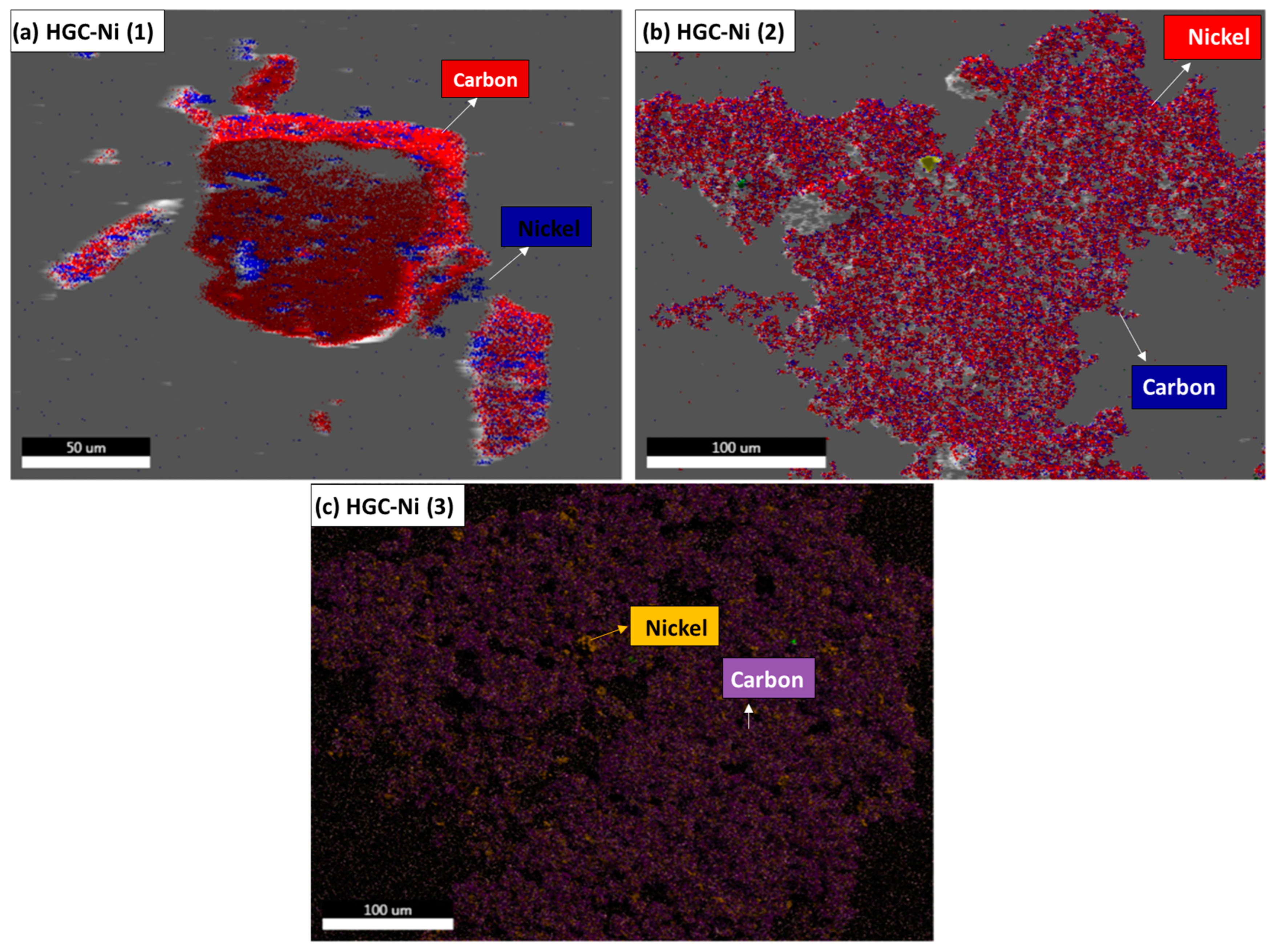
The concentrated regions due to carbon and nickel elements in the SEM-EDAX mapping are shown in Figure 2a–c for HGC-Ni (1), (2), and (3), respectively. The EDAX mapping seen in Figure 2a of HGC-Ni (1) showed an almost equal distribution of the red carbon zone and blue nickel zone in the two small particles, in parallel with the obtained EDAX results % C = 50.40% and % Ni = 46.74%. It is obvious from the Figure 2b mapping that the nickel red zone is dominating over the blue carbon zone. This result is in parallel with the EDAX result % Ni = 59.35% and % C = 8.43%. On the other hand, the purple carbon zone (% C = 50.33%) exceeded the orange nickel zone (Ni = 32.36%) in HGC-Ni (3); Figure 2c.

2.2.3. Powder X-ray Diffraction Analysis of the Nickel Nanocomposites

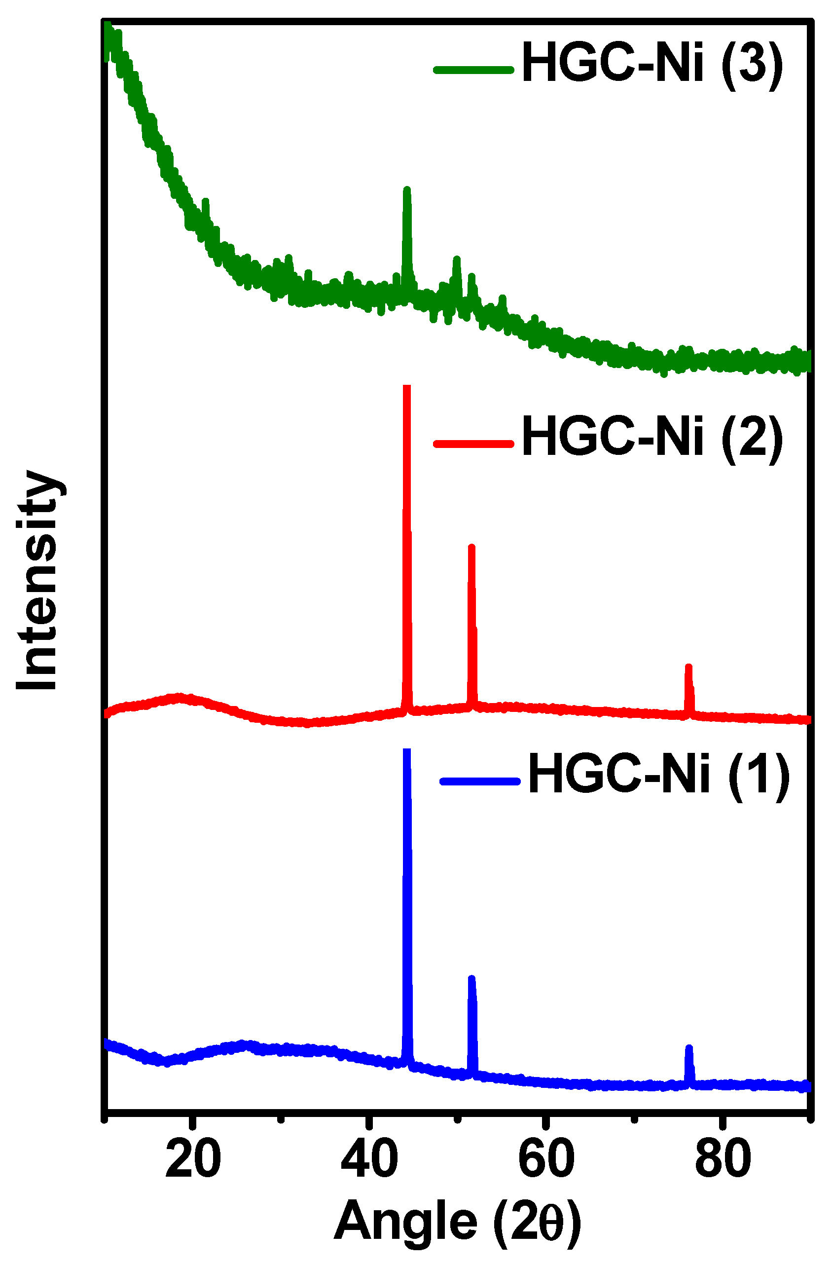
The crystalline nature of the nickel nanocomposites HGC-Ni (1), (2), and (3) were examined using the powder X-ray diffraction technique; Figure 3. The powder X-ray diffraction of samples HGC-Ni (1), (2), and (3) showed sharp, strong peaks at 44.5, 51.9, and 76.4, corresponding to the (111), (200), and (220) planes of Ni (JCPDS 04-004-6756) [26]. Crystal system: cubic; space group: Fm-3m; space group number: 225; a (Å): 3.5238; b (Å): 3.5238; c (Å): 3.5238; alpha (°): 90.0000; beta (°): 90.0000; gamma (°): 90.0000; volume of cell (106 pm3): 43.76. Additional peaks in the weak diffraction peaks appeared at 49.6 and 55.3 in the HGC-Ni (3) sample. They are attributed to the diffractions from the nickel nanocarbon particles, which were more evident than in the other samples HGC-Ni (1) and (2).

2.3. Catalytic Study

2.3.1. Determination of Catalytic Activity of HGC-Ni Nano-Catalyst for Hydrogenation of PNP and MO

The catalytic reduction reactions of PNP and MO pollutants by nano-catalysts HGC-Ni (1), (2), and (3) were followed by measuring the UV–visible absorption spectra of pollutants in the presence of NaBH4 and nano-catalysts in water, in the range of 200–600 nm at different time intervals. Sodium borohydride was used as the reducing agent that the hydrogen molecules needed for the reduction by the nano-catalysts. It was noted that the reduction reaction proceeded very fast compared to when not using a nano-catalyst [27,28].
The UV–visible spectrum of PNP in the presence of nano-catalysts showed λmax peaks at 227 nm and 317 nm. But when NaBH4 was added, the λmax peak at 317 nm was shifted to 400 nm due to the formation of the para-nitrophenolate anion. As the reduction reaction proceeded, the peak at 400 nm decreased, and the two new peaks at λmax 235 nm and 300 nm increased in intensity due to the formation of a less toxic reaction product, p-aminophenol (PAP). Figure 4a–f refers to the reaction progress by the UV–visible absorption and the first-order kinetic plot for a representative cycle number 3 for each of the nano-catalysts (1), (2), and (3), respectively [29].
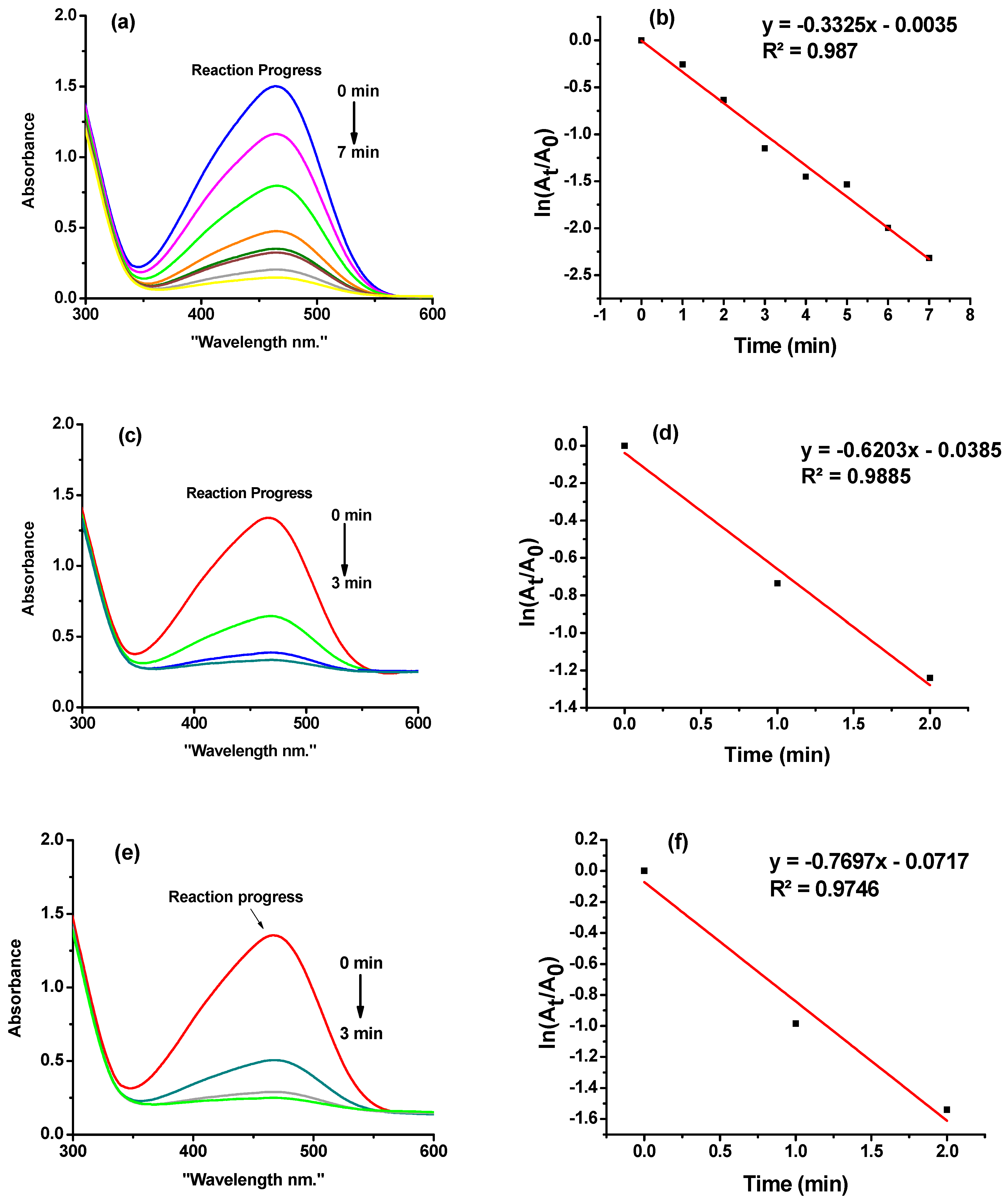
Similarly, the UV–visible spectrum of MO in the presence of nano-catalysts HGC-Ni (1), (2), and (3) showed peaks with the λmax equal to 272 nm and 467 nm. The addition of NaBH4 to the mixture did not affect the UV–visible spectrum. But when the reduction reaction proceeded, the peaks at 467 nm decreased, and a new peak at 253 nm increased dramatically due to the formation of N,N-dimethyl-p-phenylenediamine and sulfanilic acid products. Figure 5a–f refers to the reaction progress by UV–visible absorption spectroscopy and the first-order kinetic plots for representative cycle 6 for nano-catalysts (1), (2), and (3), respectively.
The reduction reaction was monitored by measuring the UV–visible spectra till the complete disappearance of the added pollutant MO molecules (100% conversion); this was counted as cycle number 1. Then, a new cycle was repeated by adding only the same amount of pollutant, and so on, till the complete poisoning of the nano-catalysts. The achieved number of cycles obtained for the reduction of PNP were 7.6, 4.6, and 17.9 cycles for nano-catalysts (1), (2), and (3), respectively; Table 1 and Table S1, Figure S2. The total number of reduction cycles was 13.9, 18.8, and 22.8 cycles, respectively; Table 2 and Table S2, Figure S3. This indicated that nano-catalyst (3), which contained sulfur, achieved the greatest number of cycles for the reduction of PNP and MO.
The catalytic efficiency was also evaluated by the determination of the average first-order rate constant values, which are listed in Table 1 for PNP and Table 2 for MO. The absorption of the peak at λmax 400 nm decreased with time for PNP until reaching zero, and the duration of the third cycle was 10, 12, and 5 min for nano-catalysts (1), (2), and (3), respectively; Figure 4. Meanwhile, for the MO reduction, the absorbance at 467 nm decreased in value with time till reaching a value of zero. The duration of the third cycle was 7, 3, and 3 min for nano-catalysts (1), (2), and (3); Figure 5. The first-order rate constants were calculated from the slopes of the plots of ln(A/A0) versus time t (min); Figure 4 and Figure 5 for PNP and MO, respectively. Where A is the absorbance at time t at λmax 400 nm (PNP) and 467 nm (MO), and A0 is the absorbance at time zero. The rate constants were calculated for all the completed cycles (Tables S1 and S2, Figures S2 and S3) for PNP and MO, and the average value for each nano-catalyst was computed and presented in Table 1 for PNP and Table 2 for MO. It was found that the average rate constants followed this increasing order for the reduction of PNP: 0.104, 0.141, and 0.173 min−1 for nano-catalysts (2), (1), and (3), respectively. Also, the average rate constants followed this increasing order with respect to MO: 0.363, 0.365, and 0.404 min−1 for nano-catalysts (3), (2), and (1), respectively.
The catalytic activity for the reduction of pollutants was also compared in terms of the computed turnover number (TON) and turnover frequency (TOF), Table 1, Table 2, Tables S1 and S2. The TON for the reduction of PNP increased for the catalysts according to (2) < (1) < (3); 0.641, 1.068, and 2.410 mg PNP/mg catalyst, respectively. Meanwhile, the TON order for the catalysts with respect to the reduction of MO was (1) < (2) < (3); 4.448, 5.693, and 7.302 mg MO/mg catalyst, respectively. Thus, the nickel nano-catalyst (3) provided the highest conversion yield compared to the other two nano-catalysts for both the PNP and MO reduction. However, the turnover frequency (TOF) for the reduction of p-nitrophenol PNP increased in the following order for the catalysts (3), (2), and (1): 0.0074, 0.0094, and 0.0098 (mg PNP/mg catalyst/min), respectively. Meanwhile, the TOF of the reduction of methyl orange (MO) increased in the following order for the catalysts (3), (1), and (2): 0.0332, 0.0347, and 0.0385 (mg MO/mg catalyst/min), respectively. Thus, nickel nano-catalysts (1) and (2) provided the highest performance compared to the other nano-catalysts for the reduction of PNP and MO, respectively.
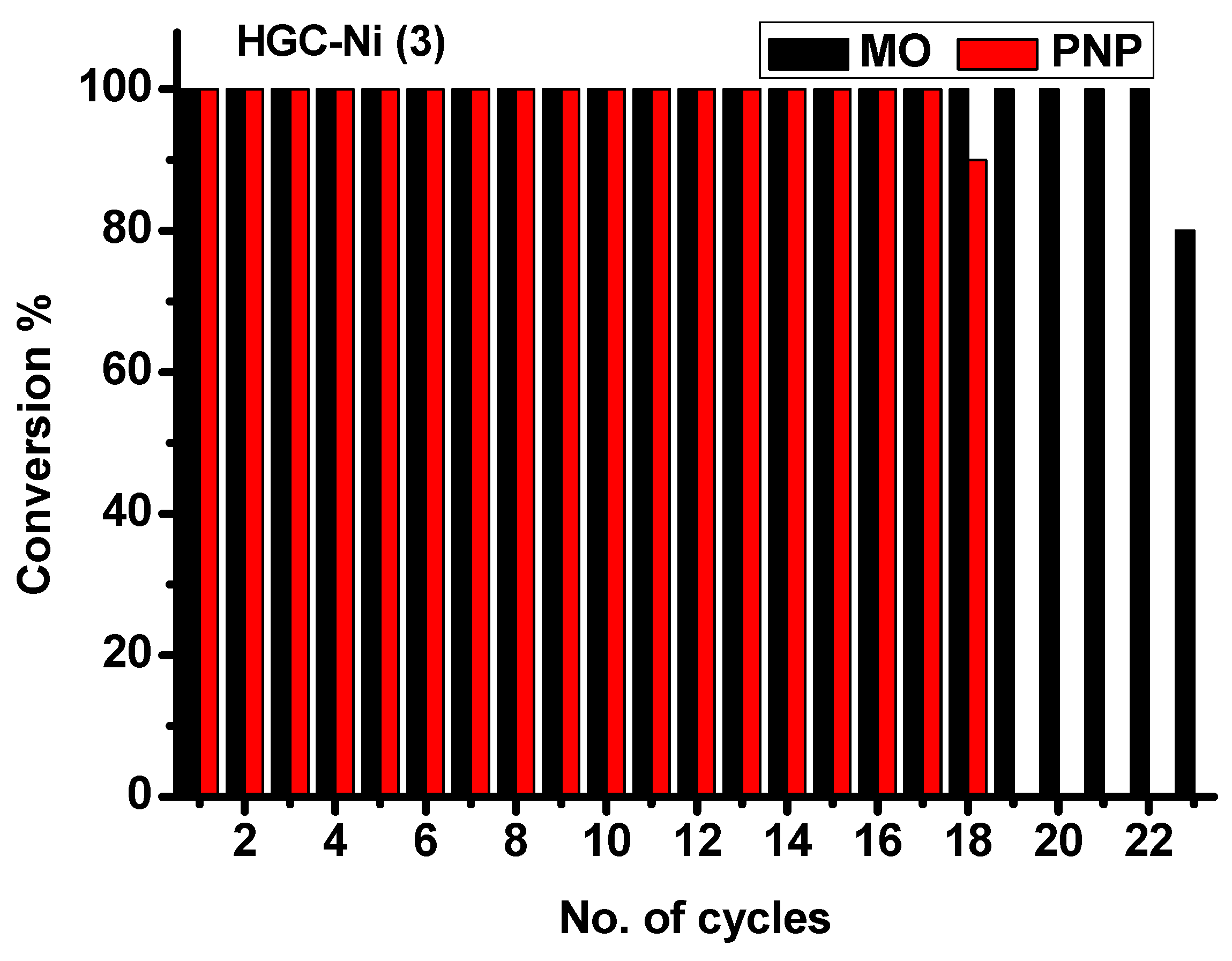
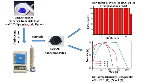
The number of cycles for the degradation of MO and PNP were compared for nano-catalyst HGC-Ni (3) in Figure 6. The number of cycles was 23 for MO, while it was smaller for PNP, with 18 cycles.

2.3.2. Batch Catalytic Experiment: Chemical, Photochemical, and Regeneration

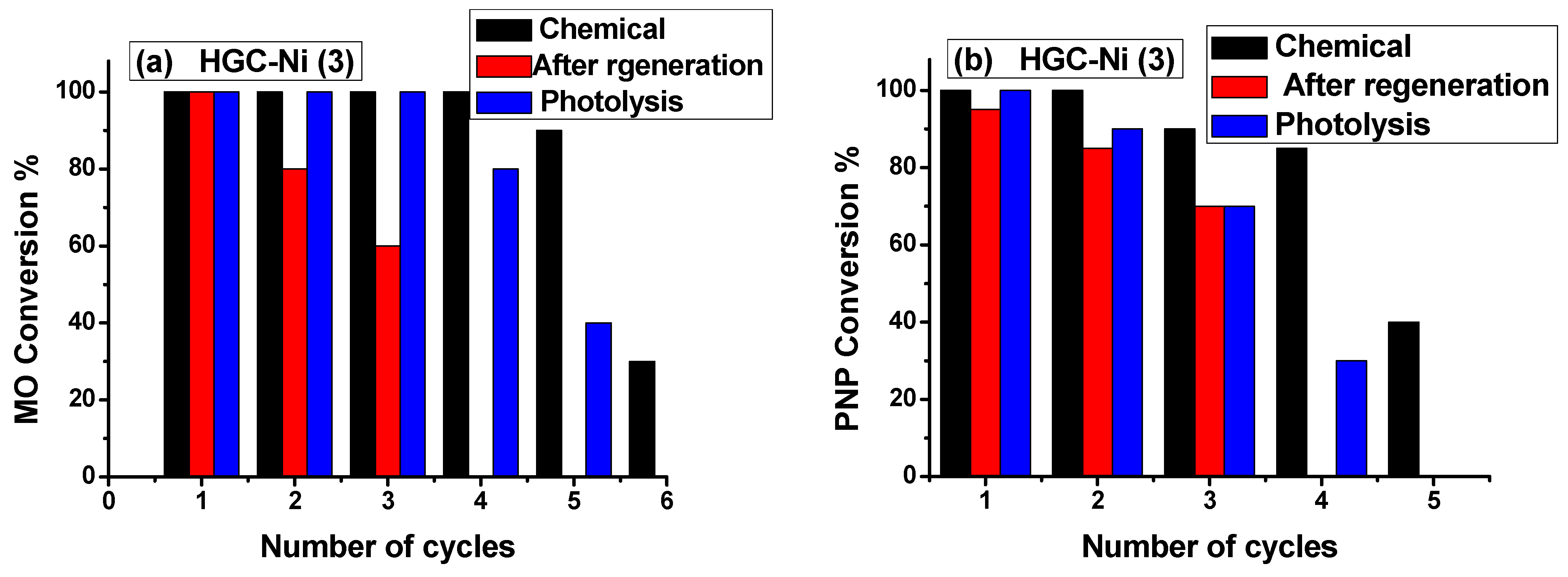
In a typical batch experiment, 1 mg of catalyst HGC-Ni (3) in water (10 mL) was mixed with 1 mg of MO or 0.5 mg of PNP. The progress of the reaction was monitored at different times (min) in the absence of light (chemical catalysis) or irradiated with a visible light lamp having 30 watts of power (photolysis). Then, 1 mg MO or 0.5 mg was additionally added in each new cycle. The total NaBH4 consumed was 10 mg. In chemical catalysis, the total number of achieved cycles for MO was six. The TON was 5.5 mg of MO/mg catalyst, and the total time was 205 min; the TOF was 0.0268 (mg MO/mg catalyst/min). The total number of achieved cycles for PNP was five and the total time was 300 min. The TON was 2.08 mg of PNP/mg catalyst; The TOF was 0.007 (mg MO/mg catalyst/min). After the end of the experiment, the catalyst was regenerated by washing with water and ethanol several times and then reused in a new experiment. The number of cycles achieved after regeneration was three for each of MO and PNP, with a minor decrease in efficiency and a longer time of cycle (Figure 7).
A photolysis experiment was performed using the catalyst HGC-Ni (3). The total number of cycles for MO was five, and the time was 225 min. The TON was 4.2 mg of MO/mg catalyst, and the TOF was 0.0186 (mg MO/mg catalyst/min). Meanwhile, the number of cycles for PNP was four, and the total time of the experiment was 320 min. The TON was 1.45 mg of PNP/mg catalyst, and the TOF was 0.0045 (mg PNP/mg catalyst/min). Thus, light exposure has no effect on the reduction reaction since it did not provide improvement in the % conversion; Figure 7. It was difficult to compare the catalyst HGC-Ni with the Degusa P25 catalyst because of the difference in the used experimental condition.

2.3.3. Mechanism of Hydrogenation of PNP and MO by HGC-Ni Catalysts

The reduction experiment in an aqueous solution depends on self-generated hydrogen from the hydrolysis of sodium borohydride; Scheme 1A. However, we have noted in our study the extensive generation of hydrogen bubbles during the reduction reaction of PNP or MO in an aqueous solution containing sodium borohydride and a catalyst compared to an aqueous solution of sodium borohydride without a catalyst. Thus, the catalyst HGC-Ni improved the hydrogen generation in the presence of sodium borohydride (probably through a hydrogen mediator such as Ni2B) [30]. Nickel hydride (Ni-H) can be produced upon cleavage of H2 (g) by HGC-Ni and forming HGC-Ni-H; Scheme 1A. Also, during the reaction, p-nitrophenol or methyl orange were adsorbed onto nano-catalysts aided by π-π interactions between their aromatic rings and the aromatic rings of graphitic carbon layers present in HGC-Ni [25]. The formed nickel hydride provided the necessary hydrogen atoms for the reduction reaction. In the case of p-nitrophenol PNP, the -NO2 group was reduced by the addition of two H atoms, followed by the loss of H2O molecules and the formation of a nitroso group -N=O. Then, the other two H atoms were added to the nitroso group, followed by the formation of the hydroxylamine group. Finally, hydroxylamine was reduced to the amino group by the addition of two H atoms and the loss of water molecules. Then, p-aminophenol PAP was obtained; Scheme 1B [20]. On the other hand, in the case of methyl orange reduction, HGC-Ni-H provided two H atoms to reduce the azo group -N=N- to hydrazo group -NH-NH-; then, it was followed by another two H atoms to reduce the hydrazo group and cleaved it into two amino groups, resulting in the formation of N,N-dimethyl-p-phenylenediamine and sulfanilic acid molecules; Scheme 1C [31].
In conclusion, it is of great importance to convert the highly cancerogenic p-nitrophenol [32] to p-aminophenol PAP, which is considered safe to use as cosmetic ingredients in hair dyes [33]. Additionally, PAP is a useful intermediate for the fabrication of antipyretic and analgesic drugs [12,32]. Also, methyl orange dye is very toxic and carcinogenic and limits the penetration of sunlight [34]. The present study demonstrated the efficient catalytic cleavage of the azo group of MO. This caused the removal of color from polluted water and produced simpler N,N-dimethyl-p-phenylenediamine and sulfanilic acid molecules, which are easier to degrade or can be used as intermediates in organic synthesis.
The catalytic activity of the HGC-Ni catalyst was compared with others reported in the literature. The first-order rate constant (min−1) of HGC-Ni (3), with respect to the reduction of PNP, was 0.173 min−1. It was less than that of the nano Ni/carbon black catalyst (Ni 0.22/CB (0.597 min−1) [20] but higher than that of Ag/ZnO-Chitosan (0.169 min−1) [35]. Meanwhile, the first-order rate constant (min−1) for the reduction of MO by HGC-Ni (1) was 0.404 min−1, which was higher than 0.0335 (min−1) for the solid substrates decorated with Ag nanostructures [34] and Ag/ZnO-Chitosan (0.0998 min−1) [35].

2.4. Electrochemical Properties of HGC-Ni Catalysts

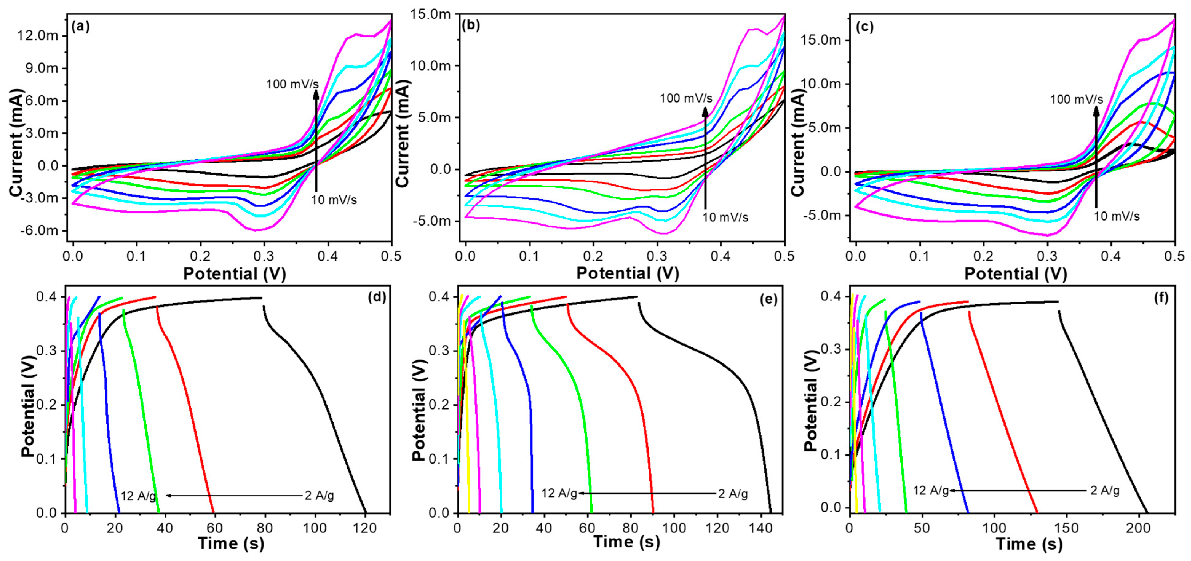
In the realm of nickel–graphitic carbon (HGC-Ni) nanocomposites tailored for electrode applications, detailed electrochemical analyses, specifically via cyclic voltammetry (CV) (Figure 8a and Figure 9a–c)) and galvanostatic charge–discharge (GCD) studies (Figure 8b and Figure 9d–f), have been pivotal in elucidating their capacitive behaviors. Conducted within a rigorously controlled KOH electrolyte environment, these tests have allowed for a nuanced understanding of the electrode capabilities. The CV assessments have consistently highlighted the presence of distinct redox activity, indicative of the electrodes’ pseudo-capacitive properties, particularly evidenced by the discernible redox peaks, which are a manifestation of the transition between nickel and nickel hydroxides. Such activity is crucial for applications necessitating quick energy exchanges [36,37,38].
The rate-dependent investigation of these electrodes revealed a linear relationship in the redox current response, underscoring a diffusion-dominated mechanism at play. Notably, the modified Ni-GC electrodes, especially with a GC-Ni (3) enhancement, showed remarkable performance (Figure 8c). This was evidenced by their larger CV curve areas and notably higher specific capacitance, which was further substantiated by GCD profiling, as shown in the respective figures (Figure 9a–f).
A detailed examination through GCD testing underscored the exceptional charge retention ability of the Ni-GC electrode (Figure 9a–f), surpassing its counterparts significantly at a current density of 2 to 12 (A/g). The HGC-Ni (1) electrode delivered capacitance values of 210.0, 147.0, 105.0, 94.0, 70.0, and 50.0 (F/g) at the current densities of 2, 2.5, 3, 5, 7, and 10 (A/g). The HGC-Ni (2) electrode delivered capacitance values of 305.0, 250.0, 180.0, 168.0, 157.0, 112.0, and 75.0 (F/g) at the current densities of 2, 2.5, 3, 5, 7, 10, and 12 (A/g). Meanwhile, the HGC-Ni (3) electrode delivered capacitance values of 320.0, 300.0, 247.0, 187.0, 175.0, 125.0, and 60 (F/g) at the current densities of 2, 2.5, 3, 5, 7, 10, and 12 (A/g); Figure 8c. In a comparative analysis, this particular configuration has also maintained its superiority in charge-storage capacity across various current densities.
Overall, the findings advocate for the strategic integration of carbon into the Ni-GC matrix, as this modification has been demonstrated to effectively amplify the electrochemical efficiency of the resulting electrodes [36,37,38]. The optimal level of carbon in the Ni-GC electrodes emerges as a promising composition, offering a balance that enhances capacitance while maintaining robust rate performance and durability (Figure 10). This advancement marks a significant stride in the advancement of energy-storage systems.

3. Experimental Section

3.1. Equipment

A field emission scanning electron microscope (FE-SEM, JEOL JSM-76700F) (JEOL, Tokyo, Japan), equipped with an EDX system (elemental mapping), was used to study the morphologies and elemental analyses of the synthesized samples. Powder X-ray diffraction (PXRD) measurements were carried out using the PAN analytical X’Pert PRO MP X-ray diffractometer, consisting of a focusing elliptical mirror and a fast-high resolution detector (PIXCEL) with a radiation wavelength of 0.15418 nm. The electrochemistry equipment used was a Metrohm autolab electrochemical workstation.

3.2. Preparation of Metal Complexes

3.2.1. Ni(2,2′-bipyridine)Cl2.H2O

The two solutions, metal salt NiCl2.6H2O (10 mmol) in 25 mL of ethanol and the ligand 2,2′-bipyridine (5 mmol) in 25 mL ethanol, were vigorously mixed. The resulting mixture was refluxed for 6 h [39]. The obtained precipitate was collected by filtration, washed with cold ethanol, and oven-dried to give 2.25 mmol of the light green powder Ni(2,2′-bipyridine)Cl2.H2O complex (45% yield).

3.2.2. [Ni(tpht)(2,2′-bipy)].4H2O

An aqueous solution was prepared by mixing 5 mmol of Ni(NO3)2.6H2O in 90 mL of distilled water with 5 mmol of 2,2′-bipyridine ligand in 30 mL of ethanol [40]. To this mixture was added 5 mmol of sodium terephthalate Na2tpht in 50 mL of water. The reaction mixture was stirred for 3 h. The precipitate formed was collected by filtration and oven-dried to give the light blue powder (3 mmol, 60% yield).

3.2.3. [Ni(phen)2(H2O)2]SO4.5.6H2O

NiSO4.7H2O (5 mmol) was dissolved in 30 mL of water, and then phenanthroline powder (5 mmol) was added with continuous stirring. The mixture was slowly heated to 50 °C for one hour, then left stirred at room temperature for 2 h [41]. A bluish powder was obtained after 1 day, and the mixture was then filtered. The product was collected, washed with water, and dried, giving 2.8 mmol (56% yield).

3.3. Preparation of Hierarchically Graphitic Carbon Containing Nickel Nanoparticles HGC-Ni

3.3.1. Preparation HGC-Ni (1)

The [Ni(2,2′-bipyridine)Cl2].H2O complex (1 gm) and anthracene (1 gm) were mixed together in a porcelain crucible, then placed in a nitrogen gas furnace and heated for 2 h at 300 °C, followed by heating at 850 °C for 15 h. A total of 0.323 gm of black powder was then obtained after slow cooling to room temperature.

3.3.2. Preparation of HGC-Ni (2)

The [Ni(tpht)(2,2′-bipy)].4H2O complex (1 gm) and anthracene (1 gm) were mixed and heated similarly as above. A total of 0.130 gm of black powder was obtained.

3.3.3. Preparation of HGC-Ni (3)

The [Ni(phen)2(H2O)2]SO4.5.6H2O complex (1 gm) and pyrene (1 gm) were mixed and heated similarly as above. A total of 0.144 gm of black powder was obtained.
The preparation of complexes and their pyrolysis procedures are illustrated in Figure 11.

3.4. Catalysis Experiment

3.4.1. Catalytic Reduction of p-Nitrophenol (P-NP)

The PNP pollutant solution was utilized as the model for the catalytic reduction reaction in the presence of NaBH4 as a reducing agent in order to assess the catalytic performance of the prepared nano-catalysts. In a typical experiment of catalytic degradation of p-nitrophenol (PNP), an aqueous suspension of nano-catalysts (1 mg catalyst/1 mL water) was treated ultrasonically for 5 min. Then, 0.2 mL of the previous solution, 2.5 mL of distilled water, 0.1 mL of (7 mg PNP/25 mL water) p-nitrophenol, and 4 mg of NaBH4 were mixed in a quartz cuvette. This reduction reaction can be monitored precisely through UV–visible spectroscopy by the change in absorbance at definite time intervals. For each new cycle, an additional 0.1 mL of PNP solution was added.

3.4.2. Catalytic Reduction of Methyl Orange (MO)

The nano-catalysts were tested for the degradation of hazardous organic dyes through catalytic reduction. Methyl orange (MO) was chosen as a model organic dye, with NaBH4 as a reducing agent. In a typical degradation process, an aqueous suspension of catalysts (1 mg catalyst/1 mL water) was ultrasonically treated. A total of 0.2 mL of the previous solution, 2.5 mL of distilled water, 0.05 mL of MO (32 mg MO/25 mL water), and 4 mg of NaBH4 were mixed in a quartz cuvette. The catalytic degradation process of MO was assessed by monitoring the change in intensity of the UV–visible absorption peak of MO at different times. The reduction is considered complete when the absorbance peak at λmax 464 nm decreases to almost zero. For each new cycle, an additional 0.05 mL of PNP solution was added.

3.4.3. Electrochemical Measurements and Calculation

We have developed electrodes by meticulously coating spherical Ni-GC nanoparticles onto a nickel substrate. The chosen composition for the slurry consisted of 10% polytetrafluoroethylene and 10% carbon black to ensure structural integrity and electrical conductivity, respectively, with the remainder being 80% of the active material for efficient electrochemical performance. These electrodes were then evaluated in a standard three-electrode cell configuration. Nickel foam served as the working electrode, providing a substantial three-dimensional area for the active material, thus enhancing the electroactive surface area. For consistency and accurate measurements, a AgCl/Ag (3M KCl) reference electrode and a platinum-plate counter electrode were utilized. To ascertain the specific capacitance, which is a critical performance metric for our electrodes, we applied the following relation: C = Idt/mdV. Here, ‘C’ signifies the specific capacitance in farads per gram (F/g), I is the current in (A) that was applied during the electrochemical process, ‘t’ (s) stands for the total time over which the discharge occurred, ‘m’ (g) represents the mass of the active material loaded on the current collector, and ‘dV’ refers to the potential window (V) over which the device was operated. This formula allows for a precise quantification of the energy-storage capacity of our electrodes.

4. Conclusions

The pyrolysis of [Ni(2,2′-bipyridine)Cl2].H2O, [Ni(tpht)(2,2′-bipy)].4H2O, and [Ni(phen)2(H2O)2]SO4.5.6H2O in the presence of a carbon source (pyrene or anthracene) produced novel hierarchical graphite containing nickel nanoparticles HGC-Ni (1), (2), and (3), respectively. The nanomaterials contained nickel (0) nanoparticles with diameter sizes ranging from 60 nm to 500 nm wrapped with graphitic carbon layers. All samples contained nickel and carbon. Additionally, chlorine, oxygen, and sulfur were present in HGC-Ni (1), HGC-Ni (2), and HGC-Ni (3), respectively, and originated from their precursor complexes. HGNi-GCs showed excellent catalytic activity for the reduction of PNP and MO. The highest turnover number (TON) for the reduction of p-nitrophenol (PNP) and MO was obtained for HGC-Ni (3) (2.410 mg of PNP/mg catalyst and 7.302 mg of MO/mg catalyst). HGNi-GC (3) had the highest number of cycles with respect to PNP (17.9 cycles), and also with respect to MO (22.8 cycles). The first-order rate constant (min−1) of HGC-Ni (3), with respect to the reduction of PNP, was 0.173 min−1. Meanwhile, the first-order rate constant (min−1) for the reduction of MO by HGC-Ni (1) was 0.404 min−1. The catalysts were regenerated efficiently for an additional three cycles.
Recent research has revealed that the nickel–graphitic carbon composite, known as HGNi-GC, demonstrated exceptional electrochemical capacitance properties. When tested at a current density of 2 A/g, this material registered an impressive specific capacitance of 320.0 F/g. Its durability was further underscored by its ability to retain about 86.8% of its original capacitance, even after 2500 charge–discharge cycles. These attributes position the Ni-GC composite as a notable candidate in the realm of energy storage, offering both high capacitive efficiency and longevity, which are crucial for various technological applications.

Supplementary Materials

The following supporting information can be downloaded at: https://www.mdpi.com/article/10.3390/catal14030181/s1, Figure S1: EDAX of HGC-Ni (1), HGC-Ni (2), and HGC-Ni (3) nanocomposites. Figure S2: Progress of UV–vis spectra at different cycles for reduction of 4-nitrophenol by HGC-Ni (1), (2), and (3) nano-catalysts. Figure S3: Progress of UV–vis spectra at different cycles for reduction of MO by HGC-Ni (1), (2), and (3) nano-catalysts. Table S1: Catalytic reduction of the PNP by HGC-Ni (1), (2), and (3) nano-catalysts. Table S2: Catalytic reduction of the MO by HGC-Ni (1), (2), and (3) nano-catalysts.

Author Contributions

Conceptualization, H.H.H. and N.P.; methodology, H.H.H., W.A.A., D.E.A.-H., S.A.A. and T.P.; software, H.H.H.; validation, H.H.H.; investigation, D.E.A.-H., W.A.A., T.P. and N.P.; resources, H.H.H.; writing—original draft preparation, H.H.H. and S.A.A.; writing—review and editing, H.H.H., N.P. and S.A.A.; supervision, H.H.H.; project administration, H.H.H.; funding acquisition, H.H.H. All authors have read and agreed to the published version of the manuscript.

Funding

This work was supported by the Deanship of Scientific Research, vice Presidency for Graduate Studies and Scientific Research, King Faisal University, Saudi Arabia [Grant No. 3673].

Data Availability Statement

All data are available in the main text or the Supplementary Materials.

Conflicts of Interest

The authors declare that they have no known competing financial interests or personal relationships that could have appeared to influence the work reported in this paper.

References

  1. Karakas, K.; Celebioglu, A.; Celebi, M.; Uyar, T.; Zahmakiran, M. Nickel nanoparticles decorated on electrospun polycaprolactone/chitosan nanofibers as flexible, highly active and reusable nanocatalyst in the reduction of nitrophenols under mild conditions. Appl. Catal. B Environ. 2017, 203, 549–562. [Google Scholar] [CrossRef]
  2. Velusamy, S.; Roy, A.; Mariam, E.; Krishnamurthy, S.; Sundaram, S.; Mallick, T.K. Effectual visible light photocatalytic reduction of para-nitro phenol using reduced graphene oxide and ZnO composite. Sci. Rep. 2023, 13, 9521. [Google Scholar] [CrossRef]
  3. Emmanuel, S.S.; Adesibikan, A.A.; Opatola, E.A.; Olawoyin, C.O. A pragmatic review on photocatalytic degradation of methyl orange dye pollutant using greenly biofunctionalized nanometallic materials: A focus on aquatic body. Appl. Organomet. Chem. 2023, 37, e7108. [Google Scholar] [CrossRef]
  4. Kishor, R.; Purchase, D.; Dattatraya, G.; Ganesh, R.; Fernando, L.; Ferreira, R.; Bilal, M.; Chandra, R.; Naresh, R. Ecotoxicological and health concerns of persistent coloring pollutants of textile industry wastewater and treatment approaches for environmental safety. J. Environ. Chem. Eng. 2021, 9, 105012. [Google Scholar] [CrossRef]
  5. Khan, I.; Saeed, K.; Ali, N.; Khan, I.; Zhang, B.; Sadiq, M. Heterogeneous photodegradation of industrial dyes: An insight to different mechanisms and rate affecting parameters. J. Environ. Chem. Eng. 2020, 8, 104364. [Google Scholar] [CrossRef]
  6. Sam, S.P.; Tan, H.T.; Sudesh, K.; Adnan, R.; Ting, A.S.Y.; Ng, S.L. Phenol and p-nitrophenol biodegradations by acclimated activated sludge: Influence of operational conditions on biodegradation kinetics and responding microbial communities. J. Environ. Chem. Eng. 2021, 9, 105420. [Google Scholar] [CrossRef]
  7. Nekoeinia, M.; Yousefinejad, S.; Hasanpour, F.; Dezaki, M.Y. Highly efficient catalytic degradation of p-nitrophenol by Mn3O4.CuO nanocomposite as a heterogeneous fenton-like catalyst. J. Exp. Nanosci. 2020, 15, 322–336. [Google Scholar] [CrossRef]
  8. Wang, X.; Zhao, J.; Song, C.; Shi, X.; Du, H. An Eco-Friendly Iron Cathode Electro-Fenton System Coupled with a pH-Regulation Electrolysis Cell for p-Nitrophenol Degradation. Front. Chem. 2022, 9, 837761. [Google Scholar] [CrossRef] [PubMed]
  9. Jiang, P.; Zhou, J.; Zhang, A.; Zhong, Y. Electrochemical degradation of p-nitrophenol with different processes. J. Environ. Sci. 2010, 22, 500–506. [Google Scholar] [CrossRef]
  10. Wu, Z.; Yuan, X.; Zhong, H.; Wang, H.; Zeng, G.; Chen, X.; Wang, H.; Zhang, L.; Shao, J. Enhanced adsorptive removal of p-nitrophenol from water by aluminum metal-organic framework/reduced graphene oxide composite. Sci. Rep. 2016, 6, 25638. [Google Scholar] [CrossRef]
  11. Kumar, S.; Singh, S.; Srivastava, V.C. Electro-oxidation of nitrophenol by ruthenium oxide coated titanium electrode: Parametric, kinetic and mechanistic study. Chem. Eng. J. 2015, 263, 135. [Google Scholar] [CrossRef]
  12. Zhao, P.; Feng, X.; Huang, D.; Yang, G.; Astruc, D. Basic concepts and recent advances in nitrophenol reduction by gold- and other transition metal nanoparticles. Coord. Chem. Rev. 2015, 287, 114. [Google Scholar] [CrossRef]
  13. Khan, A.U.; Zahoor, M.; Rehman, M.U.; Shah, A.B.; Zekker, I.; Khan, F.A.; Ullah, R.; Albdrani, G.M.; Bayram, R.; Mohamed, H.R.H. Biological Mineralization of Methyl Orange by Pseudomonas aeruginosa. J. Water 2022, 14, 1551. [Google Scholar] [CrossRef]
  14. Ahmed, H.M.; Fawzy, M.E.; Nassar, H.F. Effective Chemical Coagulation Treatment Process for Cationic and Anionic Dyes Degradation, Egypt. J. Chem. 2022, 65, 301–310. [Google Scholar] [CrossRef]
  15. He, W.; Liu, Y.; Ye, J.; Wang, G. Electrochemical degradation of azo dye methyl orange by anodic oxidation on Ti4O7 electrodes. J. Mater. Sci. Mater. Electron. 2018, 29, 14065–14072. [Google Scholar] [CrossRef]
  16. Tran, V.A.; Kadam, A.N.; Lee, S.W. Adsorption-assisted photocatalytic degradation of methyl orange dye by zeolite-imidazole-framework-derived nanoparticles. J. Alloys Compd. 2020, 835, 155414. [Google Scholar] [CrossRef]
  17. Rajput, N.L.; Mughal, M.A.; Balouch, A.; Khan, K.M.; Tunio, S.A.; Kanwal; Sohu, S. Effective photocatalytic methylene orange dye degradation ability in coloured textile contaminated water by highly efficient catalyst Schiff-based resin-encapsulated supported on TiO2@SiO2 metal oxide nanoparticles. Int. J. Environ. Anal. Chem. 2022, 102, 3561–3575. [Google Scholar] [CrossRef]
  18. Xingu-Contreras, E.; García-Rosales, G.; García-Sosa, I.; Cabral-Prieto, A. Degradation of methyl orange using iron nanoparticles with/without support at different conditions. Microporous Mesoporous Mater. 2020, 292, 109782. [Google Scholar] [CrossRef]
  19. Khan, S.A.; Bakhsh, E.M.; Akhtar, K.; Khan, S.B. A template of cellulose acetate polymer-ZnAl/C layered double hydroxide composite fabricated with Ni NPs: Applications in the hydrogenation of nitrophenols and dyes degradation. Spectrochim. Acta A Mol. Biomol. Spectrosc. 2020, 241, 118671. [Google Scholar] [CrossRef]
  20. Xia, J.; He, G.; Zhang, L.; Sun, X.; Wang, X. Hydrogenation of nitrophenols catalyzed by carbon black-supported nickel nanoparticles under mild conditions. Appl. Catal. B 2016, 180, 408–415. [Google Scholar] [CrossRef]
  21. Parveen, N.; Ansari, M.O.; Ansari, S.A.; Kumar, P. Nanostructured titanium nitride and its composites as high-performance supercapacitor electrode material. J. Nanomater. 2023, 13, 105. [Google Scholar] [CrossRef] [PubMed]
  22. Parveen, N.; Alsulaim, G.M.; Alsharif, S.A.; Almutairi, H.H.; Alali, H.A.; Ansari, S.A.; Ahmad, M.M. Renewable biopolymer-derived carbon–nickel oxide nanocomposite as an emerging electrode material for energy storage applications. J. Sci. Adv. Mater. Dev. 2023, 8, 100591. [Google Scholar] [CrossRef]
  23. Al-Abawi, B.T.; Parveen, N.; Ansari, S.A. Controllable synthesis of sphere-shaped interconnected interlinked binder-free nickel sulfide@nickel foam for high-performance supercapacitor applications. Sci. Rep. 2022, 12, 14413. [Google Scholar] [CrossRef] [PubMed]
  24. Hammud, H.H.; Karnati, R.K.; Alotaibi, N.; Hussain, S.G.; Prakasam, T. Cobalt–carbon silica nanoparticles for uptake of cationic and anionic dye from polluted water. Molecules 2021, 26, 7489. [Google Scholar] [CrossRef]
  25. Alramadhan, S.A.; Hammud, H.H. Graphene Nickel Silica Supported Nanocomposites, Application in Water Treatment. J. Appl. Nanosci. 2020, 11, 273–291. [Google Scholar] [CrossRef]
  26. Ng, S.C.; Brockhouse, B.N.; Hallman, E.D. Characterization of large alloy single crystals by neutron diffraction. Mater. Res. Bull. 1967, 2, 69–73. [Google Scholar] [CrossRef]
  27. Hammud, H.H.; Traboulsi, H.; Karnati, R.K.; Hussain, S.G.; Bakir, E. Hierarchical Graphitic Carbon-Encapsulating Cobalt Nanoparticles for Catalytic Hydrogenation of 2,4-Dinitrophenol. Catalysts 2022, 12, 39. [Google Scholar] [CrossRef]
  28. Bukhamsin, H.A.; Hammud, H.H.; Awada, C.; Prakasam, T. Catalytic Reductive Degradation of 4-Nitrophenol and Methyl orange by Novel Cobalt Oxide Nanocomposites. Catalysts 2024, 14, 89. [Google Scholar] [CrossRef]
  29. Hammud, H.H.; Traboulsi, H.; Karnati, R.K.; Bakir, E. Photodegradation of Congo Red by Modified P25-Titanium Dioxide with Cobalt-Carbon Supported on SiO2 Matrix, DFT Studies of Chemical Reactivity. Catalysts 2022, 12, 248. [Google Scholar] [CrossRef]
  30. Delmas, J.; Laversenne, L.; Rougeaux, I.; Capron, P.; Garron, A.; Bennici, S.; Swierczynski, D.; Auroux, A. Improved hydrogen storage capacity through hydrolysis of solid NaBH4 catalysed with cobalt boride. Int. J. Hydrog. Energy 2011, 36, 2145–2153. [Google Scholar] [CrossRef]
  31. Dorraj, M.; Sadjadi, S.; Heravi, M.M. Pd on poly(1-vinylimidazole) decorated magnetic S-doped grafitic carbon nitride: An efficient catalyst for catalytic reduction of organic dyes. Sci. Rep. 2020, 10, 13440. [Google Scholar] [CrossRef]
  32. Tchieno, F.M.M.; Tonle, I.K. p-Nitrophenol determination and remediation: An overview. Rev. Anal. Chem. 2018, 37, 20170019. [Google Scholar] [CrossRef]
  33. Elder, R.L. Final report on the safety assessment of p-aminophenol, m-aminophenol, and o-aminophenol. J. Am. Coll. Toxicol. 1988, 7, 279–333. [Google Scholar]
  34. Sakir, M.; Onses, M.S. Solid substrates decorated with Ag nanostructures for the catalytic degradation of methyl orange. Results Phys. 2019, 12, 1133–1141. [Google Scholar] [CrossRef]
  35. Khan, S.B.; Ismail, M.; Bakhsh, E.M.; Asiri, A.M. Design of simple and efficient metal nanoparticles templated on ZnO-chitosan coated textile cotton towards the catalytic reduction of organic pollutants. J. Ind. Text. 2022, 51 (Suppl. S1), 1703S–1728S. [Google Scholar] [CrossRef]
  36. Ansari, M.Z.; Seo, K.M.; Kim, S.H.; Ansari, S.A. Critical aspects of various techniques for synthesizing metal oxides and fabricating their composite-based supercapacitor electrodes: A review. J. Nanomater. 2022, 12, 1873. [Google Scholar] [CrossRef] [PubMed]
  37. Abdelbasir, S.M.; Attia, S.Y.; Mohamed, S.G.; El-Hout, S.I. Waste-derived Ni/C composite material for supercapacitor applications. J. Energy Storage 2023, 65, 107332. [Google Scholar] [CrossRef]
  38. Jiang, X.Y.; Deng, S.; Liu, J.; Qi, N.; Chen, Z. Metal–organic framework derived NiO/Ni@C composites as electrode materials with excellent electrochemical performance for supercapacitors. J. Energy Storage 2021, 37, 102426. [Google Scholar] [CrossRef]
  39. Brewer, B.; Brooks, N.R.; Abdul-Halim, S.; Sykes, A.G. Differential metathesis reactions of 2,2’-bipyridine and 1,10-phenanthroline complexes of cobalt(II) and nickel(II): Cocrystallization of ionization isomers {[cis-Ni(phen)2(H2O)2][cis-Ni(phen)2(H2O)Cl]}(PF6)3·4.5H2O, and a synthetic route to asymmetric t. J. Chem. Crystallogr. 2003, 33, 651–662. [Google Scholar] [CrossRef]
  40. Rogan, J.; Poleti, D.; Karanović, L.; Bogdanović, G.; Biré, A.S.-D.; Petrović, D.M.; Co, M.L. Ni(II) and Cu(II) complexes containing terephthalato ligands. Crystal structures of diaqua(2,2′-dipyridylamine)(terephthalato)metal(II) trihydrates (metal = cobalt or nickel). J. Polyhedron. 2000, 19, 1415–1421. [Google Scholar] [CrossRef]
  41. Zhu, L.; Zhang, L.H.; Liu, B.Y.; An, Z. Crystal structure of diaquabis(1,10-phenanthroline)nickel(II) sulfate hydrate (1:5.6), [Ni(H2O)2(C12H8N2)2][SO4]·5.6H2O. Z. Kristallogr. NCS 2006, 221, 451–452. [Google Scholar] [CrossRef]
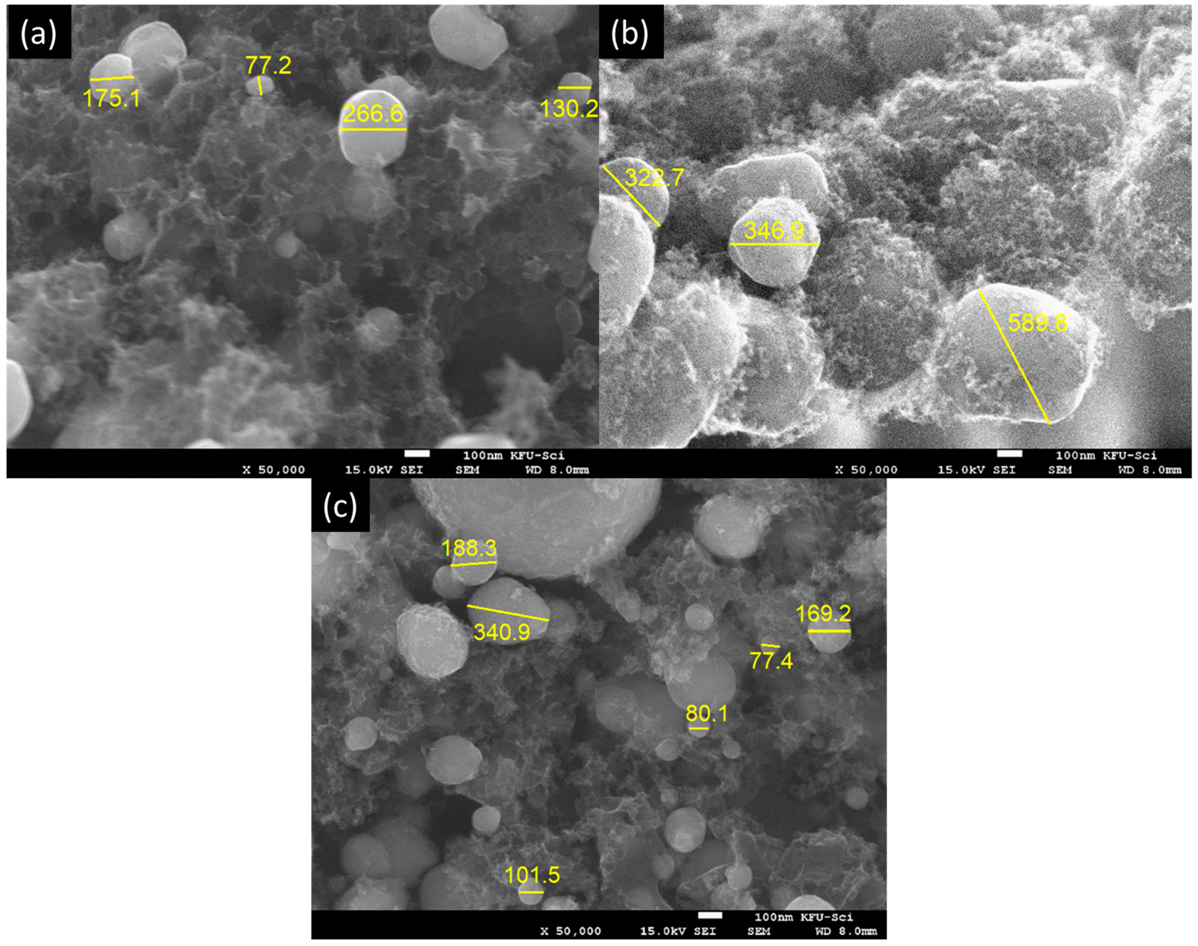
Figure 1. Scanning electron microscopy (SEM) figures for (a) HGC-Ni (1), (b) HGC-Ni (2), and (c) HGC-Ni (3).
Catalysts 14 00181 g001
Figure 2. SEM-EDAX mapping of (a) HGC-Ni (1), (b) HGC-Ni (2), and (c) HGC-Ni (3) showed carbon and nickel distributions.
Catalysts 14 00181 g002
Figure 3. Powder X-ray diffraction analyses of HGC-Ni (1), (2), and (3) showed peaks 44.5, 51.9, and 76.4, corresponding to the (111), (200), and (220) planes of Ni (JCPDS 04-004-6756).
Catalysts 14 00181 g003
Figure 4. Catalytic reduction activity: Progress of reaction by UV–visible spectroscopy and kinetic rate of reaction of PNP with NaBH4 at cycle (3) with (a,b) HGC-Ni (1), (c,d) HGC-Ni (2), and (e,f) HGC-Ni (3) nano-catalysts.
Catalysts 14 00181 g004
Figure 5. Catalytic reduction activity: Progress of reaction by UV–visible spectroscopy and kinetic rate of reaction of MO with NaBH4 at cycle 6 with (a,b) HGC-Ni (1), (c,d) HGC-Ni (2), and (e,f) HGC-Ni (3) nano-catalysts.
Catalysts 14 00181 g005
Figure 6. The % conversion of MO and PNP versus the number of cycles by nano-catalyst HGC-Ni (3).
Catalysts 14 00181 g006
Figure 7. (a) MO Conversion %, (b) PNP Conversion % by HGC-Ni (3) catalyst using chemical, photochemical, and regeneration.
Catalysts 14 00181 g007
Scheme 1. (A) Hydrolysis of NaBH4 and nickel hydride formation, (B) hydrogenation of p-nitrophenol (PNP), and (C) hydrogenation of methyl orange (MO).
Catalysts 14 00181 sch001
Figure 8. Depicts a comparative analysis of three distinct types of electrodes labeled HGC-Ni (1), HGC-Ni (2), and HGC-Ni (3). The comparison includes three specific aspects: (a) cyclic voltammetry (CV) results, (b) charge–discharge (CD) profiles, and (c) the calculated values of a specific capacitance (Fg−1) for each electrode, all measured at fixed current density loads (Ag−1).
Catalysts 14 00181 g008
Figure 9. Above is a comprehensive analysis of various electrodes, specifically HGC-Ni (1), HGC-Ni (2), and HGC-Ni (3). The figure is divided into two main sections: the first part showcases the cyclic voltammetry (CV) graphs for (a) HGC-Ni (1), (b) HGC-Ni (2), and (c) HGC-Ni (3) at varying scan rates. The second part details the charge–discharge (CD) profiles for (d) HGC-Ni (1), (e) HGC-Ni (2), and (f) HGC-Ni (3), each measured at different current densities.
Catalysts 14 00181 g009
Figure 10. The above illustrates the cyclic stability graph specifically for the HGC-Ni (3) electrode.
Catalysts 14 00181 g010
Figure 11. Pyrolysis synthesis of HGC-Ni nanocomposites HGC-Ni (1), (2), and (3).
Catalysts 14 00181 g011
Table 1. Catalytic activity: number of cycles, TON, TOF, and kinetic rate constants of different nano-catalysts for the reduction of PNP in presence of NaBH4 with HGC-Ni (1), HGC-Ni (2), and HGC-Ni (3), respectively.
SamplePNP
mL
(mg)
No. of
Cycles
Duration
of All Cycles (min)
First-Order Rate Constant k min−1
(R2)
TON mg PNP/mg Nano
(mmol PNP/mg Nano)
TOF mg PNP/mg Nano)/min
(mmol PNP/mg Nano)/min)
HGC-Ni (1)0.8
(0.224)
7.63
cycles
109 min0.141
(0.97)
1.0682
(0.0077)
0.0098
(7.045 × 10⁻⁵)
HGC-Ni (2)0.5
(0.14)
4.58
cycles
68 min0.104
(0.871)
0.6412
(0.0046)
0.0094
(6.778 × 10⁻⁵)
HGC-Ni (3)1.8
(0.504)
17.9
cycles
325 min0.173
(0.98)
2.4100
(0.017)
0.0074
(5.33 × 10⁻⁵)
Table 2. Catalytic activity: number of cycles, TON, TOF, and kinetic rate constants of different nano-catalysts for the reduction of MO in presence of NaBH4 with HGC-Ni (1), HGC-Ni (2), and HGC-Ni (3).
SampleMO
mL
(mg)
No. of
Cycles
Duration
of All Cycles (min)
Rate Constant k
min−1
(R2)
TON mg MO/mg Nano
(mmol MO/mg nano)
TOF mg MO/mg Nano)/min
(mmol MO/mg Nano)/min)
HGC-Ni (1)0.7
(0.896)
13.9
cycles
128 min0.404
(0.956)
4.448
(0.0134)
0.0347
(1.0616 × 10⁻⁴)
HGC-Ni (2)0.95
(1.23)
18.8
cycles
148 min0.365
(0.945)
5.6928
(0.0174)
0.0385
(1.175 × 10⁻⁴)
HGC-Ni (3)1.15
(1.47)
22.8
cycles
220 min0.363
(0.934)
7.3024
(0.0223)
0.0332
(1.014 × 10⁻⁴)
Disclaimer/Publisher’s Note: The statements, opinions and data contained in all publications are solely those of the individual author(s) and contributor(s) and not of MDPI and/or the editor(s). MDPI and/or the editor(s) disclaim responsibility for any injury to people or property resulting from any ideas, methods, instructions or products referred to in the content.