Article

Ionic Liquid Modification of High-Pt-Loading Pt/C Electrocatalysts for Proton Exchange Membrane Fuel Cell Application

by
Fengshun Cheng
1,
Yuchen Guo
1,
Xinhong Liang
1,
Fanqiushi Yue
1,
Yichang Yan
2,
Yang Li
2,
Yuanzhi Zhu
1,
Yanping He
1,* and
Shangfeng Du
2,*
1
Faculty of Chemical Engineering, Kunming University of Science and Technology, Kunming 650500, China
2
School of Chemical Engineering, University of Birmingham, Edgbaston, Birmingham B15 2TT, UK
*
Authors to whom correspondence should be addressed.
Catalysts 2024, 14(6), 344; https://doi.org/10.3390/catal14060344
Submission received: 20 April 2024 / Revised: 20 May 2024 / Accepted: 22 May 2024 / Published: 25 May 2024
(This article belongs to the Special Issue Ionic Liquids and Eutectic Mixtures for Green Catalytic Processes)

Abstract

:
Ionic liquid modification for carbon-supported platinum (Pt/C) electrocatalysts to enhance their oxygen reduction reaction (ORR) activity has been well recognized. However, the research has only been reported on the low-Pt-loading Pt/C electrocatalysts, e.g., 20 wt%, while in practical applications, usually high-Pt-loading Pt/C electrocatalysts of 45–60 wt% are used. In this work, ionic liquid modification is systematically investigated for a Pt/C electrocatalyst with 60 wt% Pt loading for its ORR activity in the cathode in proton exchange membrane fuel cells (PEMFCs). Various adsorption amounts are studied on the catalyst surface. Different modification behavior is found. Mechanism exploration shows that the adsorption of ionic liquid mainly happens on the Pt electrocatalyst surface and in the micropores of the carbon support. The highest fuel cell power performance is achieved at an ionic liquid loading of 7 wt%, which is much higher than the 3 wt% reported for the low-Pt-loading Pt/C.

Graphical Abstract

1. Introduction

The proton exchange membrane fuel cell (PEMFC) can directly convert the chemical energy of hydrogen into electrical energy, which has the advantage of a high energy conversion rate, zero pollution and fast startup, and is considered as one of the most promising energy conversion technologies [1,2]. However, PEMFCs require a large amount of Pt as catalysts to overcome the sluggish oxygen reduction reaction (ORR) at the oxygen cathode, which has a great limitation on its large-scale commercialization, and has attracted a huge amount of research efforts in the past three decades [3]. Today, the development of high-power performance cathodes with an enhanced Pt catalyst utilization is still one of the top priorities for PEMFCs [4].
In PEMFCs, the hydrogen oxidation reaction (HOR) occurs at the anode and the ORR reaction at the cathode. Since the reaction rate of ORR is much lower than that of HOR, which could be up to five magnitudes, the ORR reaction becomes a critical factor limiting the power performance of PEMFCs. The use of a highly active cathodic catalyst has been well demonstrated as an effective way to boost the reaction rate, thus improving fuel cell power performance. ORR in fuel cells occurs at the three-phase boundary [5] (TPB) (electrocatalyst/electrolyte/oxygen), whereas electron transfer occurs mainly through the conductive path provided by the linked catalyst nanoparticles (e.g., carbpm-supported platinum, Pt/C). Proton transfers along with the ionic conducting network built by the ionomer, and gas is transported through exposed pores within the catalyst layer. More TPB cites are necessary for a fast ORR reaction to boost fuel cell performance. However, during the fuel cell operation, water is generated as a byproduct, which can condense and finally form a continuous layer covering TPB cites, thus blocking the transport of the reacting gas, i.e., oxygen, reducing the reaction rate. Another challenge is that, for Pt/C electrocatalysts, usually a high-surface-area porous carbon support is used to facilitate Pt nanoparticle dispersion, enhancing their surface area for a fast reaction. These Pt nanoparticles [6], with a particle size down to 1–2 nm, have a high chance of being deposited into the micropores of the carbon support during the preparation process. Meanwhile, the ionomer used for making catalyst ink in the fabricating catalyst layer shows a rod-like shape with a very large molecular size about 2 nm in diameter and a length of 20 nm or more [7]. This large size limits their penetration to the micropores of the carbon support; thus, the contact between the ionomer with those extremely small nanoparticles trapped in carbon support pores cannot be achieved. This results in a very low catalyst utilization for the trapped Pt nanoparticles. For electrocatalysts with a high catalyst loading, e.g., 60 wt% Pt/C, more particles are trapped in the carbon support pores, and the situation becomes much more severe compared to a low-loading 20 wt% Pt/C electrocatalyst.
In recent years, ionic liquids, as a good non-aqueous medium widely used in energy conversion reactions, have gradually gained attention in PEMFC applications due to their good oxygen solubility, excellent ionic conductivity, low vapor pressure and high thermal and chemical stability at room temperature [8]. Solid catalysts with an ionic liquid layer (SCILL) are an effective strategy to combine ILs with ORR catalysts, and this method has been shown frequently by the half-cell rotating disc electrode (RDE) measurement by many research groups in the past few years, but only a few studies have reported for actual fuel cells. Nevertheless, the ionic liquid modification method has been approved as an effective strategy to enhance catalyst utilization in cathodes, improving their power performance in PEMFCs [9,10].
In 2010, Snyder et al. [11] used a hydrophobic, high-oxygen solubility and protic ionic liquid [MTBD][beti] to modify a composite nanoporous Ni–Pt alloy film with a pore size of ~2 nm for ORR applications. They found that the high-oxygen solubility of the ionic liquid helped chemically bias oxygen to remain in the pores, and the protic characteristic facilitated shuttling the protons between the pores and the catalyst surface, together with the hydrophobic property, to expel the produced water, thus greatly increasing the ORR frequency of interaction. The group also successfully transformed this concept from the bulk composite catalyst into a practical carbon-supported PtNi nanoparticle electrocatalyst in PEMFCs [12]. At an ionic liquid loading of 2 wt%, the power performance improvement was recorded over Pt/C where a 60 mV positive shift was observed across the entire current range along with the polarization curve in the membrane electrode assembly (MEA) test in hydrogen/air PEMFC single cells. And an order-of-magnitude increase was also observed in activity at 0.9 V, reaching a current density of 100 mA/cm2 during the hydrogen/oxygen test. Stability was also demonstrated by 3000 potential hold steps, indicating that neither was the IL washed away from the catalyst nor were the ionic species electrochemically reduced.
Zhang et al. [13] expanded this ionic liquid modification to commercial 20 wt% Pt/C electrocatalysts. They studied ILs with various cationic chains ([CnC1im][NTf2], n = 2–10) and confirmed that the medium chain length providing sufficient hydrophobicity without triggering the formation of a lipid-micelle-like structure or loss of active sites, thus leading to a good balance between power performance and stability. The group [14,15] also studied the influence of different pore-filling degrees, and the IL loading was found to be 50 vol% of the support’s pore volume to provide the best catalytic effect for ORR. Zhang et al. [16] further investigated different modification methods for the commercial 20 wt% Pt/C electrocatalyst. The best modification effect was obtained with two modifications using an IL loading of 2 wt%, achieving an improvement of 1.8 times higher power density in the MEA test in single cells. Furthermore, Liu et al. [17] used [BMIM] [TFSI] to modify the fct-PtCo/C catalyst surface. The results showed that the mass and specific activities of the catalysts were increased by 2.2 and 2.4 times, respectively, after IL modification. Meanwhile, tests in fuel cells showed that IL could improve the performance of fuel cell catalysts, which was consistent with the conclusions of half-cell measurement. This modification was also applied to modify platinum group metal-free (PGM-free) electrocatalysts, such as carbon-based [18] and microporous ZnCoNC electrocatalysts [19], toward ORR. Improvement was demonstrated for the half-cell measurement in both liquid electrolyte and in the MEA test. In addition, metal or metal oxide nanomaterials (Cu2O [20,21], ZrO2 [22], SnO2 [23], etc.) showed a promising future as catalysts for fuel cell cathodes because of their excellent stability.
However, all the research conducted on Pt/C catalysts has only focused on the low-Pt-loading electrocatalyst at 20 wt%. In practical applications for commercial PEMFCs today, the Pt/C electrocatalyst used has a high Pt loading of 45–60 wt%, which usually shows a much different surface behavior compared to the low-Pt-loading ones. Therefore, in this work, we investigate the modification behavior of IL on a commercial Pt/C electrocatalyst with 60 wt% Pt loading. The Pt/C electrocatalyst is modified by impregnation using [MTBD][beti] IL and the performance is evaluated by half-cell measurement in both liquid electrolyte and in the MEA test in PEMFCs. The mechanism of IL adsorption behavior inside the catalyst is explored by varying the amount of IL adsorbed on commercial Pt/C, taking into account the surface morphology structure of the electrode and the power performance of the fuel cell.

2. Results and Discussion

2.1. Characterization

In order to investigate the crystal structure characteristics of the catalyst, XRD analysis was conducted to different IL-loaded Pt/C electrocatalysts, and the obtained XRD patterns are shown in Figure 1. The pristine Pt/C electrocatalyst shows a broad peak at 39.8° which is indexed to a Pt (111) crystal facet; however, for the Pt/C electrocatalyst modified by IL, the intensity of the diffraction peak increases significantly, in particular for the peaks detected at 46.2°, 67.5°, and 81.3°, which can be ascribed to the corresponding Pt (200), (220) and (311) crystal facets of the face-centered cubic (fcc) structure [24]. The results reveal that IL modification leads to the cover of IL on the Pt elctrocatalyst nanoparticle surface, and also that this modification improves crystallinity, which is consistent with the literature [25].
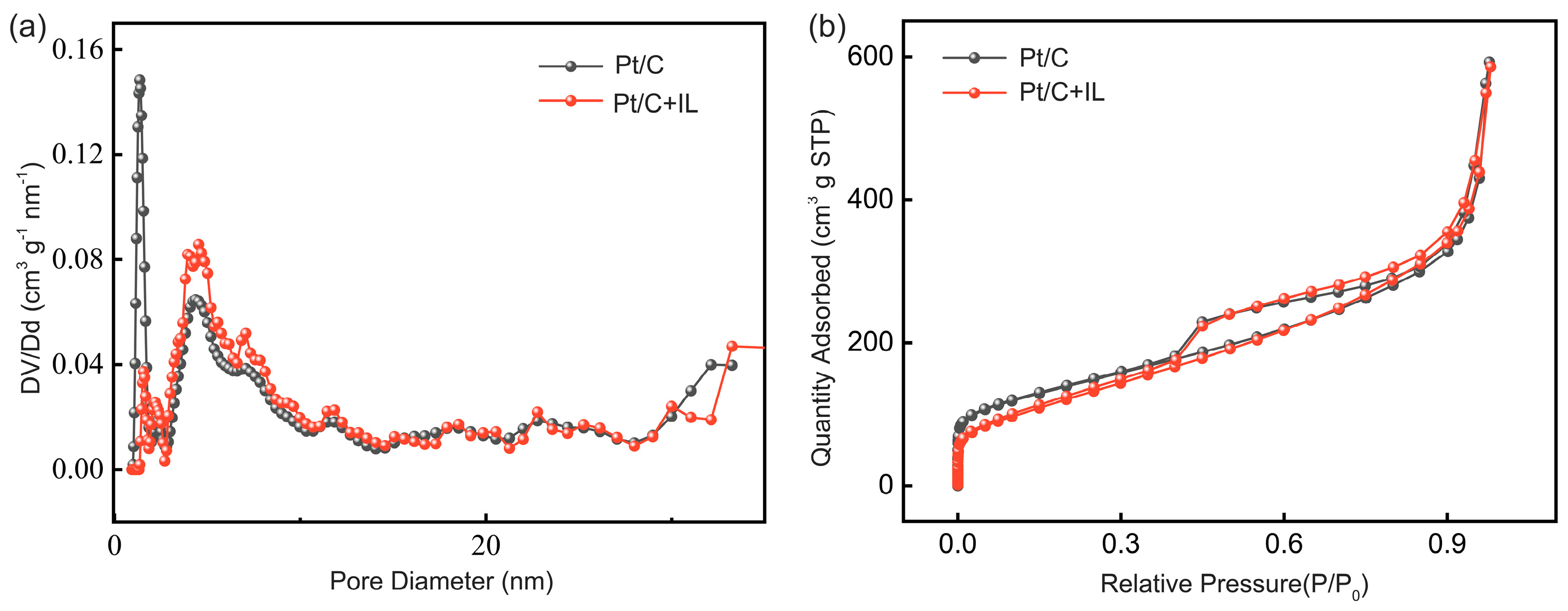
In order to gain a deeper understanding of the modification behavior of IL for the Pt/C catalyst material, nitrogen adsorption analysis was performed to measure the surface area and pore characteristics of the Pt/C electrocatalyst before and after IL modification. The specific surface area of the pristine Pt/C catalyst is 498.9 m2/g, demonstrating the high-surface-area carbon support used. This value decreases to 457.7 m2/g after IL modification. As shown in Figure 2a, the nitrogen adsorption isotherms of both Pt/C and Pt/C+IL can be recognized as a hybrid type of I(b)-II with a type H3 hysteresis, which is similar to other porous carbon materials with a wide pore size distribution [26,27]. Figure 2b shows the derived pore size distribution for the pristine and the modified electrocatalyst. Compared with the pristine electrocatalyst, the number of microporous pores (<2 nm) dramatically reduces for the IL–modified Pt/C electrocatalyst, while the mesopores (2–50 nm) are basically unchanged, indicating that IL preferentially fills the microporous structures of Pt/C. Similarly, Duclaux et al. investigated the adsorption of ILs on carbon materials and found that IL adsorbed preferentially in micropores of the activated carbon rather than in mesopores [28]. Oxygen transport in the catalyst and support is a combination of dissolution and diffusion processes [29]. Since the diffusion process of oxygen in the micropores is limited, the highly oxygen-soluble IL promotes the dissolution of oxygen, while the hydrophobicity of the IL effectively discharges water from the micropores and facilitates the transport of oxygen to the catalyst surface.
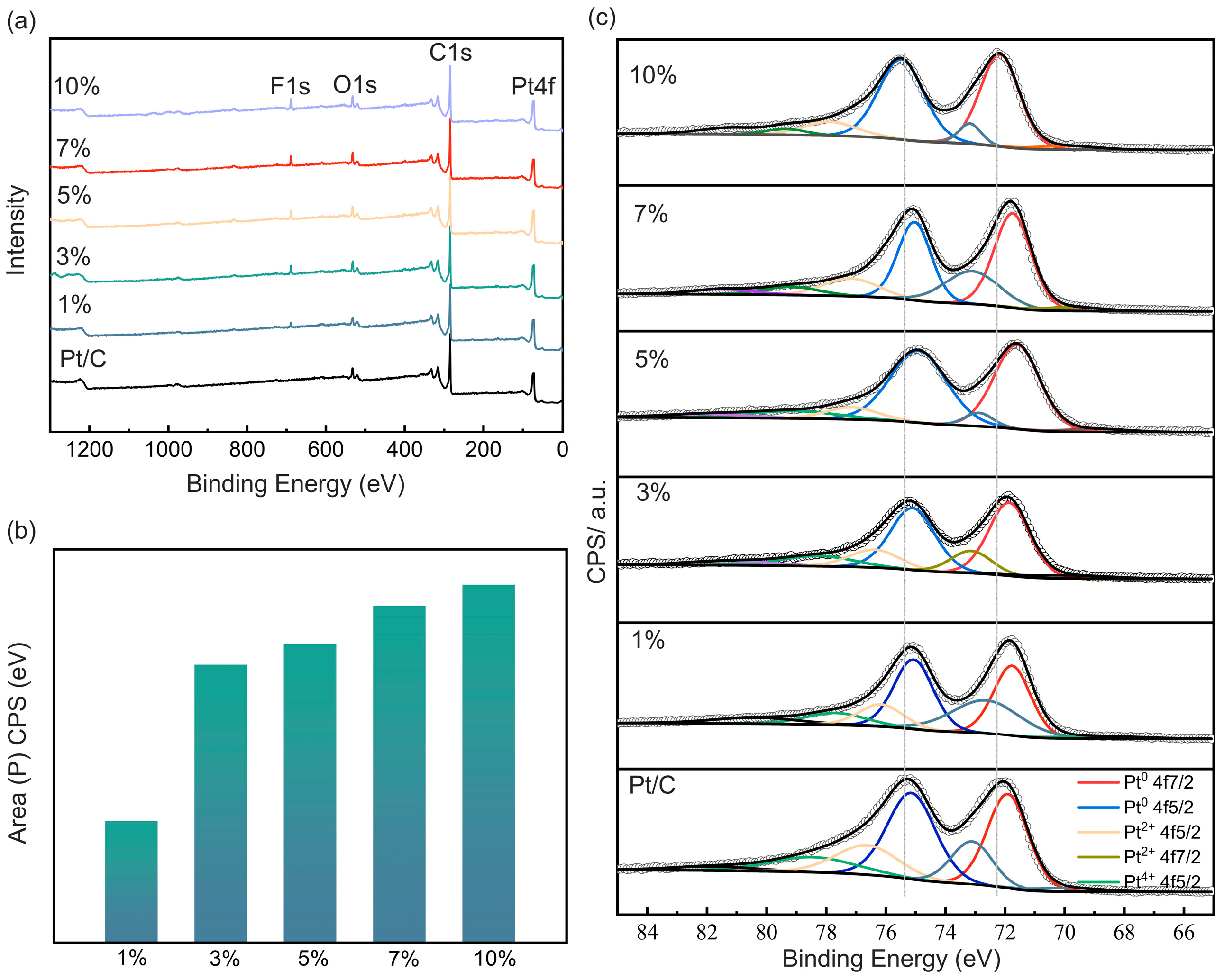
The elemental composition and electronic properties of the catalyst were characterized by X-ray photoelectron spectroscopy (XPS) analysis. The XPS spectrum shown in Figure 3a contains the core energy levels of Pt 4f, C 1s, O 1s, and F 1s in the Pt/C+ILs catalyst, confirming the presence of O, F, and S elements in the catalyst. According to Figure 3b, the peak area of F1s increases with the increasing content of the modified IL, which can be attributed to the successful modification of the catalyst nanoparticle surface using ILs [30]. Figure 3c shows that the catalyst spectrum can be divided into two distinct peaks in the Pt 4f region, attributed to Pt 4f5/2 and Pt 4f7/2 [31]. In the Pt 4f region, the binding energy of IL–modified Pt/C shows a more significant negative shift than that of pristine Pt/C, indicating that the addition of IL changes the electron cloud density around the Pt atoms of the catalyst. This negative shift has been reported to enhance ORR activity [17,24].
The Fourier transform infrared spectroscopy (FTIR) patterns for the pristine and modified electrocatalysts are shown in Figure 4. The interaction of IL with the Pt/C catalyst was demonstrated by comparing the changes in the characteristic peaks of IL before and after adsorption. Comparison of the FTIR spectra of the catalyst before and after IL adsorption shows that the positions of the characteristic peaks of the catalyst have changed. The change in the characteristic peaks of Pt/C+IL catalysts in the range of 1000 cm−1~1600 cm−1 can be attributed to the stretching vibration of the C–F single bond, C–C bond, C=C and S=O double bond in the ILs [32], where the wavelength at 1120 cm−1 corresponds to the C–F single bond of the ionic liquid and 1347 cm−1 corresponds to the S=O double bond. The wavelength at 1223 cm−1 corresponds to the C-C bond in [beti] and 1590 cm−1 corresponds to the C=C bond in [MTBD]+ [33]. The peak with a wavelength of 1223 cm−1 and 1590 cm−1 indicates the successful adsorption of IL onto the Pt/C catalysts. Therefore, these peaks indicate the successful adsorption of IL onto the Pt/C catalysts.

2.2. Electrochemical Measurements

In order to investigate the influence of the IL modification on the electrocatalytic activity of the catalyst, linear scanning voltammetry (LSV) analysis was performed with the half-cell RDE measurement. Figure 5a shows the LSV curves in O2-saturated 0.1 M HClO4 at room temperature for commercial Pt/C and Pt/C+[MTBD][beti] electrocatalysts. The half-wave potential of the catalyst increases with the increase in IL, from 0.8 V for Pt/C to 0.82 V for 1 wt% IL, and then to 0.83 V and 0.88 V for 3 wt% and 5 wt%; finally, the addition of IL reaches the maximum value 0.9 V at 7%. A further increase in the IL amount to 10% leads to a drop of the half-wave potential. The mass activity of the catalysts at 0.9 V vs. RHE was then calculated, and shown in Figure 5b. The mass activity of the IL–modified Pt/C catalysts increased by a factor of 3.2, from 76.57 mA/mgPt for the pristine Pt/C to 240.37 mA/mgPt for the one modified with 7% IL. This significant improvement of the ORR activity can be attributed to the adsorbed [MTBD][beti] inhibiting the formation of Pt oxides and attenuating the Pt–O interactions, thus protecting the active sites of the catalysts from the inactive oxide [17,34]. Overall, IL molecules will preferentially interact with those low-coordinated Pt sites, thus enhancing ORR performance [13]. However, a higher IL loading (i.e., 10 wt%) has a negative impact on ORR performance, regardless. This is due to the fact that the excess IL forms a much thicker layer, and thus, a long diffusion path, which restricts the diffusion of O2 to the catalytic sites, resulting in a lower O2 concentration at the catalytic cites and a lower ORR reaction rate [14].
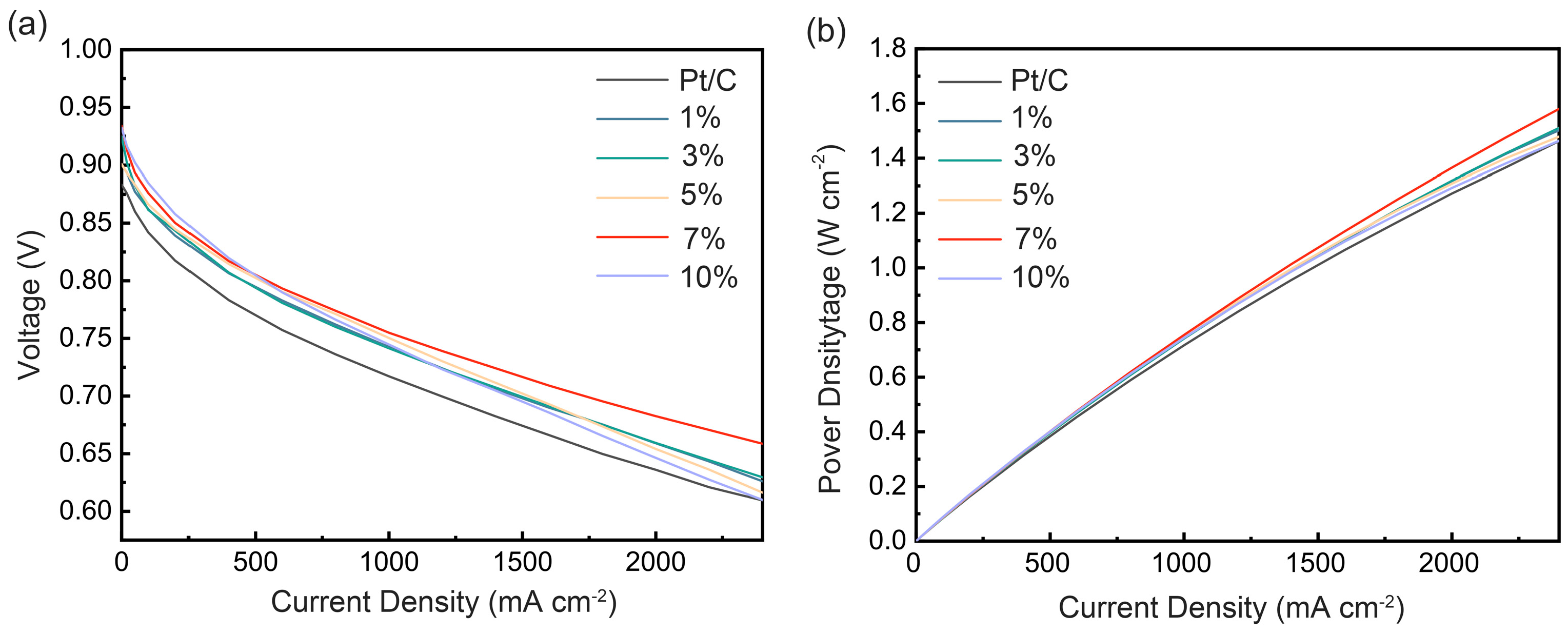
Figure 6a,b show the polarization curves and power density curves for the MEAs with cathodes composed of the pristine Pt/C and IL–modified Pt/C catalysts. MEAs with the IL–modified Pt/C catalysts showed better power performance than the unmodified Pt/C catalyst over the entire current density region studied. The degree of improvement is related to the amount of the added IL. When the IL content is 7%, the improvement in power performance reaches the highest level. At a current density of 2.4 A/cm2, the power density increases from 1.46 W/cm2 for the pristine Pt/C electrocatalyst to 1.60 W/cm2 for the one modified with 7% IL. This improvement can be explained by two reasons. (i) In the low-current-density region, the high solubility of O2 in IL increases the oxygen concentration on the catalyst surface to facilitate the reaction; and, at the same time, IL can reach the active sites of the Pt nanoparticles below the very top surface of the catalyst support, e.g., those trapped in the micropores, thus increasing the available sites for oxygen adsorption, which improves ORR kinetics during the fuel cell operation. (ii) In the high-current-density region, due to the hydrophobicity of IL, the water generated by the reaction can be quickly excluded from the catalyst surface, preventing it from covering on the catalyst surface, which provides more TPB active sites and lowers the resistance of the reactant O2 transport inside the catalyst layer, thus improving the fuel cell performance. However, the power density decreases with IL addition up to 10%. This is due to the excessive IL adsorption covering too much surface of the electrocatalyst nanoparticles, resulting in larger oxygen transport resistance inside the catalyst layer, and excessive IL clogging in the internal microporous structure of the catalyst, which ultimately leads to a decrease in the power density of the fuel cell during operation.
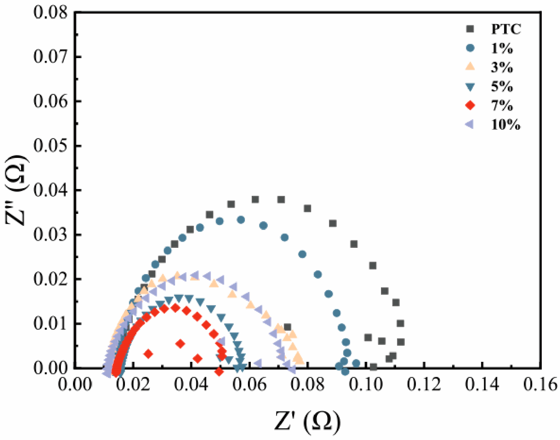
To further understand performance enhancement mechanisms, EIS analysis was performed at 0.9 V for the MEAs, and the results are shown in Figure 7. At a high potential and low current density, the main impedance is contributed by the charge transfer resistance represented by the diameter of the impedance semicircle on the EIS spectra, reflecting the catalytic kinetic performance of the electrode [35]. It can be seen that the impedance semicircle diameter starts to decrease with the increasing IL addition, which indicates an improvement in the charge transfer performance. The 7% IL addition shows the minimum charge transfer resistance, which is consistent with the power performance obtained in Figure 6a,b. The EIS results tested by Arezoo Avid [36] show that proton conductivity is proportional to pore filling, but higher proton conductivity comes at the cost of greater local oxygen transport resistance. Therefore, the best performing IL should be the one that achieves a compromise between the two. This is consistent with the LSV and power density test results.
Compared to the results reported with the low-Pt-loading Pt/C electrocatalyst in the literature [12,13,14,15,16], a higher ionic liquid content is required to reach the optimal power performance here for the high-loading Pt/C, i.e., 7 wt% for 60 wt% Pt/C vs. 2–3 wt% for the 20 wt% Pt/C. Together with the XRD peak change and the XPS shift, these demonstrate the adsorption of IL mainly on the Pt nanoparticle catalyst surface. This could be ascribed to the much higher affinity between the IL and the metal surface [25,37,38] compared to the carbon surface. Furthermore, IL also has a good trend to fill the micropores of the carbon support, and this has also been demonstrated in the IL modification of carbonaceous and ZIF-based electrocatalysts [18,19], where a high optimal IL loading of 20% has been reported. This understanding further demonstrates the importance of using IL to modify electrocatalysts and the tune of the IL loading based on the properties of the catalysts and pore structure of the catalyst support.

3. Materials and Methods

3.1. Materials

Commercial Pt/C catalyst (60 wt%) was purchased from SINO-PLATINUM METALS Co., Ltd. (Kunming, China). Nafion ionomer aqueous dispersion (5 wt%) was purchased from Aladdin Reagents (Shanghai, China) Co; M788.12 (12 μm) Proton Exchange Membrane was purchased from Gore (Shanghai, China); Isopropanol (99.9%) was purchased from Chengdu Chron Chemical Co (Chengdu, China). MTBD (7-methyl-1,5,7-triazabicyclo[4.4.0]dec-5-ene) and Li[beti] (Li bis(perfluoroethylsulfonyl)imide) were purchased from Shanghai Macklin Biochemical Co., Ltd. (Shanghai, China). All the chemicals were used as received without further purification.

3.2. Synthesis of IL [MTBD][beti]

The [MTBD][beti] IL was synthesized according to the method reported in the literature [11]. Typically, an equimolar amount of precursor 7-methyl-1,5,7-triazabicyclo[4.4.0]dec-5-ene [MTBD] and the lithium salt of bis(perfluoroethylsulfonyl)imide [beti] (3 M) are dissolved in ultrapure water and placed in ice water until 0 °C. Then, an equimolar amount of nitric acid is added into [MTBD]. After neutralization, the [beti] solution is mixed with [MTBD], and IL is precipitated as a viscous hydrophobic fluid phase under the aqueous phase. IL is washed several times with deionized water and then placed in a vacuum drying oven at 70 °C for 12 h to remove residual water. After that, IL is dissolved with isopropanol into a 10 mg/mL solution for the following medication application.

3.3. [MTBD][beti] Modification of the Commercial Pt/C Electrocatalyst

To process commercial Pt/C using [MTBD][beti] impregnation, firstly, 30 mg of commercial Pt/C nanoparticle electrocatalysts was dispersed in the designed amount of IPA according to the required concentration of IL. Then, a 10 mg/mL [MTBD][beti] solution was added into IPA to form a 6 mL suspension. To ensure IL was fully dispersed on the catalyst surface, the suspension was sonicated for 30 min, then vacuum-adsorbed at 30 °C for 30 min and left to stand in a vacuum desiccator until the volume was reduced to 0.5 mL. Finally, the suspension was vacuum-dried at 60 °C for 12 h to obtain the modified catalysts.

3.4. Physical Characterization

The chemical status of Pt in the Pt/C electrocatalysts was analyzed using X-ray photoelectron spectroscopy (XPS) analysis (Thermo Scientific K-Alpha spectrometer with Al Κα source). Data analysis was conducted using Avantage software (Avantage 5.948), with the correction of the C 1s peak at 284.8 eV as a reference. Specific surface area and pore distribution were determined by BET analysis (Quantachrome-EVO). X-ray diffraction (XRD) patterns were recorded using an X-ray diffractometer (Rigaku Ultma IV) at 40 kV and 30 mA with Cu Kα (λ = 0.15418 nm) radiation. The scans covered a 2θ range from 20° to 90° with a step size of 0.02° and a scan rate of 2°/min.

3.5. Electrochemical Measurement

The ORR activity of the catalysts was determined using a three-electrode system with a potentiostat CHI700E. The electrolyte used was 0.1 M HClO4. The working electrode was a glassy carbon rotating disc electrode (RDE) with a geometric area of 0.196 cm2. The reference electrode was an Ag/AgCl electrode, and the counter electrode was a platinum mesh attached to a platinum wire. To prepare the working electrode, 2 mg of a dried catalyst was added into a sample vial, to which 2.23 mL of ultrapure water and 0.74 mL of isopropanol were added, and finally 30 μL of perfluorosulfonic acid ionomer dispersion (5 wt%) was added to keep the concentration at 0.4 mg/mL (based on the mass of Pt). Afterwards, the catalyst dispersion was transferred to a sonicator for sonication and dispersion for 30 min to obtain the catalyst suspension for testing. In total, 10 μL of the catalyst suspension was uniformly added dropwise onto the RDE surface with a loading of 20 μg/cm2, after which it was baked dry using an infrared lamp for subsequent use.
The ORR activity of the catalysts was investigated by linear sweep voltammetry (LSV). The LSV curve was recorded by negative-scanning the working electrode in an aqueous solution with oxygen-saturated 0.1 M HClO4 by adjusting the speed of the working electrode to 1600 rpm, at a scan rate of 20 mV/s and a scan range from −0.2 V to 0.9 V. The mass activity (MA) of Pt in the catalyst was calculated using Equations (1) and (2), where i is the experimentally measured current, id is the diffusion-limiting current, and ik is the kinetic current density of the catalyst at 0.9 V (vs. RHE).
1 i = 1 i d + 1 i k
M A = i k P t l o a d i n g

3.6. MEA Fabrication and Fuel Cell Test

The commercial Pt/C electrocatalyst (60 wt%) and Nafion ionomer suspension (5 wt%) were added to IPA to create the catalyst ink. The recipe was used at the following weight ratios: 0.4 ionomer-to-carbon ratio (I/C), solution concentration of 8 mg/mL, and mass ratio of IPA/ultrapure water = 9:1. The suspension was ultrasonicated for 30 min, then was sprayed onto both sides of the proton exchange membrane using a spray gun. The Pt load was controlled at around 0.2 mgPt/cm2 through repeated layer spraying, drying and weighing steps. Then, a piece of GDL with an area of 25 cm2 was sandwiched on both sides of the catalyst-loaded proton exchange membrane, and hot-pressed at 130 °C under a pressure of 0.8 MPa for two minutes to create MEAs. A PTFE gasket with a thickness of 80 μm was used at both sides.
The MEAs were tested at 80 °C using an ITECH IT8816 fuel cell test rig with fully humidified H2/O2 at the anode and cathode sides, with the flow rate and back pressure of 500/1000 sccm and 150/150 kPa, respectively. The MEA was hydrated at 0.6 V for 6 h until a stable current density was obtained. Thus, the polarization curve was recorded between 0.5 A and 65 A using the U.S. Department of Energy (DoE) protocol. For each point, the data were logged for 2 min and the average value for the final 30 s was used. Electrochemical impedance spectroscopy (EIS) measurements were performed at 0.9 V in the frequency range from 100 kHz to 0.1 Hz with an amplitude of 5 mV.

4. Conclusions

In this work, the IL modification for the commonly used commercial Pt/C electrocatalyst (60 wt% Pt/C) was systematically studied to understand the performance enhancement mechanisms. The XRD peak intensity change and the XPS shift revealed that the adsorption of IL mainly happened on the Pt nanoparticle catalyst surface. Furthermore, the pore characterization indicated that IL tends to enter the micropores of the catalyst support and interact with the Pt nanoparticles trapped in these pores, facilitating oxygen and proton transport to the electrocatalyst trapped in those pores, which cannot be reached by the proton conduction ionomer. Due to the high oxygen solubility of IL, the good cover of the IL on the Pt surface and the penetration in the micropores led to improved ORR kinetics. Furthermore, IL hydrophobicity helped protect the catalyst surface from water to keep the active reaction sites during the fuel cell operation. At a high-catalyst loading of 60 wt% Pt on carbon support, more Pt nanoparticles on the surface and trapped in the support pores led to a much higher 7 wt% IL loading on the catalyst surface to achieve the optimal modification effect, compared to 2–3 wt% IL for the 20 wt% Pt/C electrocatalysts reported in the literature. Thus, the active tendency of IL modification monitored by the half-cell measurement in the liquid electrolyte was directly transported to the cathode of the PEMFC single cells. The understanding obtained here regarding IL adsorption behavior could also be extended to design new catalyst structures combined with the IL modification to further improve the fuel cell power performance. For scale up and practical applications, the consideration of the challenges of the high cost of the chemicals used to prepare the ionic liquids and further process optimization are required.

Author Contributions

Conceptualization, F.C., Y.Z., Y.H. and S.D.; Methodology, F.C., F.Y. and Y.Y.; Software, F.C. and Y.G.; Validation, F.C., X.L. and Y.L.; Investigation, F.C. and S.D.; Resources, Y.Z. and Y.H.; Writing—original draft, F.C.; Writing—review & editing, F.C., Y.Z., Y.H. and S.D.; Visualization, F.C., Y.Z. and Y.H.; Supervision, Y.Z. and Y.H.; Funding acquisition, Y.Z. and Y.H. All authors have read and agreed to the published version of the manuscript.

Funding

The study was financially supported by grants from Yunnan Science and Technology Department (202303AK140020 and 202305AO350010).

Data Availability Statement

The raw data supporting the conclusions of this article will be made available by the authors on request.

Conflicts of Interest

The authors declare no conflict of interest.

References

  1. Zhao, Z.; Liu, Z.; Zhang, A.; Yan, X.; Xue, W.; Peng, B.; Xin, H.L.; Pan, X.; Duan, X.; Huang, Y. Graphene-nanopocket-encaged PtCo nanocatalysts for highly durable fuel cell operation under demanding ultralow-Pt-loading conditions. Nat. Nanotechnol. 2022, 17, 968–975. [Google Scholar] [CrossRef] [PubMed]
  2. Jiao, K.; Xuan, J.; Du, Q.; Bao, Z.; Xie, B.; Wang, B.; Zhao, Y.; Fan, L.; Wang, H.; Hou, Z. Designing the next generation of proton-exchange membrane fuel cells. Nature 2021, 595, 361–369. [Google Scholar] [CrossRef]
  3. Tang, M.; Zhang, S.; Chen, S. Pt utilization in proton exchange membrane fuel cells: Structure impacting factors and mechanistic insights. Chem. Soc. Rev. 2022, 51, 1529–1546. [Google Scholar] [CrossRef]
  4. Zhao, J.; Tu, Z.; Chan, S.H. Carbon corrosion mechanism and mitigation strategies in a proton exchange membrane fuel cell (PEMFC): A review. J. Power Sources 2021, 488, 229434. [Google Scholar] [CrossRef]
  5. Li, H.; You, J.; Feng, Y.; Yan, X.; Yin, J.; Luo, L.; He, M.; Cheng, X.; Shen, S.; Zhang, J. Comprehensive understanding of oxygen transport at Gas/ionomer/electrocatalyst triple phase boundary in PEMFCs. Chem. Eng. J. 2023, 478, 147454. [Google Scholar] [CrossRef]
  6. Yarlagadda, V.; Carpenter, M.K.; Moylan, T.E.; Kukreja, R.S.; Koestner, R.; Gu, W.; Thompson, L.; Kongkanand, A. Boosting Fuel Cell Performance with Accessible Carbon Mesopores. ACS Energy Lett. 2018, 3, 618–621. [Google Scholar] [CrossRef]
  7. Guo, Y.; Yang, D.; Li, B.; Yang, D.; Ming, P.; Zhang, C. Effect of Dispersion Solvents and Ionomers on the Rheology of Catalyst Inks and Catalyst Layer Structure for Proton Exchange Membrane Fuel Cells. ACS Appl. Mater. Interfaces 2021, 13, 27119–27128. [Google Scholar] [CrossRef]
  8. Han, B.; Yu, S.; Wang, Z.; Zhu, H. Imidazole polymerized ionic liquid as a precursor for an iron-nitrogen-doped carbon electrocatalyst used in the oxygen reduction reaction. Int. J. Hydrogen Energy 2020, 45, 29645–29654. [Google Scholar] [CrossRef]
  9. Liu, Y.; Cui, J.; Wang, H.; Wang, K.; Tian, Y.; Xue, X.; Qiao, Y.; Ji, X.; Zhang, S. Ionic liquids as a new cornerstone to support hydrogen energy. Green Chem. 2023, 25, 4981–4994. [Google Scholar] [CrossRef]
  10. Zhang, G.-R.; Etzold, B.J. Ionic liquids in electrocatalysis. J. Energy Chem. 2016, 25, 199–207. [Google Scholar] [CrossRef]
  11. Snyder, J.; Fujita, T.; Chen, M.; Erlebacher, J. Oxygen reduction in nanoporous metal–ionic liquid composite electrocatalysts. Nat. Mater. 2010, 9, 904–907. [Google Scholar] [CrossRef] [PubMed]
  12. Snyder, J.; Livi, K.; Erlebacher, J. Oxygen Reduction Reaction Performance of [MTBD][beti]-Encapsulated Nanoporous NiPt Alloy Nanoparticles. Adv. Funct. Mater. 2013, 23, 5494–5501. [Google Scholar] [CrossRef]
  13. Zhang, G.-R.; Wolker, T.; Sandbeck, D.J.S.; Munoz, M.; Mayrhofer, K.J.J.; Cherevko, S.; Etzold, B.J.M. Tuning the Electrocatalytic Performance of Ionic Liquid Modified Pt Catalysts for the Oxygen Reduction Reaction via Cationic Chain Engineering. ACS Catal. 2018, 8, 8244–8254. [Google Scholar] [CrossRef] [PubMed]
  14. Zhang, G.-R.; Munoz, M.; Etzold, B.J. Boosting performance of low temperature fuel cell catalysts by subtle ionic liquid modification. ACS Appl. Mater. Interfaces 2015, 7, 3562–3570. [Google Scholar] [CrossRef] [PubMed]
  15. Zhang, G.-R.; Yong, C.; Shen, L.-L.; Yu, H.; Brunnengräber, K.; Imhof, T.; Mei, D.; Etzold, B.J. Increasing accessible active site density of non-precious metal oxygen reduction reaction catalysts through ionic liquid modification. ACS Appl. Mater. Interfaces 2023, 15, 18781–18789. [Google Scholar] [CrossRef] [PubMed]
  16. Zhang, H.; Liang, J.; Xia, B.; Li, Y.; Du, S. Ionic liquid modified Pt/C electrocatalysts for cathode application in proton exchange membrane fuel cells. Front. Chem. Sci. Eng. 2019, 13, 695–701. [Google Scholar] [CrossRef]
  17. Liu, W.; Di, S.; Wang, F.; Zhu, H. Ionic liquid modified fct-PtCo/C@ILs as high activity and durability electrocatalyst for oxygen reduction reaction. Int. J. Hydrogen Energy 2022, 47, 6312–6322. [Google Scholar] [CrossRef]
  18. Qiao, M.; Tang, C.; Tanase, L.C.; Teodorescu, C.M.; Chen, C.; Zhang, Q.; Titirici, M.-M. Oxygenophilic ionic liquids promote the oxygen reduction reaction in Pt-free carbon electrocatalysts. Mater. Horiz. 2017, 4, 895–899. [Google Scholar] [CrossRef]
  19. Wang, M.; Zhang, H.; Thirunavukkarasu, G.; Salam, I.; Varcoe, J.R.; Mardle, P.; Li, X.; Mu, S.; Du, S. Ionic liquid-modified microporous ZnCoNC-based electrocatalysts for polymer electrolyte fuel cells. ACS Energy Lett. 2019, 4, 2104–2110. [Google Scholar] [CrossRef]
  20. Wang, C.; Kong, Y.; Soldemo, M.; Wu, Z.; Tissot, H.; Karagoz, B.; Marks, K.; Stenlid, J.H.; Shavorskiy, A.; Kokkonen, E. Stabilization of Cu2O through site-selective formation of a Co1Cu hybrid single-atom catalyst. Chem. Mater. 2022, 34, 2313–2320. [Google Scholar] [CrossRef]
  21. Addanki Tirumala, R.T.; Ramakrishnan, S.B.; Mohammadparast, F.; Khatri, N.; Arumugam, S.M.; Tan, S.; Kalkan, A.K.; Andiappan, M. Structure–Property–Performance Relationships of Dielectric Cu2O Nanoparticles for Mie Resonance-Enhanced Dye Sensitization. ACS Appl. Nano Mater. 2022, 5, 6699–6707. [Google Scholar] [CrossRef]
  22. Cozzi, D.; De Bonis, C.; D’Epifanio, A.; Mecheri, B.; Felice, V.; Tavares, A.; Licoccia, S. Functionalized metal oxides for PEMFC applications. ECS Trans. 2011, 41, 2297. [Google Scholar] [CrossRef]
  23. Zhang, P.; Huang, S.-Y.; Popov, B.N. Mesoporous tin oxide as an oxidation-resistant catalyst support for proton exchange membrane fuel cells. J. Electrochem. Soc. 2010, 157, B1163. [Google Scholar] [CrossRef]
  24. George, M.; Zhang, G.-R.; Schmitt, N.; Brunnengräber, K.; Sandbeck, D.J.; Mayrhofer, K.J.; Cherevko, S.; Etzold, B.J. Effect of ionic liquid modification on the ORR performance and degradation mechanism of trimetallic PtNiMo/C catalysts. ACS Catal. 2019, 9, 8682–8692. [Google Scholar] [CrossRef] [PubMed]
  25. Lebedeva, O.; Kultin, D.; Zakharov, A.; Kustov, L. Advances in application of ionic liquids: Fabrication of surface nanoscale oxide structures by anodization of metals and alloys. Surf. Interfaces 2022, 34, 102345. [Google Scholar] [CrossRef]
  26. Thommes, M.; Kaneko, K.; Neimark, A.V.; Olivier, J.P.; Rodriguez-Reinoso, F.; Rouquerol, J.; Sing, K.S. Physisorption of gases, with special reference to the evaluation of surface area and pore size distribution (IUPAC Technical Report). Pure Appl. Chem. 2015, 87, 1051–1069. [Google Scholar] [CrossRef]
  27. Wolker, T.; Brunnengraeber, K.; Martinaiou, I.; Lorenz, N.; Zhang, G.-R.; Kramm, U.I.; Etzold, B.J. The effect of temperature on ionic liquid modified Fe-NC catalysts for alkaline oxygen reduction reaction. J. Energy Chem. 2022, 68, 324–329. [Google Scholar] [CrossRef]
  28. Farooq, A.; Reinert, L.; Levêque, J.-M.; Papaiconomou, N.; Irfan, N.; Duclaux, L. Adsorption of ionic liquids onto activated carbons: Effect of pH and temperature. Microporous Mesoporous Mater. 2012, 158, 55–63. [Google Scholar] [CrossRef]
  29. Oh, H.; Lee, Y.i.; Lee, G.; Min, K.; Yi, J.S. Experimental dissection of oxygen transport resistance in the components of a polymer electrolyte membrane fuel cell. J. Power Sources 2017, 345, 67–77. [Google Scholar] [CrossRef]
  30. Kernchen, U.; Etzold, B.; Korth, W.; Jess, A. Solid catalyst with ionic liquid layer (SCILL)–A new concept to improve selectivity illustrated by hydrogenation of cyclooctadiene. Chem. Eng. Technol. Ind. Chem. Plant Equip. Process Eng. Biotechnol. 2007, 30, 985–994. [Google Scholar] [CrossRef]
  31. Peng, X.; Zhao, S.; Omasta, T.J.; Roller, J.M.; Mustain, W.E. Activity and durability of Pt-Ni nanocage electocatalysts in proton exchange membrane fuel cells. Appl. Catal. B Environ. 2017, 203, 927–935. [Google Scholar] [CrossRef]
  32. Chen, Y.; Rodenbücher, C.; Wippermann, K.; Korte, C. Revealing Interfacial Reactions on Pt Electrodes in Ionic Liquids by In Situ Fourier-Transform Infrared Spectroscopy. Anal. Chem. 2023, 95, 16618–16624. [Google Scholar] [CrossRef] [PubMed]
  33. Huang, K.; Morales-Collazo, O.; Chen, Z.; Song, T.; Wang, L.; Lin, H.; Brennecke, J.F.; Jia, H. The Activity Enhancement Effect of Ionic Liquids on Oxygen Reduction Reaction Catalysts: From Rotating Disk Electrode to Membrane Electrode Assembly. Catalysts 2021, 11, 989. [Google Scholar] [CrossRef]
  34. Sobota, M.; Happel, M.; Amende, M.; Paape, N.; Wasserscheid, P.; Laurin, M.; Libuda, J. Ligand effects in SCILL model systems: Site-specific interactions with Pt and Pd nanoparticles. Adv. Mater. 2011, 22, 2617–2621. [Google Scholar] [CrossRef] [PubMed]
  35. Lu, Y.; Du, S.; Steinberger-Wilckens, R. Temperature-controlled growth of single-crystal Pt nanowire arrays for high performance catalyst electrodes in polymer electrolyte fuel cells. Appl. Catal. B Environ. 2015, 164, 389–395. [Google Scholar] [CrossRef]
  36. Avid, A.; Ochoa, J.L.; Huang, Y.; Liu, Y.; Atanassov, P.; Zenyuk, I.V. Revealing the role of ionic liquids in promoting fuel cell catalysts reactivity and durability. Nat. Commun. 2022, 13, 6349. [Google Scholar] [CrossRef] [PubMed]
  37. Lexow, M.; Maier, F.; Steinrück, H.-P. Ultrathin ionic liquid films on metal surfaces: Adsorption, growth, stability and exchange phenomena. Adv. Phys. X 2020, 5, 1761266. [Google Scholar] [CrossRef]
  38. Cremer, T.; Wibmer, L.; Calderón, S.K.; Deyko, A.; Maier, F.; Steinrück, H.-P. Interfaces of ionic liquids and transition metal surfaces—Adsorption, growth, and thermal reactions of ultrathin [C1C1Im][Tf2N] films on metallic and oxidised Ni(111) surfaces. Phys. Chem. Chem. Phys. 2012, 14, 5153–5163. [Google Scholar] [CrossRef]
Figure 1. XRD patterns of the Pt/C electrocatalysts modified with different IL loadings.
Catalysts 14 00344 g001
Figure 2. (a) N2 adsorption-desorption isotherms at 77.15 K for Pt/C and Pt/C+IL electrocatalysts; and (b) pore size distribution obtained from the BJH analysis.
Catalysts 14 00344 g002
Figure 3. (a) XPS survey; (b) F peak intensity; and (c) Pt 4f comparison of the Pt/C electrocatalyst modified with various amounts of IL.
Catalysts 14 00344 g003
Figure 4. FTIR spectra of Pt/C and Pt/C+IL electrocatalysts.
Catalysts 14 00344 g004
Figure 5. (a) ORR polarization curves determined in O2-saturated 0.1 M HClO4 with a scan rate of 20 mV/s at room temperature and a rotation rate of 1600 rpm/min; and (b) mass activity at 0.9 V vs. RHE for the Pt/C electrocatalyst modified with various IL amounts.
Catalysts 14 00344 g005
Figure 6. Performance of MEAs with cathodes composed of Pt/C and Pt/C+IL electrocatalysts in PEMFC single cells: (a) polarization curves and (b) power density curves. They were tested at 80 °C with fully humidified H2/O2, and the flux and back pressure for the anode and the cathode were 500/1000 sccm and 150/150 kPa, respectively.
Catalysts 14 00344 g006
Figure 7. Electrochemical impedance spectra recorded at 0.9 V for the MEAs fabricated with the cathodes composed of Pt/C and Pt/C+IL electrocatalysts.
Catalysts 14 00344 g007
Disclaimer/Publisher’s Note: The statements, opinions and data contained in all publications are solely those of the individual author(s) and contributor(s) and not of MDPI and/or the editor(s). MDPI and/or the editor(s) disclaim responsibility for any injury to people or property resulting from any ideas, methods, instructions or products referred to in the content.