Article

Improvement of Power Density and COD Removal in a Sediment Microbial Fuel Cell with α-FeOOH Nanoparticles

by
Monica Mejía-López
1,
Orlando Lastres
1,
José Luis Alemán-Ramírez
2,
Antonio Verde
1,
José Campos Alvarez
2,
Soleyda Torres-Arellano
3,
Gabriela N. Trejo-Díaz
1,
Pathiyamattom J. Sebastian
2,* and
Laura Verea
1,*
1
Instituto de Investigación e Innovación en Energías Renovables, Universidad de Ciencias y Artes de Chiapas, Tuxtla Gutiérrez 29000, Mexico
2
Instituto de Energías Renovables-Universidad Nacional Autónoma de México Privada Xochicalco, Temixco 62580, Mexico
3
Instituto de Ingeniería-UNAM, Circuito Escolar, Ciudad Universitaria, Mexico City 04510, Mexico
*
Authors to whom correspondence should be addressed.
Catalysts 2024, 14(9), 561; https://doi.org/10.3390/catal14090561
Submission received: 17 May 2024 / Revised: 3 August 2024 / Accepted: 7 August 2024 / Published: 26 August 2024
(This article belongs to the Special Issue Feature Papers in Section "Biomass Catalysis")

Abstract

:
Sediment microbial fuel cells (SMFC) are bioelectrochemical systems that can use different wastes for energy production. This work studied the implementation of nanoparticles (NPs) of α-FeOOH (goethite, which is well-known as a photoactive catalyst) in the electrodes of an SMFC for its potential use for dye removal. The results obtained demonstrate the feasibility of the NPs activation with the electrical potential generated in the electrodes in the SMFC instead of the activation with light. The NPs of α-FeOOH were synthesized using a hydrothermal process, and the feasibility of a conductive bio-composite (biofilm and NPs) formation was proven by X-ray diffraction (XRD) analysis, scanning electron microscopy (SEM), and electrochemical techniques. The improvement of the power density in the cell was more than twelve times higher with the application of the bio-composite, and it is attributed mostly to the presence of NPs. The results also demonstrate the NPs effect on the increase of the electron transfer, which resulted in 99% of the COD removal. The total electrical energy produced in 30 days in the SMFC was 1.2 kWh based on 1 m2 of the geometric area of the anode. The results confirm that NPs of α-FeOOH can be used to improve organic matter removal. Moreover, the energy produced due to its activation through the potential generated between the electrodes suggests the feasibility of its implementation for dye removal.

1. Introduction

Sediment microbial fuel cells are bioelectrochemical systems capable of generating energy in a sustainable way, where microorganisms oxidize an organic substrate and release electrons owing to their metabolic process [1]. SMFCs are capable of producing electrical energy from degraded organic matter in wastewater and sediment [2,3]. The main limitation of this bioelectrochemical system is the low power density produced and the strategy to increase its performance through the anode material improvement [4]. Currently, considerable emphasis has been placed on conductive materials and electrocatalysts, leading to the development of methods for electrode surface modification. For this purpose, nanomaterials are widely used to enhance the redox potential by strengthening the ability of electron transfer [4]. It has been reported that metallic nanoparticles of Fe, Zn, Ni, Cu, and Co can modify the surface of carbonaceous materials, promoting electrochemical activity [5]. However, the implementation of nanoparticles in MFCs and the methods used for their synthesis are limited. To mention a few: magnetic Fe3O4 NPs [6], Fe NPs [7], AuNPs [8], and FeO NPs [9], and their use in SMFCs is barely reported. Some methods and techniques used for the synthesis of these nanoparticles are the solvothermal method, the acid hydrolysis method, the hydrothermal process, and green synthesis using the aqueous extract of the Amaranthus dubius leaf [10,11]. The use of nanoparticles in anodes of SMFCs is relatively new. Pushkar et al. [12] synthesized cerium oxide NPs (CeO2 NPs) through a hydrothermal method for anode and cathode coating of a conductive matrix. This work revealed maximum power densities of 60 mW/m3 when CeO2 NPs were used on the cathode and 43 mW/m3 when the CeO2 NPs were used on the anode, and both results were higher than that where the NPs were not used (14 mW/m3) [12]. A similar work by Xiao et al. [13] where the anode of an SMFC was modified with commercial Fe2O3 nanoparticles and higher organic matter removal was obtained after 50 days. Recently, Yang et al. [4] modified the anode through a chemical process with a 5% w/w graphene oxide (GO) coating in an SMFC with a mariculture system where 95.8% ammonia removal and a maximum power density of 132 mW/m2 was obtained. Also, materials with Fe-like ferric oxide (FeO) used in MFCs have been related to the enhancement of desirable electrode properties such as conductivity, electron transport, and adhesion of exoelectrogenic bacteria [9]. Another material with Fe- is Goethite (α-FeOOH), which is an easily obtained transition metal oxide with low toxicity, high stability, and environmental friendliness [14,15]. It has good electrochemical activity, even when it is supported on carbon surfaces, as it has good photocatalytic activity, high biocompatibility, and capacitance [16].
This work expands the use of α-FeOOH NPs on a carbon material for bioelectroactive biofilm formation to obtain a bioanode used in an SMFC for power generation. The principal purpose of incorporating α-FeOOH NPs is to decrease the resistance of the material, hence improving the electron transfer and also the power density of the SMFC. α-FeOOH NPs were synthesized through a hydrothermal method and deposited on carbon felt. The bioanode characterization and evaluation proved the positive effect of the NPs in the SMFC.

2. Results and Discussion

2.1. Nanoparticle Characterization

2.1.1. XRD Analysis

The XRD pattern of the α-FeOOH NPs synthesized presented two main phases, Figure 1. The main phase was goethite (FeO(OH)), according to the PDF file: 29-0713, which is a mineral of iron (III) oxyhydroxide. The main peaks observed in the XRD pattern at values of 2θ were, 18.8°, 21.2°, 26.3°, 33.2°, 34.7°, 36.1°, 36,7°, 39.1°, 40.0°, 41.2°, 43.2°, 45.0°, 47.3°, 50.6°, 51.5°, 53.2°, 54.2°, 55.3°, 57.4°, 59.0°, 61.5°, 63.4°, 64.0°, 65.6°, 67.1°, 68.5° and 69.1°. This corresponded to the crystal planes (0 2 0), (1 1 0), (1 3 0), (0 2 1), (0 4 0), (1 1 1), (2 0 0), (1 2 1), (1 4 0), (2 2 0), (1 3 1), (0 4 1), (2 1 1), (1 4 1), (2 2 1), (2 4 0), (0 6 0), (2 3 1), (1 5 1), (0 0 2), (3 2 0), (0 6 1), (1 1 2), (3 3 0), (3 0 1) and (1 7 0). The second phase identified was hematite according to the PDF file: 33-0664, exhibiting 2θ values of 24.1°, 35.6°, 49.5° and 62.4° that corresponded to the crystalline planes (0 1 2), (1 1 0), (0 2 4) and (2 1 4), respectively.

2.1.2. SEM-EDS Analysis

The scanning electron micrograph of Figure 2 shows the α-FeOOH NPs analyzed with SEM, displaying rod-shaped morphology of different sizes (Supporting Information can be downloaded at: https://www.mdpi.com/article/10.3390/catal14090561/s1). This can be attributed to the high surface energy of the nanoparticles resulting from the heat treatment of the samples [17]. This nanomaterial was studied due to its capability for dye removal, which is a potential application for microbial fuel cells. This type of morphology has been previously reported as a highly active surface area material compared to other morphologies in the NPs [18,19,20,21]. Liu et al. [22] related the rod length to the time of the hydrothermal process. The average diameter and length of the NPs used were 45.4 ± 1.4 nm and 482 ± 46 nm, respectively.
The analysis of the α-FeOOH NPs with EDS proved the purity of the NPs, and EDS results in Figure 1 show that there is no evidence of traces of other minerals. The composition is summarized in Table 1, where the oxygen and Fe atomic % content were 58.7% and 41.3%, respectively. The type of nanoparticle and its chemical composition could affect the surface heterogeneity of the electrodes, including hydrophobicity and surface charge. The semiconductive NPs behaved similarly to the electroactive bacteria since the NPs (just like each bacteria) are able to oxidize reduced ionic species and transfer electrons to a solid conductive material (Figure 3). The semiconductive NPs can also have a similar behavior as the reduced ionic species produced from the substrate. They can function as electron conductors between microorganisms; therefore, the bacteria adhesion and the biofilm development were positively affected [23,24].

2.2. Biofilm Characterization

2.2.1. EIS Analysis

The effect of α-FeOOH nanoparticles on the charge transfer capacity of the anode was analyzed with the EIS technique. The analysis was performed after the biofilm formation on the electrode of carbon felt, and it was compared to the electrode of carbon felt with NPs and biofilm. Figure 4 shows the equivalent circuit used for the analysis. This is based on the physicochemical model of SMFC composed of carbon felt in contact with electrolyte solution (synthetic wastewater) (see Figure 3). Where R1 is the ohmic resistance, which may be due to anolyte solutions, R2 is the anodic charge transfer resistance. W is the Warburg impedance, and C1 is the capacitance corresponding to the anode/anolyte electrochemical interfaces.
As expected, there was an improvement in the charge transfer capacity of the bioanode with α-FeOOH NPs, as demonstrated in the Nyquist plot of Figure 5. This figure shows that the charge transfer resistance was almost three times lower than that of the anode without the biofilm of bacteria and more than two times lower than that of the bioanode. Table 1 summarizes the EIS results for the three anode configurations. This effect of the presence of NPs has been previously reported [9] to facilitate bioelectrochemical reactions in anodes [25]. The decrease in electron transfer resistance of the anode with α-FeOOH NPs has also been reported with NPs of FeO [25], CeO2 [26], Fe-ZnO [27], and Fe [7]. The ohmic resistance was the same for the anode and the bioanode, but the bioanode with α-FeOOH NPs was almost 17% lower, which improved the charge transfer through the electrolyte. The decrease in the ohmic resistance to 13.0 Ω when the bioanode with α-FeOOH NPs was used agreed with that reported by Xian et al. [16], who reported a resistance of 12.1 Ω. The decrease in the ohmic resistance of FeOOH NPs is due to this material facilitating bioelectrochemical kinetics. This has been observed in other works with FeO NPs [25] and RuO2 [9].
Moreover, iron oxide NPs have magnetic properties, small size, and relatively large surface area, which could have different uses. These include applications for metal ion detection [28], catalysts, and other uses for which hydrophilic properties [29] may be useful. Goethite is a semiconductor, and its nanoparticles also have catalytic properties and a large surface area [30]. Its inclusion in the electrode surface as NPs can increase the contact sites between the electrodes and bacteria and also from one organism to another, which is essential for the viability of the reactions [31]. This last one can be described as a catalytic property that increases electron transfer and decreases the activation potential, potential losses, and resistance to charge transfer reactions.

2.2.2. Cyclic Voltammetry

The anode with carbon felt was analyzed using cyclic voltammetry (CV) before and after adding α-FeOOH NPs and also after the biofilm formation. Figure 6 CV results for the carbon felt anode with α-FeOOH NPs (blue line) shows an oxidation peak at 0.4 V (vs. Ag/AgCl) with a current of 0.3 mA/cm2 and a reduction peak at 0.3 V (vs. Ag/AgCl) with a current of −0.1 mA/cm2. Oxidation peaks of α-FeOOH materials have been observed before at similar potentials [32,33]. The CV results suggest the appearance of redox properties in the carbon felt, which promote the electrochemical activity of the anodic material. The CV results after the biofilm formation on the electrode with NPs of α-FeOOH (red line) showed an oxidation peak at −0.1 V (vs. Ag/AgCl) and 0.3 mA/cm2 and a reduction peak at −0.3 V (vs. Ag/AgCl) and −0.3 mA/cm2. This oxidation peak was similar to that reported for exoelectrogenic microorganisms (−0.1 V) such as Geobacter [34]. The CV results of the anode material with α-FeOOH NPs and with biofilm showed a quasi-reversible electrocatalytic process, which indicates a fast electron transfer [25]. The voltammogram of the bioanode (α-FeOOH NPs with biofilm) also showed a pseudo-capacitive behavior, improving the ability of electron transfer inside the biofilm [35,36,37].

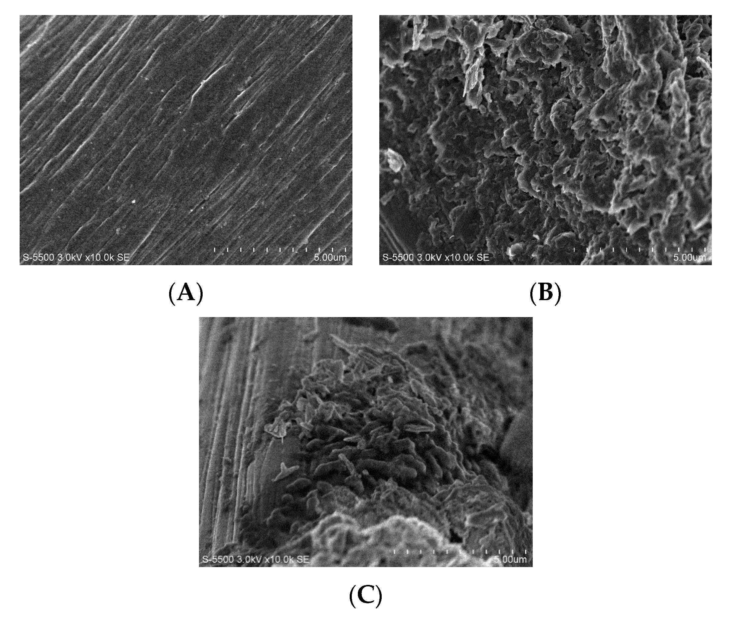
2.2.3. Surface Biofilm Analysis

The surface of the carbon felt anode without biofilm (Figure 7A), with α-FeOOH NPs (Figure 7B), and with α-FeOOH NPs and the biofilm (Figure 7C) were characterized using the SEM technique (Figure 7B). SEM micrographs confirmed the presence of microorganisms adhered to the surface of the material with NPs of α-FeOOH. The exact nature of the microorganisms cannot be conclusively determined from the SEM images. However, the observed morphology closely matched that of Bacillus subtilis, which has been reported as capable of exchanging electrons with electrodes [38].

2.3. Sediment Microbial Fuel Cell Performance

2.3.1. Polarization Curve and Maximum Power Density

The polarization and power density curves were analyzed when the SMFC was operated in two configurations: with the bioanode without NPs and with the bioanode with α-FeOOH NPs (Figure 8a). The results show that the maximum power density of the SMFC with the bioanode and α-FeOOH NPs (4.9 W/m2) was 12 times higher than that of the SMFC with bioanode without NPs (0.388 W/m2). These results of power density are also higher than that of 145.5 mW/m2, as reported by Harshiny et al. [9] In that report, they used carbon paper as anode material and FeO NPs in the MFC. Similarly, our results were also higher than that of 122.6 mW/m2 reported by Xian et al. [16], using carbon paper as anode material and α-FeOOH NPs, H-type dual-chamber MFC (14 mL each Chamber) and pure inoculum (S. loihica PV-4).
The high power density found in this work could be due to the configuration of the cell. For example, it is known that single-chamber cells tend to show higher current densities because the internal resistance is reduced [39]. However, these enhanced results occurred even though the type of inoculum and sediment directly impacts cell performance due to bacteria adaptation to the environment [40,41]. The polarization plot for the microbial fuel cell is presented in Figure 8b. In this figure, the linear voltage drop region is clearly distinguished. This linear relationship between potential and current is a defining characteristic of microbial fuel cells due to their relatively high internal resistance [42]. The presence of the α-FeOOH NPs in the bioanode clearly reduced the ohmic losses of the linear voltage drop region [42] of Figure 8a. These losses can be attributed to the conductivity of the solution, the space between the electrodes, or the contacts between the electrode and the circuit in the SMFC [43]. The internal resistance of the SMFC was calculated according to Logan et al. [42] for the SMFC with the bioanode and α-FeOOH NPs. We found a value of 582 Ω, which is almost six times smaller than that of the bioanode without NPs of 3050 Ω. According to Table 2, where the characteristics of the electrodes were analyzed, we found that the ohmic resistance R1 (resistance of the electrolyte and sediment) [44] for the bioanode with α-FeOOH NPs was slightly lower than that for the bioanode without α-FeOOH NPs. These values were lower than the internal resistances of the SMFC.
The high power density in the cell with α-FeOOH NPs can be attributed to various factors, such as the high surface area of the material due to the presence of nanoparticles and the improved adhesion of exoelectrogenic microorganisms. This helped to decrease the resistance of the composite carbon felt, NPs, and biofilm material and to increase the electron transfer rate, which was also verified by EIS and CV electrochemical analysis.

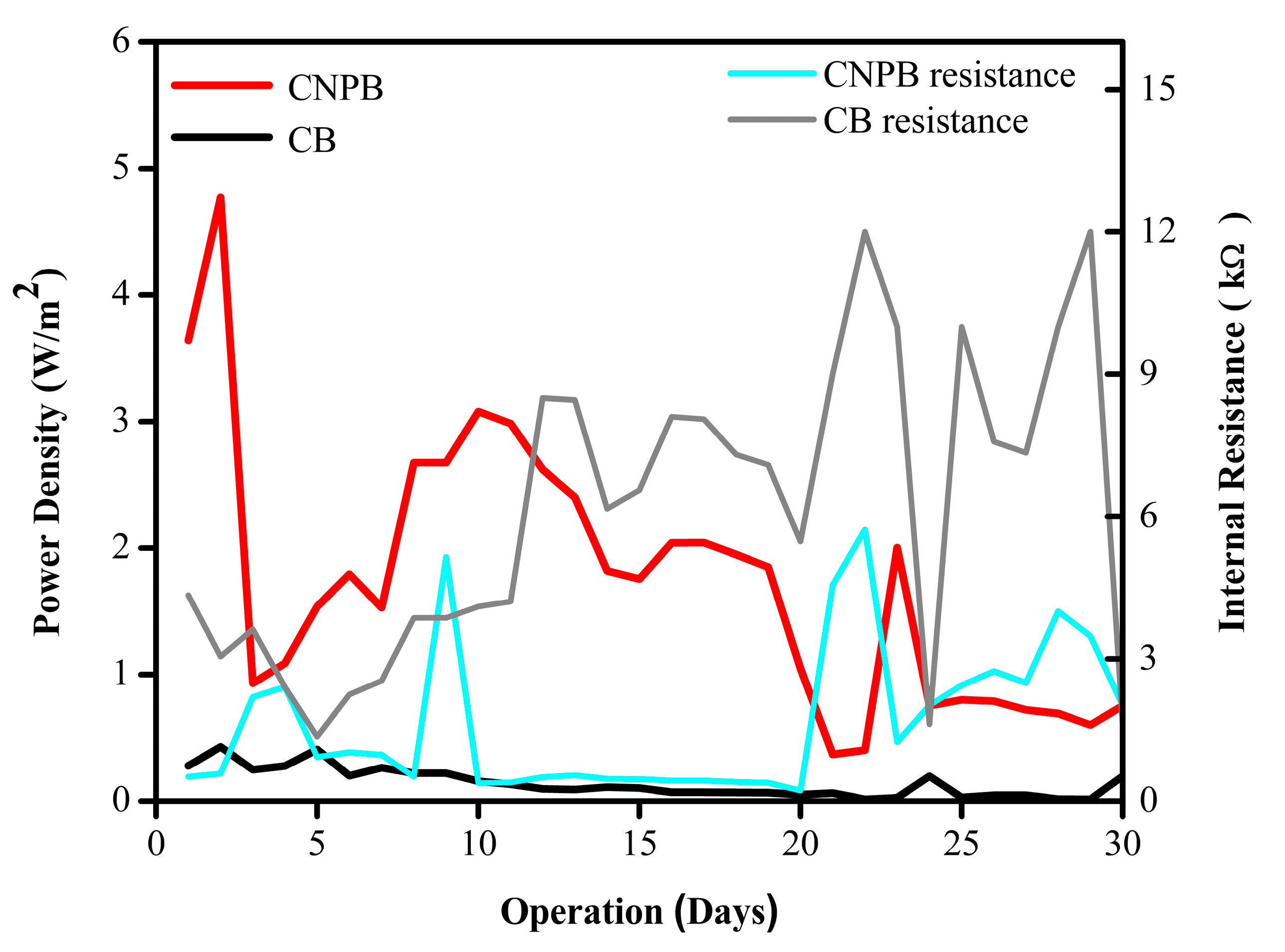
2.3.2. Long-Term Testing of α-FeOOH NPs in the SMFC

The SMFC bioanode with α-FeOOH NPs (SMFC-CNPB) was connected to a 1 kΩ resistor and operated for 30 days for electricity production. The results were compared with those of the SMFC with the bioanode without NPs (SMFC-CB) operated at the same conditions. This resistance was used due to its similarity to the internal resistance of the cell with the highest power density.
The power densities of the two SMFC configurations are shown in Figure 9. The evaluation shows that the SMFC-CNPB registered two peaks of maximum power densities. The first peak occurred on day 2, with a power density of 4.7 W/m2 and an internal resistance of 582 Ω, which was 11 times higher than the SMFC-CB on the same day. The second peak of maximum power density for the SMFC-CNPB was on day 10, with a power density of 3.1 W/m2 and an internal resistance of 380 Ω (Figure 9), which was 19 times higher than that for the SMFC-CB configuration. The power densities registered in this work were higher than those reported for MFCs using different nanoparticles on anodes (Table 2). The increase in the power densities in SMFC-CNPB compared to SMF-CB is due to the increase in the population of the electroactive microorganisms on the surface of the anode material. This is the case since it has been seen that metallic nanoparticles such as Fe and Co promote microorganism growth and accelerate the adhesion of microcells to the anode surface [5,45]. This effect has also been observed in the presence of Fe3O4 nanoparticles which promoted the enrichment of microorganisms on the anode surface. This is due to properties such as rough surface, mesoporous structure, etc. Moreover, Fe as a conducting material created a new transmission path for electrons, which can generate a faster stabilization of the microbial community, as well as an increase in electron transport and current density [46].
During the evaluation process, a downward trend of the power density and an increase in internal resistance were observed (Figure 9). However, the SMFC-CNPB showed higher power density values than the SMFC-CB. The variability in power density and internal resistance over time has been seen in MFCs, and it has been explained by a clogging of the pores due to degradation and accumulation of solids on the electrode [47]. For example, accumulation of calcium and sodium carbonates in the cathode [48] and the progressive loss of nanoparticles in the anode material [49] can result in a decrease in the electron transfer to the collector and ohmic losses. Both of these last two effects would, therefore, lead to an increase in the internal resistance and a decrease in the power density [43,50]. The total electrical energy produced in the SMFCs connected to a 1 kΩ resistor for 30 days, as shown in Figure 8, was 1.2 kWh for SMFC-CNPB and only 0.1 kWh for SMFC-CB, which represents an improvement of more than 10 times. Then, variability in the power density and resistance over time, shown in Figure 9, may be the result of the complex and interdependent biological and chemical processes that take place in a batch reactor, including variations in substrate availability, CO2 produced, and desorbed, and in general, mass transport in a living biofilm.
Table 2. Comparative power densities of MFCs using Fe nanoparticles.
Electrode MaterialCell TypeNanoparticleMaximum Power Density (W/m2)TCOD (%)Ref.
Macroporous sugarcane carbonMFCFe3_[7]
Carbon clothMFCFe3O4494[51]
Carbon fiber feltSMFCFe2O39.8 × 10−3_[13]
Carbon derived from waxMFCβ-FeOOH1.4_[52]
Carbon paperMFCα-FeOOH0.1_[16]
Carbon feltSMFCα-FeOOH4.999This study

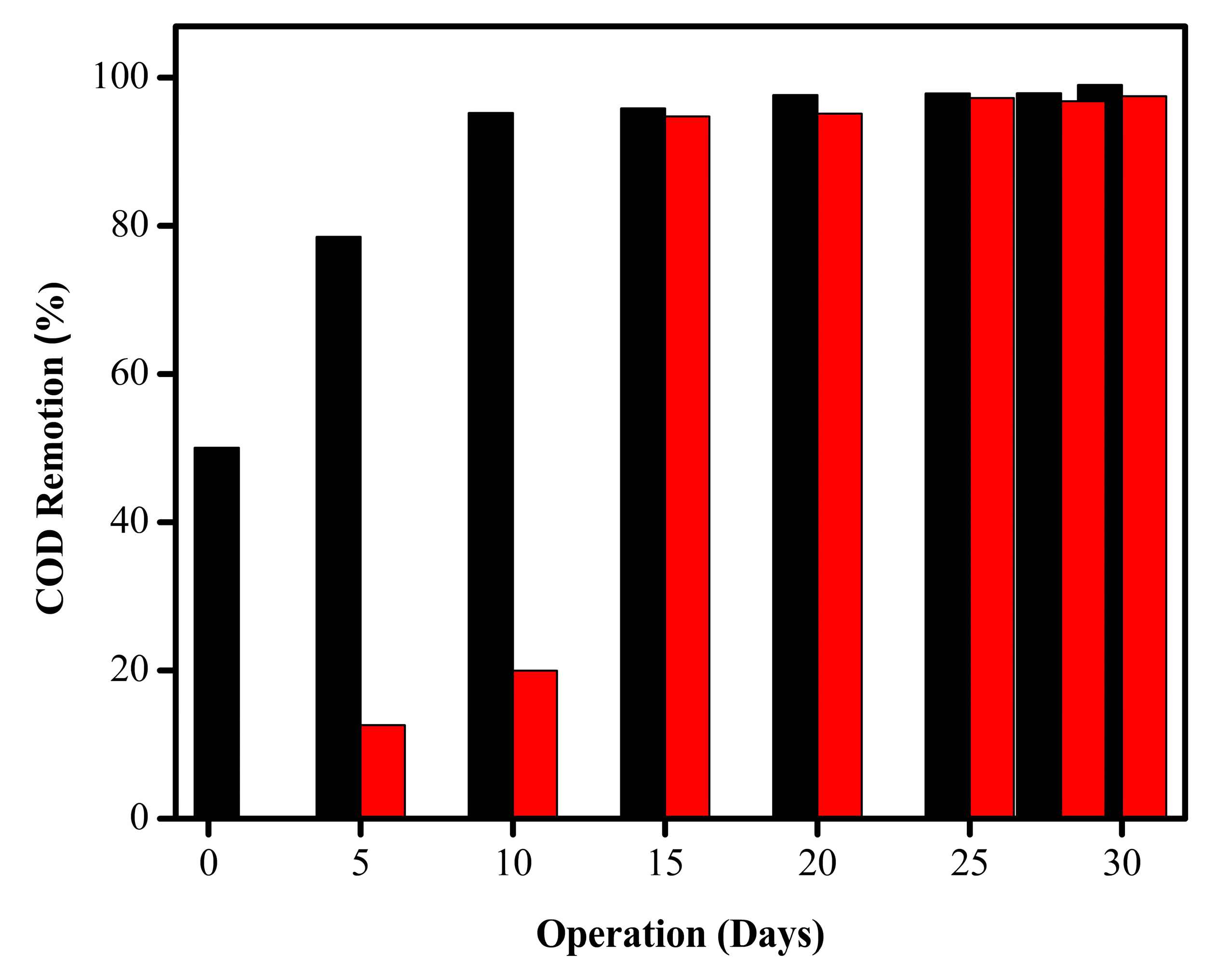
2.4. Total COD Removal

The total COD removed (TCOD) was monitored during the operation of the SMFC with the carbon felt anode in the presence and absence of α-FeOOH NPs by measuring every 5 days over 30 days. The cells were operated in batch mode with an input COD of 800 mg/L, each operating with a different anode. In Figure 10, it can be seen that during the first 10 days, the COD removal increased from 50% to 95% for the carbon felt + NPs + biofilm composite material; subsequently, the TCOD increased very little until reaching a maximum TCOD of 99%. For the carbon felt+ biofilm anode configuration, the TCOD increased from 0 to 20% in the first 10 days. Then, on day 15, it increased to 95%, after which it achieved a maximum of 97%. According to the results obtained, it can be concluded that the nanoparticles in the anode helped the rapid adaptation and formation of the biofilm on the electrode, which influenced the increase in the removal of organic material. This effect has also been observed in copper-doped iron oxide nanoparticles (Cu-doped FeO) and Fe/Fe2O3 nanoparticle electrodes used in MFCs for the removal of organic matter. In those reported examples, the nanoparticles improved COD removal from 64 to 75% in the first case [53] and from 50 to 88.5% in the second one [54].

3. Materials and Methods

3.1. Hydrothermal Synthesis of α-FeOOH Nanoparticles

α-FeOOH NPs were synthesized with the methodology described by Xian et al. [16]. It was prepared from a solution consisting of 7.3 g of Fe(NO3)3·9H2O (Sigma Aldrich, Saint Louis, MO, USA) dissolved in 20 mL of distilled water under continuous stirring. To this mixture, 4.1 g of KOH (Fermont, Monterrey, Mexico) in 20 mL of distilled water was slowly added. For the hydrothermal method, the final solution was placed in an autoclave at the temperature of 100 °C for 6 h. The α-FeOOH NPs obtained were filtered and washed with distilled water and finally with absolute ethanol. The α-FeOOH NPs were dried at 60 °C for 24 h.

3.2. Fabrication of the Bioanode

Carbon felt material provided by Grupo Rooe (Aculco, Mexico) with a geometric area of 1 × 1 cm2 was used as the conductive material for the electroactive biofilm support. The carbon felt was prewashed with 0.05 M sulfuric acid to remove impurities and promote hydrophilic properties, after which it was rinsed with water.
Later, the felt was impregnated by spraying 1 mL of a solution of polyvinyl alcohol (PVA from Sigma Aldrich, Missouri, USA) and α-FeOOH NPs in the ratio of 1:5 (PVA to NPs wt/wt%) according to the methodology reported by M. Harshiny et al. [9]. Afterward, the material was dried in a muffle Yamato Scientific America model FO110CR (Santa Clara, CA, USA) at 60 °C. For the biofilm formation, the material was enriched in a sealed electrochemical cell of 100 mL with 70 mL of seawater and 10 g of fresh marine sediment (the sediment used was coarse with a sandy consistency) with bacteria. This was followed by applying −0.45 V vs. Ag/AgCl 3 M KCl (Sigma Aldrich, Missouri, USA) reference electrode (model OrigaSens OGR006, Rillieux-la-Pape, France) for 5 h at 37 °C, as reported by M. Mejía-López et al. [55].

3.3. α-FeOOH NPs and Bioanode Characterization

The structural characterization of the α-FeOOH NPs was done by X-ray diffraction (XRD) using a Rigaku (Tokyo, Japan) diffractometer model DMAX 2200 with Cu-Kα radiation, λ = 1.5406 Å, in the 2θ range of 10–70°.
The materials were also analyzed with the scanning electron microscope (SEM) Hitachi (Tokyo, Japan) SU 1510 with energy dispersive X-ray spectroscopy (EDS) at 20 kV.
The anode with α-FeOOH NPs was characterized before and after the biofilm formation with cyclic voltammetry (CV), electrochemical impedance spectroscopy (EIS), and scanning electron microscopy (SEM) techniques. The electrochemical characterization was performed with the Solartron Potentiostat (model SI 1287A Hampshire, UK) in a cell with three electrodes, with the bioanode as the working electrode, Ag/AgCl (3 M KCl) as the reference electrode, and a graphite rod (Grupo Rooe, Aculco, Mexico) as a counter electrode. The CV was recorded from −0.7 V to 0.7 V at the scan rate of 1 mV/s. The electrolyte was 100 mM sodium acetate (Fermont, Monterrrey, Mexico) with a carbonate buffer (Fermont, Monterrrey, Mexico) of pH 9. The EIS analysis was carried out with alternating current and voltage amplitude of 50 mV in the frequency range of 100 kHz to 10 mHz. The ohmic resistance, the charge transfer resistance, and the Warburg impedance were determined through Nyquist plots.

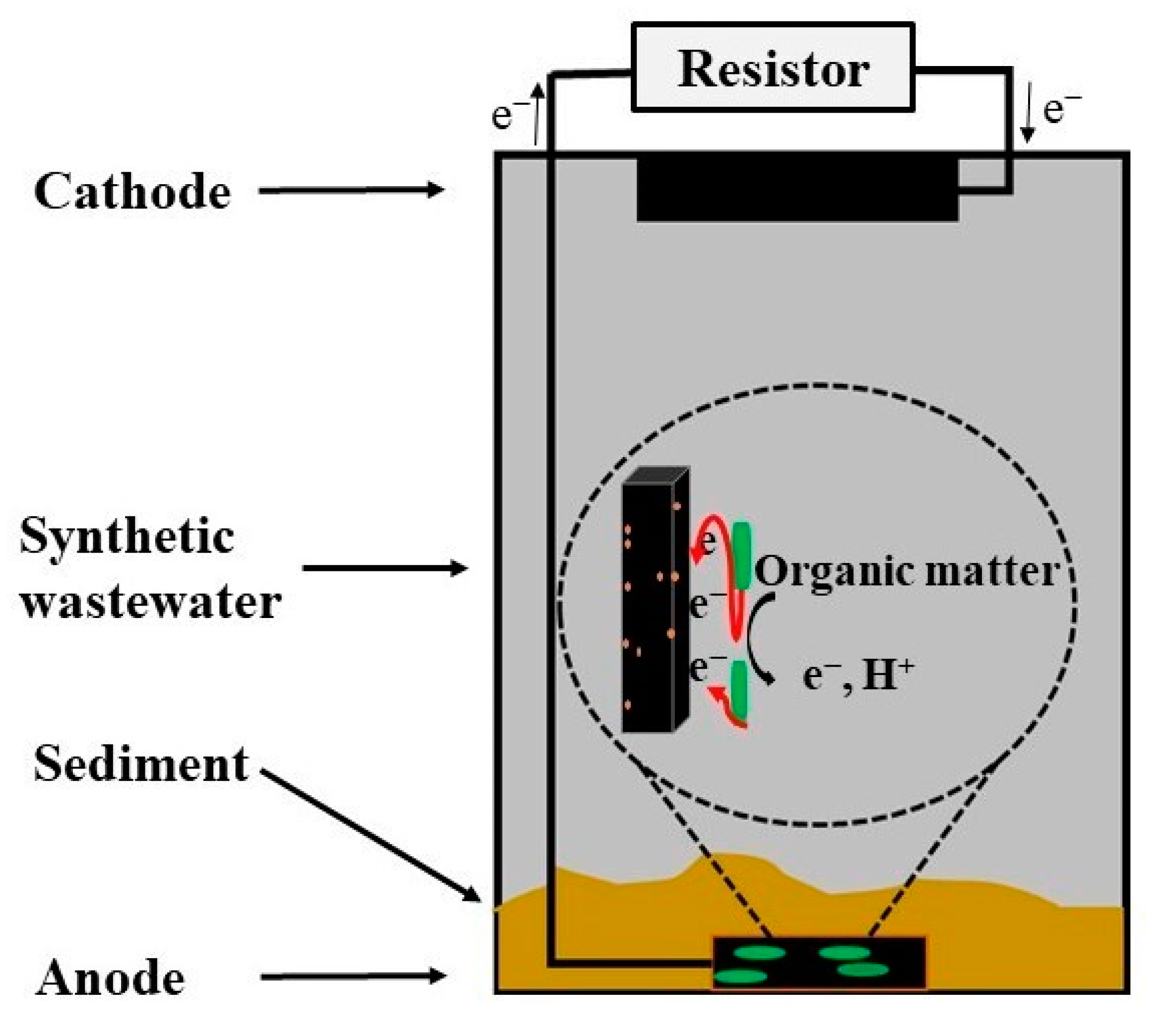
3.4. Sediment Microbial Fuel Cell Operation

The bioanode with NPs was used in a 100 mL SMFC of transparent acrylic cells. The sediment was a sea sediment obtained from Guasave, Sinaloa, Mexico (25°17′27.1″ N 108°30′51.2″ W). The sediment was collected with a nucleator at 10 cm depth and 10 m from the coastline. The bioanode with NPs was located at the bottom of the cell and totally covered with 10 g of wet sediment. The cathode was made of carbon cloth E-TEK (Austin, TX, USA) of 3 × 3 cm2 catalyzed with 0.5 mg Pt/cm2 (20 wt% Pt, E-TEK, TX, USA), and it was located in the electrolyte surface to be in contact with air (Figure 3). The following were used as a medium: 70 mL of synthetic wastewater composed of 1 g/L NH4Cl (Fermont, Monterrrey, Mexico), 1 g/L NaHCO3 (Fermont, Monterrrey, Mexico), 1 g/L Na2CO3 (Fermont, Monterrrey, Mexico), 0.2 g/L K2HPO4 (Fermont, Monterrrey, Mexico), 10 μL vitamin and 10 μL mineral solutions (Sigma Aldrich, Missouri, USA), the carbon source was 20 mM NaCH3COO (Fermont, Monterrrey, Mexico).
The power density of the SMFC was obtained from the polarization curve evaluated by connecting different electrical resistances (Rext) from 0 to 100 KΩ (see Figure 3), and the voltage was recorded with the data acquisition system (2700, Keithley, Cleveland, OH, USA). The internal resistance was obtained with the maximum power density from the power density plot. The energy produced was calculated with the total current registered in the data acquisition system when the SMFC remained connected to a 1 kΩ resistance for 30 days.

3.5. Chemical Oxygen Demand (COD)

The removal of organic matter was determined by the standard method of potassium dichromate (APHA 1998) and parameter analyzer (Hach model DR 900, Loveland, OH, USA) and quantified as chemical oxygen demand calculated with the following Equation (1).
COD   removal   efficiency   % = COD 0 - COD t COD 0 × 100
where: COD0 is initial concentration; CODt is the final concentration [18].

4. Conclusions

In this work, nanoparticles (NPs) of α-FeOOH with high purity were synthesized with a hydrothermal process and were successfully deposited on the carbon electrodes. The selective technique of bacteria colonization used in these electrodes and the electroactive biofilm formation were confirmed to be effective with SEM and CV techniques, respectively. The inclusion of semiconducting NPs in the bioanode resulted in the improvement of the anode performance since the NPs were able to function as the electroactive bacteria and as the solid electrical conducting material in the electrode. This dual capacity was confirmed with the reduction of the internal resistance of the SMFC and the higher electrical current densities. In this work, this capacity allowed the improvement of the power density by more than 10 times that obtained with an SMFC with no NPs in the electrodes. The capacity of the SMFC for organic matter degradation was also improved by up to 90% in COD removal and remained constant after reaching that value. This COD removal occurred while the cell was simultaneously producing electrical energy 10 times more than that of the SMFC without α-FeOOH NPs.

Supplementary Materials

The following supporting information can be downloaded at: https://www.mdpi.com/article/10.3390/catal14090561/s1, Figure S1: EDS spectra of α-FeOOH NPs; Table S1: Minerals in the synthesized α-FeOOH NPs.

Author Contributions

M.M.-L.: Methodology, investigation, and manuscript writing; O.L.: Reviewing and editing; J.L.A.-R.: Methodology and investigation. A.V.: Investigation and methodology. J.C.A.: Investigation; S.T.-A.: Investigation; G.N.T.-D.: Methodology; P.J.S.: Fund acquisition, reviewing and editing; L.V.: Formal analysis and manuscript writing. All authors have read and agreed to the published version of the manuscript.

Funding

This research received no external funding.

Data Availability Statement

Data will be made available on request.

Acknowledgments

Monica Mejía-López is grateful for the postdoctoral scholarship support (420239) from the National Council of Science and Technology (CONAHCYT), México. The authors are grateful to M.C. José Campos Álvarez and Maria Luisa Ramon of IER-UNAM for SEM/EDS and XRD measurements, respectively.

Conflicts of Interest

The authors declare no conflict of interest.

References

  1. Feregrino-Rivas, M.; Ramirez-Pereda, B.; Estrada-Godoy, F.; Cuesta-Zedeño, L.F.; Rochín-Medina, J.J.; Bustos-Terrones, Y.A.; Gonzalez-Huitron, V.A. Performance of a Sediment Microbial Fuel Cell for Bioenergy Production: Comparison of Fluvial and Marine Sediments|. Biomass Bioenergy 2023, 168, 106657. [Google Scholar] [CrossRef]
  2. Abazarian, E.; Gheshlaghi, R.; Mahdavi, M.A. Interactions between Sediment Microbial Fuel Cells and Voltage Loss in Series Connection in Open Channels. Fuel 2023, 332, 126028. [Google Scholar] [CrossRef]
  3. Chi-Wen, L.; Alfanti, L.K.; Cheng, Y.-S.; Liu, S.-H. Enhancing Bioelectricity Production and Copper Remediation in Constructed Single-Medium Plant Sediment Microbial Fuel Cells. Desalination 2022, 542, 116079. [Google Scholar] [CrossRef]
  4. Yang, J.; Zhao, Y.-G.; Liu, X.; Fu, Y. Anode Modification of Sediment Microbial Fuel Cells (SMFC) towards Bioremediating Mariculture Wastewater. Mar. Pollut. Bull. 2022, 182, 114013. [Google Scholar] [CrossRef] [PubMed]
  5. Mohamed, H.O.; Sayed, E.T.; Obaid, M.; Choi, Y.-J.; Park, S.-G.; Al-Qaradawi, S.; Chae, K.-J. Transition Metal Nanoparticles Doped Carbon Paper as a Cost-Effective Anode in a Microbial Fuel Cell Powered by Pure and Mixed Biocatalyst Cultures. Int. J. Hydrogen Energy 2018, 43, 21560–21571. [Google Scholar] [CrossRef]
  6. Miran, F.; Mumtaz, M.W.; Mukhtar, H.; Akram, S. Iron Oxide–Modified Carbon Electrode and Sulfate-Reducing Bacteria for Simultaneous Enhanced Electricity Generation and Tannery Wastewater Treatment. Front. Bioeng. Biotechnol. 2021, 9, 747434. [Google Scholar] [CrossRef]
  7. Song, B.; Li, J.; Wang, Z.; Ali, J.; Wang, L.; Zhang, Z.; Liu, F.; Glebov, E.M.; Zhang, J.; Zhuang, X. N-Doped Fe Nanoparticles Anchored on 3D Carbonized Sugarcane Anode for High Power Density and Efficient Chromium(VI) Removal. J. Environ. Chem. Eng. 2022, 10, 108751. [Google Scholar] [CrossRef]
  8. Magotra, V.K.; Kang, T.W.; Aqueel Ahmed, A.T.; Inamdar, A.I.; Im, H.; Ghodake, G.; Choubey, R.K.; Kumar, V.; Kumar, S. Effect of Gold Nanoparticles Laced Anode on the Bio-Electro-Catalytic Activity and Power Generation Ability of Compost Based Microbial Fuel Cell as a Coin Cell Sized Device. Biomass Bioenergy 2021, 152, 106200. [Google Scholar] [CrossRef]
  9. Harshiny, M.; Samsudeen, N.; Kameswara, R.J.; Matheswaran, M. Biosynthesized FeO Nanoparticles Coated Carbon Anode for Improving the Performance of Microbial Fuel Cell. Int. J. Hydrogen Energy 2017, 42, 26488–26495. [Google Scholar] [CrossRef]
  10. Jamkhande, P.G.; Ghule, N.W.; Bamer, A.H.; Kalaskar, M.G. Metal Nanoparticles Synthesis: An Overview on Methods of Preparation, Advantages and Disadvantages, and Applications. J. Drug Deliv. Sci. Technol. 2019, 53, 101174. [Google Scholar] [CrossRef]
  11. Muthukumar, H.; Matheswaran, M. Amaranthus Spinosus Leaf Extract Mediated FeO Nanoparticles: Physicochemical Traits, Photocatalytic and Antioxidant Activity. ACS Sustain. Chem. Eng. 2015, 3, 3149–3156. [Google Scholar] [CrossRef]
  12. Pushkar, P.; Prakash, O.; Imran, M.; Mungray, A.A.; Kailasa, S.K.; Mungray, A.K. Effect of Cerium Oxide Nanoparticles Coating on the Electrodes of Benthic Microbial Fuel Cell. Sep. Sci. Technol. 2019, 54, 213–223. [Google Scholar] [CrossRef]
  13. Yang, C.; Xiao, N.; Chang, Z.; Huang, J.J.; Zeng, W. Biodegradation of TOC by Nano-Fe2O3 Modified SMFC and Its Potential Environmental Effects. ChemistrySelect 2021, 6, 5597–5602. [Google Scholar] [CrossRef]
  14. Lin, F.; Yuan, M.; Chen, Y.; Huang, Y.; Lian, J.; Qiu, J.; Xu, H.; Li, H.; Yuan, S.; Zhao, Y.; et al. Advanced Asymmetric Supercapacitor Based on Molybdenum Trioxide Decorated Nickel Cobalt Oxide Nanosheets and Three-Dimensional α-FeOOH/RGO. Electrochim. Acta 2019, 320, 134580. [Google Scholar] [CrossRef]
  15. Tian, C.; Yuan, P.; Huang, W.; Song, F.; Zhao, W. MoS2 Nanosheets Embedded in α-FeOOH as an Efficient Cathode for Enhanced MFC-Electro-Fenton Performance in Wastewater Treatment. Environ. Res. 2023, 216, 114818. [Google Scholar] [CrossRef] [PubMed]
  16. Xian, J.; Ma, H.; Li, Z.; Ding, C.; Liu, Y.; Yang, J.; Cui, F. α-FeOOH Nanowires Loaded on Carbon Paper Anodes Improve the Performance of Microbial Fuel Cells. Chemosphere 2021, 273, 129669. [Google Scholar] [CrossRef] [PubMed]
  17. Godwin, J.; Abdus-Salam, N.; Haleemat, A.I.; Bello, M.O.; Inyang, E.D.; Alkali, M.I.; Tripathy, B.C. High Performance Nanohybrid ZnO-α-FeOOH Nanocomposite Prepared for Toxic Metal Ions Removal from Wastewater: Combined Sorption and Desorption Studies. Inorg. Chem. Commun. 2022, 145, 109900. [Google Scholar] [CrossRef]
  18. Godwin, J.; Abdus-Salam, N.; Haleemat, A.I.; Panda, P.K.; Panda, J.; Tripathy, B.C. Facile Synthesis of Rod-like α-FeOOH Nanoparticles Adsorbent and Its Mechanism of Sorption of Pb(II) and Indigo Carmine in Batch Operation. Inorg. Chem. Commun. 2022, 140, 109346. [Google Scholar] [CrossRef]
  19. Malathi, A.; Arunachalam, P.; Madhavan, J.; Al-Mayouf, A.M.; Ghanem, M.A. Rod-on-Flake α-FeOOH/BiOI Nanocomposite: Facile Synthesis, Characterization and Enhanced Photocatalytic Performance. Colloids Surf. A Physicochem. Eng. Asp. 2018, 537, 435–445. [Google Scholar] [CrossRef]
  20. Mineo, G.; Bruno, L.; Bruno, E.; Mirabella, S. WO3 Nanorods Decorated with Very Small Amount of Pt for Effective Hydrogen Evolution Reaction. Nanomaterials 2023, 13, 1071. [Google Scholar] [CrossRef]
  21. Barai, H.R.; Banerjee, A.N.; Hamnabard, N.; Joo, S.W. Synthesis of Amorphous Manganese Oxide Nanoparticles-to-Crystalline Nanorods through a Simple Wet-Chemical Technique Using K+ Ions as a ‘Growth Director’ and Their Morphology-Controlled High Performance Supercapacitor Applications. RSC Adv. 2016, 6, 78887–78908. [Google Scholar] [CrossRef]
  22. Liu, H.; Zou, J.; Ding, Y.; Liu, B.; Wang, Y. Novel α-FeOOH Corner-Truncated Tetragonal Prisms: Crystal Structure, Growth Mechanism and Lithium Storage Properties. J. Appl. Electrochem. 2019, 49, 657–669. [Google Scholar] [CrossRef]
  23. Fan, Y.; Xu, S.; Schaller, R.; Jiao, J.; Chaplen, F.; Liu, H. Nanoparticle Decorated Anodes for Enhanced Current Generation in Microbial Electrochemical Cells. Biosens. Bioelectron. 2011, 26, 1908–1912. [Google Scholar] [CrossRef] [PubMed]
  24. Kato, S.; Nakamura, R.; Kai, F.; Watanabe, K.; Hashimoto, K. Respiratory Interactions of Soil Bacteria with (Semi)Conductive Iron-Oxide Minerals. Environ. Microbiol. 2010, 12, 3114–3123. [Google Scholar] [CrossRef] [PubMed]
  25. Lv, Z.; Xie, D.; Yue, X.; Feng, C.; Wei, C. Ruthenium Oxide-Coated Carbon Felt Electrode: A Highly Active Anode for Microbial Fuel Cell Applications. J. Power Sources 2012, 210, 26–31. [Google Scholar] [CrossRef]
  26. Yin, Y.; Huang, G.; Zhou, N.; Liu, Y.; Zhang, L. Increasing Power Generation of Microbial Fuel Cells with a Nano-CeO2 Modified Anode. Energy Sources Part A Recovery Util. Environ. Eff. 2016, 38, 1212–1218. [Google Scholar] [CrossRef]
  27. Muthukumar, H.; Mohammed, S.N.; Chandrasekaran, N.; Sekar, A.D.; Pugazhendhi, A.; Matheswaran, M. Effect of Iron Doped Zinc Oxide Nanoparticles Coating in the Anode on Current Generation in Microbial Electrochemical Cells. Int. J. Hydrogen Energy 2019, 44, 2407–2416. [Google Scholar] [CrossRef]
  28. Lakshmipriya, T.; Gopinath, S.C.B. Introduction to Nanoparticles and Analytical Devices. In Nanoparticles in Analytical and Medical Devices; Elsevier: Amsterdam, The Netherlands, 2021; pp. 1–29. [Google Scholar]
  29. Sahu, R.; Parkhey, P. Advancements in Bioelectrochemical System-Based Wastewater Treatment: A Review on Nanocatalytic Approach. Sustain. Energy Technol. Assess. 2021, 48, 101558. [Google Scholar] [CrossRef]
  30. Guo, H.; Barnard, A.S. Thermodynamic Modelling of Nanomorphologies of Hematite and Goethite. J. Mater. Chem. 2011, 21, 11566. [Google Scholar] [CrossRef]
  31. Savla, N.; Anand, R.; Pandit, S.; Prasad, R. Utilization of Nanomaterials as Anode Modifiers for Improving Microbial Fuel Cells Performance. J. Renew. Mater. 2020, 8, 1581–1605. [Google Scholar] [CrossRef]
  32. Yao, Y.; Hou, C.; Zhang, X. Construct α-FeOOH-Reduced Graphene Oxide Aerogel as a Carrier for Glucose Oxidase Electrode. Membranes 2022, 12, 447. [Google Scholar] [CrossRef] [PubMed]
  33. Meng, K.; Hu, X.; Zhang, Y.; Zeng, T.; Wan, Q.; Lai, G.; Chen, X.; Yang, N. A Versatile Sensing Platform Based on FeOOH Nanorod/Expanded Graphite for Electrochemical Quantification of Bioanalytes. J. Electroanal. Chem. 2021, 902, 115803. [Google Scholar] [CrossRef]
  34. Dai, K.; Yan, Y.; Wang, Q.-T.; Zheng, S.-J.; Huang, Z.-Q.; Sun, T.; Zeng, R.J.; Zhang, F. Electricity Production and Key Exoelectrogens in a Mixed-Culture Psychrophilic Microbial Fuel Cell at 4 °C. Appl. Microbiol. Biotechnol. 2022, 106, 4801–4811. [Google Scholar] [CrossRef] [PubMed]
  35. Tang, J.; Yuan, Y.; Liu, T.; Zhou, S. High-Capacity Carbon-Coated Titanium Dioxide Core–Shell Nanoparticles Modified Three Dimensional Anodes for Improved Energy Output in Microbial Fuel Cells. J. Power Sources 2015, 274, 170–176. [Google Scholar] [CrossRef]
  36. Zallouz, S.; Pronkin, S.N.; Le Meins, J.-M.; Pham-Huu, C.; Matei Ghimbeu, C. New Development in Carbon-Based Electrodes and Electrolytes for Enhancement of Supercapacitor Performance and Safety. In Renewable Energy Production and Distribution; Elsevier: Amsterdam, The Netherlands, 2023; Volume 2, pp. 353–408. [Google Scholar]
  37. Kurzweil, P. CAPACITORS|Electrochemical Metal Oxides Capacitors. In Encyclopedia of Electrochemical Power Sources; Elsevier: Amsterdam, The Netherlands, 2009; pp. 665–678. [Google Scholar]
  38. Kandpal, R.; Nara, S.; Shahadat, M.; Ansari, M.O.; Alshahrie, A.; Ali, S.W.; Ahammad, S.Z.; Malhotra, B.D. Impedance Spectroscopic Study of Biofilm Formation on Pencil Lead Graphite Anode in Microbial Fuel Cell. J. Taiwan Inst. Chem. Eng. 2021, 128, 114–123. [Google Scholar] [CrossRef]
  39. Roy, H.; Rahman, T.U.; Tasnim, N.; Arju, J.; Rafid, M.M.; Islam, M.R.; Pervez, M.N.; Cai, Y.; Naddeo, V.; Islam, M.S. Microbial Fuel Cell Construction Features and Application for Sustainable Wastewater Treatment. Membranes 2023, 13, 490. [Google Scholar] [CrossRef] [PubMed]
  40. Jiang, D.; Li, B.; Jia, W.; Lei, Y. Effect of Inoculum Types on Bacterial Adhesion and Power Production in Microbial Fuel Cells. Appl. Biochem. Biotechnol. 2010, 160, 182–196. [Google Scholar] [CrossRef] [PubMed]
  41. Salar-Garcia, M.J.; Obata, O.; Kurt, H.; Chandran, K.; Greenman, J.; Ieropoulos, I.A. Impact of Inoculum Type on the Microbial Community and Power Performance of Urine-Fed Microbial Fuel Cells. Microorganisms 2020, 8, 1921. [Google Scholar] [CrossRef] [PubMed]
  42. Logan, B.E.B. Microbial Fuel Cells; Wiley: Hoboken, NJ, USA, 2008; ISBN 9780470239483. [Google Scholar]
  43. Simeon, M.I.; Asoiro, F.U.; Aliyu, M.; Raji, O.A.; Freitag, R. Polarization and Power Density Trends of a Soil-based Microbial Fuel Cell Treated with Human Urine. Int. J. Energy Res. 2020, 44, 5968–5976. [Google Scholar] [CrossRef]
  44. Liang, P.; Huang, X.; Fan, M.-Z.; Cao, X.-X.; Wang, C. Composition and Distribution of Internal Resistance in Three Types of Microbial Fuel Cells. Appl. Microbiol. Biotechnol. 2007, 77, 551–558. [Google Scholar] [CrossRef]
  45. Zhao, Y.N.; Li, X.F.; Ren, Y.P.; Wang, X.H. Effect of Fe(III) on the Performance of Sediment Microbial Fuel Cells in Treating Waste-Activated Sludge. RSC Adv. 2016, 6, 47974–47980. [Google Scholar] [CrossRef]
  46. Pan, X.; Wang, W.; Chen, Y.; Wen, Q.; Li, X.; Lin, C.; Wang, J.; Xu, H.; Yang, L. Bio-Electrocatalyst Fe3O4/Fe@C Derived from MOF as a High-Performance Bioanode in Single-Chamber Microbial Fuel Cell. Biochem. Eng. J. 2022, 187, 108611. [Google Scholar] [CrossRef]
  47. Vilajeliu-Pons, A.; Puig, S.; Salcedo-Dávila, I.; Balaguer, M.D.; Colprim, J. Long-Term Assessment of Six-Stacked Scaled-up MFCs Treating Swine Manure with Different Electrode Materials. Environ. Sci. Water Res. Technol. 2017, 3, 947–959. [Google Scholar] [CrossRef]
  48. Jiang, D.; Curtis, M.; Troop, E.; Scheible, K.; McGrath, J.; Hu, B.; Suib, S.; Raymond, D.; Li, B. A Pilot-Scale Study on Utilizing Multi-Anode/Cathode Microbial Fuel Cells (MAC MFCs) to Enhance the Power Production in Wastewater Treatment. Int. J. Hydrogen Energy 2011, 36, 876–884. [Google Scholar] [CrossRef]
  49. Hidalgo, D.; Tommasi, T.; Velayutham, K.; Ruggeri, B. Long Term Testing of Microbial Fuel Cells: Comparison of Different Anode Materials. Bioresour. Technol. 2016, 219, 37–44. [Google Scholar] [CrossRef] [PubMed]
  50. Oguz Koroglu, E.; Civelek Yoruklu, H.; Demir, A.; Ozkaya, B. Scale-Up and Commercialization Issues of the MFCs. In Microbial Electrochemical Technology; Elsevier: Amsterdam, The Netherlands, 2019; pp. 565–583. [Google Scholar]
  51. Chen, H.; Zhao, C.; Song, Y.; Wang, X.; Zhu, L.; Ai, T. Performance Improvement of Microbial Fuel Cells by Fermentation Gas Driven Fluidization of Magnetite Nanoparticles and Carbon Particles. J. Power Sources 2023, 555, 232365. [Google Scholar] [CrossRef]
  52. Tang, X.; Liu, L.; Cui, Y. β-FeOOH Modified Carbon Monolith Anode Derived from Wax Gourd for Microbial Fuel Cells. Int. J. Hydrogen Energy 2022, 47, 4838–4845. [Google Scholar] [CrossRef]
  53. Sekar, A.D.; Jayabalan, T.; Muthukumar, H.; Chandrasekaran, N.I.; Mohamed, S.N.; Matheswaran, M. Enhancing Power Generation and Treatment of Dairy Waste Water in Microbial Fuel Cell Using Cu-Doped Iron Oxide Nanoparticles Decorated Anode. Energy 2019, 172, 173–180. [Google Scholar] [CrossRef]
  54. Mohamed, H.O.; Obaid, M.; Poo, K.-M.; Ali Abdelkareem, M.; Talas, S.A.; Fadali, O.A.; Kim, H.Y.; Chae, K.-J. Fe/Fe2O3 Nanoparticles as Anode Catalyst for Exclusive Power Generation and Degradation of Organic Compounds Using Microbial Fuel Cell. Chem. Eng. J. 2018, 349, 800–807. [Google Scholar] [CrossRef]
  55. Mejía-López, M.; Verea, L.; Sebastian, P.J.; Verde, A.; Perez-Sarinana, B.Y.; Campos, J.; Hernández-Romano, J.; Moeller-Chávez, G.E.; Lastres, O.; Monjardín-Gámez, J.d.J. Improvement of Biofilm Formation for Application in a Single Chamber Microbial Electrolysis Cell. Fuel Cells 2021, 21, 317–327. [Google Scholar] [CrossRef]
Figure 1. X-ray diffractogram of the α-FeOOH NPs.
Catalysts 14 00561 g001
Figure 2. SEM image showing the morphology of α-FeOOH NPs.
Catalysts 14 00561 g002
Figure 3. Schematic representation of bioelectrochemical processes in the sediment microbial fuel cell.
Catalysts 14 00561 g003
Figure 4. The equivalent circuit of the bioelectrode with α-FeOOH nanoparticles.
Catalysts 14 00561 g004
Figure 5. EIS analysis of the anodes used in SMFC. Anode without bacteria (blue line), bioanode (with bacteria) of carbon felt (black line), and bioanode (with bacteria) with α-FeOOH NPs (red line).
Catalysts 14 00561 g005
Figure 6. Cyclic voltammetry results (scan rate of 1 mV/s) of the carbon felt anode without bacteria (black line), carbon felt anode with α-FeOOH NPs without bacteria (blue line), and carbon felt with α-FeOOH NPs with bacteria biofilm formation process (red line).
Catalysts 14 00561 g006
Figure 7. SEM images: (A) electrode without biofilm, (B) electrode with NPs of α-FeOOH, (C) bioelectrode with NPs of α-FeOOH and biofilm.
Catalysts 14 00561 g007
Figure 8. (a) Maximum power density and (b) polarization curve of the Sediment Microbial Fuel Cell using a bioanode of carbon felt (black line) and bioanode of carbon felt with α-FeOOH NPs (red line).
Catalysts 14 00561 g008
Figure 9. Power density and internal resistance of the SMFC with anodes made of carbon felt containing α-FeOOH NPs and bacteria (CNPB) vs. carbon felt with bacteria (CB).
Catalysts 14 00561 g009
Figure 10. TCOD in the SMFC with carbon felt bioanode containing α-FeOOH NPs (black) vs. SMFC with carbon felt bioanode without NPs (red), connected to 1 kΩ resistor.
Catalysts 14 00561 g010
Table 1. Results of the EIS analysis.
EXPR1 (Ω)C1 (F)R2 (Ω)W (Ω)
Anode186.9 × 10−34.60.3
Bioanode183.8 × 10−34.20.3
Bioanode with FeOOH NPs132.1 × 10−31.50.2
Disclaimer/Publisher’s Note: The statements, opinions and data contained in all publications are solely those of the individual author(s) and contributor(s) and not of MDPI and/or the editor(s). MDPI and/or the editor(s) disclaim responsibility for any injury to people or property resulting from any ideas, methods, instructions or products referred to in the content.

