Article

Engineered CoS/Ni3S2 Heterointerface Catalysts Grown Directly on Carbon Paper as an Efficient Electrocatalyst for Urea Oxidation

1
Chemistry Department, College of Science and Humanities, Prince Sattam Ben Abdul-Aziz University, Al-Kharj 11942, Saudi Arabia
2
Chemistry Department, College of Applied Science, Taiz University, Taiz 6803, Yemen
3
Electrochemical Sciences Research Chair, Department of Chemistry, Science College, King Saud University, P.O. Box 2455, Riyadh 11451, Saudi Arabia
4
Department of Physiology, Saveetha Dental College & Hospitals, Saveetha Institute of Medical and Technical Sciences (SIMATS), Saveetha University, Chennai 600077, India
5
Department of Microbiology, DKM College for Women (Autonomous), Vellore 632001, India
6
Department of Chemistry, Vellore Institute of Technology, Vellore 632014, India
7
Department of Chemistry, Muthurangam Government Arts College (Autonomous), Vellore 632002, India
8
Physics Department, Faculty of Education, Taiz University, Taiz 12372, Yemen
*
Authors to whom correspondence should be addressed.
Catalysts 2024, 14(9), 570; https://doi.org/10.3390/catal14090570
Submission received: 28 June 2024 / Revised: 20 August 2024 / Accepted: 23 August 2024 / Published: 28 August 2024
(This article belongs to the Section Electrocatalysis)

Abstract

:
Developing highly efficient and stable electrocatalysts for urea electro-oxidation reactions (UORs) will improve wastewater treatment and energy conversion. A low-cost cobalt sulfide-anchored nickel sulfide electrode (CoS/Ni3S2@CP) was synthesized by electrodeposition in DMSO solutions and found to be highly effective and long-lasting. The morphology and composition of catalyst surfaces were examined using comprehensive physicochemical and electrochemical characterization. Specifically, CoS/Ni3S2@CP electrodes require a potential of 1.52 volts for a 50 mA/cm2 current, confirming CoS in the heterointerface CoS/Ni3S2@CP catalyst. Further, the optimized CoS/Ni3S2@CP catalyst shows a decrease of 100 mV in the onset potential (1.32 VRHE) for UORs compared to bare Ni3S2@CP catalysts (1.42 VRHE), demonstrating much greater performance of UORs. As compared to Ni3S2@CP, CoS/Ni3S2@CP exhibits twofold greater UOR efficiency as a result of a larger electroactive surface area. The results obtained indicate that the synthetic CoS/Ni3S2@CP catalyst may be a favorable electrode material for managing urea-rich wastewater and generating H2.

1. Introduction

The development of clean energy technology is a crucial step in the progress towards establishing a sustainable human society. Effective technologies that utilize clean energy not only enhance energy efficiency but also offer simultaneous answers to environmental problems [1,2]. Due to its large energy density and eco-friendliness, hydrogen fuel is increasingly being considered as a promising alternative to renewable energy resources (e.g., wind, solar, and hydropower) [3,4,5,6]. Among hydrogen production approaches, electrochemical water-splitting [7], which involves the oxygen evolution reaction (OER) and hydrogen evolution reactions (HERs), stands out for its notable efficiency and eco-friendliness [8,9]. The OER still remains a bottleneck in water electrolysis due to its sluggish kinetics and a substantial overpotential requirement [10,11,12]. Thus, recent research has sought to address this issue by exploring alternatives to the OER that involve easier oxidation processes for anodes. It not only reduces hydrogen fuel production potential, but is also more energy efficient [13,14,15,16]. Among the innovative approaches is electrocatalysis of ready-to-oxidize small organic compounds, such as methanol [17], ethanol [14], and urea [15,18,19,20].
Compared to water splitting (1.23 V), urea electrolysis generates hydrogen more efficiently, with a lower theoretical voltage (0.37 V) [21,22,23,24]. Due to its optimal energy density of 16.9 MJL−1, urea is gaining recognition as a viable and sustainable energy source [21]. In addition to its favorable attributes, it is also non-toxic, non-flammable, readily available, incombustible, non-volatile, stable, and renewable. However, the byproducts of urea decomposition, including nitrate (NO3) and ammonia (NH3), pollute the environment and pose health risks [25]. Alternatively, in a basic environment, the UOR yields harmless nitrogen (N2) and carbonate (CO32−), which are soluble in base-forming carbonates, as detailed in Equations (1)–(3) [15,21,26]. This reaction is essential for the nitrogen cycle and is important to maintain the balance of the environment. It is also an important process in the production of energy, as it produces carbon dioxide, a greenhouse gas. Therefore, the UOR provides a promising method for producing hydrogen fuel while simultaneously treating urea-containing wastewater in order to prevent natural hydrolysis of urea in the environment
At anode: CO(NH2)2 (aq) + 6OH (aq) → N2 (g) + 5H2O (l) + CO2 (g) + 6e
At cathode: 6H2O (l) + 6e → 3H2 (g) + 6OH (aq)
Overall reaction: CO(NH2)2 (aq) + H2O (l) → N2 (g) + 3H2 (g) + CO2 (g)
Recently, UORs have gained a great deal of consideration as sustainable replacements to conventional energy sources [27,28]. It is therefore crucial to attain a highly active and stable electrocatalyst for UORs. Pt/C and Ru/Ir oxide catalysts have demonstrated high efficiency to lower energy barriers and enhance UOR, but the high cost and limited availability significantly hinder their practical application [29,30]. Further, alternative urea electrolysis catalysts made from Earth’s crust are urgently needed [12,26,31,32]. Researchers have investigated nickel-based chalcogenide catalysts such as Ni3S2 [33,34,35], NiCo2S4 [36,37], and NiP [38,39] to demonstrate low preparation costs and high electrocatalytic performance. As an example, Ding et al. [38] synthesized Ni-P electrodes by the solvothermal method and applied them to UORs. Mesoporous Ni-P catalysts demonstrated higher UOR activity in terms of current density (70 mA.cm−2) and onset potential (1.37 V vs. RHE) as compared to nickel nanocrystal catalysts in physicochemical and electrochemical analyses. It is possible to attribute these findings to the structural and electronic features of NiP materials. Furthermore, Liu et al. [33] showed that Ni3S2@NF catalysts exhibited admirable electrochemical features for UORs and HERs in alkaline solutions as well as an efficient dual functional material for urea-driven hydrogen production. A related study by Feng et al. [40] has developed N-doping NiS/NiS2 heterostructure catalysts for HERs, OERs, and UORs. In electrochemical tests, the results specified that heterostructure interface construction had a significant impact on electrocatalytic performance. In order to improve catalytic performance, Ni3S2 is integrated with highly efficient catalysts, such as CoSx, Co2P [41], and MoS2, resulting in enhanced catalytic activity [40,42,43]. Currently, cobalt, when combined with another metal, is one of the most promising catalysts. It has been tested in a number of other high-energy electrochemical reactions, including CO2 reduction [44], nitrate reduction [45], and nitrogen fixation [46]. A study by Chen et al. [41] demonstrated excellent electrocatalytic activity for hydrogen generation by using urea oxidation-assisted water splitting as a water splitting process. Thus, two-component heterostructures facilitate electron transfer and active site regulation compared to single-component heterostructures of CoP/C and Ni3S2/C. Research has shown that cobalt sulfides, including Co9S8, CoS2, CoS exhibit enhanced catalytic activity for water electrolysis and urea electrolysis [8,42,47]. Their enhanced activity can be ascribed to their ability to modulate the electronic structure, provide numerous active sites, and induce lattice defects and distortions. Additionally, S-linkages were used synergistically to increase the efficiency of nickel-containing electrocatalyst materials [42]. Hence, S-linkages enhance electrocatalyst conductivity and stability, which improves catalyst performance.
In this study, electrocatalytic UORs can be achieved by integrating cobalt sulfide with nickel sulfide. Using a one-step electro-deposition procedure, cobalt sulfide-anchored nickel sulfide was successfully synthesized on carbon paper (CoS/Ni3S2@CP). Various physicochemical and electrochemical characterization techniques were applied to examine the surface composition and the morphology nature. Afterward, this material was carefully characterized for its electrocatalytic UOR behavior. By varying electrodeposition cycles, the electrocatalytic features for UOR was modified, and it was found that CoS/Ni3S2@CP catalysts showed quicker reaction kinetics, smaller charge transfer resistance, and smaller Tafel slopes. The CoS/Ni3S2@CP-catalyzed UOR requires only a potential of 1.52 VRHE to attain a current density of 50 mA cm−2, maintaining good durability at high current density for 15 h. These results validate the possibility of using CoS as an electrocatalyst to promote UOR efficiency, resulting in improved performance.

2. Results and Discussion

2.1. Catalyst Characterization

The co-electrodeposition process was carried out at diverse consecutive linear scans in the potential range between −1.25 and 0.2 V at 5 mV s−1, including 8 cycles, 12 cycles, and 16 cycles, which were labeled as CoS/Ni3S2@CP-a, CoS/Ni3S2@CP-b, and CoS/Ni3S2@CP-c, respectively, as illustrated in Figure 1.
As shown in Figure 2, the crystallinity of various CoS/Ni3S2@CP, CoS@CP, and Ni3S2@CP electrocatalysts has been evaluated by XRD. For all the obtained files, the observed diffraction peaks at 2θ of 17.35, 25.63, 42.29, 49.51, and 73.24 are assigned to CP substrates. In Figure 2a, Ni3S2@CP and CoS/Ni3S2@CP electrocatalysts show the distinctive pattern of Ni3S2 from XRD (JCPDS 44-1418) [48]. The Ni3S2@CP sample shows characteristic peaks at 2θ of 15.78, 21.89, 31.20, 43.37, and 55.12° that correspond to the standard Ni3S2 (JCPDS 44-1418), signifying the formation of Ni3S2 sample. Three characteristic peaks at 31.3, 43.2, and 55.5° can be observed on CoS/Ni3S2@CP-b, which are attributed to the (100), (202), and (300) planes of the standard Ni3S2 (JCPDS 44-1418). This indicates the coexistence of amorphous CoS and Ni3S2 crystalline phases in CoS/Ni3S2@CP-b, which implies the formation of CoS/Ni3S2 heterointerfaces. With an increased electrodeposition cycle (16 cycles), the diffraction peaks broaden, indicating that more amorphous CoS has been formed. The absence of typical crystalline phases in the CoS@CP samples during co-electrodeposition could be credited to the development of an amorphous structure. In Figure 2b, the enlarged XRD pattern of CoS/Ni3S2@CP samples matches that of Ni3S2 (JCPDS No. 44-1418). Amorphous CoS and crystalline Ni3S2 coexist in CoS/Ni3S2@CP-b samples, indicating heterointerfaces between CoS and Ni3S2.
Figure 3 illustrates the surface morphology of Ni3S2@CP, CoS@CP, and CoS/Ni3S2@CP-b catalysts by FE-SEM. Figure 3a,b shows an interconnected spherical aggregated nanostructure formed by CoS grown on CP substrates. A high surface energy of nanoparticles may contribute to their agglomeration. Additionally, Ni3S2@CP (Figure 3c,d) shows a rough microblock morphology on the surface of the CP substrate, with each microblock consisting of granule aggregates that are disordered. After integrating the CoS over Ni3S2@CP, the smooth surface became rough and was decorated by many tiny ‘buds’ as seen in Figure 3e,f. By introducing CoS through the growth, a porous network forms between the particles, suggesting CoS alters CoS/Ni3S2@CP-b’s morphology and facilitates a larger active surface area [48]. This indicates that the CoS/Ni3S2@CP-b catalyst has a larger active site than the Ni3S2@CP and CoS@CP catalysts. This implies that the CoS/Ni3S2@CP-b catalyst has the potential for enhanced catalytic activity and improved performance compared to the Ni3S2@CP and CoS@CP catalysts. In addition, Figure S1 displays the EDX analysis of an as-made CoS/Ni3S2@CP-b nanoparticle catalyst, which proves the existence of Ni, Co, and S elements. The elemental composition of 64.02, 0.26 and 35.72 wt.%, respectively, is concordant with the chemical stochiometric of CoS/Ni3S2@CP-b.
The surface composition of CoS/Ni3S2@CP-b NP materials, as well as pure Ni3S2@CP samples, was investigated using XPS. Figure 4a (survey spectrum) confirmed the existence of Co, Ni, C, and S peaks, which was consistent with the EDS analysis. In Figure 4b, the Ni 2p spectrum of CoS/Ni3S2@CP-b NPs is deconvoluted into five peaks representing Ni 2p3/2 and Ni 2p1/2. The peaks at 854.6 and 873.3 eV correspond to the binding energies of metallic Ni species. There are peaks at 860.9 and 877.2 eV that are associated with oxidized Ni species. In addition, a satellite peak is located at 881.3 eV [49,50,51]. The energy variation around Ni 2p3/2 (854.8 eV) and Ni 2p1/2 (873.2 eV) is 18.4 eV, implying Ni2+ and Ni3+ coexistence compared to pure Ni3S2 catalysts (856.4 and 874.1 eV). The CoS/Ni3S2@CP-b NP catalyst is blue-shifted and, additionally, broad shakeup peaks confirm the spin-orbital coupling of Ni 2p [52]. It indicates that the electronic interactions between Ni3S2 and CoS lead to the redistribution of charge on their interfaces [53]. Figure 4c shows the spin-orbit doublets of the Co 2p spectrum of CoS/Ni3S2@CP-b and CoS@CP samples. As shown in Figure 4c, the CoS/Ni3S2@CP-b exhibits two spin-orbit doublets of Co 2p at BE of 780.3 and 796.6 eV, attributing to the Co-S bond that also points out low valent cobalt species. Moreover, two satellites are positioned at 784.1 and 802.1 eV, agreeing to the distinctive band of Co2+ in CoS/Ni3S2@CP-b. Additionally, the S 2p spectrum of CoS/Ni3S2@CP-b displays the presence of S 2p3/2 (161.9 eV) and S 2p1/2 (162.9 eV) spin-orbit peaks, which correspond to the bridging S22− species (Figure 4d). The observed BE of 168.8 eV can be ascribed to the residual SO42− species, which may be referred to the electrochemical peroxidation of thiourea [52,54].

2.2. Electrochemical Features of CoS/Ni3S2@CP Catalysts

The catalytic activity of as-deposited catalysts towards a urea oxidation reaction (UOR) in 1.0 M KOH was investigated using CV response in a 3-electrode configuration at 20 mV s−1. Figure 5a displays the LSV plots (Figure 5a) and CV (Figure S2) analysis of CoS@CP, Ni3S2@CP, CoS/Ni3S2@CP-a, CoS/Ni3S2@CP-b, and CoS/Ni3S2@CP-c NPs catalysts in a 1.0 M KOH. As can be seen, the oxidation peak observed at about 1.4 V vs. RHE in the polarization curves (Figure 5a) of both CoS/Ni3S2@CP-b and Ni3S2@CP can be ascribed to the oxidation of Ni(II)/Co(II) to create Ni(III)/Co(III), as written in Equations (4) and (5) [54].
Ni3S2 + 3OH → Ni3S2(OH)3 + 3e
CoS + OH → CoSOH + e
Generally, an increase in electrocatalytic current at higher applied potential is associated with the OER. In Figure 5a, OER onset potentials rise in the following order: CoS/Ni3S2@CP-b (90 mV), CoS/Ni3S2@CP-c (110 mV), CoS/Ni3S2@CP-a (180 mV), Ni3S2@CP (200 mV), and CoS@CP (348 mV), which demonstrates that the integration of CoS over Ni3S2@CP reduces OER overpotentials and increases thermodynamic favorability. Furthermore, CoS/Ni3S2@CP-b was the best-optimized film, demonstrating a fast reaction rate and holding the maximal current density in the potential range of 1.35–1.65 VRHE. Also, electrodeposition cycles (CoS/Ni3S2@CP-c) reduced electrocatalytic features on the CP substrates. Accordingly, the electrocatalytic features of CoS/Ni3S2@CP-b are credited to the integration of optimized CoS concentration into Ni3S2@CP-created surface-active regions, which provide high electron transfer and sorption platforms for OER intermediates.
The performance of all the fabricated electrocatalysts was subsequently evaluated in a solution containing 1.0 M KOH and 0.33 M urea, with a sweep rate of 20 mV s−1 (Figure 5b). It was observed that all as-deposited CoS@CP, Ni3S2@CP, CoS/Ni3S2@CP-a, CoS/Ni3S2@CP-b, and CoS/Ni3S2@CP-c NPs materials had larger UOR currents after reaching a voltage of 1.30 V vs. RHE. This indicates a significant electrocatalytic feature for UOR in alkaline solution. In the positive scan direction, urea adsorption was observed to compete with Ni(OH)2 electrooxidation to NiOOH [55,56,57,58]. As a result, the superior anodic currents at CoS/Ni3S2@CP-b catalysts reach 91.32 mA.cm−2 at 1.65 V vs. RHE, which is superior to CoS/Ni3S2@CP-a (33.82 mA.cm−2) and CoS/Ni3S2@CP-c (52.99 mA.cm−2). This enhancement highlights the significance of improving conductivity. Moreover, the CoS/Ni3S2@CP-b catalyst shows a decrease of 100 mV in the onset potential (1.32 V) for UOR compared to bare Ni3S2@CP catalysts (1.42 V), confirming the presence of CoS, allowing the nickel in the heterointerface CoS/Ni3S2@CP-b catalyst to expose a higher oxidation state for UOR, and increasing the electrical conductivity of the CoS/Ni3S2@CP-b catalyst.
Figure 5c shows the LSV responses of the CoS/Ni3S2@CP-b material in a 1 M KOH solution, both with and without 0.33 M urea. The data presented in the figure indicates that an increase in the urea oxidation currents at the CoS/Ni3S2@CP-b catalyst was observed at 1.32 V vs. RHE, confirming the electrocatalytic UOR performance at CoS/Ni3S2@CP-b catalyst in alkaline solution. The electrocatalytic reaction on nickel-based materials in an alkaline environment is facilitated by a catalyst regeneration UOR mechanism, as shown by Botte and Vedhara [59], which can be represented by Equations (6)–(8).
Anodic pathway: 2Ni(II) (aq) + 6OH → 2Ni (III) (OH)3 (s) + 6e
CO(NH2)2 (aq) + 2Ni (III) (OH)3 (s) → 2Ni(II) (aq) + N2 (g) + CO2 (g) + 5H2O (l)
Net anodic pathway: CO(NH2)2 (aq) + 6OH→ 5H2O (l) + N2 (g) + CO2 (g) + 6e
Based on in situ surface-enhanced Raman spectroscopy, the product of urea electrolysis is CO2 and N2 gases in alkaline solutions [59]. In the nickel matrix of the CoS/Ni3S2@CP-b catalyst, the first electrooxidation of Ni(II) to Ni(III) is facilitated by hydroxyl ions (as illustrated in Equation (6)). After this, Ni(III)(OH)3 undergoes a chemical reaction with urea. It is noteworthy to mention that the urea fuel undergoes a process of complete oxidation, resulting in the production of end products; as well, the Ni(II) species are regenerated, as depicted in Equation (7). Furthermore, the anodic process occurring in the system can be expressed as Equation (8). To evaluate the electrocatalytic performance of the CoS/Ni3S2@CP-b NPs catalyst for the urea UOR, the results obtained can be compared to previous literature on nickel-containing catalysts. Table 1 shows that our catalyst, containing CoS/Ni3S2@CP-b NPs, exhibits a noteworthy enhancement in the electrocatalytic efficiency of UOR compared to prior research works. This discovery offers empirical support for the notion that our catalyst exhibits an increased quantity of active urea sites that are linked to the synergistic effect of CoS/Ni3S2@CP-b.
The kinetics of the UOR on the as-deposited catalysts were further examined using Tafel curve analysis (Figure 5d). According to the data presented in Figure 5d, the Tafel slope of CoS/Ni3S2@CP-b (203.6 mV dec−1) was found to be lower than that of CoS/Ni3S2@CP-a (289.9 mV dec−1), CoS/Ni3S2@CP-c (221.6 mV dec−1), Ni3S2@CP (283.8 mV dec−1), and CoS@CP (233.9 mV dec−1). In comparison, the CoS/Ni3S2@CP-b catalysts exhibited a lower Tafel slope in relation to other ratios of electrocatalysts, indicating faster kinetics and a greater catalytic activity for the UOR when compared to other samples. Furthermore, Figure 5e shows the peak anodic UOR currents for as-deposited CoS@CP, Ni3S2@CP, and different ratios of CoS/Ni3S2@CP catalysts at different potentials of 1.5 and 1.7 V vs. RHE. As can be seen, the CoS/Ni3S2@CP-b achieves a maximum current density of 103.3 mA.cm−2 at 1.7 V vs. RHE, which was superior to CoS@CP (70.2 mA.cm−2), Ni3S2@CP (54.1 mA.cm−2), CoS/Ni3S2@CP-a (52.99 mA.cm−2), and CoS/Ni3S2@CP-c (33.82 mA.cm−2). The results of this study evidently validate that the UOR activity of the CoS/Ni3S2@CP-b catalyst is superior to other corresponding samples. The observed variations in electrochemical activity could potentially be ascribed to the ECSA, together with the cooperative effect of the CoS/Ni3S2@CP-b NPs that have been previously specified via the blue shift of Ni 2p in the XPS analysis (Figure 4b).
The electrochemical surface area (ECSA) values of the as-deposited CoS@CP, Ni3S2@CP, and heterostructure CoS/Ni3S2@CP-b NPs materials were evaluated via calculating the double-layer capacitance (Cdl). The Cdl was recorded from the non-Faradaic regions in 1.0 M KOH at different scan rates, as drawn in Figure 6a–c. The ECSA was calculated for all electrocatalysts using Equation (9):
ESCA = Cdl/Cs
where Cs refers to the specific capacitance equal to 0.04 mF/cm2 in aqueous 1.0 M KOH. The ECSA of the CoS@CP, Ni3S2@CP, and CoS/Ni3S2@CP-b NPs materials were found to be 6.84, 11.24, and 17.81 mF, respectively (Figure 6d). This indicates the CoS/Ni3S2@CP-b NPs exhibit more active sites than the CoS@CP and Ni3S2@CP catalysts, indicating the enhancement of charge transfer toward the UOR on the CoS/Ni3S2@CP-b NPs catalyst.
In order to assess the stability of the CoS/Ni3S2@CP-b NPs catalyst for the electrocatalytic UOR process, a prolonged urea oxidation experiment is performed at a potential of 1.5 V vs. RHE (as shown in Figure 7a). In the first hour, due to double-layer charging, the current quickly decreases at the beginning for all measurements. During this experiment, a consistent and sustained UOR activity is seen over a period of 14 h compared with CoS@CP and Ni3S2@CP materials. Notably, CoS/Ni3S2@CP-b NPs electrodes clearly exhibit a higher current density than that of bare Ni3S2@CP and CoS@CP, confirming the high electroactivity performance and excellent durability for UOR at this catalyst, consistent with the voltammetric results (Figure 5b). Under the same conditions, CoS/Ni3S2@CP-b has superior activity and excellent durability compared to Ni3S2@CP, as shown by the above durability measurements, where CoS increased the number of active sites, resulting in better UOR. The surface features of CoS/Ni3S2@CP-b have been analyzed using XPS following long-term UOR studies. As shown in Figure 7b–d, the XPS spectrum of CoS/Ni3S2@CP-b was compared before and after UOR testing. As revealed by UOR tests, the Ni content on the CoS/Ni3S2@CP-b’s surface is unaffected, but it can be rearranged to form a different structure. According to UOR tests, and compared to the original electrode material, Ni does not vary over CoS/Ni3S2@CP-b’s surface (Figure 7b). Since surface Ni atoms are thought to act as the active regions for UOR, loss of S may help CoS/Ni3S2@CP-b’s surface form NiOOH, which may improve UOR activity (Figure 7d). In addition, the UOR stability test shows an absence of the peak at 806.7 eV in the XPS spectrum (Figure 7c), as well as an increased strength of O 1s (Figure S3) and decreased strength of S 2p (Figure 7d). In comparison to other examined UOR electrocatalysts, this fabricated electrode material proved more durable. This systematic analysis shows that in an alkaline medium, CoS/Ni3S2@CP-b is a superior electrocatalyst with excellent UOR activity.
In conjunction with the UOR activity, the CoS/Ni3S2@CP-b system demonstrates a lower charge transfer resistance (R2) compared to both Ni3S2@CP and CoS@CP, as depicted in Figure 8a and Table 2. This suggests that the CoS/Ni3S2@CP-b heterostructures facilitate a rapid Faradaic process. The Nyquist plot for the electrocatalytic UOR in an alkaline environment at the CoS/Ni3S2@CP-b heterostructure at different potentials is shown in Figure 8b. The results indicate a clear decrease in the diameter of the semicircle as the anodic oxidation potential is shifted from 1.35 to 1.6 V vs. RHE. This observation suggests that the urea oxidation reaction at the CoS/Ni3S2@CP-b heterostructure catalyst is significantly enhanced at a higher potential of 1.6 V, which is concordant with the findings from LSV experiments.

3. Experimental

3.1. Chemicals

Anhydrous nickel (II) chloride (NiCl2, ˃99.0%) was purchased from Alfa Aesar, and cobalt (II) chloride (CoCl2, 98.0%) was received from WINLAB. Urea substance was attained from AVONCHEM Corp (Macclesfield, UK); dimethylsulphoxide (DMSO, 99.0%) and thiourea were obtained from LOBA Chemie. Carbon paper substrate (SIGRACETR, grade GDL-24BC, SGL Technologies, Meitingen, Germany) was engaged as a working electrode. Pure potassium hydroxide pellets (KOH, ˃85.0%) were attained from AnalaR group. The deionized water (DI) used in all experiments was purified with a Milli-Q ultrapure water purification system (18 MΩ resistivity).

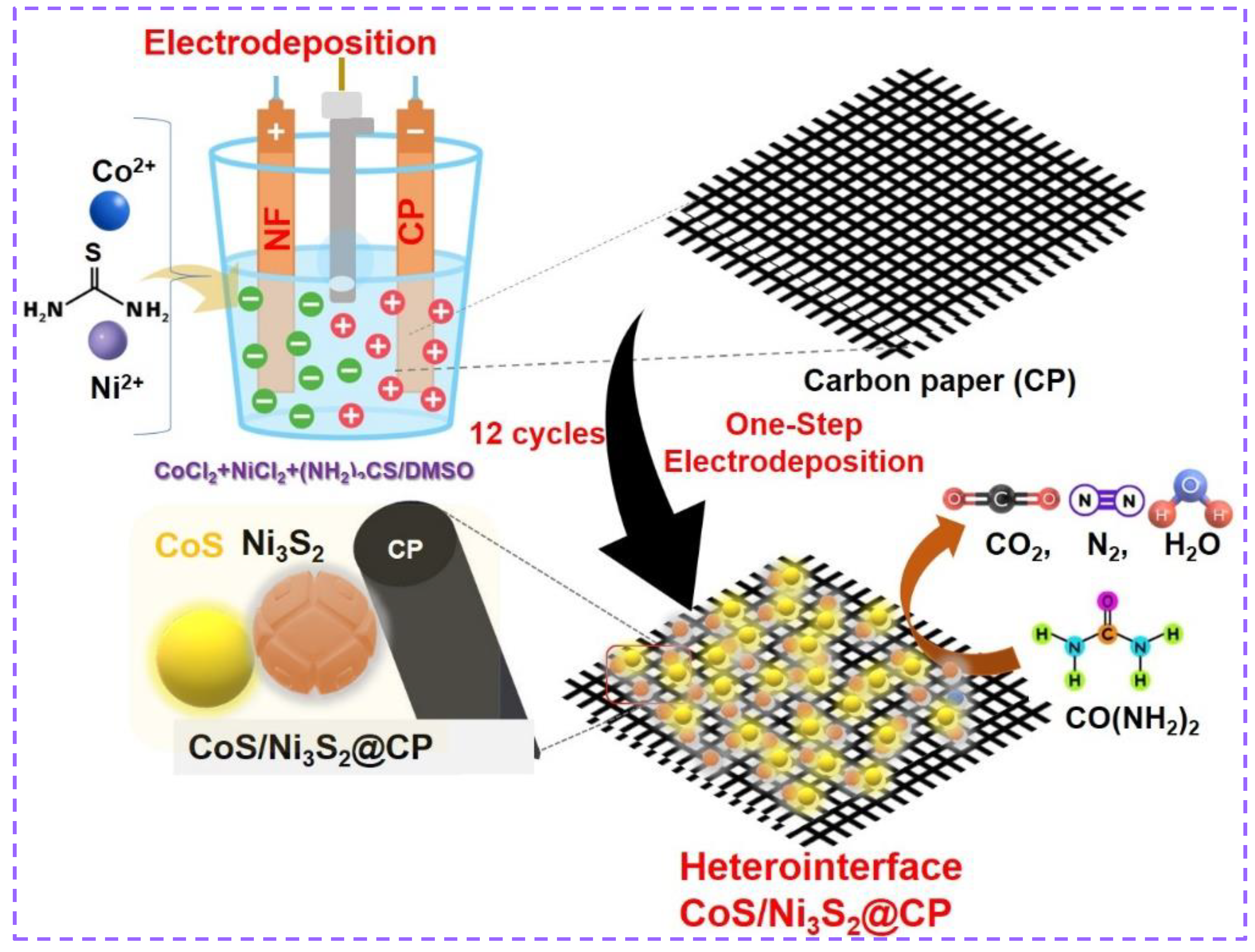
3.2. Electrodeposition of CoS/Ni3S2@CP NP Catalysts

A series of CoS@CP, Ni3S2@CP, and different ratios of CoS/Ni3S2@CP NP catalysts was synthesized by a facile electrodeposition on CP substrate in an airtight 3-electrode system. The classical 3-electrode assembly consisted of commercial CP, a Ag/AgCl (3.0 M KCl), and Ni foam (1.0 cm × 2.0 cm) as the working, reference, and counter electrodes, respectively. The CP is usually pre-treated with hot concentrated HNO3 for one minute. The Ni foam was also sonicated for 20 min with HCl (3.0 M), ethanol, and DI water to remove the oxide layer. To acquire a hydrophilic surface, the CP and Ni foam substrates were dried for 12 h at 60 °C. Typically, the working electrode is immersed in a 50 mL non-aqueous DMSO solution containing 0.035 M NiCl2, 0.0175 M CoCl2, and 0.5 M thiourea. Prior to electrochemical deposition cycles, nitrogen was bubbled continuously through the deposition solution for at least 30 min before deposition. Electrodeposition was conducted using cyclic voltammetry (CV) with consecutive linear scans between −1.25 and 0.2 V, while Ag/AgCl was scanned at 5 mV s−1 for 12 cycles at a reaction temperature of 60 °C to obtain a nanostructured CoS/Ni3S2@CP-b-anchored CP. Electrochemical depositions carried out at 8 cycles and 16 cycles are designated as CoS/Ni3S2@CP-a and CoS/Ni3S2@CP-c, respectively. After deposition, the fabricated CoS/Ni3S2@CP electrodes were gently rinsed with copious distilled water. Initially, the CoS/Ni3S2@CP materials were kept at room temperature overnight, followed by annealing at 350 °C for 30 min in N2 atmosphere at a rate of 5 °C/min. Before electrochemical measurements, the CoS/Ni3S2@CP electrodes were always stored under vacuum at room temperature. Alternatively, nickel sulfide (Ni3S2@CP) and cobalt sulfide (CoS@CP) can be electrodeposited without their respective precursors.

3.3. Characterizations

X-ray diffraction (XRD) data of the as-deposited catalyst were logged using MiniFlex-600 (Rigaku) with Cu Ka irradiation (40 KV, 15 mA). The field-emission scanning electron microscope (FE-SEM) photographs were recorded on JSM-7610F functioning at 15 KV equipped with an energy-dispersive X-ray spectroscopy (EDX) analyzer to identify catalyst morphology. An X-ray photoemission spectroscopy (XPS) study was conducted to observe surface chemical states by engaging an Escalab 250 spectrometer (Thermo-Fisher, Waltham, MA, USA).

3.4. Electrochemical Measurements

The electrochemical measurements, CV, and chronoamperometry (CA) were carried out using a biologic potentiostat commanded by EC-lab software 11.40 directly connected to a 3-electrode electrochemical cell. During the UOR test, three electrodes were employed, including a catalyst on the CP substrate’s conductivity side, a graphite counter electrode, and an Ag/AgCl reference electrode. For the UOR test, the three-electrode system involved as-deposited CoS/Ni3S2@CP-a, CoS/Ni3S2@CP-b, and CoS/Ni3S2@CP-c, Ni3S2@CP, and CoS@CP catalysts on a CP substrate’s conductivity side as working electrodes (1.0 cm2), a carbon graphite (1.0 cm2) as a counter electrode, and an Ag/AgCl reference electrode were employed during the measurements. The electrolyte was 1.0 M KOH in the presence of 0.33 M urea for UOR. All potentials were referred to as reversible hydrogen electrodes (RHEs). The electrochemical impedance spectra (EIS) were recorded between 200 and 10−2 kHz.

4. Conclusions

To sum up, a sequence of CoS-incorporated Ni3S2 catalysts supported on CP (CoS/Ni3S2@CP) with various CoS loadings was obtained by a one-step electrodeposition method and was applied as electrode materials for UOR. These electrocatalytic features demonstrated that cooperatively regulating the Ni3S2 electronic structure by CoS electrodeposition methods with optimized cycle results in enhanced UOR features of Ni3S2@CP surfaces in an alkaline media. Interfacial interactions at heterointerfaces influence charge transfer and electrocatalytic UOR kinetics. Accordingly, the developed CoS/Ni3S2@CP interfaces exhibit relatively low overpotential and enhanced UOR durability. By providing cost-effective synthesis and highly enhanced UOR features, CoS decorated Ni3S2 electrode materials may open up new avenues for highly active electrodes for UOR.

Supplementary Materials

The following supporting information can be downloaded at: https://www.mdpi.com/article/10.3390/catal14090570/s1, Figure S1: EDAX analysis of fabricated CoS/Ni3S2@CP-b catalysts fabricated using one-step electrodeposition approach; Figure S2: Cyclic voltammetric plots of CoS@CP, Ni3S2@CP, different ratios CoS/Ni3S2@CP NPs catalysts in a 1.0 M KOH solution; Figure S3: Surface features after stability tests. high resolution O1s XPS scan of CoS/Ni3S2@CP-b electrodes before and after durability tests.

Author Contributions

S.A.A.: conceptualization, data curation, formal analysis, investigation, writing—original draft, supervision, funding acquisition, project administration. P.A.: data curation, conceptualization, formal analysis, investigation, methodology, writing—review and editing. A.M.A.-M.: supervision. P.N.S.: data curation. A.R.: formal analysis, A.V.: investigation. J.H.: methodology. S.L.: data curation. P.S.P.: investigation. S.P.: formal analysis. R.A.: investigation. S.T.H.: formal analysis. All authors have read and agreed to the published version of the manuscript.

Funding

This project is sponsored by Prince Sattam Bin Abdulaziz University (PSAU) as part of funding for its SDG Roadmap Research Funding Programme project number PSAU-2023-SDG-12.

Data Availability Statement

All data generated or analyzed during this study are included in this published article (and its Supplementary Information Files).

Acknowledgments

This project is sponsored by Prince Sattam Bin Abdulaziz University (PSAU) as part of funding for its SDG Roadmap Research Funding Programme project number PSAU-2023-SDG-12.

Conflicts of Interest

The authors declare no conflicts of interest.

References

  1. Omer, A.M. Renewable Building Energy Systems and Passive Human Comfort Solutions. Renew. Sustain. Energy Rev. 2008, 12, 1562–1587. [Google Scholar] [CrossRef]
  2. Satyapal, S.; Petrovic, J.; Read, C.; Thomas, G.; Ordaz, G. The U.S. Department of Energy’ s National Hydrogen Storage Project: Progress towards Meeting Hydrogen-Powered Vehicle Requirements. Catal. Today 2007, 120, 246–256. [Google Scholar] [CrossRef]
  3. Barbir, F. PEM Electrolysis for Production of Hydrogen from Renewable Energy Sources. Sol. Energy 2005, 78, 661–669. [Google Scholar] [CrossRef]
  4. Christopher, K.; Dimitrios, R. A Review on Exergy Comparison of Hydrogen Production Methods from Renewable Energy Sources. Energy Environ. Sci. 2012, 5, 6640–6651. [Google Scholar] [CrossRef]
  5. Zhang, S. Design of Electrocatalysts for Oxygen- and Hydrogen-Involving Energy Conversion Reactions. Chem. Soc. Rev. 2023, 44, 2023–2576. [Google Scholar]
  6. Agyekum, E.B.; Nutakor, C.; Agwa, A.M.; Kamel, S.; Kame, S. A Critical Review of Renewable Hydrogen Production Methods: Factors Affecting Their Scale-up and Its Role in Future Energy Generation. Membranes 2022, 12, 173. [Google Scholar] [CrossRef] [PubMed]
  7. Amer, M.S.; Arunachalam, P.; Al-Mayouf, A.M.; Alsaleh, A.A.; Alshalwi, M.; Almutairi, Z.A. Effect of Iron and Vanadium Doping on Structural Phase Transition in Cobalt Diselenide Enabling Superior Oxygen/Hydrogen Electrocatalysis. ACS Appl. Energy Mater. 2023, 6, 11718–11731. [Google Scholar] [CrossRef]
  8. Zhang, W.; Cui, L.; Liu, J. Recent Advances in Cobalt-Based Electrocatalysts for Hydrogen and Oxygen Evolution Reactions. J. Alloys Compd. 2020, 821, 153542. [Google Scholar] [CrossRef]
  9. Li, H.; Shang, J.; Zhu, H.; Yang, Z.; Ai, Z.; Zhang, L. Oxygen Vacancy Structure Associated Photocatalytic Water Oxidation of BiOCl. ACS Catal. 2016, 6, 8276–8285. [Google Scholar] [CrossRef]
  10. Chen, T.; Qin, S.; Qian, M.; Dai, H.; Fu, Y.; Zhang, Y.; Ye, B.; Lin, Q.; Yang, Q. Defect-Rich Fe-Doped CoP Nanosheets as Efficient Oxygen Evolution Electrocatalysts. Energy Fuels 2021, 35, 10890–10897. [Google Scholar] [CrossRef]
  11. Zhu, X.; Dou, X.; Dai, J.; An, X.; Guo, Y.; Zhang, L.; Tao, S.; Zhao, J.; Chu, W.; Zeng, X.C.; et al. Metallic Nickel Hydroxide Nanosheets Give Superior Electrocatalytic Oxidation of Urea for Fuel Cells. Angew. Chem. Int. Ed. 2016, 55, 12465–12469. [Google Scholar] [CrossRef] [PubMed]
  12. Wei, S.; Wang, X.; Wang, J.; Sun, X.; Cui, L.; Yang, W.; Zheng, Y.; Liu, J. CoS 2 Nanoneedle Array on Ti Mesh: A Stable and Efficient Bifunctional Electrocatalyst for Urea-Assisted Electrolytic Hydrogen Production. Electrochim. Acta 2017, 246, 776–782. [Google Scholar] [CrossRef]
  13. Araujo, R.B.; Martín-Yerga, D.; Santos, E.C.d.; Cornell, A.; Pettersson, L.G.M. Elucidating the Role of Ni to Enhance the Methanol Oxidation Reaction on Pd Electrocatalysts. Electrochim. Acta 2020, 360, 136954. [Google Scholar] [CrossRef]
  14. Barakat, N.A.M.; Moustafa, H.M.; Nassar, M.M.; Abdelkareem, M.A.; Mahmoud, M.S.; Almajid, A.A.; Khalil, K.A. Distinct Influence for Carbon Nano-Morphology on the Activity and Optimum Metal Loading of Ni/C Composite Used for Ethanol Oxidation. Electrochim. Acta 2015, 182, 143–155. [Google Scholar] [CrossRef]
  15. Aladeemy, S.A.; Al-Mayouf, A.; Amer, M.; Alotaibi, N.; Weller, M.T.; Ghanem, M.A. Structure and Electrochemical Activity of Nickel Aluminium Fl Uoride Nanosheets during Urea Electro-Oxidation in an Alkaline Solution. RSC Adv. 2021, 11, 3190–3201. [Google Scholar] [CrossRef] [PubMed]
  16. Yang, L.; Li, X.; Chen, P.; Hou, Z. Selective Oxidation of Glycerol in a Base-Free Aqueous Solution: A Short Review. Chin. J. Catal. 2019, 40, 1020–1034. [Google Scholar] [CrossRef]
  17. Bamuqaddam, A.M.; Aladeemy, S.A.; Ghanem, M.A.; Al-Mayouf, A.M.; Alotaibi, N.H.; Marken, F. Foam Synthesis of Nickel/Nickel (II) Hydroxide Nanoflakes Using Double Templates of Surfactant Liquid Crystal and Hydrogen Bubbles: A High-Performance Catalyst for Methanol Electrooxidation in Alkaline Solution. Nanomaterials 2022, 12, 879. [Google Scholar] [CrossRef]
  18. Amer, M.S.; Arunachalam, P.; Alsalman, A.M.; Al-Mayouf, A.M.; Almutairi, Z.A.; Aladeemy, S.A.; Hezam, M. Facile Synthesis of Amorphous Nickel Iron Borate Grown on Carbon Paper as Stable Electrode Materials for Promoted Electrocatalytic Urea Oxidation. Catal. Today 2022, 397, 197–205. [Google Scholar] [CrossRef]
  19. Aladeemy, S.A.; Al-Mayouf, A.M.; Shaddad, M.N.; Amer, M.S.; Almutairi, N.K.; Ghanem, M.A.; Alotaibi, N.H.; Arunachalam, P. Electrooxidation of Urea in Alkaline Solution Using Nickel Hydroxide Activated Carbon Paper Electrodeposited from DMSO Solution. Catalysts 2021, 11, 102. [Google Scholar] [CrossRef]
  20. Arunachalam, P.; Nagai, K.; Amer, M.S.; Ghanem, M.A.; Ramalingam, R.J.; Al-mayouf, A.M. Recent Developments in the Use of Heterogeneous Semiconductor Photocatalyst Based Materials for A. Catalysts 2021, 11, 160. [Google Scholar] [CrossRef]
  21. Hu, X.; Zhu, J.; Li, J.; Wu, Q. Urea Electrooxidation: Current Development and Understanding of Ni-Based Catalysts. ChemElectroChem 2020, 7, 3211–3228. [Google Scholar] [CrossRef]
  22. Singh, R.K.; Schechter, A. Electroactivity of NiCr Catalysts for Urea Oxidation in Alkaline Electrolyte. ChemCatChem 2017, 9, 3374–3379. [Google Scholar] [CrossRef]
  23. Xie, J.; Qu, H.; Lei, F.; Peng, X.; Liu, W.; Gao, L.; Hao, P.; Cui, G.; Tang, B. Partially Amorphous Nickel-Iron Layered Double Hydroxide Nanosheet Arrays for Robust Bifunctional Electrocatalysis. J. Mater. Chem. A 2018, 6, 16121–16129. [Google Scholar] [CrossRef]
  24. Ye, K.; Wang, G.; Cao, D.; Wang, G. Recent Advances in the Electro-Oxidation of Urea for Direct Urea Fuel Cell and Urea Electrolysis. Top. Curr. Chem. 2018, 376, 42. [Google Scholar] [CrossRef]
  25. Urbańczyk, E.; Sowa, M.; Simka, W. Urea Removal from Aqueous Solutions—A Review. J. Appl. Electrochem. 2016, 46, 1011–1029. [Google Scholar] [CrossRef]
  26. Wang, G.; Wen, Z. Self-Supported Bimetallic Ni–Co Compound Electrodes for Urea- and Neutralization Energy-Assisted Electrolytic Hydrogen Production. Nanoscale 2018, 10, 21087–21095. [Google Scholar] [CrossRef]
  27. Al-Sulmi, W.A.; Ghanem, M.A.; Aladeemy, S.A.; Al-Mayouf, A.M.; Alotaibi, N.H. Chemical Deposition from a Liquid Crystal Template: A Highly Active Mesoporous Nickel Phosphate Electrocatalyst for Hydrogen Green Production via Urea. Arab. J. Chem. 2023, 16, 105266. [Google Scholar] [CrossRef]
  28. Amer, M.S.; Arunachalam, P.; Al-Mayouf, A.M.; AlSaleh, A.A.; Almutairi, Z.A. Bifunctional Vanadium Doped Mesoporous Co3O4 on Nickel Foam towards Highly Efficient Overall Urea and Water Splitting in the Alkaline Electrolyte. Environ. Res. 2023, 236, 116818. [Google Scholar] [CrossRef]
  29. Zhao, Z.; Wu, H.; He, H.; Xu, X.; Jin, Y. A High-Performance Binary Ni-Co Hydroxide-Based Water Oxidation Electrode with Three-Dimensional Coaxial Nanotube Array Structure. Adv. Funct. Mater. 2014, 24, 4698–4705. [Google Scholar] [CrossRef]
  30. Xia, W.; Mahmood, A.; Liang, Z.; Zou, R.; Guo, S. Earth-Abundant Nanomaterials for Oxygen Reduction. Angew. Chem. Int. Ed. 2016, 55, 2650–2676. [Google Scholar] [CrossRef]
  31. Wang, J.; Yue, X.; Yang, Y.; Sirisomboonchai, S.; Wang, P.; Ma, X.; Abudula, A.; Guan, G. Earth-Abundant Transition-Metal-Based Bifunctional Catalysts for Overall Electrochemical Water Splitting: A Review. J. Alloys Compd. 2020, 819, 153346. [Google Scholar] [CrossRef]
  32. Abdel Hameed, R.M.; Medany, S.S. Improved Electrocatalytic Kinetics of Nickel Hydroxide Nanoparticles on Vulcan XC-72R Carbon Black towards Alkaline Urea Oxidation Reaction. Int. J. Hydrogen Energy 2019, 44, 3636–3648. [Google Scholar] [CrossRef]
  33. Liu, M.; Jiao, Y.; Zhan, S.; Wang, H. Ni3S2 Nanowires Supported on Ni Foam as e Ffi Cient Bifunctional Electrocatalyst for Urea-Assisted Electrolytic Hydrogen Production. Catal. Today 2019, 355, 596–601. [Google Scholar] [CrossRef]
  34. Wang, X.; Liu, R.; Zhang, Y.; Zeng, L.; Liu, A. Hierarchical Ni 3 S 2 -NiOOH Hetero-Nanocomposite Grown on Nickel Foam as a Noble-Metal-Free Electrocatalyst for Hydrogen Evolution Reaction in Alkaline Electrolyte. Appl. Surf. Sci. 2018, 456, 164–173. [Google Scholar] [CrossRef]
  35. Zhou, W.; Zhao, J.; Guan, J.; Wu, M.; Li, G.R. Ni3S2 in Situ Grown on Ni Foam Coupled with Nitrogen-Doped Carbon Nanotubes as an Efficient Electrocatalyst for the Hydrogen Evolution Reaction in Alkaline Solution. ACS Omega 2019, 4, 20244–20251. [Google Scholar] [CrossRef]
  36. Sahoo, M.K.; Rao, G.R. Fabrication of NiCo2S4 Nanoball Embedded Nitrogen Doped Mesoporous Carbon on Nickel Foam as an Advanced Charge Storage Material. Electrochim. Acta 2018, 268, 139–149. [Google Scholar] [CrossRef]
  37. Yang, T.; Li, R.; Li, Z.; Gu, Z.; Wang, G.; Liu, J. Hybrid of NiCo2S4 and Nitrogen and Sulphur-Functionalized Multiple Graphene Aerogel for Application in Supercapacitors and Oxygen Reduction with Significant Electrochemical Synergy. Electrochim. Acta 2016, 211, 59–70. [Google Scholar]
  38. Ding, R.; Li, X.; Shi, W.; Xu, Q.; Wang, L.; Jiang, H.; Yang, Z.; Liu, E. Mesoporous Ni-P Nanocatalysts for Alkaline Urea Electrooxidation. Electrochim. Acta 2016, 222, 455–462. [Google Scholar] [CrossRef]
  39. Chebrolu, V.T.; Balakrishnan, B.; Aravindha Raja, S.; Cho, I.; Bak, J.S.; Kim, H.J. The One-Step Electrodeposition of Nickel Phosphide for Enhanced Supercapacitive Performance Using 3-Mercaptopropionic Acid. New J. Chem. 2020, 44, 7690–7697. [Google Scholar] [CrossRef]
  40. Liu, H.; Liu, Z.; Wang, F.; Feng, L. Efficient Catalysis of N Doped NiS/NiS2 Heterogeneous Structure. Chem. Eng. J. 2020, 397, 125507–125516. [Google Scholar] [CrossRef]
  41. Chen, T.; Wu, Q.; Li, F.; Zhong, R.; Chen, Z. Co2P−Ni3S2 Heterostructured Nanocrystals as Catalysts for Urea Electrooxidation and Urea-Assisted Water Splitting. Appl. Nano Mater. 2023, 6, 18364–18371. [Google Scholar] [CrossRef]
  42. Shit, S.; Chhetri, S.; Jang, W.; Murmu, N.C.; Koo, H.; Samanta, P.; Kuila, T. Cobalt Sulfide/Nickel Sulfide Heterostructure Directly Grown on Nickel Foam: An Efficient and Durable Electrocatalyst for Overall Water Splitting Application. ACS Appl. Mater. Interfaces 2018, 10, 27712–27722. [Google Scholar] [CrossRef] [PubMed]
  43. Li, X.; Han, G.Q.; Liu, Y.R.; Dong, B.; Hu, W.H.; Shang, X.; Chai, Y.M.; Liu, C.G. NiSe@NiOOH Core-Shell Hyacinth-like Nanostructures on Nickel Foam Synthesized by in Situ Electrochemical Oxidation as an Efficient Electrocatalyst for the Oxygen Evolution Reaction. ACS Appl. Mater. Interfaces 2016, 8, 20057–20066. [Google Scholar] [CrossRef]
  44. Li, Q.; Hou, Y.; Yin, J.; Xi, P. The Evolution of Hexagonal Cobalt Nanosheets for CO2 Electrochemical Reduction Reaction. Catalysts 2023, 13, 1384. [Google Scholar] [CrossRef]
  45. Kuznetsova, I.; Lebedeva, O.; Kultin, D.; Mashkin, M.; Kalmykov, K.; Kustov, L. Enhancing Efficiency of Nitrate Reduction to Ammonia by Fe and Co Nanoparticle-Based Bimetallic Electrocatalyst. Int. J. Mol. Sci. 2024, 25, 7089. [Google Scholar] [CrossRef] [PubMed]
  46. Xiang, D.; Bao, J.; Zhang, L.; Xin, P.; Yue, C.; Naseri, A.; Wang, H.; Huang, S.; Uvdal, K.; Hu, Z. Interfacial electronic structure modulations of Au@ CuS with defective Ni-doped CoS2 facilitates the electroreduction of N2 into NH3. Chem. Eng. J. 2024, 493, 152456. [Google Scholar] [CrossRef]
  47. Liu, N.; Guan, J. Core–Shell Co3O4@FeOx Catalysts for Efficient Oxygen Evolution Reaction. Mater. Today Energy 2021, 21, 100715. [Google Scholar] [CrossRef]
  48. Du, F.; Chen, Z.; Zhang, Y.; He, H.; Zhou, Y.; Li, T.; Zou, Z. Reduced-Graphene-Oxide-Loaded MoS2‡Ni3S2 Nanorod Arrays on Ni Foam as an Efficient and Stable Electrocatalyst for the Hydrogen Evolution Reaction. Electrochem. Commun. 2019, 99, 22–26. [Google Scholar] [CrossRef]
  49. Wang, C.H.; Yang, H.C.; Zhang, Y.J.; Wang, Q.B. NiFe Alloy Nanoparticles with hcp Crystal Structure Stimulate Superior Oxygen Evolution Reaction Electrocatalytic Activity. Angew. Chem. Int. Ed. 2019, 58, 6099–6103. [Google Scholar] [CrossRef]
  50. Wu, J.; Chen, J.; Yu, T.; Zhai, Z.; Zhu, Y.; Wu, X.; Yin, S. Boosting electrochemical kinetics of NiCo2 via MoO2 modification for biomass upgrading assisted hydrogen evolution. ACS Catal. 2023, 13, 13257–13266. [Google Scholar] [CrossRef]
  51. Wu, J.; Zhai, Z.; Yu, T.; Wu, X.; Huang, S.; Cao, W.; Jiang, Y.; Pei, J.; Yin, S. Tailoring the selective adsorption sites of NiMoO by Ni particles for biomass upgrading assisted hydrogen production. J. Energy Chem. 2023, 86, 480–489. [Google Scholar] [CrossRef]
  52. Yang, Y.; Zhang, K.; Lin, H.; Li, X.; Chan, H.C.; Yang, L.; Gao, Q. MoS2–Ni3S2 heteronanorods as efficient and stable bifunctional electrocatalysts for overall water splitting. ACS Catal. 2017, 7, 2357–2366. [Google Scholar] [CrossRef]
  53. Zhang, J.; Wang, T.; Pohl, D.; Rellinghaus, B.; Dong, R.; Liu, S.; Zhuang, X.; Feng, X. Interface engineering of MoS2/Ni3S2 heterostructures for highly enhanced electrochemical overall-water-splitting activity. Angew. Chem. 2016, 128, 6814–6819. [Google Scholar] [CrossRef]
  54. Zhang, Y.; Wang, D.; Lü, S.; Chen, Y.; Fan, H.; Wei, M.; Yang, L.; Yu, W.W.; Meng, X. CoO@CoS/Ni3S2 Hierarchical Nanostructure Arrays for High Performance Asymmetric SupercapacitorCoO@CoS/Ni3S2 Hierarchical Nanostructure Arrays for High Performance Asymmetric Supercapacitor. Appl. Surf. Sci. 2020, 532, 147438. [Google Scholar] [CrossRef]
  55. Hameed, R.M.A.; Medany, S.S. Influence of Support Material on the Electrocatalytic Activity of Nickel Oxide Nanoparticles for Urea Electro-Oxidation Reaction. J. Colloid Interface Sci. 2018, 513, 536–548. [Google Scholar] [CrossRef]
  56. Wang, D.; Botte, G.G. In Situ X-Ray Diffraction Study of Urea Electrolysis on Nickel Catalysts. ECS Electrochem. Lett. 2014, 3, 29–32. [Google Scholar] [CrossRef]
  57. Wang, L.; Saveleva, V.A.; Eslamibidgoli, M.J.; Antipin, D.; Bouillet, C.; Biswas, I.; Gago, A.S.; Hosseiny, S.S.; Gazdzicki, P.; Eikerling, M.H.; et al. Deciphering the Exceptional Performance of NiFe Hydroxide for the Oxygen Evolution Reaction in an Anion Exchange Membrane Electrolyzer. ACS Appl. Energy Mater. 2022, 5, 2221–2230. [Google Scholar] [CrossRef]
  58. Boggs, B.K.; King, R.L.; Botte, G.G. Urea Electrolysis: Direct Hydrogen Production from Urine. Chem. Commun. 2009, 2009, 4859–4861. [Google Scholar] [CrossRef] [PubMed]
  59. Vedharathinam, V.; Botte, G.G. Understanding the Electro-Catalytic Oxidation Mechanism of Urea on Nickel Electrodes in Alkaline Medium. Electrochim. Acta 2012, 81, 292–300. [Google Scholar] [CrossRef]
  60. Yi, P.; Song, Y.; Liu, Z.; Xie, P.; Liang, G.; Liu, R.; Chen, L.; Sun, J. Boosting Alkaline Urea Oxidation with a Nickel Sulfide/Cobalt Oxide Heterojunction Catalyst via Interface Engineering. Adv. Compos. Hybird Mater. 2023, 6, 228. [Google Scholar] [CrossRef]
  61. Li, F.; Cheng, J.; Zhang, D.; Fu, W.-F.; Chen, Y.; Wen, Z.; Lv, X.-J. Heteroporous MoS2/Ni3S2 towards Superior Electrocatalytic 491 Overall Urea Splitting. Chem. Commun. 2018, 54, 5181–5184. [Google Scholar] [CrossRef] [PubMed]
  62. Qian, G.; Chen, J.; Luo, L.; Zhang, H.; Chen, W.; Gao, Z.; Yin, S.; Tsiakaras, P. Novel Bifunctional V2O3Nanosheets Coupled with N-Doped-Carbon Encapsulated Ni Heterostructure for Enhanced Electrocatalytic Oxidation of Urea-Rich Wastewater. ACS Appl. Mater. Interfaces 2020, 12, 38061–38069. [Google Scholar] [CrossRef] [PubMed]
  63. Liu, Y.; Guan, J.; Chen, W.; Wu, Y.; Li, S.; Du, X.; Zhang, M. Nickel-Cobalt Derived Nanowires/Nanosheets as Electrocatalyst for Efficient H2 Generation via Urea Oxidation Reaction. J. Alloys Compd. 2021, 891, 161790. [Google Scholar] [CrossRef]
  64. Wang, Y.-T.; He, X.-F.; Chen, X.-M.; Zhang, Y.; Li, F.-T.; Zhou, Y.; Meng, C. Laser Synthesis of Cobalt-Doped Ni3S4-NiS/Ni as High-Efficiency Supercapacitor Electrode and Urea Oxidation Electrocatalyst. Appl. Surf. Sci. 2022, 596, 153600. [Google Scholar] [CrossRef]
Figure 1. Schematic preparation of heterostructure CoS/Ni3S2@CP catalysts via one-step electrodeposition.
Catalysts 14 00570 g001
Figure 2. Crystalline examinations. (a) XRD analysis of Ni3S2, CoS2, and different CoS/Ni3S2 catalysts grown on CP substrate, (b) XRD of CoS/Ni3S2@CP-b and corresponding bases.
Catalysts 14 00570 g002
Figure 3. Morphological examinations. SEM photographs of (a,b) CoS@CP, (c,d) Ni3S2@CP, and (e,f) CoS/Ni3S2@CP-b catalysts prepared by one-step electrodeposition approach.
Catalysts 14 00570 g003
Figure 4. Surface features of electrodes. Overall survey spectra of in CoS/Ni3S2@CP-b and Ni3S2@CP (a). High-resolution XPS profiles of Ni 2p (b), Co2p (c), S 2p (d) in CoS/Ni3S2@CP-b and Ni3S2@CP.
Catalysts 14 00570 g004
Figure 5. LSV plots of CoS@CP, Ni3S2@CP, different ratio CoS/Ni3S2@CP NP catalysts in a 1.0 M KOH solution without (a), and with (b) 0.33 M urea at 20 mV s−1, (c) LSV plots of CoS/Ni3S2@CP-b catalysts with and without urea, (d) estimated Tafel slopes for UOR in (b), and (e) anodic current density of as-deposited different ratios of CoS/Ni3S2@CP, Ni3S2@CP, and CoS@CP electrode materials at the potential of 1.5 V and 1.7 V vs. RHE.
Catalysts 14 00570 g005
Figure 6. Capacitance currents of (a) Ni3S2@CP, (b) CoS@CP, and (c) CoS/Ni3S2@CP-b catalysts, and (d) relationship between current density at −0.10 V versus scan rates: 30–110 mV s−1.
Catalysts 14 00570 g006
Figure 7. Long-term stability tests. (a) Time-dependent current density curves for CoS/Ni3S2@CP under an applied potential in 1 M KOH/0.33 M urea (b) high resolution Ni2p XPS scan, (c) Co 2p scan, and (d) S 2p scan of CoS/Ni3S2@CP-b electrodes before and after durability tests of UORs.
Catalysts 14 00570 g007
Figure 8. (a) EIS measurements of Ni3S2@CP, CoS @CP, and CoS/Ni3S2@CP-b catalysts at 1.45 V, and (b) Nyquist plots of as-deposited CoS@Ni3S2/CP-b sample at different potentials in 1.0 M KOH containing 0.33M urea; inset shows the equivalent circuit model of impedance data.
Catalysts 14 00570 g008
Table 1. Electrocatalytic UOR activity of CoS/Ni3S2@CP-b catalyst in alkaline media with that described in the literature relating to Ni-based electrocatalyst derived from CV analysis.
ElectrodesOverpotentialStabilityCurrent DensityElectrolyteTafel SlopeRef.
Ni3S2/Co3O4-NF1.288 V at 10 mA.cm−2100 h-- [60]
Co2P−Ni3S2-21.338 V at 10 mA.cm−2100 h100 mA.cm−2
at 1.5 V
1.0 M KOH + 0.5 M urea54.52 mV/dm[41]
MoS2/Ni3S2/Ni/NF1.33 V at 50 mA.cm−220 h200 mA.cm−2
at 1.35 V
1.0 M KOH + 0.33 M urea42 mV/dm[61]
Ni3S2/NF1.30 V at 10 mA.cm−2-120 mA.cm−2
at 1.7 V
1.0 M NaOH + 0.33 M urea46 mV/dm[33]
N-NiS/NiS2 1.38 V at 10 mA.cm−22 h120 mA.cm−2
at 1.5V
1.0 M KOH + 0.33 M urea28.34 mV/dm [40]
Ni@C−V2O3/NF 1.32 V at 10 mA.cm−250 h~500 mA.cm−2
at 1.4V
1.0 M KOH + 0.5 M urea41.22 mV/dm[62]
Ni1.5Co1.5-O/CC1.36 V at 10 mA.cm−2 ~100 mA.cm−2
at 1.5V
1.0 M KOH + 0.33 M urea59.52 mV/dm[63]
Co-doped Ni3S4-NiS/Ni1.350 V at 10 mA.cm−21000 cycle-1.0 M KOH + 0.33 M urea15.04 mV/dm[64]
CoS/Ni3S2@CP-b1.32 V at 10 mA.cm−214 h103.3 mA.cm−2
at 1.7 V
1 M KOH/0.33 M urea206 mV/dmThis work
Table 2. EIS parameters of CoS@CP, Ni3S2@CP, and different CoSx/Ni3S2@CP-b catalysts recorded through fitting EIS spectra measured at 450 mV.
Anodic MaterialsEIS Oarameters: R1 + Q2/R2 + Q3/R3
R1, ohmQ2, F.S(α − 1)R2, ohmQ3, F.S(α − 1)R3, ohm
CoS/Ni3S2@CP-b at 1.60 V3.9983.81 × 10−62.5020.19650.372
CoS/Ni3S2@CP-b at 1.50 V3.75859.07 × 10−62.3690.30971.246
CoS/Ni3S2@CP-b at 1.45 V3.770.26351.5462.02 × 10−62.42
CoS/Ni3S2@CP-b at 1.35 V3.370.1442 × 10−32.780.20014.081
Ni3S2@CP at 1.45 V3.970.29882.7950.37253.452
CoS@CP at 1.45 V4.860.18361.1480.12793.572
Disclaimer/Publisher’s Note: The statements, opinions and data contained in all publications are solely those of the individual author(s) and contributor(s) and not of MDPI and/or the editor(s). MDPI and/or the editor(s) disclaim responsibility for any injury to people or property resulting from any ideas, methods, instructions or products referred to in the content.

