Article

Nanorod Heterodimer-Shaped CuS/ZnxCd1−xS Heteronanocrystals with Z-Scheme Mechanism for Enhanced Photocatalysis

by
Lei Yang
,
Lihui Wang
,
Han Xiao
,
Di Luo
,
Jiangzhi Zi
,
Guisheng Li
and
Zichao Lian
*
School of Materials and Chemistry, University of Shanghai for Science and Technology, Shanghai 200093, China
*
Author to whom correspondence should be addressed.
Catalysts 2025, 15(3), 266; https://doi.org/10.3390/catal15030266
Submission received: 14 February 2025 / Revised: 4 March 2025 / Accepted: 10 March 2025 / Published: 12 March 2025
(This article belongs to the Special Issue Photocatalysis: Past, Present, and Future Outlook)

Abstract

:
The efficient separation of photo-generated electrons and holes is significantly importance for enhancing photocatalytic performance. However, there are few reports on precisely constructing interfaces within a single nanocrystal to investigate the mechanism of photoinduced carrier transfer. In this study, nanorod heterodimer-structured CuS/ZnxCd1−xS heteronanocrystals (CuS/ZnCdS HNCs) were successfully synthesized as a typical model to explore the photoinduced carrier dynamics in the photocatalytic hydrogen evolution reaction (HER). The CuS/ZnCdS HNCs exhibited a photocatalytic hydrogen evolution activity of 146 mmol h⁻1 g⁻1 under visible light irradiation, which is higher than most reported values. Moreover, after 15 h of hydrogen production cycling tests, we found that the material maintained high hydrogen production performance, indicating excellent stability. The CuS/ZnCdS HNCs achieved an apparent quantum yield (AQY) of 69.2% at 380 nm, which is the highest value reported so far for ZnCdS- or CuS-based photocatalysts. The remarkable activity and stability of the CuS/ZnCdS HNCs were attributed to the strong internal electric field (IEF) and Z-scheme mechanism, which facilitate efficient charge separation, as demonstrated by in situ X-ray photoelectron spectroscopy (XPS) and electron paramagnetic resonance (EPR) analyses. This discovery provides a new approach for constructing Z-scheme heterogeneous copper-based nanocomposites within nanocrystals and offers guidance for improving photocatalytic activity.

1. Introduction

With the development of human society and the progress of civilization, energy issues and environmental pollution have become increasingly severe. Against the backdrop of national carbon neutrality goals, photocatalytic technology has emerged as a significant means of addressing environmental pollution and ensuring a reliable energy supply [1]. Photocatalysis is widely recognized as an effective solution to these problems. Hydrogen is regarded as an ideal energy carrier for future applications. Therefore, the search for efficient and stable photocatalysts capable of converting solar energy into molecular hydrogen without generating pollutants is considered one of the primary candidate methods for utilizing this clean energy source. However, the low separation rate of photogenerated charges and the extremely short lifetime of semiconductor photogenerated carriers have limited the application of photocatalysis in the hydrogen evolution reaction (HER). Many researchers have explored various methods to address these issues and enhance photocatalytic efficiency in HER. Consequently, constructing heterostructures with multifunctionality within a single nanocrystal is a promising approach to significantly reduce the recombination rate of electrons and holes, facilitating the identification of photoinduced carrier information, and thereby improving the photocatalytic activity. Over the past few decades, various types of semiconductor photocatalysts have been synthesized, such as g-C3N4, ZnIn2S4, CdS [2], TiO2 [3], CuInS2 [4], and CuS (copper sulfide) [5], which have attracted extensive attention and application in the field of photocatalysis. Metal sulfide nanomaterials exhibit significant potential in HER and oxygen evolution reaction (OER) research due to their high catalytic activity [6], tunable electronic structure, and abundant active sites [7]. However, metal sulfide nanomaterials also face multiple challenges in HER and OER research, including long-term stability issues, the balance between catalytic activity and selectivity, unclear reaction mechanisms, and the development of multifunctional catalysts [8]. To address these challenges, this study adopts the following strategies: a composite structure was designed and implemented to enhance the chemical and structural stability of materials and increase active site density and selectivity and achieve long-term stability and balance between catalytic activity and selectivity; in situ characterization techniques (such as in situ XPS) were used to reveal unclear dynamic evolution mechanisms; composite materials based on bimetallic sulfides were designed as multifunctional catalysts. These strategies provide effective solutions for the practical application of metal sulfides in the field of clean energy. Studies have shown that CuS exhibits high light absorption capabilities in the visible and infrared regions. Its strong localized surface plasmon resonance (LSPR) effect enables efficient utilization of a larger portion of sunlight, thereby improving photocatalytic efficiency [9]. However, CuS also has some drawbacks, including photocorrosion and a high recombination rate of photoinduced carriers, which limit its photocatalytic activity [10]. These drawbacks can be partially mitigated by constructing heterostructured nanocrystals and surface modifications.
In recent years, ZnxCd1−xS (ZnCdS, zinc cadmium sulfide), as a ternary metal sulfide semiconductor, has demonstrated outstanding performance in photocatalytic applications due to its tunable bandgap by adjusting the Zn-to-Cd ratio [11] and strong light absorption capabilities in the ultraviolet and visible regions. Compared to single-component ZnS or CdS, ZnCdS has a broader light absorption range [12], excellent photogenerated charge separation ability, stable chemical properties, good controllability, and a simple synthesis method. Combining the advantages of both semiconductors within a single nanocrystal can significantly improve the separation rates of photoinduced electrons and holes, thereby extending the lifetime of photogenerated carriers and enhancing photocatalytic HER activity.
In this study, CuS/ZnCdS heteronanocrystals (HNCs) with a nanorod heterodimer structure were successfully synthesized through a continuous surface growth deposition method, using CuS nanoplates as seeds for the growth of ZnCdS. Under visible light irradiation, the photocatalytic HER rate of CuS/ZnCdS HNCs reached 146 mmol h⁻1 g⁻1, representing the highest reported value for a photocatalytic HER system. The results demonstrate that the quantum efficiency of the CuS/ZnCdS photocatalyst is 3650 times and 24.3 times higher than that of pristine CuS and ZnCdS, respectively. Additionally, as shown in Table S1, compared to previously reported CuS-based composite materials, the hydrogen production performance of CuS/ZnCdS is superior. According to Table S2, the apparent quantum yield (AQY) of CuS/ZnCdS without noble metal cocatalysts reaches 69.2% at 380 nm, which is significantly higher than that of previously reported ZnCdS-based composite materials. The enhancement in photocatalytic activity is attributed to the formation of an internal electric field (IEF) and a Z-scheme mechanism. In situ X-ray photoelectron spectroscopy (in situ XPS) and electron paramagnetic resonance (EPR) results provide strong evidence of the formation of a Z-scheme pathway at the interfaces within the CuS/ZnCdS nanocrystal, thereby improving photocatalytic HER performance. Furthermore, the innovative design of the rod-like material structure significantly enhances light utilization efficiency [13]. This study provides guidance for designing heterostructures within a single nanocrystal, facilitating the understanding of photocatalytic activity and photoinduced carrier transfer mechanisms.

2. Results and Discussion

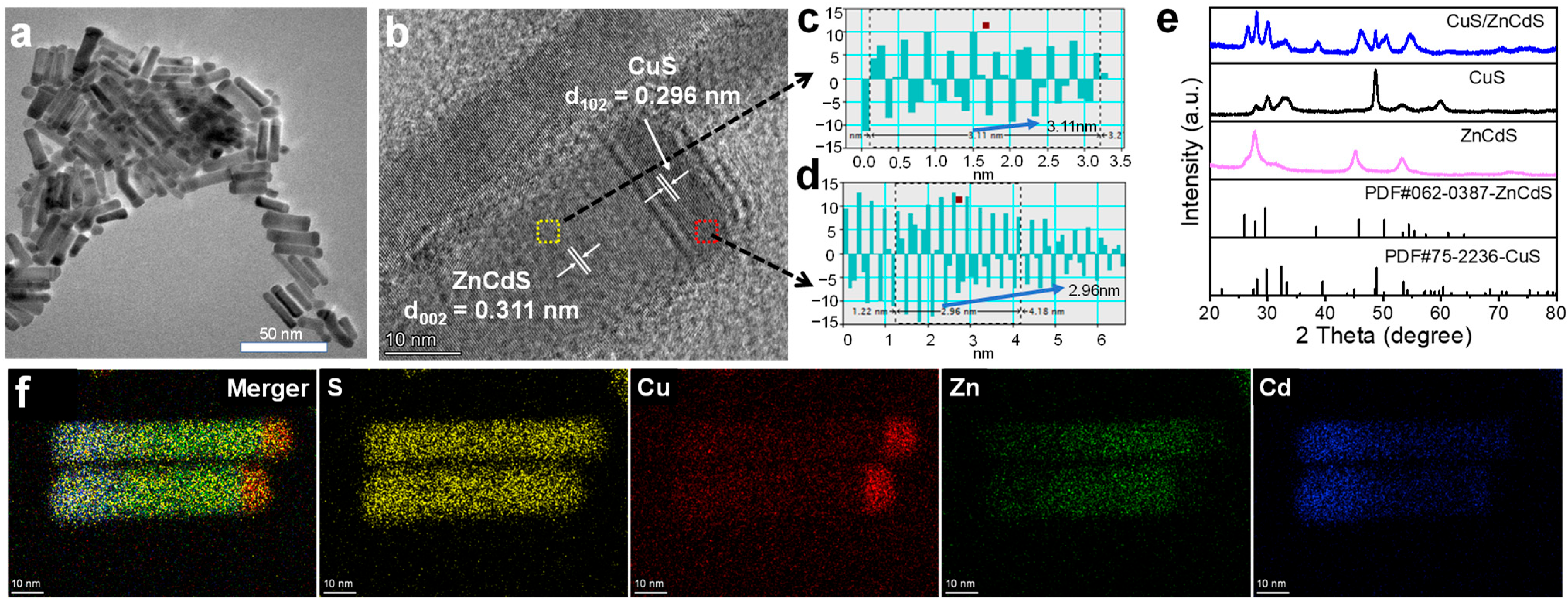
2.1. Structural Characterizations

The CuS/ZnCdS HNCs were synthesized successfully using the CuS nanoplate (size, thickness: 4.6 ± 0.1 nm, diameter: 13.2 ± 0.2 nm, as illustrated in Figures S2 and S3) as shown in Figure S1. Figure 1a shows the transmission electron microscopy (TEM) images of CuS/ZnCdS HNCs with diameters and lengths of 12 ± 0.6 nm and 55 ± 1.2 nm, respectively. (Figure S4). As shown in Figure 1b, the high-resolution TEM (HRTEM) image shows that the CuS/ZnCdS HNCs nanorods are composed of two phases, where the CuS component corresponds to the (102) crystal plane with a lattice spacing of 0.296 nm, and the other phase of ZnCdS to the (002) crystal plane with a lattice spacing of 0.311 nm (Figure 1c,d). This facilitates the epitaxial growth of ZnCdS nanoparticles layer by layer along the [100] direction of the CuS nanoplates, eventually forming a nanorod heterodimer-like structure. Through inductively coupled plasma emission spectrometry analysis, the weight ratio of the three elements Cd–Zn–Cu is 52.4:30:1.78 (see Table S3 for details). Furthermore, the X-ray diffraction (XRD) pattern of CuS/ZnCdS HNCs (Figure 1e) comprises both the hexagonal covellite CuS phase and the wurtzite ZnCdS phase. Furthermore, the high-angle annular dark-field scanning transmission electron microscopy (HAADF-STEM) energy-dispersive X-ray spectroscopy (EDS) mapping (Figure 1f) clearly shows the uniform distribution of each element: Cu is mainly concentrated at one end of the rod, Zn is evenly distributed throughout the rod except at the CuS end, Cd does not appear at the CuS end but is present throughout the rest of the rod, especially at the other end where it is in higher concentration, and S is uniformly distributed throughout the rod. All these observations directly confirm the formation of the heterodimer between CuS and ZnCdS phases of CuS/ZnCdS HNCs.

2.2. Optical Properties and Photoelectrochemical Measurements

Figure 2a shows the UV-Vis-NIR absorption spectra of CuS, ZnCdS, and CuS/ZnCdS HNCs. CuS shows a strong absorption peak at 1060 nm. Compared to the CuS, the absorption intensity in the near-infrared (NIR) region of CuS/ZnCdS HNCs is reduced, which is attributed to the wider bandgap of the ZnCdS phase. Furthermore, the shift in the plasmon resonance of CuS/ZnCdS HNPs relative to CuS NCs can be attributed to the disparate dielectric environments that prevail in the presence of ZnCdS [14,15,16]. Furthermore, the band gap (Eg) of CuS and ZnCdS can be determined from the Tauc plots in Figure 2b,c, using the following equation:
αhν = A (hν − E)n/2
The Eg values of pure ZnCdS and CuS were estimated to be 2.4 and 1.9 eV, respectively. As illustrated in Figure S5, the Mott–Schottky diagram demonstrates that the slope of ZnCdS is consistent with that of a typical n-type semiconductor. The flat potential of ZnCdS relative to the Ag/AgCl electrode is −0.51 V. The conduction band (CB) of ZnCdS relative to the normal hydrogen electrode (NHE, pH = 0) was determined as −0.11 eV. According to the findings of previous studies, the values of the CB and VB in CuS are −0.96 V and 0.94 V, respectively [17,18,19]. Thus, the band energy diagram of ZnCdS and CuS can be obtained, as illustrated in Figure 2d. In addition, to evaluate the charge separation and electrochemical properties of cu/ZnCdS HNCs in visible light, the transient photocurrent responses and electrochemical impedance spectroscopy (EIS) of CuS, ZnCdS, and CuS/ZnCdS HNCs were performed. As demonstrated in Figure 2e, the CuS/ZnCdS HNCs exhibit a photo-current density of 0.67 μA cm−2, which is 11.1 and 5.2 times that of CuS (0.06 μA cm−2) and ZnCdS (0.13 μA cm−2), respectively. The higher photocurrent density exhibited by CuS/ZnCdS HNC suggests that the formation of Z-type structures in these nanostructures contributes to accelerated photogenerated charge separation and transfer. As demonstrated in Figure 2f, the Nyquist arc radius of the CuS/ZnCdS HNC is reduced in comparison to that of CuS and ZnCdS, thereby indicating a lower resistance.

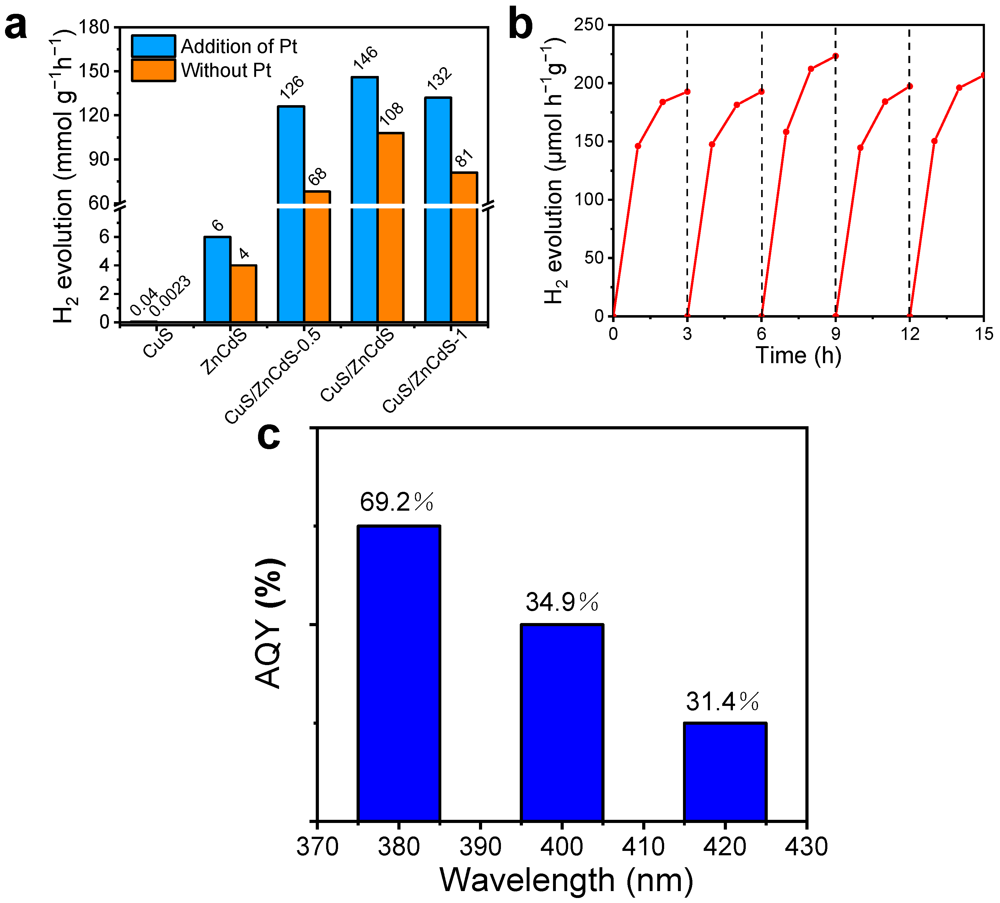
2.3. Photocatalytic Activity in HER for CuS/ZnCdS HNCs

To measure the photocatalytic activity of CuS/ZnCdS HNCs in the hydrogen evolution reaction (HER), we employed ligand exchange processes to render the samples hydrophilic [20], enabling them to dissolve easily in water for subsequent photocatalytic experiments. As shown in Figure 3a, in the absence of noble metal cocatalysts, the photocatalytic hydrogen evolution rate of CuS/ZnCdS HNCs reached 108 mmol h⁻1 g⁻1 under visible light irradiation using Na2S and Na2SO3 solutions as sacrificial agents. This result is higher than that of CuS (0.0023 mmol h⁻1 g⁻1) and ZnCdS (4.0 mmol h⁻1 g⁻1). When Pt was used as a cocatalyst, the hydrogen evolution rate of CuS/ZnCdS HNCs increased to 146 mmol h⁻1 g⁻1. This value is 3687 times higher than that of CuS (0.04 mmol h⁻1 g⁻1) and 24.4 times higher than that of ZnCdS (6 mmol h⁻1 g⁻1). As listed in Tables S1 and S2, this is also the highest value reported for CuS- or ZnCdS-based heterostructured nanomaterials. The remarkable hydrogen production performance of CuS/ZnCdS HNCs is closely related to the formation of a strong internal electric field (IEF) and Z-scheme pathways. These pathways effectively reduce the recombination of electron–hole pairs and promote efficient charge transfer. Additionally, the high specific surface area plays a significant role. The mesoporous structure of CuS/ZnCdS HNCs is closely correlated with its high specific surface area (see Figure S6). The specific surface area of CuS/ZnCdS HNCs is 49.6 m2 g⁻1, significantly higher than that of CuS (10.0 m2 g⁻1). Furthermore, stability is a critical consideration for photocatalysts. As shown in Figure 3b, CuS/ZnCdS HNCs underwent multiple cycles of long-term hydrogen production experiments under visible light irradiation (λ > 420 nm). After five cycles of 15 h each, CuS/ZnCdS HNCs maintained excellent stability. The slight decrease and fluctuations in the photocatalytic hydrogen evolution rate may be related to the consumption of sacrificial agents and measurement errors during the experiments. To further evaluate the stability of the material, XRD and TEM tests were conducted on the samples before and after the cyclic reactions, as shown in Figure S7. The CuS/ZnCdS heterojunction nanocomposites (HNCs) retained the same crystal structure and morphology, demonstrating exceptional stability. Additionally, we measured the wavelength-dependent apparent quantum yield (AQY) of CuS/ZnCdS HNCs, as shown in Figure 3c. Notably, at 380 nm, the AQY value of CuS/ZnCdS reached 69.2%, which is higher than that of previously reported photocatalysts listed in Tables S2 and S3. These results demonstrate that CuS/ZnCdS HNCs exhibit high photocatalytic activity and excellent stability in HER, supporting our proposed Z-scheme mechanism.

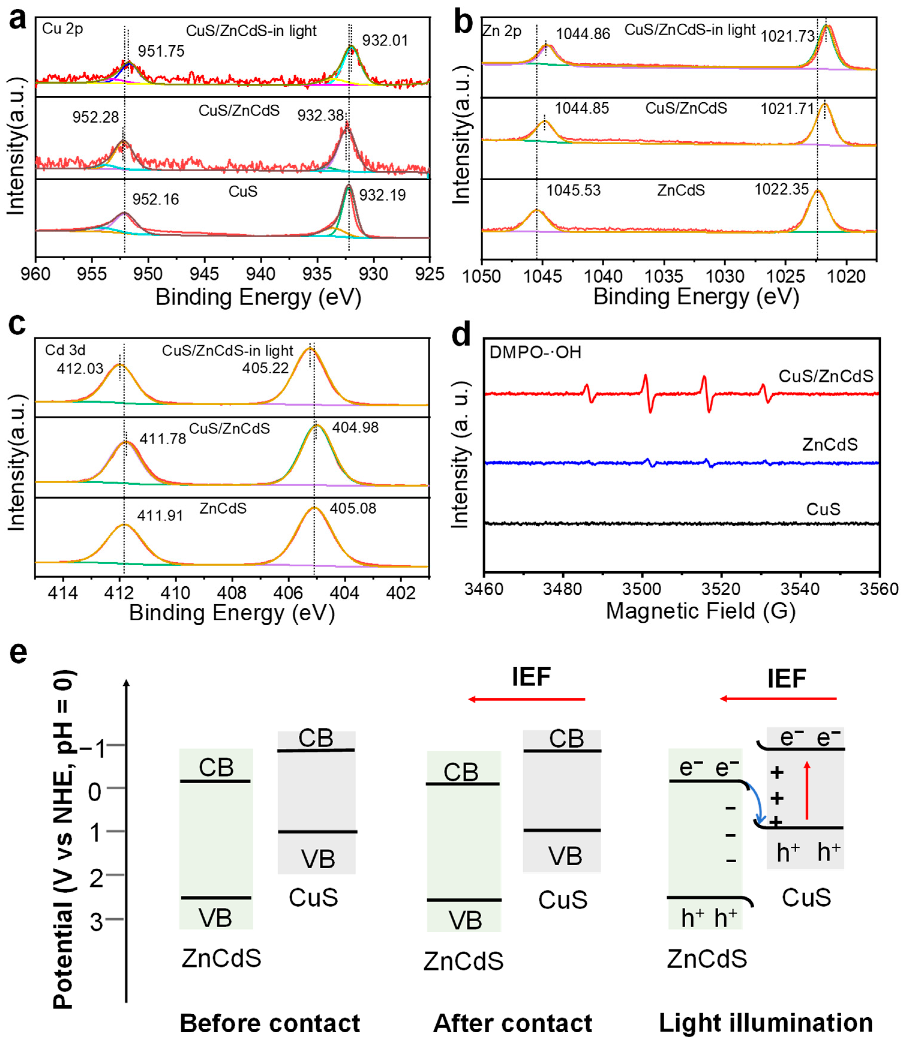
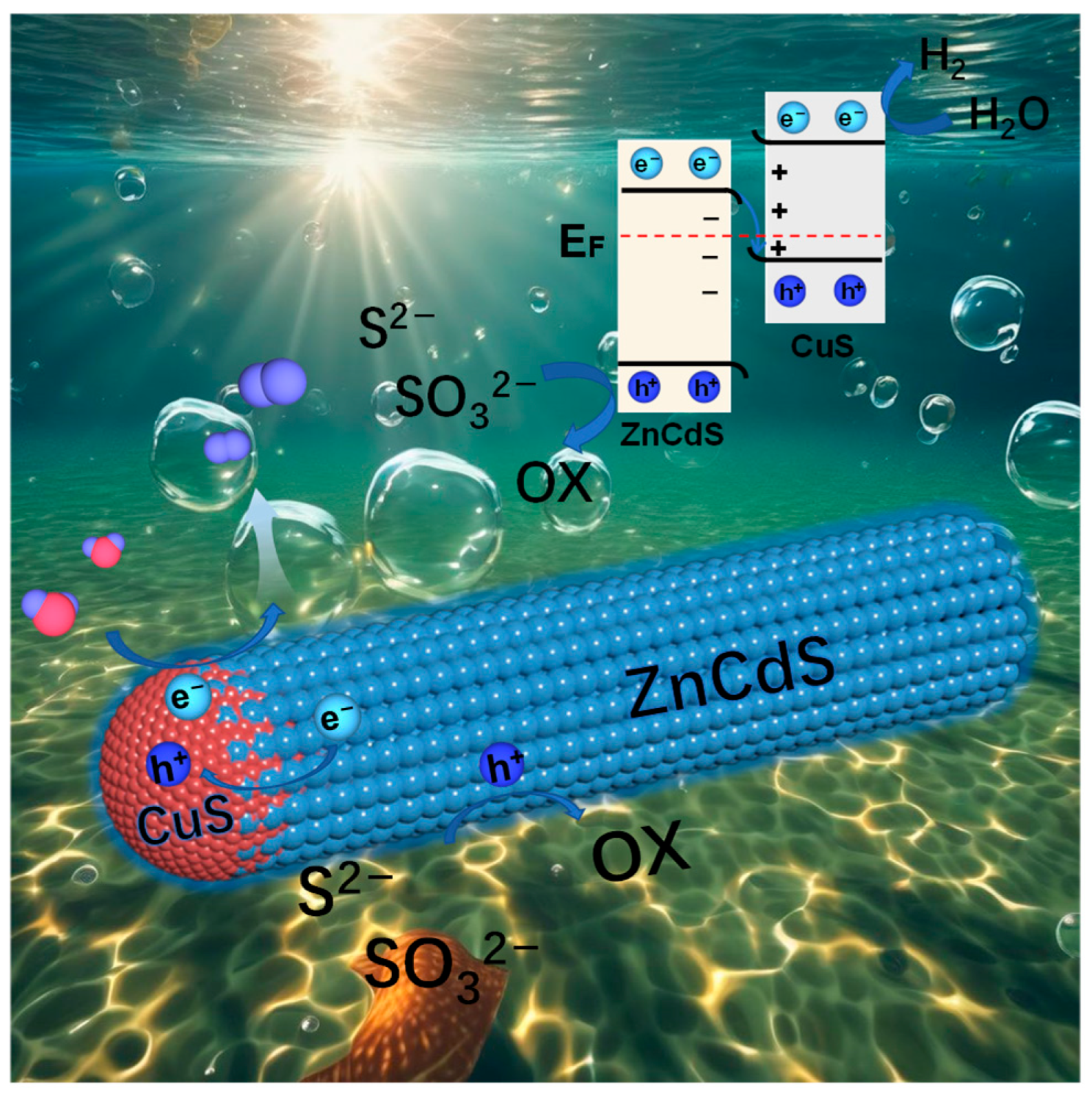
2.4. Understanding the Z-Scheme Mechanism in One CuS/ZnS Nanocrystal

To accurately analyze the surface chemical composition, the corresponding electronic states, and the direction of the photoinduced carrier transfer in CuS/ZnCdS HNCs. In situ X-ray photoelectron spectroscopy (XPS) and non-in situ X-ray photoelectron spectroscopy (XPS) measurements were performed. The full XPS spectrum of CuS/ZnCdS HNCs is presented in Figure S8, which shows the characteristic peaks of each element, thereby indicating that the CuS/ZnCdS HNCs were composed of CuS and ZnCdS phases. The binding energies were all calibrated from the c1s peak of 284.6 eV. The changes in the binding energy of elements can directly reflect the transfer of electrons between nanocrystals. As demonstrated in Figure 4a, for CuS NCs, the peak of Cu 2p at 932.19 is attributed to the 2p3/2 of Cu+ and the peak at 952.16 eV is attributed to the 2p1/2 orbitals of Cu+. In addition, the peaks at 934.4 eV of 2p3/2 orbitals and 2p1/2 at 954.8eV, are attributed to the Cu2+ in CuS, proving that there are two valence states of Cu in CuS NCs [21]. The peak of the Cu 2p3/2 orbital in CuS/ZnCdS HNCs is increased by about 0.19 eV compared to CuS NCs. On the contrary, as demonstrated in Figure 4b, the Zn 2p spectrum of ZnCdS is divided into two distinct peaks at 1022.4 and 1045.5 eV, representing Zn 2p3/2 and Zn 2p1/2, respectively. The binding energy of the Zn 2p orbital of CuS/ZnCdS HNCs is reduced by about 0.64 eV. In Figure 4c, the Cd 3d spectrum of ZnCdS is also divided into two distinct peaks, 405.08 and 411.91 eV, representing Cd 3d5/2 and Cd 3d3/2, respectively. The binding energy of the Cd 3d orbital of CuS/ZnCdS HNCs is reduced by about 0.1 eV. The results show that due to the increase in electron density around ZnCdS, electrons can be transferred from CuS to ZnCdS, resulting in a decrease in binding energy. It means that the strong built-in internal electric field is formed between CuS and ZnCdS in CuS/ZnCdS HNCs. Under visible light irradiation (λ > 420 nm), the direction of electron transfer in CuS/ZnCdS is opposite to that under dark conditions. The shifted peak binding energy of Cu 2p3/2 orbitals in CuS/ZnCdS is 0.53 eV lower than that under dark conditions, so it can be proved that CuS phase in CuS/ZnCdS obtains electrons under light conditions, then the direction of electron transfer is from the ZnCdS phase to the CuS phase in CuS/ZnCdS HNCs. After illumination, the binding energy peak position of Zn is 0.02 eV higher than that under dark conditions, and that of Cd is 0.24 eV higher than that under dark conditions, which means that ZnCdS in CuS/ZnCdS lose electrons after light irradiation. Therefore, in situ XPS results provide strong evidence for the movement direction of photogenerated carriers in CuS/ZnCdS under light conditions, favoring the formation of the Z-scheme mechanism at the interfaces in CuS/ZnCdS.
To verify the Z-type mechanism in CuS/ZnCdS heterojunctions, hydroxyl radical (-OH) detection was carried out using electron paramagnetic resonance (EPR) measurements. As shown in Figure 4d, under conditions of visible light irradiation, the signal strength of CuS/ZnCdS HNCs in EPR spectra was significantly enhanced, in contrast to ZnCdS with a weak signal of four symmetrical peaks (DMPO-•OH) and CuS with no signal. However, the signal intensity of CuS, ZnCdS and CuS/ZnCdS HNCs was almost undetectable under dark conditions. According to the band energy diagram, the high oxidation potential of VB in the ZnCdS phase is maintained to generate the signal of DMPO-•OH forming the Z-scheme heterojunction in CuS/ZnCdS, if it follows the conventional type-II mechanism, no signal will be present for the detection of •OH. For the Z-scheme mechanism, both the oxidation potential of VB in the ZnCdS phase and the reduction potential of CB in the CuS phase are kept, where the photoinduced electron in CB of ZnCdS phase can recombine with a photogenerated hole in the VB of CuS phase.
To reveal the Z-scheme mechanism in CuS/ZnCdS HNCs based on the in situ XPS and EPR results, a schematic illustration is presented in Figure 4e. When ZnCdS is in close contact with CuS, electrons will migrate from CuS to ZnCdS until the equilibrium of the Fermi level is achieved, which is consistent with the ex-situ XPS results. At this point, a strong internal electric field (IEF) is formed at the interface between CuS and ZnCdS, resulting in upward band bending of CuS and downward band bending of ZnCdS. The migration of electrons toward ZnCdS leads to the accumulation of electrons in ZnCdS, causing the interface to become negatively charged, while CuS becomes positively charged. As shown in Figure 5, when CuS/ZnCdS is irradiated by visible light, both the CuS and ZnCdS phases are excited. Studies have demonstrated that the photogenerated electrons in the conduction band (CB) of the ZnCdS phase can rapidly transfer to the valence band (VB) of the CuS phase and recombine with the photogenerated holes in CuS, forming the Z-scheme mechanism. Meanwhile, the holes in the VB of the ZnCdS phase and the photogenerated electrons in the CB of the CuS phase are preserved, facilitating efficient photocatalytic redox processes. Therefore, the enhanced photocatalytic performance of CuS/ZnCdS is attributed to the formation of Z-scheme heterojunctions between the two phases and the presence of a strong internal electric field (IEF), which promotes efficient charge separation.

3. Materials and Methods

3.1. Chemicals and Reagents

Zinc acetate dihydrate (Zn(OAc)2·2H2O, Aladdin), cadmium acetate dihydrate (Cd(OAc)2·2H2O, Aladdin), 1-dodecanethiol (DDT, TCI), oleic acid (OAc, Aladdin), Oleylamine (OAm, Aladdin), 1-octadecene (ODE, Aladdin), S powder, sodium sulfide nonahydrate (Na2S∙9H2O, Aladdin), sodium sulfite (Na2SO3, Aladdin), formamide (Aladdin), ammonium sulfide, trichloromethane (CHCl3, SCR), ethanol absolute (GENERAL-REAGENT), and hexane (GENERAL-REAGENT) were used as received without any additional purification or treatment. Deionized water was used in all experiments.

3.2. Preparation of Catalysts

3.2.1. Synthesis of CuS NCs

CuS NCs were used as the base material for the growth of ZnCdS. The synthetic processes are as follows: 1 mmol of copper acetate and 10 mL of oleylamine were degassed at 160 °C for 30 min. Subsequently, under nitrogen protection, a mixed solution containing 1.5 mmol of sulfur powder and 15 mL of 1-octadecene was rapidly added to the above liquid solution. The mixture was heated to 160 °C and stirred for 5 min. Then, the sample was cooled to room temperature, subjected to centrifugal separation using ethanol and hexane as the mobile phases, and finally dissolved in chloroform.

3.2.2. Synthesis of CuS/ZnCdS HNCs

In a typical seeded injection reaction, 0.75 mL of CuS solution was placed under vacuum to remove hexane, followed by redispersion with 3 mL of 1-dodecanethiol (1-DDT). Simultaneously, 0.25 mmol of cadmium acetate dihydrate (Cd(OAc)2·2H2O), 0.25 mmol of zinc acetate dihydrate (Zn(OAc)2·2H2O), and 13 mL of oleylamine were mixed in a three-neck flask and degassed at 110 °C for 30 min. Subsequently, under a nitrogen atmosphere, the mixture was heated to 250 °C, and the pre-prepared CuS nanocrystal solution was rapidly injected into the heated solution at this temperature. The reaction was allowed to proceed for 45 min. After the reaction was completed, the mixture was naturally cooled and purified using a hexane/ethanol mixture (1:2, v/v), followed by centrifugal separation. The resulting CuS/ZnCdS HNCs were redispersed in 5 mL of hexane. To investigate the effect of the Cu/Cd/Zn molar ratio on the photocatalytic hydrogen production performance of CuS/ZnCdS HNCs, additional samples were synthesized using the same experimental procedure by varying the volume of CuS (0.5 mL and 1.0 mL). Meanwhile, ZnCdS nanoparticles were synthesized using the same steps without the addition of CuS.

3.2.3. Preparation of Hydrophilic CuS/ZnCdS HNCs Samples

The preparation of water-soluble samples was carried out to enhance the hydrophilicity of CuS/ZnCdS HNCs. The synthesis process is as follows: 30 mg of photocatalyst was added to a 30 mL glass bottle containing 10 mL of chloroform solution [22]. Subsequently, 9.5 mL of formamide solution and 0.5 mL of (NH4)2S aqueous solution were added to the chloroform solution under vigorous stirring. The reaction was allowed to proceed for two hours, after which the mixture was subjected to centrifugal separation in the presence of ethanol. Finally, vacuum drying was performed.

3.3. Material Characterization

Transmission electron microscopy (TEM) and high-resolution electron microscopy (HRTEM) were performed using the HT7800 (Hitachi, Tokyo, Japan) at an acceleration voltage of 120 kV to obtain the morphology of the synthesized materials. X-ray diffraction (XRD) measurements were conducted using the Rigaku (Singapore) Dmax-3C Advance X-ray diffractometer at 40 kV and 30 mA with Cu Kα radiation (λ = 1.5406 Å) to study the structure of the synthesized materials. To determine the light absorption characteristics of different materials across various wavelength ranges, ultraviolet-visible absorption spectroscopy (UV-vis) was performed using the 1900i spectrophotometer (Shimadzu, Tokyo, Japan). X-ray photoelectron spectroscopy (XPS) measurements were carried out using the Thermo K-Alpha spectrometer with a 300 W Al Kα radiation source to analyze the elemental composition of the synthesized materials. In situ XPS measurements were conducted using the Thermo Scientific (Waltham, MA, USA) Escalab 250Xi at 14.8 kV and 1.6 A with a 150 W Al Kα radiation source under visible light irradiation (λ > 420 nm). Carbon (C 1s = 284.6 eV) was used as the reference for binding energy calibration, and the Advantage 5.9 software was employed for XPS peak fitting to investigate the electronic transfer behavior after the formation of composite materials, thereby further elucidating the type of heterojunction.

3.4. Electrochemical Measurements

To investigate the changes in photocurrent and electrochemical impedance after the formation of composite materials, photoelectrochemical (PEC) measurements were conducted. The testing procedure is as follows: in a 0.5 M Na2SO4 solution (pH = 6.8), a conventional three-electrode system and an electrochemical workstation were used. The counter electrode was platinum foil, the reference electrode was Ag/AgCl, and the working electrode was the photoanode [16,17]. The following solution was prepared: Nafion solution (10 μL, 5%), ethanol (500 μL), and photocatalyst (3 mg), of which 75 μL was deposited onto FTO conductive glass with an area of 1 cm2 to prepare the working electrode. The Mott–Schottky plot was employed to determine the flat band potential, and the flat band potential relative to the normal hydrogen electrode (NHE) was calculated using Equation (2).
Evs.NHE = Evs.Ag/AgCl + 0.1976 + 0.0592 × pH
Transient photocurrent spectra were measured in a 0.5 M Na2SO4 solution under 0.5 V visible light irradiation. Electrochemical impedance spectroscopy (EIS) measurements were carried out by applying an AC perturbation of 5 mV to the electrode at open-circuit voltage, with a frequency range of 10⁻2 to 105 Hz.

3.5. Hydrogen Production Performance Testing

The photocatalytic hydrogen evolution reaction (HER) activity was measured using a gas chromatograph GC-2014 (Shimadzu, Kyoto, Japan). In a 25 mL reactor, 5.0 mg of the photocatalyst was dispersed in an aqueous solution containing sacrificial agents (0.25 M Na2S, 0.35 M Na2SO3, 3 mL aqueous solution). The system was degassed, and the air in the reactor was repeatedly evacuated several times using a nitrogen cycle. The reactor was then filled with nitrogen to remove any residual air. Subsequently, the samples were exposed to a 300 W xenon lamp equipped with a UV filter (λ > 420 nm) for varying durations, with the lamp positioned 6 cm away from the photoreactor. Additionally, blank experiments without the samples were conducted to confirm that the thermal effect was negligible. To determine the amount of hydrogen produced, 0.2 mL of gas was extracted from the 25 mL reactor and injected into the gas chromatograph. The hydrogen peak area was read and converted to hydrogen production using a standard curve. The apparent quantum efficiency (AQY) was measured using different single-wavelength filters, and the light intensity was measured using a photoradiometer (Beijing Au-Light Instrument Co., Beijing, China, CEL-NP2000-2). The formula for AQY is as follows:
A Q Y = n u m b e r   o f   r e a c t e d   e l e c t r o n s n u m b e r   o f   i n c i d e n t   p h o t o n s × 100 % = n u m b e r   o f   e v o l u t e d   H 2   m o l e c u l e s n u m b e r   o f   i n c i d e n t   p h o t o n s × 100 %

4. Conclusions

In summary, we designed and synthesized CuS/ZnCdS heteronanocrystals (HNCs) to demonstrate photoinduced charge transfer within heterodimer nanocrystals. When using noble metal cocatalysts, the photocatalytic hydrogen evolution activity of CuS/ZnCdS HNCs under visible light irradiation reached 146 mmol h⁻1 g⁻1, which is higher than most reported values. Even in the absence of noble metal cocatalysts, the photocatalytic hydrogen production rate achieved 108 mmol g⁻1 h⁻1, demonstrating superior performance compared to previously reported CuS- and ZnCdS-based materials in the hydrogen evolution reaction (HER). Furthermore, the CuS/ZnCdS HNCs exhibited an apparent quantum yield (AQY) of 69.2% at 380 nm, the highest value reported so far for ZnCdS- or CuS-based photocatalysts. The remarkable hydrogen production performance and stability of CuS/ZnCdS HNCs are closely related to the formation of a strong internal electric field (IEF) and Z-scheme pathways. These pathways effectively reduce the recombination of electron–hole pairs and promote efficient charge transfer. Additionally, the rod-like structure significantly enhances light utilization efficiency. This study provides a new approach for developing heterostructured nanocrystals to achieve efficient solar-to-fuel conversion.

Supplementary Materials

The following supporting information can be downloaded at: https://www.mdpi.com/article/10.3390/catal15030266/s1, Figure S1. The schematic procedures of synthesizing CuS/ZnCdS. Figure S2. The TEM images of (a,b) CuS NCs and (c,d) ZnCdS. Figure S3. The diagram of the size distribution of (a) thickness, and (b) diameter of CuS NCs. Figure S4. (a) The diameter (b) and length size distribution diagram of CuS/ZnCdS HNCs. Figure S5. The Mott–Schottky plots of ZnCdS, CuS NCs, and CuS/ZnCdS nanorods. Figure S6. (a) Nitrogen adsorption–desorption isotherms and (b) pore-size distribution curves of CuS, and CuS/ZnCdS HNCs. Figure S7. XRD and TEM images of CuS/ZnCdS before and after cycling test in photocatalytic HER. Figure S8. The full XPS spectra of ZnCdS, CuS, and CuS/ZnCdS. Table S1. Photocatalytic activity of CuS-based photocatalytic materials in HER under visible light irradiation. Table S2. Summary of reported ZnCdS-based photocatalysts for photocatalytic hydrogen evolution. Table S3. The inductively coupled plasma optical emission spectroscopy (ICP-OES) data of CuS/ZnCdS HNCs. Refs. [23,24,25,26,27,28,29,30,31,32,33,34,35,36,37,38,39,40,41,42,43,44] are cited in the Supplementary Materials.

Author Contributions

L.Y.: synthesized the samples and performed the reactions, material characterization, electrochemical tests, and other characterizations, software and writing-original draft. L.W., H.X., D.L., J.Z. and G.L.: Investigation, Data curation, writing—reviewing and editing. Z.L.: conceived and designed the experiments and supervised the study, writing—reviewing and editing. All authors have read and agreed to the published version of the manuscript.

Funding

This work was supported by the National Natural Science Foundation of China (22109097).

Data Availability Statement

Data will be made available on request.

Acknowledgments

Thank you very much to the teachers and classmates who worked with me to complete this project. Many thanks to the National Natural Science Foundation project (22109097).

Conflicts of Interest

The authors declare no conflicts of interest.

References

  1. Lian, Z.; Wu, F.; Zi, J.; Li, G.; Wang, W.; Li, H. Infrared Light-Induced Anomalous Defect-Mediated Plasmonic Hot Electron Transfer for Enhanced Photocatalytic Hydrogen Evolution. J. Am. Chem. Soc. 2023, 145, 15482–15487. [Google Scholar] [CrossRef] [PubMed]
  2. Yao, L.; Sun, C.; Lin, H.; Li, G.; Lian, Z.; Song, R.; Zhuang, S.; Zhang, D. Electrospun Bi-decorated BixTiyOz/TiO2 flexible carbon nanofibers and their applications on degradation of organic pollutants under solar radiation. J. Mater. Sci. Technol. 2023, 150, 114–123. [Google Scholar] [CrossRef]
  3. Yang, Y.; Zhang, C.; Lai, C.; Zeng, G.; Huang, D.; Cheng, M.; Wang, J.; Chen, F.; Zhou, C.; Xiong, W. BiOX (X = Cl, Br, I) photocatalytic nanomaterials: Applications for fuels and environmental management. Adv. Colloid Interface Sci. 2018, 254, 76–93. [Google Scholar] [CrossRef] [PubMed]
  4. Liu, G.; Li, P.; Zhao, G.; Wang, X.; Kong, J.; Liu, H.; Zhang, H.; Chang, K.; Meng, X.; Kako, T.; et al. Promoting Active Species Generation by Plasmon-Induced Hot-Electron Excitation for Efficient Electrocatalytic Oxygen Evolution. J. Am. Chem. Soc. 2016, 138, 9128–9136. [Google Scholar] [CrossRef]
  5. Ma, P.; Zhang, X.; Wang, C.; Wang, Z.; Wang, K.; Feng, Y.; Wang, J.; Zhai, Y.; Deng, J.; Wang, L.; et al. Band alignment of homojunction by anchoring CN quantum dots on g-C3N4 (0D/2D) enhance photocatalytic hydrogen peroxide evolution. Appl. Catal. B Environ. 2022, 300, 120736. [Google Scholar] [CrossRef]
  6. Zhang, N.; Xing, Z.; Li, Z.; Zhou, W. Sulfur vacancy engineering of metal sulfide photocatalysts for solar energy conversion. Chem Catal. 2023, 3, 100375. [Google Scholar] [CrossRef]
  7. Mamiyev, Z.; Balayeva, N.O. PbS nanostructures: A review of recent advances. Mater. Today Sustain. 2023, 21, 100305. [Google Scholar] [CrossRef]
  8. Zheng, X.; Liu, Y.; Yang, Y.; Song, Y.; Deng, P.; Li, J.; Liu, W.; Shen, Y.; Tian, X. Recent Advances in Cadmium Sulfide-Based Photocatalysts for Photocatalytic Hydrogen Evolution. Renewables 2023, 1, 39–56. [Google Scholar] [CrossRef]
  9. Meng, A.; Zhang, L.; Cheng, B.; Yu, J. Dual Cocatalysts in TiO2 Photocatalysis. Adv. Mater. 2019, 31, 1807660. [Google Scholar] [CrossRef]
  10. Fan, H.-T.; Wu, Z.; Liu, K.-C.; Liu, W.-S. Fabrication of 3D CuS@ZnIn2S4 hierarchical nanocages with 2D/2D nanosheet subunits p-n heterojunctions for improved photocatalytic hydrogen evolution. Chem. Eng. J. 2022, 433, 134474. [Google Scholar] [CrossRef]
  11. Qiu, F.; Han, Z.; Peterson, J.J.; Odoi, M.Y.; Sowers, K.L.; Krauss, T.D. Photocatalytic Hydrogen Generation by CdSe/CdS Nanoparticles. Nano Lett. 2016, 16, 5347–5352. [Google Scholar] [CrossRef] [PubMed]
  12. Li, Y.; Zhao, Q.; Zhang, Y.; Li, Y.; Fan, L.; Li, F.-T.; Li, X. In-situ construction of sequential heterostructured CoS/CdS/CuS for building “electron-welcome zone” to enhance solar-to-hydrogen conversion. Appl. Catal. B Environ. 2022, 300, 120763. [Google Scholar] [CrossRef]
  13. Wang, L.-X.; Wang, Z.-Q.; Wang, L.; Wang, Z.; Yang, Q.; Zhu, Y.; Liu, W.; Fang, X.-Q.; Gong, Y.; Liu, X.; et al. CuSx-mediated two reaction systems enable biomimetic photocatalysis in CO2 reduction with visible light. J. Energy Chem. 2022, 65, 497–504. [Google Scholar] [CrossRef]
  14. Kuehnel, M.F.; Reisner, E. Solar Hydrogen Generation from Lignocellulose. Angew Chem. Int. Ed. 2018, 57, 3290–3296. [Google Scholar] [CrossRef]
  15. Wang, B.; Ding, Y.; Deng, Z.; Li, Z. Rational design of ternary NiS/CQDs/ZnIn2S4 nanocomposites as efficient noble-metal-free photocatalyst for hydrogen evolution under visible light. Chin. J. Catal. 2019, 40, 335–342. [Google Scholar] [CrossRef]
  16. Cui, C.; Xu, X.; Zhao, X.; Xi, N.; Li, M.; Wang, X.; Sang, Y.; Yu, X.; Liu, H.; Wang, J. Donor-acceptor covalent organic framework/ZnIn2S4 core-shell structure S-scheme heterostructure for efficient photocatalytic hydrogen evolution. Nano Energy 2024, 126, 109632. [Google Scholar] [CrossRef]
  17. Han, D.; Wu, C.; Zhang, Q.; Wei, S.; Qi, X.; Zhao, Y.; Chen, Y.; Chen, L.; Xiao, L.; Zhao, Z. Solution-Processed Cu9S5 as a Hole Transport Layer for Efficient and Stable Perovskite Solar Cells. ACS Appl. Mater. Interfaces 2018, 10, 31535–31540. [Google Scholar] [CrossRef]
  18. Rameshbabu, R.; Ravi, P.; Sathish, M. Cauliflower-like CuS/ZnS nanocomposites decorated g-C3N4 nanosheets as noble metal-free photocatalyst for superior photocatalytic water splitting. Chem. Eng. J. 2019, 360, 1277–1286. [Google Scholar] [CrossRef]
  19. Lv, S.; Yuan, H.; Xing, M.; Li, K.; Pak, Y.L.; Gao, X.; Zhang, D.; Mou, H.; Song, J. Surface vacancy engineering powered reverse cation exchange in preparing CuZnS hollow nanoboxs for efficient photocatalytic hydrogen evolution. Chem. Eng. J. 2024, 152025. [Google Scholar] [CrossRef]
  20. Zhang, M.-J.; Lin, Q.X.; Yang, X.Y.; Mei, Z.W.; Liang, J.; Lin, Y.; Pan, F. Novel p-Type Conductive Semiconductor Nanocrystalline Film as the Back Electrode for High-Performance Thin Film Solar Cells. Nano Lett. 2016, 16, 1218–1223. [Google Scholar] [CrossRef]
  21. Lian, Z.; Kobayashi, Y.; Vequizo, J.J.M.; Ranasinghe, C.S.K.; Yamakata, A.; Nagai, T.; Kimoto, K.; Kobayashi, K.; Tanaka, K.; Teranishi, T.; et al. Harnessing infrared solar energy with plasmonic energy upconversion. Nat. Sustain. 2022, 5, 1092–1099. [Google Scholar] [CrossRef]
  22. Lian, Z.; Sakamoto, M.; Matsunaga, H.; Vequizo, J.J.M.; Yamakata, A.; Haruta, M.; Kurata, H.; Ota, W.; Sato, T.; Teranishi, T. Near infrared light induced plasmonic hot hole transfer at a nano-heterointerface. Nat. Commun. 2018, 9, 2314. [Google Scholar] [CrossRef] [PubMed]
  23. Xu, Y.; Zhou, Z.; Yu, P.; Wang, Y. Al-doped CuS/Znln2S4 forming Schottky junction induced electron trap centers for photocatalytic overall water splitting. Chem. Eng. J. 2023, 470, 144275. [Google Scholar] [CrossRef]
  24. Chang, C.-J.; Wei, Y.-H.; Kuo, W.-S. Free-standing CuS–ZnS decorated carbon nanotube films as immobilized photocatalysts for hydrogen production. Int. J. Hydrogen Energy 2019, 44, 30553–30562. [Google Scholar] [CrossRef]
  25. Fan, H.; Sun, S.; Ba, J.; Cheng, H.; Xu, C.; Wang, Y.; Li, J.; Fang, H.; Li, M.; Fan, D. Constructing V2O5/CdS/CuS multi-level heterojunction for efficient photocatalytic hydrogen evolution. Int. J. Hydrogen Energy 2023, 48, 29593–29603. [Google Scholar] [CrossRef]
  26. Hong, E.; Kim, D.; Kim, J.H. Heterostructured metal sulfide (ZnS–CuS–CdS) photocatalyst for high electron utilization in hydrogen production from solar water splitting. J. Ind. Eng. Chem. 2014, 20, 3869–3874. [Google Scholar] [CrossRef]
  27. Vempuluru, N.R.; Krishnan, C.K.; Parnapalli, R.; Velusamy, J.; Marappan, S.; Pitchaimuthu, S.; Murikinati, M.; Venkatakrishnan, S.M. Solar hydrogen generation from organic substance using earth-abundant CuS–NiO heterojunction semiconductor photocatalyst. Ceram. Int. 2021, 47, 10206–10215. [Google Scholar] [CrossRef]
  28. Yu, Z.; Luan, X.; Xiao, H.; Yang, Y.; Luo, D.; Zi, J.; Lian, Z. Gemstone nanoflower-shaped ZnIn2S4/CuS heterojunction with ultralong lifetime of photoinduced carriers for photocatalytic hydrogen evolution. Appl. Catal. B-Environ. 2024, 347, 123702. [Google Scholar] [CrossRef]
  29. Wang, Y.; Jin, H.; Li, Y.; Fang, J.; Chen, C. Ce-based organic framework enhanced the hydrogen evolution ability of ZnCdS photocatalyst. Int. J. Hydrogen Energy 2022, 47, 962–970. [Google Scholar] [CrossRef]
  30. Zheng, C.; Jiang, G.; Jin, Z. ZnCdS/NiAl hydrotalcite S-scheme heterojunction for efficient photocatalytic hydrogen evolution. Int. J. Hydrogen Energy 2022, 47, 292–304. [Google Scholar] [CrossRef]
  31. Chen, J.M.; Shen, Z.R.; Lv, S.M.; Shen, K.; Wu, R.F.; Jiang, X.F.; Fan, T.; Chen, J.Y.; Li, Y.W. Fabricating sandwich-shelled ZnCdS/ZnO/ZnCdS dodecahedral cages with “one stone” as Z-scheme photocatalysts for highly efficient hydrogen production. J. Mater. Chem. A 2018, 6, 19631–19642. [Google Scholar] [CrossRef]
  32. Zhang, T.; Meng, F.; Gao, M.; Wei, J.; Lim, K.J.H.; Lim, K.H.; Chirawatkul, P.; Wong, A.S.W.; Kawi, S.; Ho, G.W. Porous Host–Guest MOF-Semiconductor Hybrid with Multisites Heterojunctions and Modulable Electronic Band for Selective Photocatalytic CO2 Conversion and H2 Evolution. Small 2023, 19, 2301121. [Google Scholar] [CrossRef] [PubMed]
  33. Li, H.; Tao, S.; Wan, S.; Qiu, G.; Long, Q.; Yu, J.; Cao, S. S-scheme heterojunction of ZnCdS nanospheres and dibenzothiophene modified graphite carbon nitride for enhanced H2 production. Chin. J. Catal. 2023, 46, 167–176. [Google Scholar] [CrossRef]
  34. Jin, S.; Wu, J.B.; Jiang, J.Z.; Wang, R.G.; Zhou, B.X.; Wang, L.B.; Hu, Q.K.; Zhou, A.G. Boosting the photocatalytic performance of CdxZn1-xSfor H2 production by Mo2C MXene with large interlayer distance. J. Mater. Chem. A 2023, 11, 5851–5863. [Google Scholar] [CrossRef]
  35. Zhang, J.; Li, L.; Du, M.; Cui, Y.; Li, Y.; Yan, W.; Huang, H.; Li, X.A.; Zhu, X. Single-Atom Phosphorus Defects Decorated CoP Cocatalyst Boosts Photocatalytic Hydrogen Generation Performance of Cd0.5Zn0.5S by Directed Separating the Photogenerated Carriers. Small 2023, 19, 2300402. [Google Scholar] [CrossRef]
  36. Lei, Y.; Zhang, Y.; Li, Z.; Xu, S.; Huang, J.; Ng, K.H.; Lai, Y. Molybdenum sulfide cocatalyst activation upon photodeposition of cobalt for improved photocatalytic hydrogen production activity of ZnCdS. Chem. Eng. J. 2021, 425, 131478. [Google Scholar] [CrossRef]
  37. Ahmad, M.; Quan, X.; Chen, S.; Yu, H.; Zeng, Z. Operating redox couple transport mechanism for enhancing photocatalytic H2 generation of Pt and CrOx-decorated ZnCdS nanocrystals. Appl. Catal. B-Environ. 2021, 283, 119601. [Google Scholar] [CrossRef]
  38. Zhang, C.; Liu, H.; Wang, W.; Qian, H.; Cheng, S.; Wang, Y.; Zha, Z.; Zhong, Y.; Hu, Y. Scalable fabrication of ZnxCd1-xS double-shell hollow nanospheres for highly efficient hydrogen production. Appl. Catal. B-Environ 2018, 239, 309–316. [Google Scholar] [CrossRef]
  39. Chen, J.M.; Chen, J.Y.; Li, Y.W. Hollow ZnCdS dodecahedral cages for highly efficient visible-light-driven hydrogen generation. J. Mater. Chem. A 2017, 5, 24116–24125. [Google Scholar] [CrossRef]
  40. Zhao, X.; Feng, J.; Liu, J.; Shi, W.; Yang, G.; Wang, G.-C.; Cheng, P. An Efficient, Visible-Light-Driven, Hydrogen Evolution Catalyst NiS/ZnCd1−xS Nanocrystal Derived from a Metal-Organic Framework. Angew. Chem. Int. Ed. 2018, 57, 9790–9794. [Google Scholar] [CrossRef]
  41. Dai, D.; Xu, H.; Ge, L.; Han, C.; Gao, Y.; Li, S.; Lu, Y. In-situ synthesis of CoP co-catalyst decorated Zn0.5Cd0.5S photocatalysts with enhanced photocatalytic hydrogen production activity under visible light irradiation. Appl. Catal. B-Environ. 2017, 217, 429–436. [Google Scholar] [CrossRef]
  42. Huang, W.; Su, C.; Zhu, C.; Bo, T.; Zuo, S.; Zhou, W.; Ren, Y.; Zhang, Y.; Zhang, J.; Rueping, M.; et al. Isolated Electron Trap-Induced Charge Accumulation for Efficient Photocatalytic Hydrogen Production. Angew. Chem. Int. Ed. 2023, 62, e202304634. [Google Scholar] [CrossRef]
  43. Chen, Y.; Zhao, S.; Wang, X.; Peng, Q.; Lin, R.; Wang, Y.; Shen, R.; Cao, X.; Zhang, L.; Zhou, G.; et al. Synergetic Integration of Cu1.94S–ZnxCd1–xS Heteronanorods for Enhanced Visible-Light-Driven Photocatalytic Hydrogen Production. J. Am. Chem. Soc. 2016, 138, 4286–4289. [Google Scholar] [CrossRef] [PubMed]
  44. Wang, L.; Xiao, H.; Yang, L.; Li, J.; Zi, J.; Lian, Z. Hollow Nanobox-Shaped Cu2-xS@ZnxCd1-xS Heterojunction by Light Multireflection with Z-Scheme Mechanism for Enhanced Photocatalytic Hydrogen Production. Adv. Funct. Mater 2025, 35, 2416358. [Google Scholar] [CrossRef]
Figure 1. (a) Representative transmission electron microscopy (TEM) images of CuS/ZnCdS HNCs. (b) High-resolution transmission electron microscopy (HRTEM) image of a single CuS/ZnCdS HNCs. (c,d) The column intensity to determine the lattice spacings of ZnCdS and CuS in (b). (e) XRD patterns of CuS, ZnCdS, and CuS/ZnCdS HNCs (f) HAADF-STEM-EDS elemental mapping images of the CuS/ZnCdS HNCs.
Catalysts 15 00266 g001
Figure 2. (a) UV-vis-NIR absorption spectra of CuS, ZnCdS, and CuS/ZnCdS HNCs. Tauc plots to estimate bandgaps of ZnCdS (b) and CuS (c). (d) The energy band level diagrams of CuS and ZnCdS. CB, conduction band; VB, valence band. (e) The transient photocurrent response spectra in the light on–off processes (0.3 V vs. Ag/AgCl) under the visible light irradiation (λ > 420 nm) with 40 slight on/off cycles of ZnCdS, CuS, and CuS/ZnCdS HNCs. (f) The Nyquist plots of ZnCdS, CuS, and CuS/ZnCdS HNCs.
Catalysts 15 00266 g002
Figure 3. (a) Comparison of the photocatalytic activity of hydrogen evolution rate for CuS, ZnCdS, and CuS/ZnCdS HNCs with or without Pt cocatalysts (the amount of CuS added is 0.5 mL, 0.75 mL (in this paper), and 1 mL, respectively). Under light irradiation (>420 nm) irradiation using the sacrificial agent (Na2S-Na2SO3 aqueous solution). (b) Recyclability testing of the CuS/ZnCdS HNCs for photocatalytic activity in the HER. (c) Apparent quantum yields (AQY s) of CuS/ZnCdS HNCs at different single wavelengths under the same conditions.
Catalysts 15 00266 g003
Figure 4. In situ and ex situ XPS spectra of CuS, ZnCdS, and CuS/ZnCdS HNCs in (a) Cu 2p orbitals, (b) Zn 2p orbitals, and (c) Cd 3d orbitals. (d) The electron paramagnetic resonance (EPR) signal of DMPO-•OH in CuS, ZnCdS, and CuS/ZnCdS (aqueous solution) under visible light irradiation for 10 min. (e) The schematic illustration of the Z-scheme mechanism of CuS/ZnCdS HNCs under visible light irradiation.
Catalysts 15 00266 g004
Figure 5. Schematic diagram of the material structure and reaction mechanism.
Catalysts 15 00266 g005
Disclaimer/Publisher’s Note: The statements, opinions and data contained in all publications are solely those of the individual author(s) and contributor(s) and not of MDPI and/or the editor(s). MDPI and/or the editor(s) disclaim responsibility for any injury to people or property resulting from any ideas, methods, instructions or products referred to in the content.

