Article

Regulating the Structures of Carbon Cloth and Carbon Nanotubes to Boost the Positive Electrode Reaction of Vanadium Redox Flow Batteries

1
School of Textile and Material Engineering, Dalian Polytechnic University, Dalian 116034, China
2
School of Electrical Engineering and Automation, Harbin Institute of Technology, Harbin 150006, China
3
Faculty of Science and Technology, Beijing Normal University-Hong Kong Baptist University United International College, Zhuhai 519088, China
*
Author to whom correspondence should be addressed.
These authors contributed equally to this work.
Catalysts 2025, 15(4), 345; https://doi.org/10.3390/catal15040345
Submission received: 23 February 2025 / Revised: 23 March 2025 / Accepted: 27 March 2025 / Published: 1 April 2025
(This article belongs to the Section Catalysis for Sustainable Energy)

Abstract

:
Considering the various morphologies of carbon nanotubes (CNTs), it is expected to solve the contradiction between concentration polarization and electrochemical polarization in vanadium redox flow batteries (VRFBs). This paper investigates the structural evolution of CNTs grown on the surface of thermally oxidized carbon cloth (TCC) and their impact on the performance of VRFBs. The morphological results indicate that thermal oxidation treatment forms pores on the surface of the TCC, providing nucleation sites for CNT growth. Spiral-shaped CNTs (TCC@s-CNTs) were formed in a short growth time (1 h), and their high defect density originated from the non-steady-state supply of carbon sources and the dynamic behavior of the catalyst. While 3 h of growth forms a network structure (TCC@n-CNT), the van der Waals force drives the self-assembly of its three-dimensional network. Although the TCC@s-CNT exhibits high catalytic activity due to its high defect density and edge active sites, the performance of VRFBs is more dependent on the three-dimensional conductive network of the TCC@n-CNT. At 240 mA/cm2, the energy efficiency (EE) of a VRFB assembled with the TCC@n-CNT reaches 71%, and the capacity retention rate is 15% higher than that of the TCC@s-CNT. This work reveals the synergistic mechanism of CNT morphology regulation on electrode performance and provides theoretical guidance for the design of VRFB electrodes.

1. Introduction

Energy storage technology can stabilize renewable energy generation and is the core component of building smart grids [1]. All-vanadium redox flow batteries (VRFBs) have attracted much attention as an efficient, safe, and sustainable energy storage technology [2]. VRFBs are redox batteries with vanadium species that use different valence states as the active material in the catholyte and anolyte. The mutual conversion of electrical energy and chemical energy is achieved through the redox reactions of vanadium ions with various valence states in the electrolyte on the electrode surface.
Electrodes provide reaction sites for the electrochemical reactions of vanadium ions. The cycle life and stability can be enhanced, and the mass transfer process can be promoted by introducing functional groups, adding metal/metal compound catalysts, and using new materials for the electrodes [3,4,5]. The electrochemical activity of the electrode and the energy efficiency of the VRFB can also be enhanced by increasing its specific surface area and surface active sites [6].
At present, research on the modification of VRFB electrodes mainly focuses on the composition and morphology of the electrode materials [4]. Since the electrode needs to possess good conductivity and chemical stability under acidic conditions, carbon fiber electrodes such as graphite felt and carbon cloth (CC) are widely employed in VRFBs [7]. However, the untreated carbon fiber electrode has a small specific surface area and poor hydrophilicity, making it difficult to provide sufficient mass-transfer channels and highly active catalytic interfaces [8]. Therefore, considering the modification of electrodes in terms of morphology, such as nanofibers, carbon nanotubes, and nanosheets, can effectively improve electrode performance [9,10,11]. Carbon nanotubes (CNTs) have become an important direction for electrode modification in VRFBs due to their high specific surface area, excellent conductivity, and controllable chemical properties [12,13].
In VRFBs, the selected CNTs are mostly multi-walled CNTs [14,15,16]. At present, the main methods for introducing CNTs into carbon fiber electrodes are impregnation and vapor deposition methods. In the impregnation method, the binder used to connect CNTs and carbon fibers is mainly a polymer solution [17,18]. To prevent CNTs from falling off during the reciprocating circulation of the electrolyte, Yang et al. adopted sucrose pyrolysis to assemble multi-walled CNTs onto graphite felt electrodes [19]. However, for CNTs attached to carbon fiber electrodes via the impregnation method, it is difficult to fully take advantage of their large surface area, and they still have drawbacks such as easy detachment and poor conductivity. Therefore, the chemical vapor deposition (CVD) method is currently mainly employed to root CNTs inside carbon fibers for growth [20,21]. In this type of method, the catalysts used for growing CNTs are mainly iron and nickel nitrates. Yang et al. compared the effects of Fe-, Co-, and Ni-based growth catalysts and found that the density of CNTs obtained using Fe-based catalysts was higher. As a result, the energy efficiency (EE) of VRFBs assembled with CNTs was improved by 20% compared to that of graphite felt at a current density of 150 mA/cm2 [22]. Zhang et al. further implemented the confined growth of CNTs using MOF materials, resulting in the formation of ordered 3D-structured CNTs on the surface of carbon felt electrodes. This structure enables the EE of VRFBs to reach 76.6% at a current density of 300 mA/cm2 [23]. In addition, the catalytic active sites and hydrophilicity of CNT composite electrodes can be further regulated through chemical doping or surface functional group modification. Such types of active functional groups include N-groups, O-groups, B-groups, S-groups, etc. [24,25,26,27].
The ultimate goal of electrode modification is to break through the contradictions between electrochemical polarization, ohmic polarization, and concentration polarization that exist in VRFBs. Therefore, it is inevitable to consider the trade-off between electrochemical activity and conductivity in the process of introducing CNTs [11,28]. Another constraint is between the low-concentration polarization caused by low-density and low-surface-area CNTs and high electrochemical polarization [29,30]. Therefore, optimizing the structural design of CNTs has become the key to tackling the above issues [13]. Recently, Xu et al. synthesized gradient-structured carbon nanofibers (CNFs) on the surface of carbon fiber electrodes using the ethanol flame method, in which most of the CNFs were located in the microscopic catalyst layer, while a small number of CNFs were located in the macroscopic dispersion layer [31]. Similar designs of electrode gradient structures include the pore structure, catalyst distribution, etc. [32,33,34]. Obviously, the gradient electrode structure will provide a direction for resolving the contradiction between concentration polarization and electrochemical polarization.
However, there are still contradictions when designing the gradient structure of CNTs. First, compared to longer CNTs, short CNTs are more conducive to shortening the charge conduction path and accelerating the electrochemical reaction rate inside the electrode [35]. Nevertheless, in the large-scale range from the surface of a single fiber to the gaps between fibers, the gradient pore structure formed by long CNTs is conducive to the mass transfer and uniform distribution of the electrolyte [36]. Hence, the morphology of CNTs still needs to achieve a balance between the above two aspects.
This paper takes CC as the research object, and two types of CNTs with distinct morphologies are obtained by changing the processing time in the CVD method. A series of physical, chemical, and electrochemical properties of the two types of CNTs/CC electrodes were characterized to explore the influence of the CNT/CC structure on concentration polarization and electrochemical polarization during the positive electrode reaction process of VRFBs. It was found that the CNTs/CC electrodes with a spiral structure can promote the electrochemical activity of the positive electrode reaction in VRFBs. While in the flow field, the CNTs/CC electrodes with a network structure can effectively enhance the uniform flow of the electrolyte, which is the key to maintaining the high EE and battery capacity of VRFBs. The results of this paper provide a theoretical basis and technical path for the precise design of carbon-based electrode materials for VRFB applications.

2. Results and Discussion

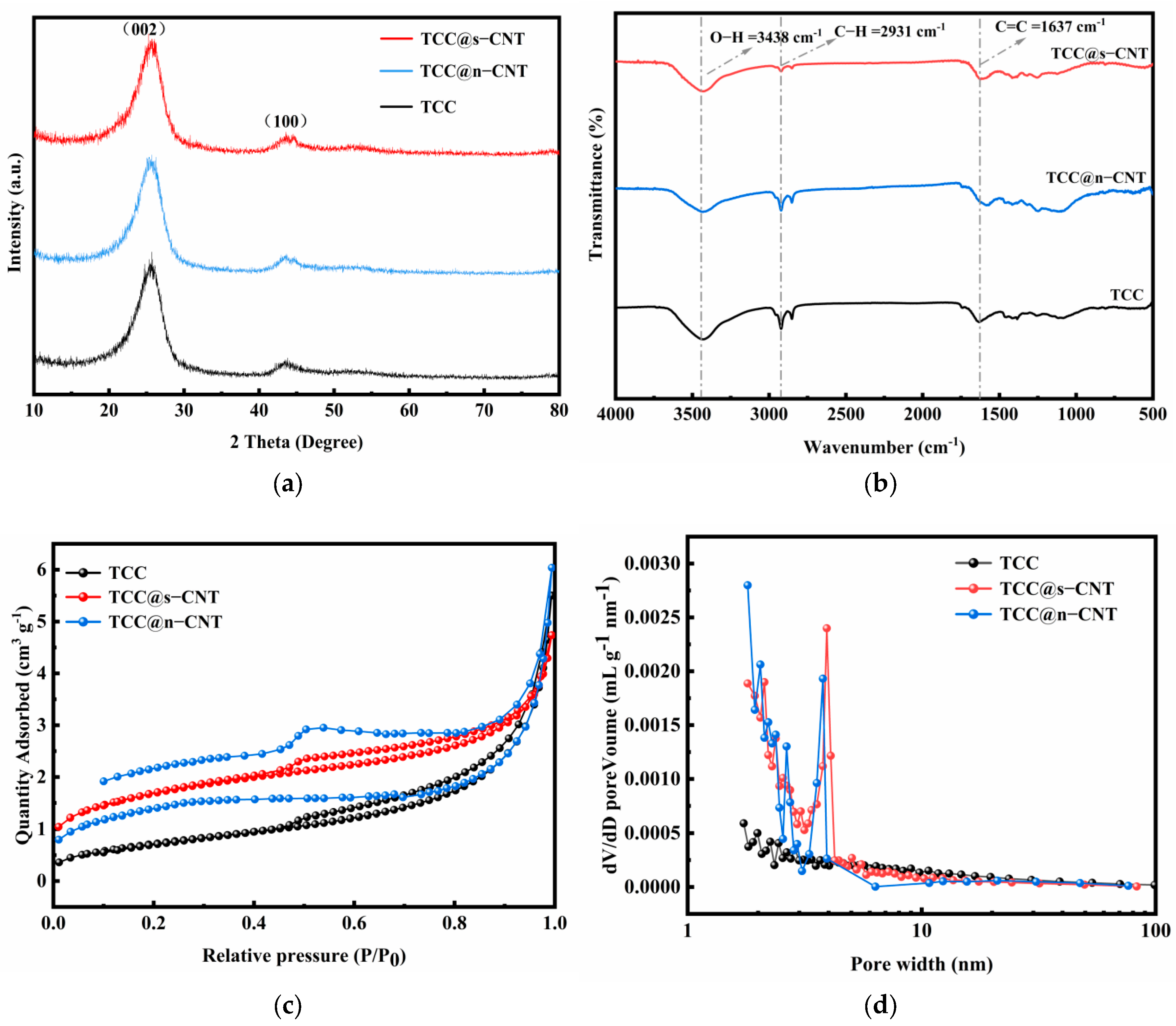
2.1. Morphology and Structure Characterizations

The SEM results of each sample are shown in Figure 1. Pores appeared on the surface of the carbon fiber after thermal oxidation treatment (see Figure 1a). This morphological change can be attributed to the preferential etching of the amorphous region during the oxidation process [37]. Surface etching not only increases the specific surface area but may also introduce oxygen-containing functional groups, providing ideal nucleation sites for subsequent CNT growth and enhancing interfacial adhesion [38]. Therefore, based on TCCs, CNTs were successfully grown on the sample surface, as shown in Figure 1b,c. The spiral-shaped TCC@s-CNTs were formed at high temperature for 1 h (Figure 1b). The formation of such a structure is related to the non-steady-state supply of carbon sources caused by the limited growth time. A short growth time may lead to the dynamic behavior of the FeCl3 catalyst particles, such as the surface tension gradient caused by the Marangoni effect, which induces periodic variations in the tube diameter. The high density of defect structures (such as pentagonal/heptacyclic rings) in helical CNTs is closely related to the step flow mechanism in the early stage of carbon cap formation. The literature points out that the helicity of CNTs is determined by the curvature of their initial carbon caps, which is affected by the angle between adjacent crystal planes on the catalyst surface [39]. Hence, TCC@s-CNTs may endow the material with special electronic transport properties or enhance mechanical flexibility. After 3 h of heat preservation, a network-structured TCC@n-CNT was formed (Figure 1c). The extended growth time allows CNTs to undergo two stages: longitudinal growth and lateral self-assembly. The van der Waals force-induced inter-tube interactions promote the construction of a three-dimensional network on the TCC@n-CNT surface.
The structures of each obtained sample were further analyzed, as shown in Figure 2. In Figure 2a, the XRD results show that after CNTs grow on the TCC surface, the half-peak width corresponding to the (002) crystal plane increases, and the peak intensity decreases slightly. This indicates that the TCC@s-CNT and TCC@n-CNT reduce the degree of graphitization of the electrode material and increase the quantity of defects. This is consistent with the theory in the Scherrer equation that lattice distortion leads to the broadening of diffraction peaks [40]. This result is also in line with the introduction of structural defects in CNTs grown in the gas phase due to rapid growth kinetics, resulting in a decrease in the orderliness of graphite microcrystals [41]. Further comparison also revealed that the half-peak width of the (002) crystal plane of the TCC@s-CNT is larger than that of the TCC@n-CNT, confirming the higher defect density of the helical CNT. The high defect density formed during the growth process of helical CNTs is related to the additional defects caused by stress release or twisted structures [42]. Similar studies have demonstrated that sp3 hybridized carbon or edge defects are more pronounced in curled or helical CNTs [43].
In Figure 2b, the FTIR results reveal that the most significant difference in functional groups on the surface of each sample is the C-H= bond stretching vibration peak appearing at 2930 cm−1. At this position, the peak intensity of the TCC is the most remarkable, while that of the TCC@n-CNT and TCC@s-CNT is weakened. The above results indicate that CNT coating reduces the exposure of functional groups on the surface of carbon fibers. This phenomenon is related to the thermal decomposition or structural reorganization of surface functional groups (such as -CH3 and -CH2) caused by high-temperature conditions during CNT growth [44]. The vibration peak of the C=C bond in the TCC@s-CNT and TCC@n-CNT appears at 1637 cm−1 and is broader than that of TCC, while the vibration absorption peak of the C-O bond connected to the aromatic structure near 1220 cm−1 is also weaker than that of TCC. The literature manifests that carbon defects can enhance the local electronic environment disturbance of the C=C bond, thereby affecting the infrared absorption characteristics [41]. The decrease in C-O peak intensity and the broadening of the C=C peak further support the conclusion that the degree of graphitization of the TCC@s-CNT and TCC@n-CNT has decreased; that is, the carbon structure of CNTs grown on the surface of carbon fibers is not as complete as that of TCC. Meanwhile, further observation also reveals that the peak intensity of the C-H= bond and C-O bond in the TCC@s-CNT is significantly weaker than that of the TCC@n-CNT. Generally, the TCC@n-CNT may partially repair defects due to the longer growth time, while the spiral-shaped TCC@s-CNT retains more defects due to rapid growth and stress accumulation. Because the defects of in situ grown CNTs can also achieve high defect density by regulating the catalyst and gas ratio, the structural changes here are likely related to the introduction of melamine [24]. The XPS results further confirm the impact of melamine on the structural characteristics of the TCC@n-CNT and TCC@s-CNT. Specifically, the contents of C, N, and O elements, as well as the proportions of the primary chemical bonds formed, are detailed in Table S1. The results demonstrate that in addition to an increased content of oxygen functional groups, nitrogen functional groups dominated by pyrrolic nitrogen were also formed within the samples.
The specific surface area of each sample is 2.68 m2/g (TCC), 5.81 m2/g (TCC@s-CNT), and 4.88 m2/g (TCC@n-CNT). It is obvious that the introduction of CNTs greatly expands the reaction surface area of the electrode. The surface characteristics of each sample are illustrated in Figure 2c,d. In addition to the TCC@s-CNT and TCC@n-CNT exhibiting greater adsorption compared to TCC, the broad loop observed for the TCC@n-CNT suggests the presence of numerous mesoporous structures, which further corroborates its three-dimensional network structure. Furthermore, as shown in Figure 2d, the TCC@s-CNT and TCC@n-CNT possess significantly more micropores than TCC, with their pore sizes predominantly concentrated around 7 nm.

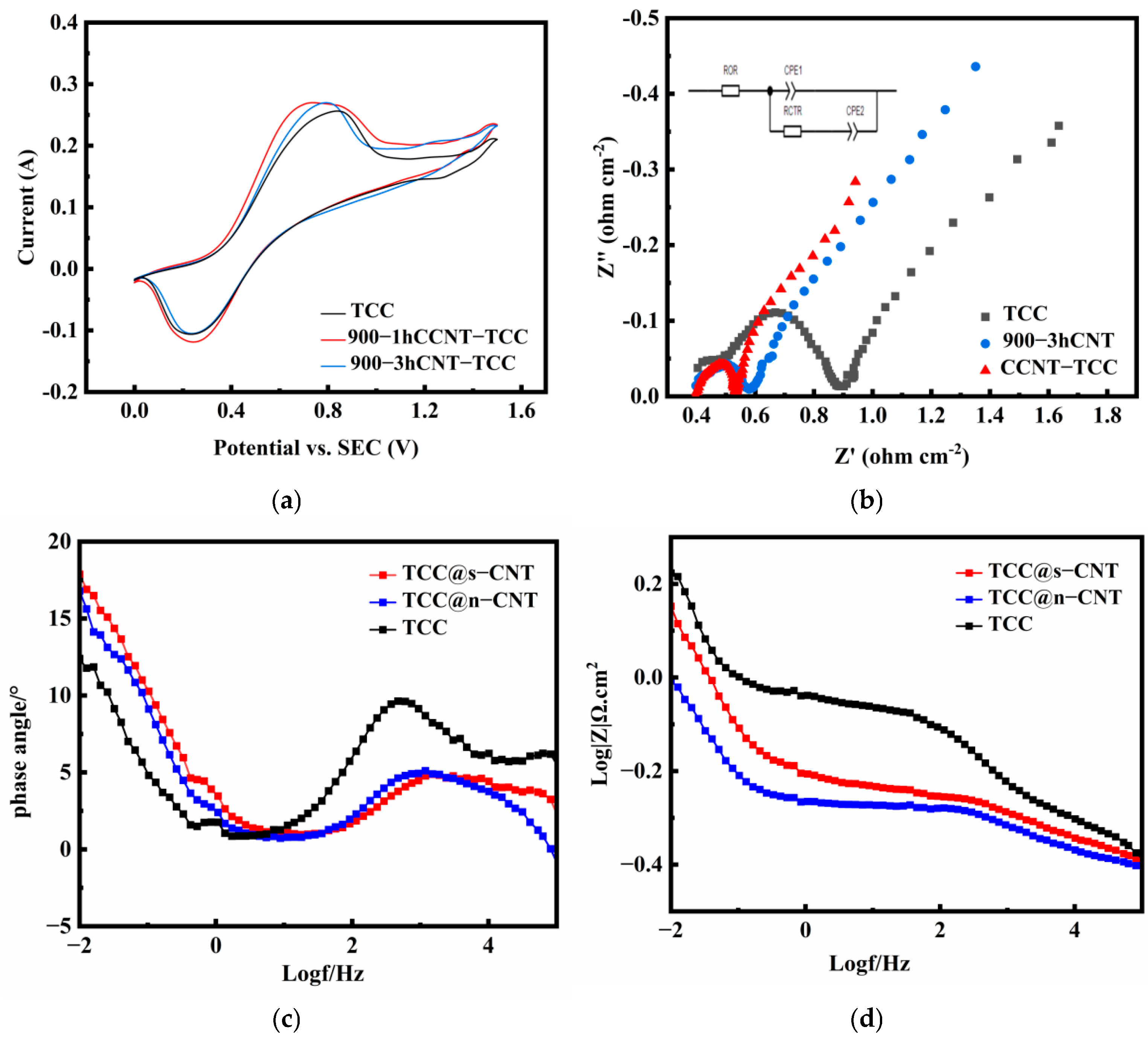
2.2. Electrochemical Properties

The electrochemical results of each sample are reported in Figure 3. In Figure 3a, the oxidation–reduction peaks corresponding to V4+↔V5+ can be observed on the surfaces of all three samples, and the parameters of each peak are listed in Table 1. Among them, △E represents the peak potential difference, and Ipa and Ipc represent the peak currents of the anode and cathode, respectively. The results demonstrate that while the TCC@s-CNT and TCC@n-CNT increase the Ipa and Ipc, the ΔE is also reduced compared with TCC, especially in the case of the TCC@s-CNT. The above results show that growing CNTs on the surface of TCC can catalyze the positive electrode reaction of VRFBs. The defective structures attributed to CNTs (such as sp3 hybridized carbon or edge sites) provide more electrochemically active sites, promoting the adsorption and reaction of V4+/V5+ [42].
The EIS of each sample was fitted according to the equivalent circuit in Figure 3b, and the obtained parameters are listed in Table 1. Rs represents the ohmic resistance of the circuit, RCTR stands for the electrochemical reaction impedance, and CPE1 and CPE2 represent the capacitive elements. In Table 1, the Rs value of TCC@s-CNTs and TCC@n-CNTs is slightly lower than that of the TCC. Despite the lower graphitization degree of these two samples compared to the TCC, the increase in functional groups and surface area enhances the hydrophilicity. This enhanced electrolyte infiltration reduces interfacial resistance, resulting in the lower Rs values of TCC@s-CNTs and TCC@n-CNTs compared to TCC. Nevertheless, the defective structure of CNTs does not significantly impact the bulk conductive network. This finding can be further validated through the internal resistance test of the battery prior to the single-cell charge–discharge cycle. In addition, the CNT significantly reduces the electrochemical impedance of the electrode reaction, and the RCTR value generated by the TCC@s-CNT is the smallest. This further confirms that the CNT reduces the electrochemical polarization by enhancing the electrode surface reaction kinetics. This phenomenon is closely related to the high specific surface area of CNTs and the increase in the density of active sites induced by defects [23,26].
The Bode plots for each sample are presented in Figure 3c,d. Figure 3c illustrates the relationship between the phase angle and frequency. As depicted, the three samples exhibit pronounced peak phase angles within the medium-frequency range, which indicates the presence of a charge-transfer process. Figure 3d demonstrates the relationship between the modulus value and frequency. The results reveal that the impedance modulus of TCC is higher than that of the TCC@s-CNT and TCC@n-CNT in both low- and high-frequency regions, suggesting that the TCC has a larger charge-transfer resistance and electrolyte ohmic resistance on its surface. These characteristics align with the RCTR and Rs values obtained through EIS fitting. Due to the influence of double-layer capacitance, the RCTR value of the TCC@n-CNT in the Bode plot is lower than that of the TCC@s-CNT.
In the comparison of electrochemical properties, it can be concluded that the catalytic performance of the TCC@s-CNT (spiral-shaped CNT) is superior to that of the TCC@n-CNT (network-structured CNT). The reasons for this result may include two aspects: (i) a difference in the defect density: the helical CNTs have a higher defect density due to growth stress or twisted structure, which further increases the active sites; (ii) surface functional group regulation: the higher density of oxygen functional groups in TCC@s-CNTs suggests a more rapid electrode reaction.

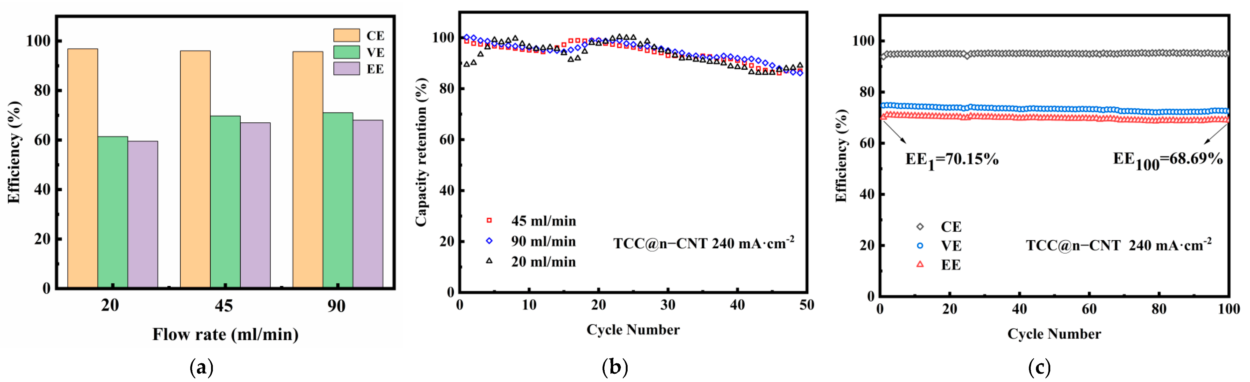
2.3. Single-Cell Cycling Test

The TCC, TCC@s-CNT and TCC@n-CNT were used as cathode electrodes; the TCC was employed as the anode electrode to assemble single cells, and the efficiencies (coulombic efficiency, CE; voltage efficiency, VE; energy efficiency, EE) and capacity retention (CR) rate of the single-cells under various current densities were obtained, as shown in Figure 4. In Figure 4a, the CE values of each single cell rises with the increase in current density, while the VE value demonstrates an opposite trend. The CE value of the VRFB assembled with the TCC@s-CNT is the largest, and the CE values of the TCC and TCC@n-CNT are relatively close. At a current density of 80 mA/cm2, the CE value of the VRFB containing the TCC@s-CNT is 93.67%, which is about 3.3% higher than that of the TCC and TCC@n-CNT. Nevertheless, as the current density increases, the CE values of the VRFB assembled with the TCC and TCC@n-CNT remain comparable, while the disparity in CE values between the TCC@s-CNT and the other two samples progressively diminishes. At a current density of 240 mA/cm2, the CE value of the VRFB containing the TCC@s-CNT is 95.93%, which is only about 1% higher than that of the TCC and TCC@n-CNT. The reason for this phenomenon should be related to the crossover or permeation of V4+/V5+ in the membrane [45,46]. In the environment of the Nafion membrane, the size of hydrophilic ion channels (3~5 nm) is much larger than the hydration diameter of vanadium ions (about 0.6 nm), and V4+/V5+ is highly prone to penetrate from the cathode to the anode, resulting in phenomena such as vanadium ion valence imbalance and water migration [47,48]. At low current densities, VRFBs assembled with the TCC@n-CNT exhibit a lower CE value than that of those with the TCC@s-CNT. The reason may be that short CNTs (TCC@s-CNTs) may increase the CE value through a shorter charge-transfer distance [35]. However, the network structure of the TCC@n-CNT cannot function at low current densities (<120 mA/cm2). Under ahigh current density (>160 mA/cm2), the improvement in fluid dynamics conditions (such as the turbulence promotion effect) may partially offset this negative impact, reducing the difference in CE values between the two. Similar strategies have been successfully applied in other systems (e.g., lithium–sulfur batteries), such as the use of CNT/C3N4 composite structures to suppress polysulfide shuttles. The mechanism is comparable to that of blocking vanadium ion penetration [49].
However, in terms of the effect on VE values, the VRFB assembled with the TCC@n-CNT consistently exhibits a large VE value at various current densities. At a current density of 240 mA/cm2, the VE value of the VRFB containing the TCC@n-CNT can reach 74.8%. It can be seen that the synergistic effect of long CNTs and carbon fibers in the TCC@n-CNT forms a three-dimensional conductive network, shortening the ion diffusion path, enhancing the electrode–electrolyte contact, and optimizing the charge-transfer path. Zhang et al. pointed out through simulation that the tangled structure of long CNTs can form hierarchical pores, shortening the ion diffusion path to one-third of that of traditional carbon cloth [36]. The electrode polarization intensifies at high current densities, and the quality of the conductive network becomes critical. On the other hand, the VRFB assembled with the TCC@s-CNT has a VE value that is basically the same as TCC at low current densities (80 mA/cm2~160 mA/cm2) and even lower than TCC at high current densities (200 mA/cm2~240 mA/cm2). Although short CNTs (s-CNTs) have higher catalytic activity due to the exposure of more edge sites, they possess fewer contact points at high loads, resulting in an uneven local current density. Their conductive network is prone to breakage under high currents, leading to charge recombination losses. This explains the phenomenon that the VE value of the VRFB containing the TCC@s-CNT decreases under high current densities. Although in Section 2.2, the catalytic activity of the TCC@s-CNT is superior to that of the TCC@n-CNT. Nevertheless, in a single cell, the role of the flow field cannot be ignored. The TCC@n-CNT may form a more efficient electronic transport network, which reduces charge recombination losses and improves the reaction kinetics of the electrode through interface optimization.
As shown in Figure 4b, under the dual influence of CE and VE, the EE value of the VRFB containing the TCC@s-CNT is the highest at 80 mA/cm2, reaching 85%. Afterwards, the advantage of the EE value for the VRFB containing the TCC@n-CNT gradually emerged. When the current density exceeds 160 mA/cm2, the EE value of the VRFB assembled with the TCC@n-CNT at each current density is higher than that of the TCC and TCC@s-CNT. At 240 mA/cm2, the EE value of the VRFB containing the TCC@n-CNT reaches 71%. Above 120 mA/cm2, the capacity of the battery containing the TCC@n-CNT is always higher than that of the TCC and TCC@s-CNT, especially under high-current-density conditions, where the capacity advantage of the VRFB with the TCC@n-CNT is more significant, as shown in Figure 4c. At 240 mA/cm2, the capacity of the battery containing the TCC@n-CNT can still reach nearly 70%, which is about 15% higher than that of the TCC@s-CNT and about 20% higher than that of the TCC. It can be seen that the three-dimensional network structure formed by the TCC@n-CNT plays an important role in the positive electrode reaction of VRFBs.
To further optimize the relationship between the network structure of the TCC@n-CNT and the flow field, Figure 5 demonstrates the performance of the battery assembled with the TCC@n-CNT at 240 mA/cm2 under different electrolyte flow rates. In Figure 5a, from the CE value perspective, the lower the flow rate, the greater the CE value obtained by the VRFB, that is, in descending order of CE 20 mL/min (CE = 96.85%) > 45 mL/min (CE = 96.03%) > 90 mL/min (CE = 95.73%). It can be seen that the network structure of the TCC@n-CNT has a hierarchical (micropore–mesopore synergistic) pore structure, which is more conducive to electrolyte penetration at low flow rates. But in terms of VE values, the higher the flow rate, the greater the VE value obtained by the VRFB, that is, in the order of VE from small to large: 20 mL/min (VE = 61.40%) < 45 mL/min (VE = 69.75%) < 90 mL/min (VE = 71.05%). Similarly, the continuous network of the TCC@n-CNT establishes a continuous penetrating electrical conduction pathway, which accelerates the load transfer at high flow rates. Hence, under the influence of the VE value, the higher the flow rate, the greater the EE value obtained by the VRFB.
Figure 5b further provides the capacity retention of the VRFB assembled with the TCC@n-CNT within 50 cycles of cyclic charging–discharging at three different flow rates. The results show that the capacity of the VRFB containing the TCC@n-CNT is the most unstable at a flow rate of 20 mL/min. Compared with the flow rate of 90 mL/min, the stability of VRFB assembled with the TCC@n-CNT at a flow rate of 45 mL/min is slightly better. Therefore, the efficiency of the VRFB under 100 cycles of cyclic charging–discharging is shown in Figure 5c. The results indicate that the EE value of the first cycle is 70.15%, the EE value of the 100th cycle is 68.69%, and the total loss of EE value for 100 cycles is 1.46%. The stability of other efficiencies is also maintained well. The structural changes of the TCC@n-CNT before and after the battery cycling process are presented in Figure S1. TEM analysis revealed that the CNTs on the electrode surface underwent a certain degree of electrolyte-induced erosion during the battery cycle. Specifically, the initial bamboo-like tubular structure was etched and became uneven (see Figure S1a,b). XPS results further corroborated the extent of etching, as illustrated in Figure S1c–e. Notably, the carbon structure exhibited the most significant damage, with a corresponding increase in the content of C-O bonds and a decrease in pyrrole nitrogen content, as detailed in Table S1. However, the XRD data indicated that the half-peak width of the (002) crystal plane of the TCC@n-CNT (100 cycles) decreased slightly, which can be attributed to the exposure of CNTs due to the etching of the carbon cloth substrate.

3. Materials and Methods

3.1. Electrode Fabrication

Firstly, CC (Jingu Carbon Material Co., Ltd., Liaoning, Liaoyang, China) was thermally treated at 500 °C in an air atmosphere for 5 h to obtain TCC. A 60 mL mixed solution (deionized water and methanol (Kermel, Tianjin, China, purity 99.5%) with a volume ratio of 1:1) was prepared, and then 0.5 mM sodium hydroxide (0.02 g NaOH dissolved in 100 mL H2O) (Kermel, Tianjin, China, purity 98%) was added and ultrasonically treated for 10 min to fully dissolve the solid in the solution. Next, 3 mM FeCl3 (0.5 g FeCl3 dissolved in 100 mL H2O) (Macklin, Shanghai, China, purity 99.0%) was added to the solution and stirred until it dissolved completely. Subsequently, the TCC was immersed in the mixed solution and ultrasonically treated for 30 min (180 W, 40 kHz), and then the carbon cloth was thoroughly dried in a drying oven.
Secondly, melamine (Macklin, Shanghai, China, purity 99.0%)/carbon cloth was placed in a tube furnace with a mass ratio of 5:1 and thermally treated to 350 °C for 20 min at a heating rate of 5 °C/min under a nitrogen atmosphere. It was then heated to 900 °C at 5 °C/min and kept at this temperature for 1 h or 3 h and then cooled naturally. The TCC@s-CNT and TCC@n-CNT were obtained, respectively. Finally, the TCC@s-CNT and TCC@n-CNT were washed in 2 M H2SO4 at 60 °C for 2 h to remove any residual Fe catalyst. The obtained sample was washed with deionized (DI) water and ethanol until neutral.

3.2. Material Characterization

The surface morphology of the obtained samples was characterized using SEM (JSM-7800 F, Oxford Instruments, Abingdon, UK), the crystal structure was analyzed using XRD (SHIMADZU-7000S, Shimadzu Corporation, Kyoto, Japan) in the range of 10° to 80°, and Fourier transform infrared spectroscopy (FT-IR, Nicolet IS50, Thermo Fisher, Waltham, MA, USA) was employed to identify the chemical composition of the materials. The specific surface area of the samples was determined using the Brunauer–Emmett–Teller (BET) method, while the pore size distribution was analyzed via the Barrett–Joyner–Halenda (BJH) method, employing an ASAP2460 gas analyzer (Micromeritics, Norcross, GA, USA). The surface elemental composition of the samples was analyzed using X-ray photoelectron spectroscopy (XPS, Thermo Fisher, Waltham, MA, USA) with an Escalab 250xi X-ray source.

3.3. Electrochemical Measurement

All electrochemical measurements were performed on an electrochemical workstation (CorrTest, CS310H, Hubei, Wuhan, China). The working electrode, counter electrode, and reference electrode were the sample electrode, platinum electrode, and saturated calomel electrode, respectively. For the VO2+/VO2+ redox reactions, 3 M H2SO4 + 1.65 M VO2+ solution was used as the electrolyte. The cyclic voltammetry (CV) curves were measured at a scan rate of 5 mV/s with a scanning voltage interval of 0 V to 1.5 V (vs. SCE). Furthermore, the electrochemical impedance spectroscopy (EIS) was tested by applying a 10 mV alternating voltage in the frequency range of 100 kHz to 100 Hz and was performed at a polarization potential of 0.9 V (vs. SCE).

3.4. Battery Test

The single-cell test was subjected to constant current charging and discharging experiments using a homemade VRFB device and a constant current charging and discharging instrument (LANHE CT3002A, Hubei, Wuhan, China). The homemade VRFB single cell adopted Nafion 212 as the ion-exchange membrane, copper plates as the current collectors, and a graphite plate as the bipolar plate. The TCC, TCC@s-CNT, and TCC@n-CNT samples were used as the working electrodes (size: 5.5 cm × 2 cm), respectively, and the electrolyte (catholyte: 3 M H2SO4 + 1.65 M VOSO4, 50 mL; anolyte: 3 M H2SO4 + 1.65 M VOSO4, 50 mL) was continuously pumped into the single-cell compartment from the external tank at different flow rates. There was no special flow path treatment on the graphite bipolar plate and the electrode, and the electrolyte flowed freely through the pores inside the electrode after passing through the bipolar plate. The cut-off voltages for charging and discharging were 1.6 V and 0.8 V, respectively.

4. Conclusions

This paper systematically explores the influence mechanism of CNTs with different morphologies grown on the surface of thermally oxidized carbon cloth on its structural characteristics and electrochemical performance. The structure–function relationship between the short helical TCC@s-CNT and the long mesh TCC@n-CNT was revealed through SEM, XRD, FT-IR, and electrochemical tests, and the performance difference and mechanism of action between the two in VRFBs were elucidated. It was found that the TCC@s-CNT enhances the intrinsic catalytic activity through high-density active sites but sacrifices structural integrity. Its short tube structure is prone to causing an uneven local current distribution under high current. The three-dimensional network of the TCC@n-CNT effectively alleviates concentration polarization by shortening the ion diffusion path and enhancing electrolyte penetration. The capacity retention rate of the VRFB containing the TCC@n-CNT is 70% at 240 mA/cm2, which is significantly better than that of the TCC@s-CNT (55%), which verifies the role of the three-dimensional network in improving the cyclic stability of VRFBs. This study provides important guidance for the design of VRFB electrodes, and the main findings in this work can be summarized as follows: (1) For low-current application scenarios, high-defect spiral CNTs are recommended to optimize catalytic efficiency. (2) In high-power systems, emphasis should be placed on constructing extensive CNT networks and achieving synergistic improvements in activity and stability via structural regulation (e.g., gradient CNT distribution). This advancement provides a robust theoretical foundation and technical pathway for the precise control of CNT topography and the design of gradient structures.

Supplementary Materials

The following supporting information can be downloaded at https://www.mdpi.com/article/10.3390/catal15040345/s1: Figure S1: TCC@-CNTs before and after 100 charge-discharge cycles: (a,b) TEM, XPS (vs. TCC) C1s spectrum (c), O1s spectrum (d), N1s spectrum (e) and (f) XRD; Table S1: Content of elements and corresponding main combining bonds.

Author Contributions

Conceptualization, H.Z.; methodology, H.Z. and S.L.; software, S.L.; validation, S.L. and X.H.; formal analysis, S.L.; investigation, S.L., X.H. and B.Z.; resources, H.Z.; data curation, S.L. and X.H.; writing—original draft preparation, S.L. and X.H.; writing—review and editing, H.Z. and C.S.; visualization, C.S.; supervision, H.Z. and C.S.; project administration, M.G. and H.Z.; funding acquisition, X.H., M.G. and C.S. All authors have read and agreed to the published version of the manuscript.

Funding

This work was financially supported by the National Natural Science Funds of China (Grant No. 52407239) and Dalian Polytechnic University in the undergraduate innovation and entrepreneurship training program (Grant No. 202410152053).

Data Availability Statement

The generated data are available from the corresponding author upon request.

Conflicts of Interest

The authors declare no conflicts of interest.

References

  1. Zhang, H.; Sun, C.; Ge, M. Progress in profitable Fe-based flow batteries for broad-scale energy storage. Wiley Interdiscip. Rev. Energy Environ. 2024, 13, e541. [Google Scholar]
  2. Zhao, Z.; Liu, X.; Zhang, M.; Zhang, L.; Zhang, C.; Li, X.; Yu, G. Development of flow battery technologies using the principles of sustainable chemistry. Chem. Soc. Rev. 2023, 52, 6031–6074. [Google Scholar] [PubMed]
  3. Chen, S.; Sun, C.; Zhang, H.; Yu, H.; Wang, W.-T. Electrochemical deposition of Bismuth on graphite felt electrodes: Influence on negative half-cell reactions in vanadium redox flow batteries. Appl. Sci. 2024, 14, 3316. [Google Scholar] [CrossRef]
  4. He, Z.; Lv, Y.; Zhang, T.; Zhu, Y.; Dai, L.; Yao, S.; Zhu, W.; Wang, L. Electrode materials for vanadium redox flow batteries: Intrinsic treatment and introducing catalyst. Chem. Eng. J. 2022, 427, 131680. [Google Scholar]
  5. Bayeh, A.W.; Kabtamu, D.M.; Chang, Y.-C.; Wondimu, T.H.; Huang, H.-C.; Wang, C.-H. Carbon and metal-based catalysts for vanadium redox flow batteries: A perspective and review of recent progress. Sustain. Energy Fuels 2021, 5, 1668–1707. [Google Scholar]
  6. Hu, H.; Han, M.; Liu, J.; Zheng, K.; Mu, Y.; Zou, Z.; Yu, F.; Li, W.; Zhao, T. Development status, challenges, and perspectives of key components and systems of all-vanadium redox flow batteries. Future Batter. 2024, 4, 100008. [Google Scholar]
  7. Kim, J.; Park, H. Recent advances in porous electrodes for vanadium redox flow batteries in grid-scale energy storage systems: A mass transfer perspective. J. Power Sources 2022, 545, 231904. [Google Scholar]
  8. Zhang, H.; Chen, N.; Sun, C.; Luo, X. Investigations on physicochemical properties and electrochemical performance of graphite felt and carbon felt for iron-chromium redox flow battery. Int. J. Energy Res. 2020, 44, 3839–3853. [Google Scholar]
  9. Park, M.; Jung, A.-J.; Kim, J.; Lee, H.; Cho, J. Synergistic effect of carbon nanofiber/nanotube composite catalyst on carbon felt electrode for high-performance all-vanadium redox flow battery. Nano Lett. 2013, 13, 4833–4839. [Google Scholar]
  10. Zhang, X.; Ye, X.; Huang, S.; Zhou, X. Promoting pore-level mass transport/reaction in flow batteries: Bi nanodot/vertically standing carbon nanosheet composites on carbon fibers. ACS Appl. Mater. Interfaces 2021, 13, 37111–37112. [Google Scholar]
  11. Niu, S.; Li, H.; Guo, H.; Liu, Y.; Cheng, Y. Accelerating the reduction kinetics of V4+ to V3+ on atomically Fe-N4 decorated carbon nanotubes for vanadium electrolyte preparation. Small 2024, 20, 2405827. [Google Scholar]
  12. AlNahyan, M.; Mustafa, I.; Alghaferi, A.; Almarzooqi, F. Porous 3D graphene/multi-walled carbon nanotubes electrodes with improved mass transport and kinetics towards VO2+/VO2+ redox couple. Electrochim. Acta 2021, 385, 138449. [Google Scholar]
  13. Halada, Š.; Láznička, V.; Němec, T.; Mazúr, P.; Charvát, J.; Slouka, Z. Methodology for fast testing of carbon-based nanostructured 3D electrodes in vanadium redox flow battery. Electrochim. Acta 2024, 498, 144681. [Google Scholar]
  14. Jelyani, M.Z.; Rashid-Nadimi, S.; Asghari, S. Treated carbon felt as electrode material in vanadium redox flow batteries: A study of the use of carbon nanotubes as electrocatalyst. J. Solid State Chem. 2017, 21, 69–79. [Google Scholar]
  15. Etienne, M.; Vivo-Vilches, J.F.; Vakulko, I.; Genois, C.; Liu, L.; Perdicakis, M.; Hempelmann, R.; Walcarius, A. Layer-by-Layer modification of graphite felt with MWCNT for vanadium redox flow battery. Electrochim. Acta 2019, 313, 131–140. [Google Scholar]
  16. Lv, Z.; Zhang, J.; Lv, Y.; Cheng, Y.; Jiang, S.P.; Xiang, Y.; Lu, S. The electrocatalytic characterization andmechanism of carbon nanotubes with differentnumbers of walls for the VO2+/VO2+ redoxcouple. Phys. Chem. Chem. Phys. 2018, 20, 7791–7797. [Google Scholar] [CrossRef]
  17. An, H.; Jeon, S.; Park, J.; Chung, Y. Eco-conscious one-step treatment for oxygen-containing group functionalization on CNTs using TAEA and its use in vanadium redox flow batteries. J. Energy Storage 2024, 103, 114208. [Google Scholar]
  18. Devi, N.; Singh, P.; Chen, Y.-S. Binder-free CNT-modified excellent electrodes for all-vanadium redox flow batteries. Nanomaterials 2024, 14, 767. [Google Scholar] [CrossRef]
  19. Yang, H.; Fan, C.; Zhu, Q. Sucrose pyrolysis assembling carbon nanotubes on graphite felt using for vanadium redox flow battery positive electrode. J. Energy Chem. 2018, 27, 451–454. [Google Scholar]
  20. Kim, M.; Park, J.; Yeo, G.; Ko, M.; Jang, H. Designing CNT-implanted graphite felt as a sustainable electron network for long-cycling of vanadium redox flow batteries. Carbon 2023, 206, 1–6. [Google Scholar] [CrossRef]
  21. Wang, L.; Zhao, Y.; Liu, H.; Wang, T.; Liu, C.; Chu, P.; Leung, P. Carbon nanofibers embedded in nanopores decorated graphite felt electrodes for enhanced vanadium redox flow batteries performance. J. Electroanal. Chem. 2024, 971, 118524. [Google Scholar]
  22. Yang, D.-S.; Lee, J.Y.; Jo, S.-W.; Yoon, S.; Kim, T.-H.; Hong, Y. Electrocatalytic activity of nitrogen-doped CNT graphite felt hybrid for all-vanadium redox flow batteries. Int. J. Hydrogen Energy 2018, 43, 1516–1522. [Google Scholar]
  23. Zhang, K.; Wang, H.; Zhang, X.; Liu, L.; Feng, B.; Wang, Y.; Liu, J. Controlled construction of a N-doped carbon nanotube network endows carbon felt with superior performances for high-rate vanadium flow batteries. ACS Sustain. Chem. Eng. 2024, 12, 7318–7328. [Google Scholar]
  24. Jang, J.; Shin, M.; Kwon, Y.; Jo, C. Carbon cloth modified by direct growth of nitrogen-doped carbon nanofibers and its utilization as electrode for zero gap flow batteries. Chem. Eng. J. 2024, 481, 148644. [Google Scholar]
  25. Wei, L.; Liu, T.; Zhang, Y.; Liu, H.; Ge, L. Taurine-functionalized carbon nanotubes as electrode catalysts for improvement in the performance of vanadium redox flow battery. Catalysts 2024, 14, 281. [Google Scholar] [CrossRef]
  26. Liu, L.; Zhang, X.; Zhang, D.; Zhang, K.; Hou, S.; Wang, S.; Zhang, Y.; Peng, H.; Liu, J.; Yan, C. Regulating the N/B ratio to construct B, N co-doped carbon nanotubes on carbon felt for high-performance vanadium redox flow batteries. Chem. Eng. J. 2023, 473, 145454. [Google Scholar]
  27. Jiang, Q.; Ren, Y.; Yang, Y.; Liu, H.; Wang, L.; Li, J.; Dai, L.; He, Z. High-activity and stability graphite felt supported by Fe, N, S co-doped carbon nanofibers derived from bimetal-organic framework for vanadium redox flow battery. Chem. Eng. J. 2023, 460, 141751. [Google Scholar]
  28. An, H.; Noh, C.; Jeon, S.; Kwon, Y.; Chung, Y. Green functionalization for chelating ligand-like and π-conjugated active sites on carbon nanotubes and its use for vanadium redox flow batteries. J. Energy Storage 2023, 68, 107796. [Google Scholar]
  29. Mazurenko, I.; Etienne, M.; Francius, G.; Vakulko, I.; Walcarius, A. Macroporous carbon nanotube-carbon composite electrodes. Carbon 2016, 109, 106–116. [Google Scholar]
  30. Sun, J.; Jiang, H.R.; Wu, M.C.; Fan, X.Z.; Chao, C.Y.H.; Zhao, T.S. Aligned hierarchical electrodes for high-performance aqueous redox flow battery. Appl. Energy 2020, 271, 115235. [Google Scholar]
  31. Xu, Z.; Jing, M.; Liu, J.; Yan, C.; Fan, X. Advanced dual-gradient carbon nanofibers/graphite felt composite electrode for the next-generation vanadium flow battery. J. Mater. Sci. Technol. 2023, 136, 32–42. [Google Scholar] [CrossRef]
  32. Wei, Z.; Qu, G.; Huang, Z.; Wang, Y.; Li, D.; Yang, X.; Zhang, S.; Chen, A.; Wang, Y.; Hong, H.; et al. Gradient distribution of zincophilic sites for stable aqueous zinc-based flow batteries with high capacity. Adv. Mater. 2024, 36, 2414388. [Google Scholar] [CrossRef] [PubMed]
  33. Ma, Q.; Fu, W.; Shi, H.; Chen, Z.; Su, H.; Xu, Q. An electrospinning carbon nanofiber composite electrode with gradient porous structure for deep eutectic solvent electrolyte-based iron-vanadium redox flow battery. J. Energy Storage 2023, 74 Pt A, 109392. [Google Scholar] [CrossRef]
  34. Li, J.; Lu, M.; Yang, W.; Zhang, R.; Su, J.; Xu, Q. Development of high-performance and ultra-stability hierarchical nested-network-pore carbon electrode for vanadium redox flow batteries. J. Energy Storage 2024, 97, 112987. [Google Scholar] [CrossRef]
  35. Song, F.; Wang, Z.; Sun, G.; Ma, T.; Wu, D.; Chen, L.; Li, H.; Wu, F. In-situ CNT-loaded organic cathodes for sulfide all-solid-state Li metal batteries. eTransportation 2023, 18, 100261. [Google Scholar] [CrossRef]
  36. Zhang, W.; Jin, K.; Ren, Z.; Li, L.; Chang, L.; Zhang, C.; Wang, R.; Li, B.; Wu, G.; Ying, H. High-performance MXene/carbon nanotube electrochemical actuators for biomimetic soft robotic applications. Adv. Funct. Mater. 2024, 34, 2408496. [Google Scholar] [CrossRef]
  37. Park, S.H.; Ha, J.; Kim, D.W.; Hwang, C.; Choi, J.-I.; Park, H.S.; Kim, Y. Mesoporous graphite felt electrode prepared via thermal oxidative etching on all-vanadium redox flow batteries. Chem. Eng. J. 2024, 500, 157328. [Google Scholar] [CrossRef]
  38. Yang, D.; Tian, D.; Xue, C.; Gao, F.; Liu, Y.; Li, H.; Bao, O.; Liang, J.; Zhao, Z.; Qiu, J. Tuned fabrication of the aligned and opened CNT membrane with exceptionally high permeability and selectivity for bioalcohol recovery. Nano Lett. 2018, 18, 6150–6156. [Google Scholar] [CrossRef]
  39. Rao, R.; Sharma, R.; Abild-Pedersen, F.; Nørskov, J.K.; Harutyunyan, A.R. Insights into carbon nanotube nucleation: Cap formation governed by catalyst interfacial step flow. Sci. Rep. 2014, 4, 6510. [Google Scholar] [CrossRef]
  40. He, K.; Chen, N.; Wang, C.; Wei, L.; Chen, J. Method for determining crystal grain size by X-ray diffraction. Cryst. Res. Technol. 2018, 53, 1700157. [Google Scholar] [CrossRef]
  41. Wang, W.; Shang, L.; Chang, G.; Yan, C.; Shi, R.; Zhao, Y.; Waterhouse, G.I.N.; Yang, D.; Zhang, T. Intrinsic carbon-defect-driven electrocatalytic reduction of carbon dioxide. Adv. Mater. 2018, 31, 1808276. [Google Scholar] [CrossRef] [PubMed]
  42. Sheng, J.; Han, Z.; Jia, G.; Zhu, S.; Xu, Y.; Zhang, X.; Yao, Y.; Li, Y. Covalently bonded graphene sheets on carbon nanotubes: Direct growth and outstanding properties. Adv. Funct. Mater. 2023, 33, 2306785. [Google Scholar] [CrossRef]
  43. Luob, H.; Lub, H.; Qiu, J. Carbon fibers surface-grown with helical carbon nanotubes and polyaniline for high-performance electrode materials and flexible supercapacitors. J. Electroanal. Chem. 2018, 828, 24–32. [Google Scholar]
  44. Wu, R.; Wang, X.; Ge, L.; Zheng, Z.; Zhu, Y.; Zhou, C.; Yuan, J.; Zhu, S.; Gu, Y.; Zhou, W.; et al. N, S co-doped carbon with embedment of FeNi alloy as bifunctional oxygen electrocatalysts for rechargeable Zinc-air batteries. Carbon 2023, 202, 141–149. [Google Scholar] [CrossRef]
  45. Sun, C.; Zlotorowicz, A.; Nawn, G.; Negro, E.; Bertasi, F.; Pagot, G.; Vezzù, K.; Pace, G.; Guarnieri, M.; Vito, D. [Nafion/(WO3)x] hybrid membranes for vanadium redox flow batteries. Solid State Ion. 2018, 319, 110–116. [Google Scholar] [CrossRef]
  46. Sun, C.; Negro, E.; Nale, A.; Nale, A.; Pagot, G.; Vezzù, K.; Zawodzinski, T.A.; Meda, L.; Gambaro, C.; Vito, D. An efficient barrier toward vanadium crossover in redox flow batteries: The bilayer [Nafion/(WO3)x] hybrid inorganic-organic membrane. Electrochim. Acta 2021, 378, 138133. [Google Scholar] [CrossRef]
  47. Zhai, L.; Zhu, Y.-L.; Wang, G.; He, H.; Wang, F.; Jiang, F.; Chai, S.; Li, X.; Guo, H.; Wu, L.; et al. Ionic-nanophase hybridization of Nafion by supramolecular patching for enhanced proton selectivity in redox flow batteries. Nano Lett. 2023, 23, 3887–3896. [Google Scholar] [CrossRef]
  48. Sun, C.; Zhang, H. Investigation of Nafion series membranes on the performance of iron-chromium redox flow battery. Int. J. Energy Res. 2019, 43, 8739–8752. [Google Scholar] [CrossRef]
  49. Cai, X.; Xie, J.; Guo, X.; Zheng, X.; Liu, Y.; Cao, F.; Dong, X.; Kong, Q.; Zhang, J. Suppressing polysulfide shuttle in lithium-sulfur batteries using CNTs/C3N4/S cathodes. Mater. Today Commun. 2023, 35, 106138. [Google Scholar] [CrossRef]
Figure 1. SEM results of the obtained samples: (a) TCC, (b) TCC@s-CNT, and (c) TCC@n-CNT.
Catalysts 15 00345 g001
Figure 2. Structural characterization of each sample: (a) XRD, (b) FT-IR, (c) N2 sorption isotherms, and (d) pore size distribution curves.
Catalysts 15 00345 g002
Figure 3. (a) CV, (b) EIS, and (c,d) Bode spectra.
Catalysts 15 00345 g003
Figure 4. (a) CE, VE, (b) EE, and (c) CR results of each single cell.
Catalysts 15 00345 g004
Figure 5. (a) Efficiency and (b) retention rate of the VRFB containing the TCC@n-CNT at different flow rates and (c) battery efficiency results during 100 cycles of cyclic VRFB charging–-discharging at a flow rate of 45 mL/min.
Catalysts 15 00345 g005
Table 1. Electrochemical parameters.
SamplesΔE (V)Ipa (A) Ipc(A)Ipa/IpcRS (Ω·cm2)RCTR (Ω·cm2)
TCC0.6190.25620.10942.3410.4090.479
TCC@s-CNT0.4710.26990.11872.2730.3900.125
TCC@n-CNT0.5540.26980.10602.5450.3900.170
Disclaimer/Publisher’s Note: The statements, opinions and data contained in all publications are solely those of the individual author(s) and contributor(s) and not of MDPI and/or the editor(s). MDPI and/or the editor(s) disclaim responsibility for any injury to people or property resulting from any ideas, methods, instructions or products referred to in the content.

