Abstract
A high-throughput (HT) screening platform developed at hte with the application focus on automotive catalysis is described. hte HT units are configured for performing steady-state testing, as well as dynamic tests with fast feed switches, such as lean/rich excursions for the evaluation of NOx storage capacity and efficiency of lean NOx traps (LNT), ammonia storage capacity for selective catalytic reduction (SCR), evaluation of oxygen storage capacity (OSC), as well as lambda sweep tests for screening of three-way catalysts (TWC). Even though catalysts are screened on a rather small scale (~100 mg powder), experience showed that dosing rather complex gas mixtures in concentrations close to that found in real exhaust for the given application is mandatory to generate relevant data. The objective of this work is to give additional insight into HT technology. In the industrial research laboratory, HT screening has matured to become a reliable approach for rapid screening of both reaction parameter spaces, as well as material properties relevant for exhaust gas catalyst development. Due to the speed of optimized screening involving 48 parallel reactors, automated handling of primary data is an imported requirement. Software for data reduction, like estimation of light-off temperature, needs to be robust and handle results for diverse sample libraries in an unattended fashion. In combination with the statistical design of experiment and multivariate data analysis, HT testing has become a valuable enhancement to automotive catalyst development.
1. Introduction
The development and successful implementation of advanced exhaust aftertreatment systems requires continuous catalyst improvement targeting better low temperature activity, sulfur tolerance and thermal durability associated with the reduction of precious metals and overall cost. Advanced test technologies are required for the improvement and optimization of commercial emission control catalysts [1], as well as for long-term R&D projects aimed at the development of future technologies. In the future, efficient material screening will play an essential role in the achievement of step change improvements in exhaust gas aftertreatment technologies. This is enabled by knowledge-based robot-controlled preparation and dynamic models coupled with information from real operation [2].
During the last decade, high-throughput (HT) methods have become an established tool for the evaluation of heterogeneous catalysts for different chemical processes [3,4,5,6,7,8,9,10,11,12,13,14,15,16]. hte’s approach to HT testing is based on a patent filed on 3 March 1998, which relates to parallel reactor systems for testing the activity of solid catalysts simultaneously exposed to gaseous feed streams [17]. Further developments of hte cover the parallel processing of liquid feed and handling of liquid feed products. For example, an improved system for controlling the reaction pressure in parallel reactor systems had been described [18].
Since 2000, hte has applied an HT technology platform in the field of automotive catalysis. Several successful R&D programs demonstrated the power of the rapid testing paradigm when exploring large formulation matrices. Results of fast and precise screening of chemical compositions have been described [19,20]. However, compared to other applications, the number of studies reporting on the use of HT screening for automotive applications is still relatively small [21,22,23,24,25].
In a previous publication, the main features of the hte screening platform for automotive applications were described [26]. Two case studies on (i) steady-state testing of hydrocarbon oxidation and (ii) testing of dynamic oxygen storage capacity (OSC) were given to exemplify the state of maturity of HT technology and its application for the development of exhaust gas catalysts. The intention of the current paper is to provide insight into the actual measurement in an HT reactor system with time resolved, quantitative online analytics, which is fundamentally different from other conventional catalyst screening methodologies. Since the analytical sensors are usually the cost-critical part in an experimental setup, the experimental sequence has been optimized in the HT units to make the most efficient use of these analyzers. This involves fully-automated operation of 48-fold parallel reactors and a sequence of measurements that minimizes equilibration time during and after changing experimental conditions. As a consequence, experimental results are less straight forward to evaluate than in conventional tests, and adequate software support for data processing is required.
In addition to the data handling aspect of HT testing, this manuscript will describe dynamic test protocols involving feed gas switches that have been successfully implemented on a 48-fold testing unit.
2. Results and Discussion
hte has acquired 15 years of experience in operating parallel reactors in the field of environmental catalyst screening. The most important lesson learned in this period is that relevant data can only be generated if oversimplified test conditions and sample preparation methodologies are avoided. This means that activity testing cannot neglect the well-known inhibiting effects of steam and sulfur in the exhaust. HT units are used for the fast primary screening of new materials and for accelerated catalyst evaluation by variation of test conditions (GHSV, T, feed composition, etc.) close to the values found in the actual application. An important use related to product development involves screening of large sample libraries for optimization of washcoat formulations, both in terms of composition and processing conditions. These libraries are typically defined by systematic variation of different parameters (e.g., carrier, PGM type, PGM loading, promoter type, promoter quantity, preparation route, calcination temperature, binder, slurry pH, slurry aging, etc.) based on the statistical design of experiment methods [27,28]. Even at the initial screening stage, such studies usually take hydrothermal and S-aging into account to avoid costly false positives.
In order to support actual catalyst development, close interaction with engine testing and scale-up is required. Experiments can be simplified to save time and/or costs, but any allowed simplification requires frequent re-evaluation during the progress of a research project. Since environmental catalysis is a rather mature field, every new development needs to be benchmarked against a rather high state of the art. As a consequence, HT technology is often used for incremental improvements on existing catalyst technologies, rather than for application-detached combinatorial screening using very simple conditions and giving more qualitative results. hte’s HT workflows can significantly increase the screening capacity of an environmental catalyst development lab, although the sample throughput is still orders of magnitude smaller than what is considered high throughput in pharmaceutical or biochemical fields. In combination with proper statistical tools like DoE, much larger parameter spaces can be screened in a more reliable way than with conventional experimentation.
3. Experimental Section
3.1. Description of the HT Test Unit
The key features of hte’s 3rd generation HT test reactor shown in Figure 1 can be summarized as follows.
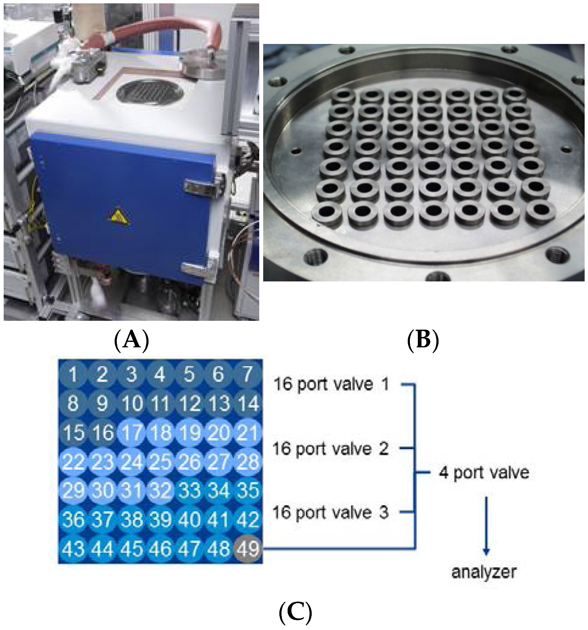
- Forty eight reaction and 1 by-pass positions with liners made from stainless steel with an inner diameter of 7 mm for each individual reactor (cf. Figure 2).
- Liner filling up to 1 mL.
- T = 110–575 °C; atmospheric pressure; GHSV (gas hourly space velocity): 30,000–100,000 h−1.
- Dosing of gases (NO, NO2, NH3, N2O, HC, CO, CO2, O2, N2) and liquids (H2O, HC).
- Online gas analyzers for NO, NO2, N2O, NH3, HC, CO, CO2, O2 and H2, as well as a mass spectrometer for specific compounds (m/z 1–512).
- Changes in feed gas composition in the s range (e.g., lean/rich cycles).
- Flexible process control (“hteControl4”) for automated experiments with complex test protocols, as well as unattended and safe 24/7 operation.
- Easy change between preconfigured operation modes (diesel oxidation catalyst (DOC), TWC, selective catalytic reduction (SCR), lean NOx traps (LNT)).
- Automated data processing and data management system (“myhte”) allowing easy data export to sophisticated data analysis solutions.

Figure 1.
Environmental catalysis high-throughput (HT) testing unit.
Figure 1.
Environmental catalysis high-throughput (HT) testing unit.
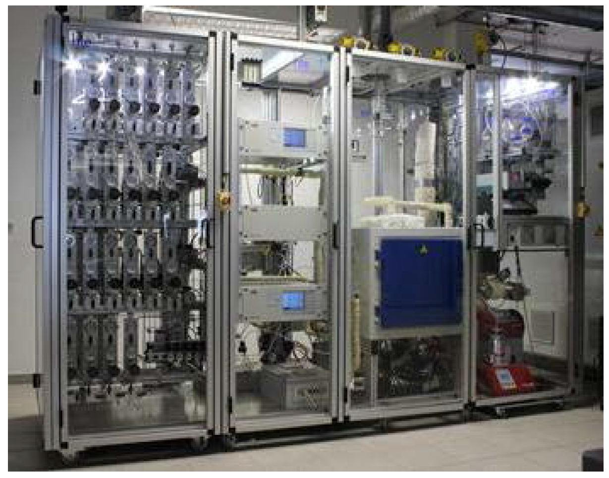
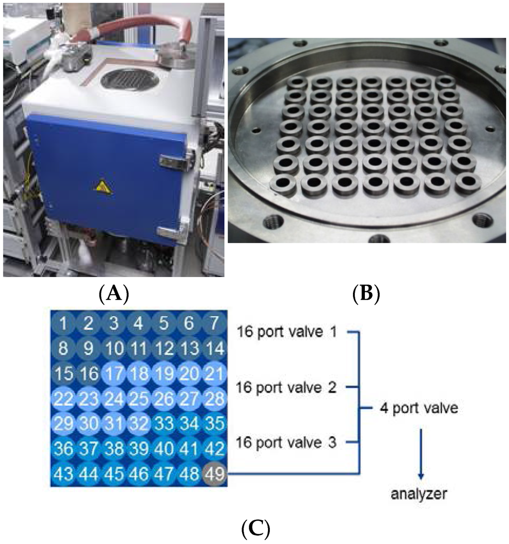
Figure 2.
Reactor layout for HT testing unit (A). The reactor (B) (closeup view) has 48 equivalent positions for catalyst screening and one position (labelled as 49), which is used as a by-pass line to perform periodic measurements of the inlet concentrations. Numbering and relation of positions are shown in part (C).
3.2. S-Aging
In addition to the actual testing units, the lab is equipped with a sulfur-aging unit having an identical 48-fold reactor block. For modelling the catalyst lifecycle, this is a valuable supplemental tool to perform catalyst evaluation regarding poisoning/regeneration behavior without liner refilling. Thus, it is possible to run sulfur aging studies during primary material screening and, therefore, reduce the number of false positive findings that would occur if more expensive experiments were conducted at a larger scale.
For evaluation of sulfur tolerance (or sulfur resistance) from exposure to sulfur oxides (SOx), different accelerated S-aging protocols are used. The main characteristics of the S-aging protocols applied at hte can be summarized as follows:
- Temperatures: 300–450 °C.
- Feed gas: 10–100 ppm SO2, 10% H2O in air; optional: 100–200 ppm NO.
- Duration: 5–70 h.
- After exposure to SO2, H2O and NO (if used), the catalysts are cooled in air.
The S-aging conditions are adjusted to the target S loading relevant for the application, and in most cases, this corresponds to 0.5–5 g·S/L for monolith catalysts with 120-g/L washcoat loading. Thermal regeneration is performed at temperatures between 600 and 800 °C using feed gas with 10% H2O in air.
3.3. Test Procedure
Screening protocols are continuously validated and optimization by integrating feedback from scale-up experiments on cores and full-sized parts in associated laboratories.
3.3.1. Catalyst Amount and Shape
The catalysts used for HT testing are shaped to a particle size of 250–500 µm. Usually, this is achieved by formulating the active components into a slurry, milling to a D50 < 15 µm, drying under agitation and crushing/sieving after calcination. A particle size fraction of 250–500 µm is typically used as a compromise between pressure drop over the catalyst bed and having a realistic inter-particle diffusion length comparable to that found in a typical washcoat thickness on a coated automotive catalyst monolith. The majority of the catalysts are tested as powders with 100–300 mg diluted to a 1-mL bed volume with corundum of the same particle size fraction. Another option often used for testing of crushed monolith catalysts uses a sieve fraction between 500 and 1000 µm. For proper comparison, catalyst amounts in each reactor are adjusted for the identical content of active components (e.g., PGM (precious group metal)). The quantity of catalyst is selected to represent that found in 1 mL of monolith catalyst, such that space velocities can be calculated with reference to 1 mL of catalyst volume facilitating the transfer and comparison of results with monolith core and full size tests.
3.3.2. Hydrothermal Aging
The catalysts are tested both fresh and after hydrothermal oven aging performed in feeds containing 5%–15% water. For diesel applications, catalysts are kept for 5–24 h at a temperature between 700 and 850 °C in water/air mixture, cooled to 300 °C in the presence of water and further to room temperature in air. Hydrothermal aging for TWC applications is performed at temperatures between 850 and 1150 °C with a duration of 5–24 h. “Rich/lean” aging is also performed with two gas feeds containing 10% water (4% H2 in N2 and air) that are switched every 10 min during aging. For quality assurance, furnaces are equipped with time-resolved monitoring of temperature and steam dosing.
3.3.3. Screening Protocols
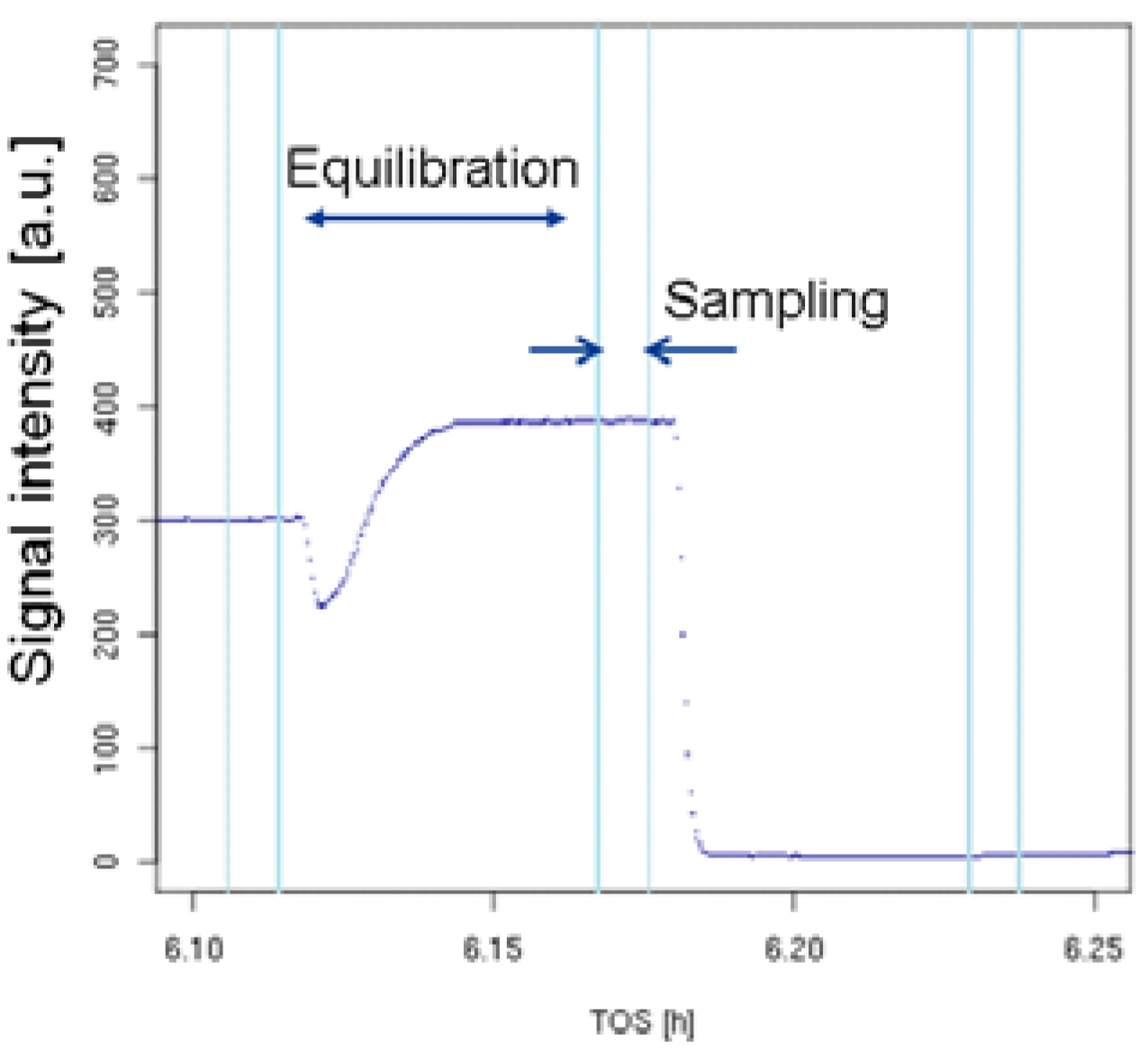
The screening protocols related to both diesel and gasoline programs can be divided into two groups in terms of HT test rig operation and data processing: (i) steady-state tests; and (ii) dynamic tests with feed switches. Testing protocols and on-line analytics are defined to be as close as possible to the conventional lab testing of automotive catalysts. Simulated exhaust feeds and test conditions are used to mimic selected operating points within regulated driving cycles (e.g., different for light-duty and heavy-duty applications). Due to the 48-fold reactor block of a high thermal mass, only isothermal operation with discrete set points is possible. Thus, no experiments with dynamic temperature ramps can be performed. During testing, all positions are exposed to the same feed all of the time, whereby the measured channel is selected by active flow control of down-stream VICI valves (cf. Figure 2). While the catalyst in a selected position is being evaluated, the remaining channels are exposed to a lower flow rate. This methodology has the advantage that all catalysts remain equilibrated close to their steady state for any given operating condition, thus allowing for short equilibration time after a new position is selected, and space velocity is increased to the target value (cf. Figure 3 for a typical response of the catalysts to the change in feed conditions). In general an experiment in the parallel reactor has the following test sequence, which is automated in the control software:
- Set first experimental condition (temperature, feed gas levels).
- Wait until the whole reactor is equilibrated.
- Switch to Position 1.
- Equilibrate in stationary feed or run dynamic feed switching program.
- Repeat Steps 3 and 4 for all 48 reactor positions.
- Set next experimental condition (e.g., higher temperature).
- Continue with Steps 2–6 until all conditions are evaluated for all 48 reactors.

Figure 3.
Time dependency of the analytical signal for selected positions in steady-state tests.
Figure 3.
Time dependency of the analytical signal for selected positions in steady-state tests.
3.3.4. Data Processing
Throughout each experiment, the process values from all sensors (temperature, flow, pressure, gas analyzers) are recorded with a frequency of 1 Hz and automatically linked by the control software to the corresponding set points for that condition, most importantly to the reactor position that is being tested. An example of the typical raw data output is shown in Figure 4 for a three-way catalyst screening protocol involving a stationary temperature ramp followed by a λ-sweep experiment. Obviously, for direct catalyst comparison, data reduction is required. This data reduction process is automated in the control software, which averages the concentration readings for each position over a predefined time interval (usually 30 s). An example of this sampling time interval after an equilibration period and before selecting the next reactor position is shown in Figure 3. Selecting this sampling interval, as well as a proper equilibration time after switching reactor positions is an important part of test protocol validation and depends on the application. In this example, for each reactor position, a 3-min equilibration time with 30-sec sampling time was defined. The average values (Figure 5) are then transferred into a relational database system (“myhte” data warehouse) and can be retrieved for further processing (e.g., using R, a language and environment for statistical computing [29]). Obviously, more complex test protocols involving the response of a catalyst to transient conditions (e.g., monitoring NOx breakthrough curves after rich spikes in LNT (lean NOx trap) testing) involve more complex data reduction steps.
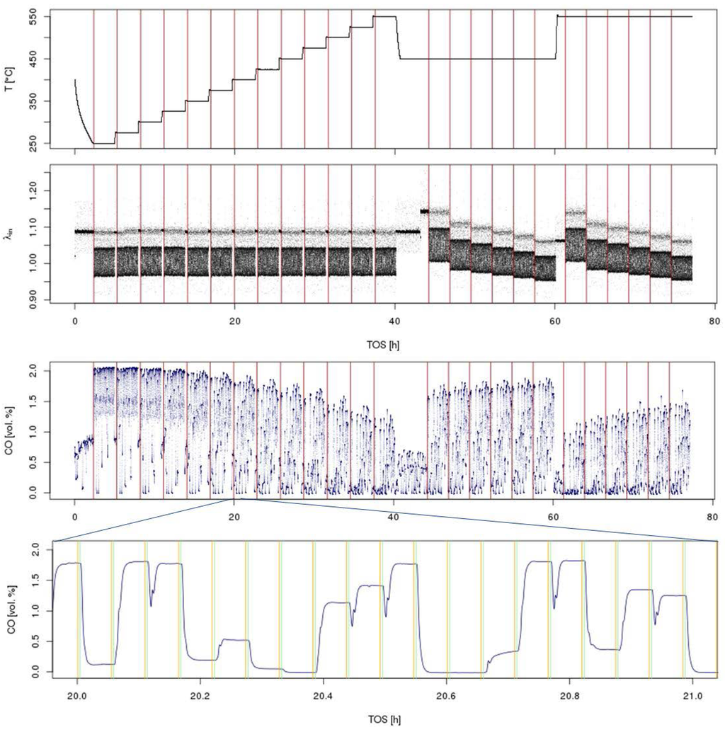
Figure 4.
Overview of time-resolved sensor readings from a typical three-way catalyst screening in a simulated gasoline engine exhaust with λ perturbation. The test involves a light-off at λ = 1 at T = 250–550 °C in 25 °C steps followed by a λ sweep at T = 450, 550 °C at 6 different λ values, 1.05, 1.02, 1.01, 1.0, 0.99, 0.98, in the sequence from lean to rich (top: temperature and λ traces; bottom: CO concentration for the whole experiment + zoom into a shorter time interval). Vertical lines in the top three graphs indicate a change in experimental conditions (T or λ); in the bottom graph, they indicate the averaging interval for each reactor position. Throughout the whole experiment, >270,000 data points are collected for each individual sensor.
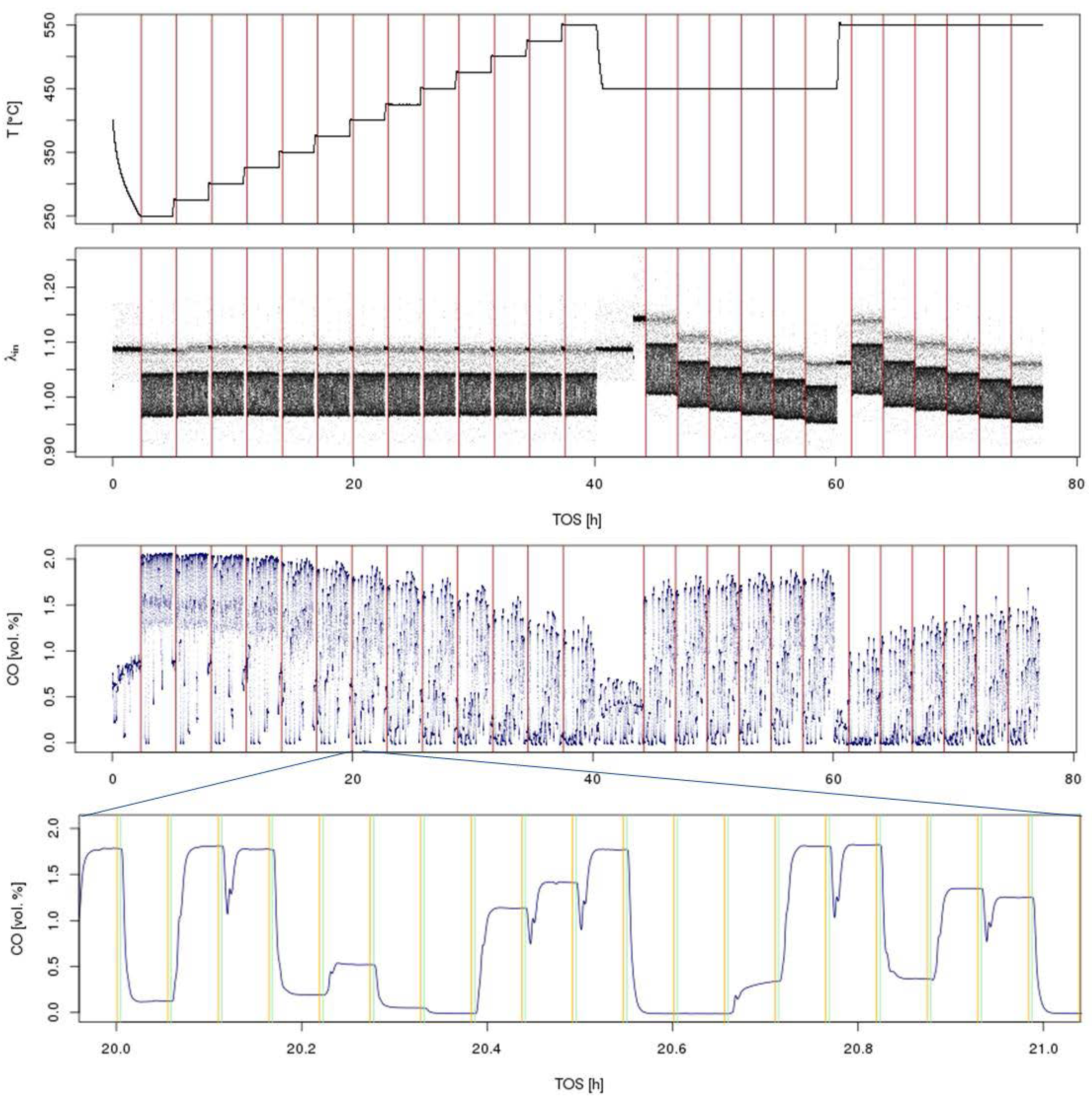

Figure 5.
Average CO concentration for each individual reactor position after the initial data reduction step. The individual subplots correspond to the different experimental conditions shown in Figure 4.
Figure 5.
Average CO concentration for each individual reactor position after the initial data reduction step. The individual subplots correspond to the different experimental conditions shown in Figure 4.

Once the results are stored in the database, it is possible to relate individual measurements, such as using the inlet concentration measured for the by-pass line, to calculate conversion. Another important step in many test protocols is the calculation of light-off temperature. From the measurement of individual gas concentrations and the calculation of conversions resulting from the stationary operation, accurate light-off temperatures are obtained from interpolation of test data obtained at the discrete temperature intervals. This interpolation methodology needs to be flexible, robust and must be applicable to all catalysts tested in the same experiment. An automated estimation of light-off temperatures was implemented for hydrocarbon conversions (X-HC) in diesel oxidation catalysts [30]. The algorithm uses logistic functions (f(T) = a/(1 + exp(−b(c − T))) as a basis and a nonlinear least squares fitting procedure to create the light-off curves shown in Figure 6. In this case, T70 (HC) at X-HC = 70% was calculated in a numerical root-finding procedure. The overall process of calculating light-off temperatures has been implemented into hte’s automated data processing workflow, so that the data reduction from a light-off experiment on 48 different samples (see Figure 7) only takes minutes and requires little human interaction. Usually, the catalysts tested together in one experiment (in the same plate or several plates tested in a campaign) are not totally unrelated, but rather, are part of a designed experiment. Utilizing the principles of the statistical design of experiments (DoE) [27,28], it is possible to quickly optimize material composition, slurry formulations, thermal activation steps or other treatments of interest. Depending on the problem, factor screening in an early stage or optimization based on previous knowledge, either fractional factorial or response surface design methodologies can be applied. As the capacity of the 48-fold parallel reactor naturally limits the number of samples, split plot designs are utilized when larger libraries of samples have to be spread over several experiments. Sometimes, computer-generated optimal designs, such as D-optimal designs, are required to ensure that these design constraints do not introduce uncontrolled statistical bias.
It must be understood that each high-throughput experiment with its complex test protocols is just a small part of a larger knowledge-finding process. To make this process robust and reliable, the following requirements for using HT testing must be taken into account: (i) continuous back-to-back comparison of stationary HTE and dynamic data to verify that the observed effects are real for the application; (ii) the HT lab must be flexible for re-optimization of test protocols (sometimes requiring modification of the unit); and (iii) there must be close integration of powder testing results with scale-up experiments in research projects.
3.3.5. Quality Assurance
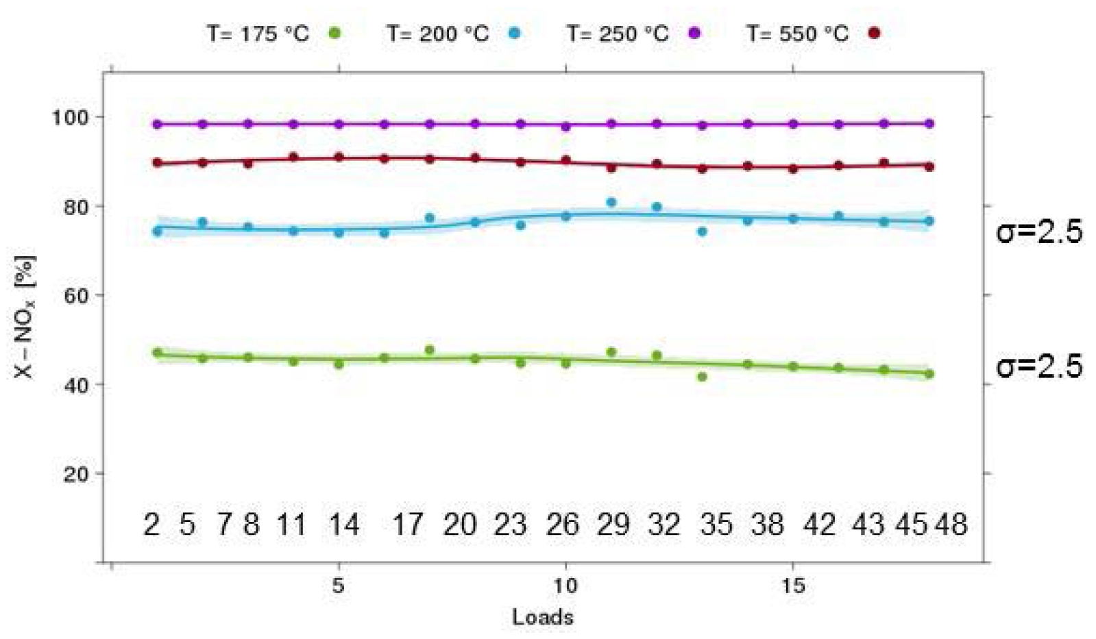
HT testing in a parallel reactor heavily relies on the assumption that all 48 channels are equivalent with respect to temperature and flow distribution. Obviously, this assumption has to be verified for any new test protocol. In Figure 8, the results for such an experiment are shown using the SCR reaction over a Cu-chabazite-based catalyst. In this case, 18 samples from the same catalyst batch were mounted on one plate. The positions were selected to cover the whole range of the reactor block. An experiment at 4 temperature levels was performed, and a satisfactory 2.5% absolute standard deviation in the measured NOx conversion was found in the light-off region, which is most sensitive to small changes in reaction conditions. Furthermore, there is no systematic trend with respect to position on the 48-fold reactor plate that would indicate problems with dosing stability or temperature distribution over the reactor block.
It is advisable to include a standard sample into every experimental plate as a check that sensor aging or contamination of lines is not causing problems. Such validation should be performed in a periodic fashion, preferably with the same standard sample to protect against creeping loss of precision. An additional measure to ensure robust data output from a parallel reactor is to ensure that factors of the experimental design are not biased with respect to either reactor position or time on stream.

Figure 6.
Light-off curves for different hydrocarbons obtained by fitting measured data points. Catalyst: 1% Pd/Al2O3 prepared from Pd nitrate as the precursor.
Figure 6.
Light-off curves for different hydrocarbons obtained by fitting measured data points. Catalyst: 1% Pd/Al2O3 prepared from Pd nitrate as the precursor.
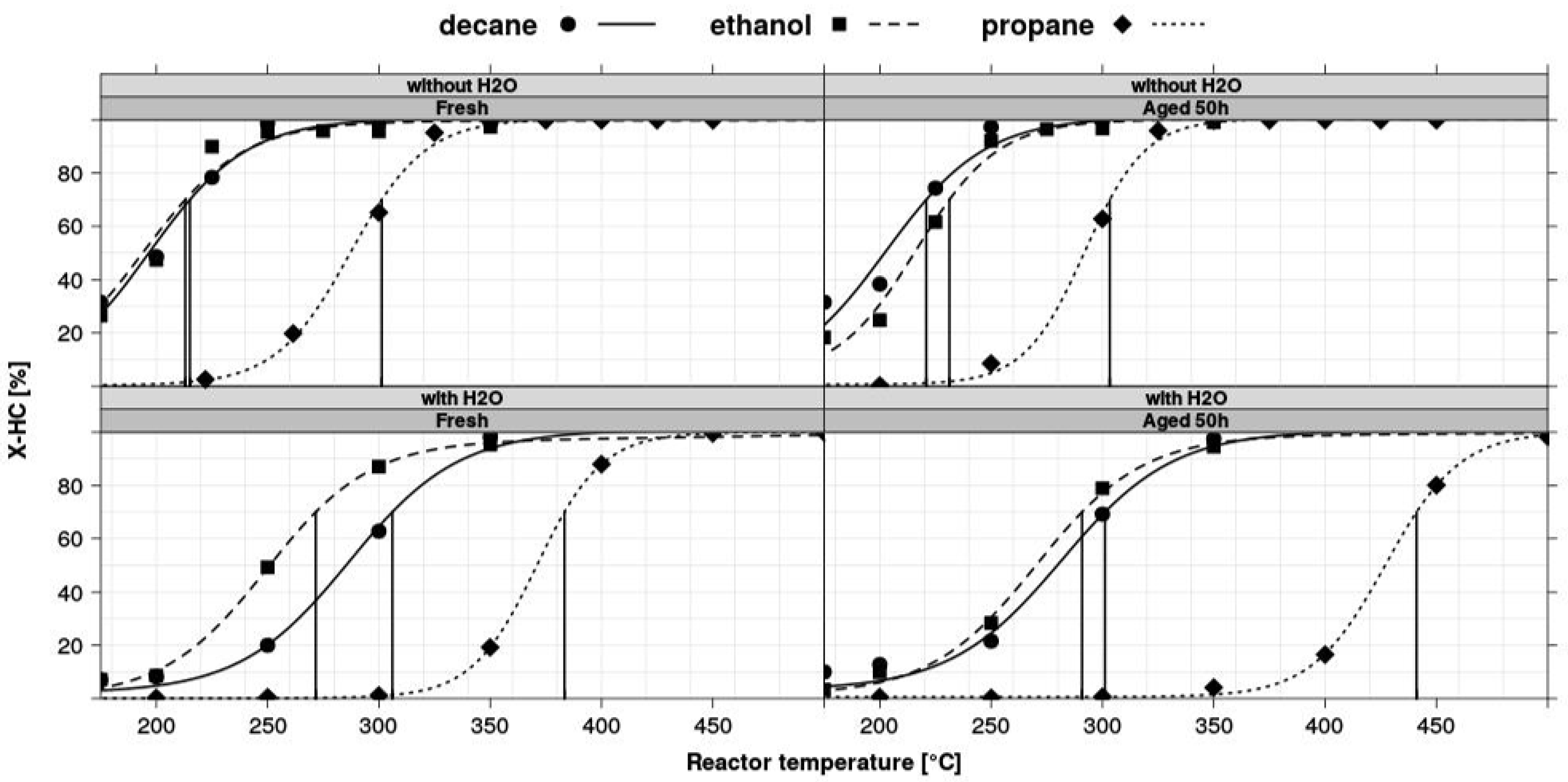
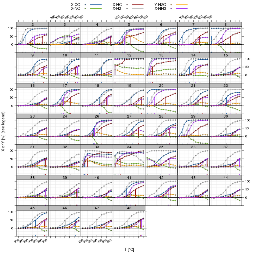
Figure 7.
Light-off curves for all pollutants in a three-way catalyst (TWC) experiment with λ perturbation; overview for all catalyst positions in a screening plate (commercial benchmarks have been omitted). The vertical lines indicate the position of T50 from the automated fitting procedure.
Figure 7.
Light-off curves for all pollutants in a three-way catalyst (TWC) experiment with λ perturbation; overview for all catalyst positions in a screening plate (commercial benchmarks have been omitted). The vertical lines indicate the position of T50 from the automated fitting procedure.
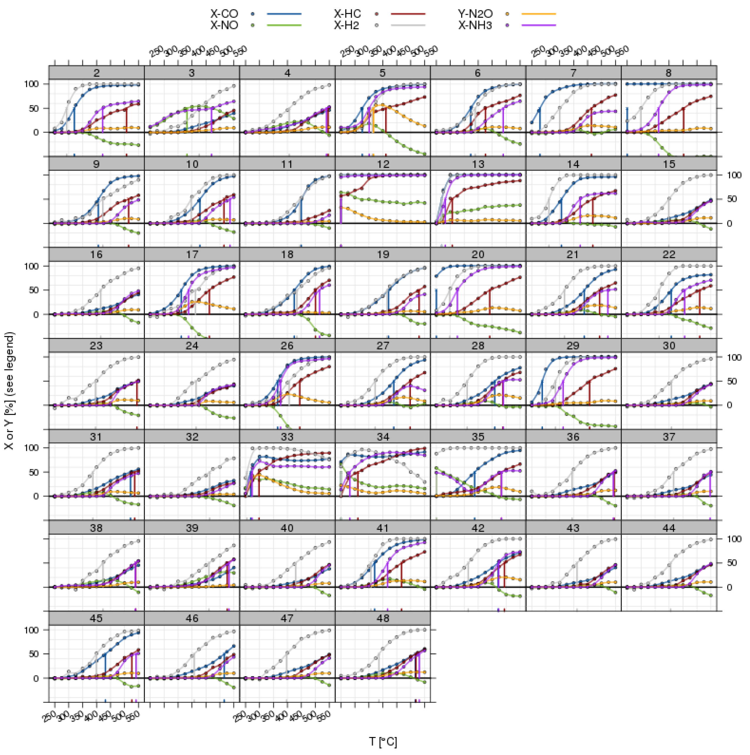
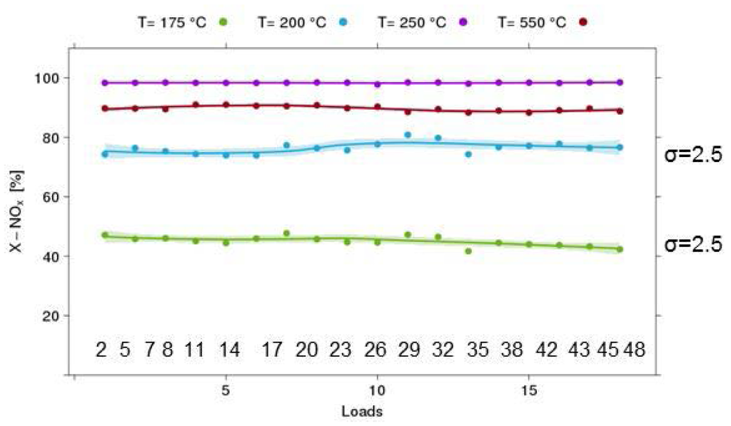
Figure 8.
Results of validation experiments on the equivalence of channels (example: 18 loads of the selective catalytic reduction (SCR) Cu-Chabazite catalyst, 120 mg/reactor, 500 ppm NO, 500 ppm NH3, GHSV 70 kh−1).
Figure 8.
Results of validation experiments on the equivalence of channels (example: 18 loads of the selective catalytic reduction (SCR) Cu-Chabazite catalyst, 120 mg/reactor, 500 ppm NO, 500 ppm NH3, GHSV 70 kh−1).
3.4. Test Protocols
At the, a variety of test protocols are applied on a routine basis. These can be split into steady-state tests and tests with dynamic feed switches. Table 1 summarizes the test conditions for some of the steady-state test protocols used at hte related to catalyst technologies for diesel emission control.
3.4.1. Steady-State Tests
- Diesel oxidation catalysts (DOC): Although new diesel cars consist of rather complex system arrangements, including a particulate filter and components for the reduction of NOx emission, the catalytic functionality to oxidize CO and HC remains an important component of diesel aftertreatment systems. Typical tests involve several stationary light-off experiments on fresh and oven-aged samples, including tests for performance after S-aging and thermal regeneration.
- Selective catalytic reduction (SCR): Experiments are performed with a simulated exhaust using NH3 as the reductant. Samples are tested under standard SCR conditions (i.e., without NO2 in the feed) and with varying levels of the NO2/NOx ratio. This test also involves a dynamic component to measure the NH3 storage capacity in a cycling feed with and without NH3.
- NH3 oxidation: An important component of an SCR aftertreatment system, the NH3 oxidation catalyst ensures removal of unconverted NH3 downstream of the SCR catalyst.

Table 1.
Overview of steady-state test protocols.
| Catalyst technology | Feed compositions | GHSV (kh−1) | Temperatures |
|---|---|---|---|
| Diesel oxidation catalyst (DOC) | 500–3000 ppm CO, 80–500 ppm-C1 HC (HC = methane, propene, octane, decane, toluene or mixtures thereof) 50–200 ppm NO 5%–10% O2, 5%–10% CO2, 5%–10% H2O | 45–80 | up to 12 temperature levels between 120 and 350 °C |
| Selective catalytic reduction (SRC) | 50–1000 ppm NO 50–300 ppm NO2 50–1000 ppm NH3 5%–10% O2, 5%–10% H2O Optional: 5%–10% CO2 50–500 ppm-C1 HC (see DOC) | 30–90 | 5–10 temperature levels between 150 and 575 °C |
| Ammonia oxidation | 50–1000 ppm NH3 5%–10% O2, 5%–10% H2O | 30–90 | 2 temperature levels between 200 and 575 °C |
3.4.2. Dynamic tests with feed switches (see Figure 9)
Three protocols are used for the evaluation of TWC (three-way catalyst) functionalities for exhaust aftertreatment in gasoline cars. Two protocols (LNT and NH3 storage) are related to the evaluation of catalyst technologies used for NOx reduction in diesel exhaust. Table 2 summarizes the corresponding test conditions.

Table 2.
Overview of dynamic test protocols with fast feed switches.
| Catalyst technology | Feed compositions | GHSV (kh−1) | Temperatures |
|---|---|---|---|
| Three-way catalysis | 1%–3% CO, 1000–4000 ppm-C1 HC (HC = methane, propene, propane, iso-butane, iso-octane, toluene or mixtures thereof) 1%–3% H2 500–2000 ppm NO 0.5%–3 % O2, 10%–15 % CO2, 10%–15 % H2O Oscillating lean/rich perturbations with defined average λ and amplitude (frequency 0.5–0.2 Hz) | 45–80 | up to 12 temperature levels between 200 and 550 °C |
| LNT (lean NOx trap) | 50–1000 ppm NO 50–300 ppm NO2 500–3000 ppm CO, 5%–10% O2, 5%–10% H2O Optional: 5%–10% CO2 50–500 ppm-C1 HC (see DOC) Rich spikes (3–10 s) with defined λ (by reducing O2 and increasing CO/H2) | 30–90 | 5–10 temperature levels between 150 and 575 °C |
| OSC (oxygen storage capacity) | Alternating gas atmosphere with 2% CO 1% O2 (variable duration 10/10 s, 30/30 s) | 60 | 2 temperature levels between 350 and 575 °C |
- TWC (three-way catalysis): Three-way catalysts operate best in an exhaust of an engine operated close to stoichiometry, an air:fuel ratio of 1. As the catalyst has to tolerate excursions from this optimal point, tests with λ perturbations are crucial. Several protocols are used to evaluate the different functionalities of fresh and aged catalysts.
- Light-off with average λ = 1 and high frequency (up to 0.5 Hz) λ perturbations.
- λ-sweep test at different temperatures. Performed by running light-off tests, but with different average lambda set points, and then plotting conversion as a function of lambda at constant temperature.
- OSC test (oxygen storage capacity): specific test for the oxygen-buffer functionality of the catalyst. Involves a feed cycling between CO and O2 in nitrogen and monitoring CO2 generation from stored oxygen. Results of this test have been previously reported [26].
 Figure 9. Examples for dynamic test protocols implemented on a 48-fold reactor system. Top left: OSC test, cycling O2 and CO containing feed and monitoring CO2 release in the absence of O2 in the gas phase, which is a measure for the oxygen storage capacity at a given temperature. Top right: NH3 storage test by cycling NH3 and monitoring the NH3 breakthrough under SCR reaction conditions (i.e., in the presence of NO, O2, H2O, optionally CO2 and/or HC). Bottom right: lean NOx traps (LNT) test with repeated rich regeneration cycles with defined λ. The NOx breakthrough is monitored and analyzed. Bottom left: TWC testing in a feed with rapid λ oscillations with defined amplitude. After an equilibration time of 150–180 s, the traces from relevant gas analyzers are averaged for 30 s.Figure 9. Examples for dynamic test protocols implemented on a 48-fold reactor system. Top left: OSC test, cycling O2 and CO containing feed and monitoring CO2 release in the absence of O2 in the gas phase, which is a measure for the oxygen storage capacity at a given temperature. Top right: NH3 storage test by cycling NH3 and monitoring the NH3 breakthrough under SCR reaction conditions (i.e., in the presence of NO, O2, H2O, optionally CO2 and/or HC). Bottom right: lean NOx traps (LNT) test with repeated rich regeneration cycles with defined λ. The NOx breakthrough is monitored and analyzed. Bottom left: TWC testing in a feed with rapid λ oscillations with defined amplitude. After an equilibration time of 150–180 s, the traces from relevant gas analyzers are averaged for 30 s.
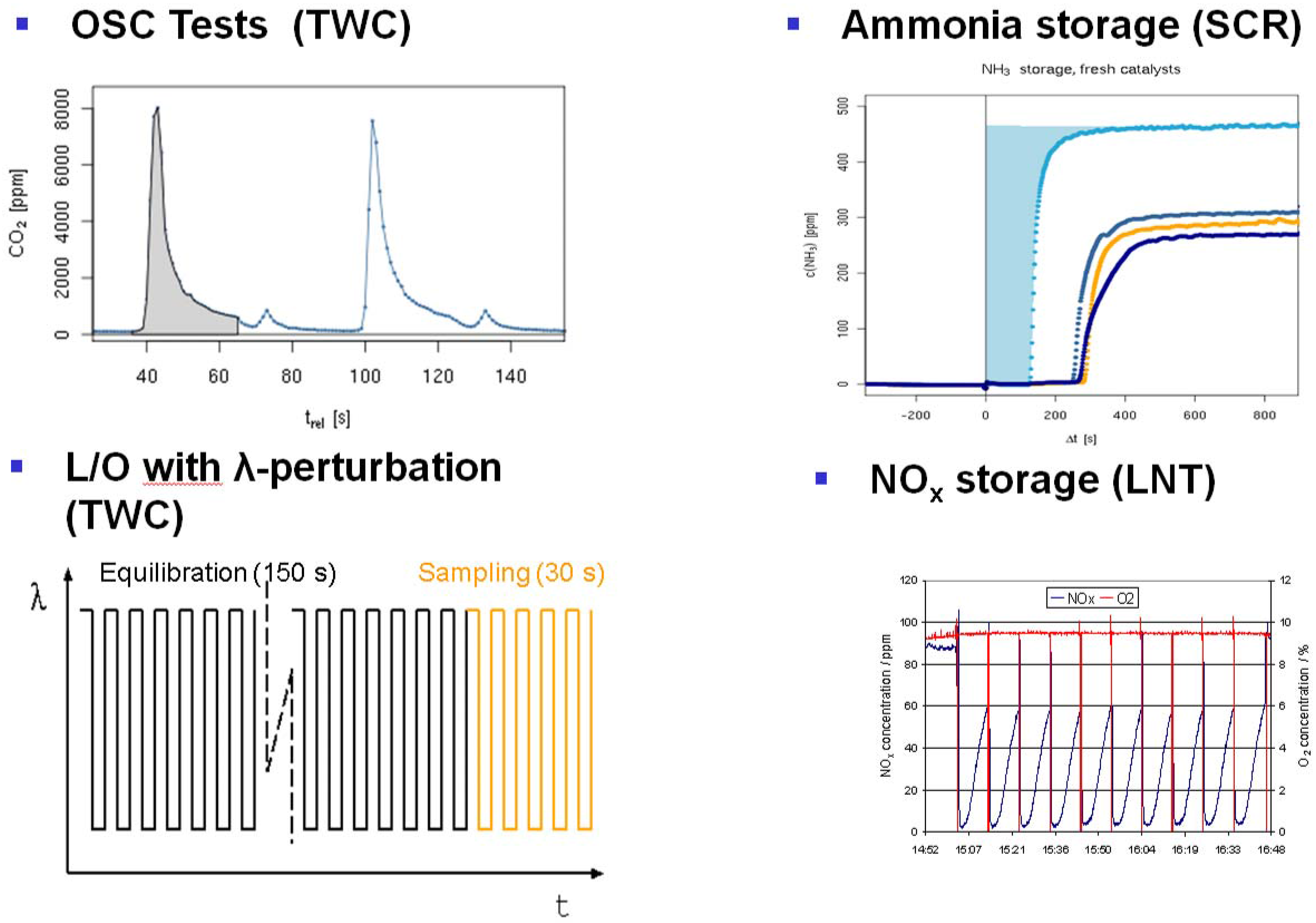
- LNT (lean NOx trap): Important for lab testing of NOx storage catalysts is the ability to generate reproducible rich pulses with defined rich λ and pulse width. Usually, 3–7 pulses are applied to each catalyst. After each rich pulse, the NOx breakthrough curve is recorded and integrated in several ways to calculate average NOx conversion or average NOx storage. Here, it is also important to compare storage in each individual rich/lean cycle and to monitor time on stream effects. The LNT test is usually run at several temperatures. A crucial component of LNT evaluation is activity after S-aging and lean/rich regeneration.
- Ammonia storage for SCR to measure the NH3 storage capacity in a cycling feed with and w/o NH3.
The typical throughput in terms of samples and the quantity of generated data points is summarize for each class of protocols in Table 3.

Table 3.
Average throughput for different test protocols.
| Topic | Performance characteristics/Protocols | Typical throughput (samples/week) | Data output (data points/week) |
|---|---|---|---|
| DOC | Light-off performance (CO/HC/NO) and sulfur resistance 2–5 light-offruns per sample | 45–135 | 4500–11,250 |
| SCR | Low and high temperature SCR performance 4 protocols (standard. and fast SCR, ammonia oxidation and storage) | 30–45 (all protocols) 45–135 (w/o NH3 storage) | 2800–4200 |
| TWC | Oxygen storage capacity (OSC) Catalytic performance: light-off, λ-sweep for CO/HC/NO | 225 (OSC) 45–90 (L/O and λ-sweep) | 900 (OSC) 6000–12,000- (L/O and λ-sweep) |
| LNT | NOx efficiencies (lean/rich and lean) and NOx storage (lean) at 3 temperatures, 5 cycles per position, two sample loads | 45 | 1800–2700 |
4. Summary
hte GmbH applies three state-of-the-art test units with 48 parallel reactors for several R&D programs in the field of environmental catalysis. High-throughput experiments have proven to be a powerful tool for rapid testing of a large number of formulations and enable fast and precise exploration of both chemical and experimental parameter spaces. To make best use of HT screening capacity-designed experiments, data processing and statistical methods for catalyst optimization are of high importance. Software and algorithms for data handling have been established and proven to be a powerful tool for handling large datasets. High throughput material testing for several automotive applications has been successfully cross-validated with the results on cores and full-sized monoliths
The results from different R&D projects demonstrate that HT screening yields high data, which can drive a rational approach to catalyst development and optimization beyond the level of pure primary material screening.
Acknowledgments
Financial support by BASF is greatly acknowledged.
Author Contributions
Olga Gerlach and Andreas Sundermann wrote the paper. Both authors conceived and designed the experiments, collected and analyzed the data and wrote the paper. Andreas Sundermann did all work related to the numerical data processing.
Conflicts of Interest
The authors declare no conflict of interest.
References
- Heck, R.M.; Farrauto, R.J.; Gulati, S.T. Catalytic Air Pollution Control, Commercial Technology, 3rd ed.; John Wiley & Sons: Hoboken, New Jersey, 2009. [Google Scholar]
- Deutschmann, O.; Grunwaldt, J.-D. Abgasnachbehandlung in mobilen Systemen: Stand der Technik, Herausforderungen und Perspektiven. Chem. Ing. Tech. 2013, 85, 595–617. [Google Scholar] [CrossRef]
- Rodemerck, U.; Wolf, D.; Buyevskaya, O.V.; Claus, P.; Senkan, S.; Baerns, M. High-throughput synthesis and screening of catalytic materials: Case study on the search for a low-temperature catalyst for the oxidation of low-concentration propane. Chem. Eng. J. 2001, 82, 3–11. [Google Scholar] [CrossRef]
- Hendershot, R.J.; Lasko, S.S.; Fellmann, M.F.; Oskarsdottir, G.; Delgass, W.N.; Snively, C.M.; Lauterbach, J. A novel reactor system for high throughput catalyst testing under realistic conditions. Appl. Catal. A 2003, 254, 107–120. [Google Scholar] [CrossRef]
- Lucas, M.; Claus, P. High throughput screening in monolith reactors for total oxidation reactions. Appl. Catal. A 2003, 254, 35–43. [Google Scholar] [CrossRef]
- Mills, P.L.; Nicole, J.F. A novel reactor for high-throughput screening of gas-solid catalyzed reactions. Chem. Eng. Sci. 2004, 59, 5345–5354. [Google Scholar] [CrossRef]
- Paul, J.S.; Jacobs, P.A.; Weiss, P.-A.W.; Maier, W.F. Combinatorial discovery of new catalysts for the selective oxidation of isobutene. Appl. Catal. A 2004, 265, 185–193. [Google Scholar]
- Zech, T.; Bohner, G.; Klein, J. High-throughput screening of supported catalysts in massively parallel single-bead microreactors: Workflow aspects related to reactor bonding and catalyst preparation. Catal. Today 2005, 110, 58–67. [Google Scholar] [CrossRef]
- Brooks, C.; Cypes, S.; Grasselli, R.K.; Hagemeyer, A.; Hogan, Z.; Lesik, A.; Streukens, G.; Volpe, A.F., Jr.; Turner, H.W.; Weinberg, W.H.; et al. High throughput discovery of CO oxidation/VOC combustion and water-gas shift catalysts for industrial multi-component streams. Top. Catal. 2006, 38, 195–209. [Google Scholar] [CrossRef]
- Farrusseng, D. High-throughput heterogeneous catalysis. Surf. Sci. Rep. 2008, 63, 487–513. [Google Scholar] [CrossRef]
- Moehmel, S.; Steinfeldt, N.; Engelschalt, S.; Holena, M.; Kolf, S.; Baerns, M.; Dingerdissen, U.; Wolf, D.; Weber, R.; Bewersdorf, M. New catalytic materials for the high-temperature synthesis of hydrocyanic acid from methane and ammonia by high-throughput approach. Appl. Catal. A 2008, 334, 73–83. [Google Scholar] [CrossRef]
- Turner, H.W.; Volpe, A.F., Jr.; Weinberg, W.H. High-throughput heterogeneous catalyst research. Surf. Sci. 2009, 603, 10–12. [Google Scholar] [CrossRef]
- Gaudillere, C.; Vernoux, P.; Mirodatos, C.; Caboche, G.; Farrusseng, D. Screening of ceria-based catalysts for internal methane reforming in low temperature SOFC. Catal. Today 2010, 157, 263–269. [Google Scholar] [CrossRef]
- Valtchev, M.; Hammes, M.; Richter, R.; Holtzen, H.; Stowe, K.; Maier, W.F. Corrosion-Resistant Parallel Fixed-Bed Reactors for High-Throughput Screening of New Deacon Reaction Catalysts. Chem. Eng. Technol. 2014, 37, 1251–1260. [Google Scholar] [CrossRef]
- Zhu, H.B.; Laveille, P.; Rosenfeld, D.C.; Hedhili, M.N.; Basset, J.M. A high-throughput reactor system for optimization of Mo-V-Nb mixed oxide catalyst composition in ethane ODH. Catal. Sci. Technol. 2015, 5, 4164–4173. [Google Scholar] [CrossRef]
- Serna, P.; Baumes, L.A.; Moliner, M.; Corma, A. Combining high-throughput experimentation, advanced data modeling and fundamental knowledge to develop catalysts for the epoxidation of large olefins and fatty esters. J. Catal. 2008, 258, 25–34. [Google Scholar] [CrossRef]
- Brenner, A.; Schüth, F.; Schunk, S.A.; Stichert, W. Anordnung zum Testen der katalytischen Aktivität von einem Reaktionsgas ausgesetzten Feststoffen. DE 198 61 316 B4, 6 October 2005. [Google Scholar]
- Haas, A.; Strehlau, W.; Brenner, A.; Koechel, O.; Friess, M.; Zech, T. Device and method for pressure and flow control in parallel reactors. WO 2005063372 A2, 17 July 2005. [Google Scholar]
- Strehlau, W.; Gerlach, O.; Maier, J.; Gabriel, T. Catalysts for the simultaneous removal of carbon monoxide and hydrocarbons from oxygen-rich exhaust gases and processes for the manufacture thereof. WO 2005102513 A1, 3 November 2005. [Google Scholar]
- Strehlau, W.; Gerlach, O.; Maier, J.; Gabriel, T. Catalyst for the treatment of exhaust gases and processes for producing the same. WO 2006120013 A1, 16 November 2006. [Google Scholar]
- Hendershot, R.J.; Rogers, W.B.; Snively, C.A.; Ogunnaike, B.A.; Lauterbach, J. Development and optimization of NOx storage and reduction catalysts using statistically guided high-throughput experimentation. Catal. Today 2004, 98, 375–385. [Google Scholar] [CrossRef]
- Hendershot, R.J.; Vijay, R.; Snively, C.M.; Lauterbach, J. High-throughput study of the performance of NOx storage and reduction catalysts as a function of cycling conditions and catalyst composition. Chem. Eng. Sci. 2006, 61, 3907–3916. [Google Scholar] [CrossRef]
- Iojoiu, E.E.; Bassou, B.; Guilhaume, N.; Farrusseng, D.; Desmartin-Chomel, A.; Lombaert, K.; Bianchi, D.; Mirodatos, C. High-throughput approach to the catalytic combustion of diesel soot. Catal. Today 2008, 137, 103–109. [Google Scholar] [CrossRef]
- Kern, P.; Klimczak, M.; Heinzelmann, T.; Lucas, M.; Claus, P. High-throughput study of the effects of inorganic additives and poisons on NH3-SCR catalysts. Part II: Fe-zeolite catalysts. Appl. Catal. B 2010, 95, 48–56. [Google Scholar] [CrossRef]
- Gärtner, A.; Lenk, T.; Kiemel, R.; Casu, S.; Breuer, C.; Stöwe, K. High-throughput screening approach to identify new catalysts for total oxidation of methane from gas fueled lean burn engines. In Proceedings of the Preprints of the tenth international congress on Catalysis and automotive pollution control, Brussels, Belgium, 28–30 October 2015.
- Sundermann, A.; Gerlach, O. High-Throughput Screening Technology for Automotive Applications. Chem. Ing. Tech. 2014, 86, 1941–1947. [Google Scholar] [CrossRef]
- Montgomery, D.C. Design and Analysis of Experiments, 8th ed.; John Wiley & Sons: Hoboken, New Jersey, 2012. [Google Scholar]
- Box, G.E.P.; Hunter, J.S.; Hunter, W.G. Statistics for Experimenters: Design, Innovation, and Discovery, 2nd ed.; Wiley: New York, NY, USA, 2005. [Google Scholar]
- Team, R.C. R Foundation for Statistical Computing, Vienna, Austria. Available online: http://www.R-project.org/ (accessed on 25 January 2016).
- Ricketts, J.H.; Head, G.A. A five-parameter logistic equation for investigating asymmetry of curvature in baroreflex studies. Am. J. Phys.-Regul. Integr. Comp. Phys. 1999, 277, R441–R454. [Google Scholar]
© 2016 by the authors; licensee MDPI, Basel, Switzerland. This article is an open access article distributed under the terms and conditions of the Creative Commons by Attribution (CC-BY) license (http://creativecommons.org/licenses/by/4.0/).
