1. Introduction
With increasingly stringent diesel emission regulations, Selective Catalytic Reduction (SCR) technology is considered one of the most promising technologies for most post-treatment treatments. As the main diesel engine emission control technology in the national VI stage, there are still many problems to be solved in the application of SCR on diesel vehicles. Among them, the low-temperature NO
x conversion efficiency of the Europe 6 SCR system and the need to avoid deposit formation are particularly urgent. The pump, control unit and nozzle complete the quantitative injection and atomization of the adblue together, playing a vital role in the adblue injection system. The research shows, for example, that the nozzle structure has a direct impact on the NO
x conversion efficiency and deposit formation of the SCR system [
1,
2]. If the nozzle installation position or structural design is not well matched, the adblue injection and atomization will be worse, which affects the evaporation and decomposition of the urea.
The SCR adblue injection system is mainly composed of an adblue tank, a control unit, an adblue supply unit, an adblue injection unit, a sensor and corresponding pipelines. Depending on the mode of operation of the adblue injection unit, it can be divided into an air-assisted injection system and an airless injection system. Nowadays, most nozzles are air-assisted because this can generate droplets with a smaller Saunter mean diameter. Additionally, the research by Needham shows that the adblue injection system becomes integrated and that it gradually evolves from an air-assisted system to an airless auxiliary system [
3]. The new generation of Denoxtronic’s Adblue Injection System from Bosch is a self-service integrated adblue injection system that does not require external compressed air [
4]. The supply unit in the Denoxtronic system delivers the adblue to the spray unit, and the high-speed droplets pass through the spray unit to achieve the quantitative injection and atomization of the adblue. The atomized adblue droplets are approximately 75 μm in diameter. The EcoFitTM UL2 Plus Adblue Injection System from Cummins is also an airless auxiliary adblue injection system [
5]. The EcoFitTM Adblue Injector system has a maximum adblue injection volume of 20.5 kg/h and a nebulized droplet diameter of approximately 40 μm, which can be applied to road vehicles and non-road equipment.
Fang et al. [
6] found that the NO
x conversion efficiency and amount of deposit formation are related to the decomposition rate of the adblue. The faster the decomposition rate of the adblue, the less the amount of deposit that is formed. By optimizing the nozzle structure and improving the spray quality, the NO
x conversion can be effectively improved.
Zheng and others [
7] visualized the process of the adblue spray process, and found that under steady conditions, there is a critical adblue flow that induces the formation of wall film or sediment. When the actual adblue flow is higher than the critical value, deposits are inevitably formed on the tracheal wall. The critical adblue flow rate at each temperature and space velocity is determined by means of experiments, and it is applied to the adblue injection strategy as the upper limit of the adblue flow rate, which can effectively improve the NO
x conversion and avoid the formation of deposits.
Zhang [
8] and Zhao [
9] studied the influence of the flow of the adblue on the NO
x conversion and deposit. The results show that optimizing the injection system can improve the NO
x conversion efficiency and reduce the deposit.
In 2013, Chu, from the Shanghai University of Engineering and Technology, [
10] found that one of the causes of low NO
x conversion and deposits is the poor quality of the spray atomization. The optimization designs can be taken into consideration: selecting the appropriate nozzle position and increasing the number of nozzles to 4 ~6 holes, etc. Additionally, [
11,
12] show the same results.
In this paper, an air-assistant nozzle is taken as the research object. The multi-phase flow simulation of the nozzle and SCR flow field is carried out to optimize the nozzle structure, which provides a scientific basis to further improve the NOx conversion and to avoid a deposit.
2. SCR System Nozzle Introduction
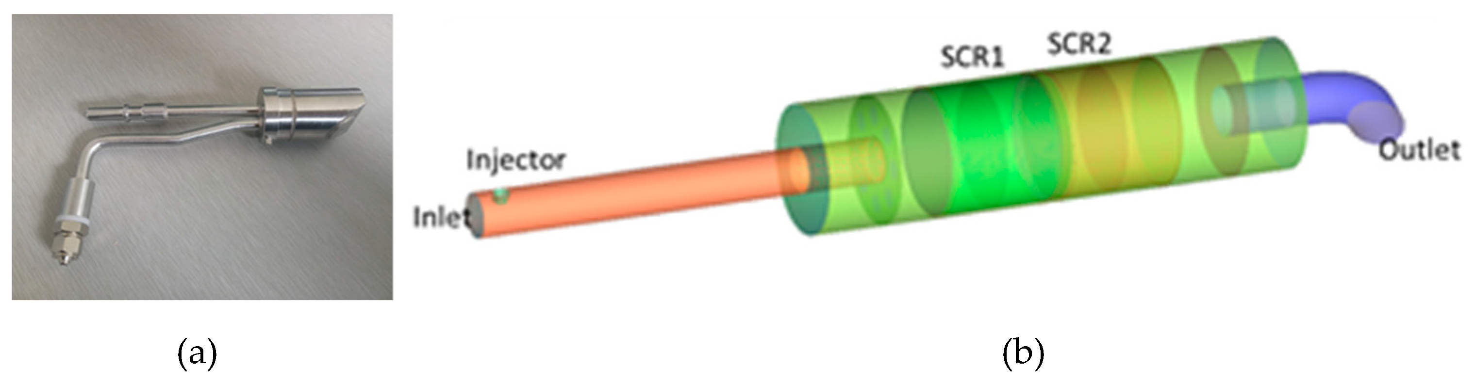
Figure 1 shows an air-assisted adblue nozzle, and the structure of the SCR system of the diesel vehicle. Generally the air-assisted injection system can be divided into the external mixing type and internal mixing type: the external mixing type breaks and atomizes the urea aqueous solution through the impact of the high-speed air flow; the internal mixing type mixes the compressed air into the mixing chamber and mixes with the urea aqueous solution. After the bubble leaves the nozzle, it expands rapidly due to the pressure difference between the internal and external environments, and the breakage of the bubble can for example promote the atomization of the droplet [
13]. The air-assisted injection system can achieve a good atomization effect, and it is more convenient and reliable to apply it on the vehicle diesel engine because of the self-contained compressed air on the real vehicle. Therefore, the research object of this paper is determined as an air-assisted adblue nozzle, and it’s an internal mixing type.
When the adblue injection system is working, the diaphragm pump draws in a fixed amount of urea aqueous solution, and pushes the urea aqueous solution at a fixed frequency under the action of the controller; the compressed air is depressurized, enters the mixing chamber and mixes with the urea aqueous solution, before finally being sprayed into the exhaust pipe through the nozzle. For this pneumatic atomizing nozzle, the atomization process is mainly divided into two processes: primary crushing and secondary crushing: (1) When the liquid exists in the form of a liquid column, the movement of the airflow can cause the unstable fluctuation of the gas-liquid interface, resulting in the instability and rupture of the liquid column, followed by the first break, which forms a larger droplet; (2) The large droplet continues to deform and rupture under the action of the air stream, generating a large number of small droplets, which constitutes a secondary crushing process. The gas-liquid flow inside the nozzle has a great influence on the spray field outside the nozzle, and even directly determines the atomization effect [
13].
3. CFD Simulation and Model Selection
The Euler-Euler model is mainly used to deal with the flow problem of any multiphase, and it can be calculated that the volume fraction of each phase in the multiphase flow is its largest feature [
14]. Commercial software AVL (AVL List Company from Austria)-Fire includes three multi-phase flow models based on the Euler-Euler method, namely the multi-fluid model, homogeneous model and VOF (Volume-of-Fluid Model) model. Among them, the homogeneous model has the lowest precision, which assumes that all phases are uniformly mixed, so only one momentum equation needs to be solved. The VOF model can be used to track the interface of two or more mutually incompatible fluids. In Fire, the VOF equation must be solved by high-order discrete equations. The dependence on the grid is too high. The multi-fluid model requires a complete calculation of the conservation equations for all phases, which represents the basic principle of the Euler-Euler method [
15]. In view of the accuracy of the multi-fluid model and the low grid dependence, this paper uses the multi-fluid model to simulate the gas-liquid two-phase flow in the nozzle.
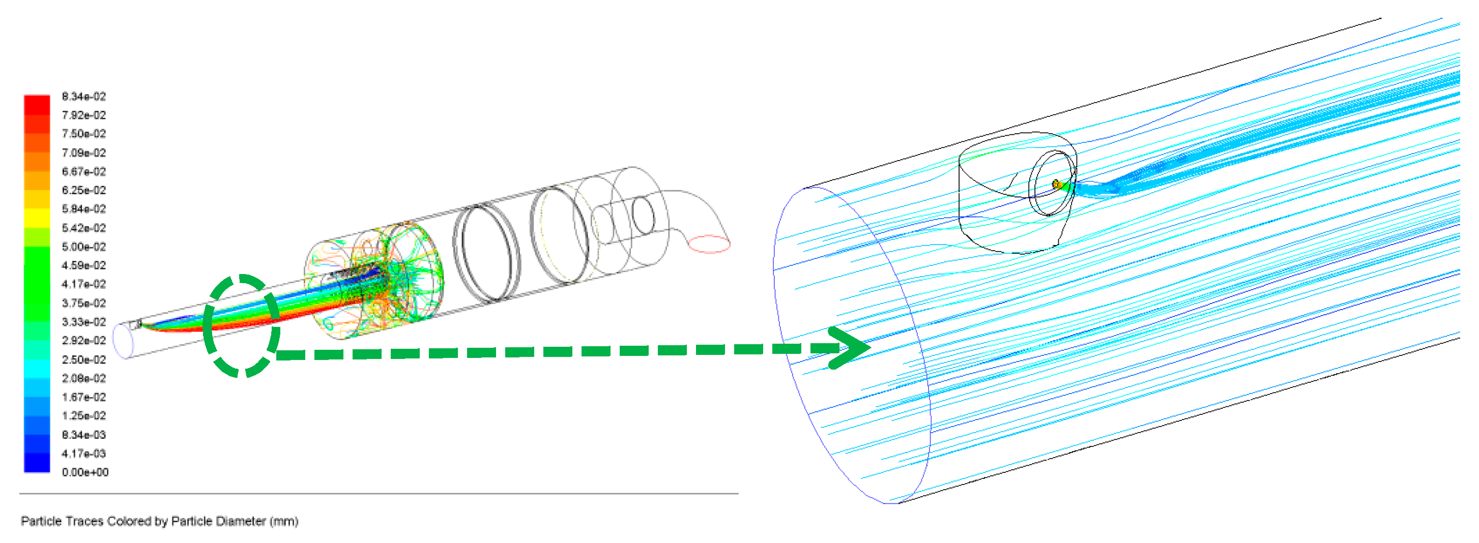
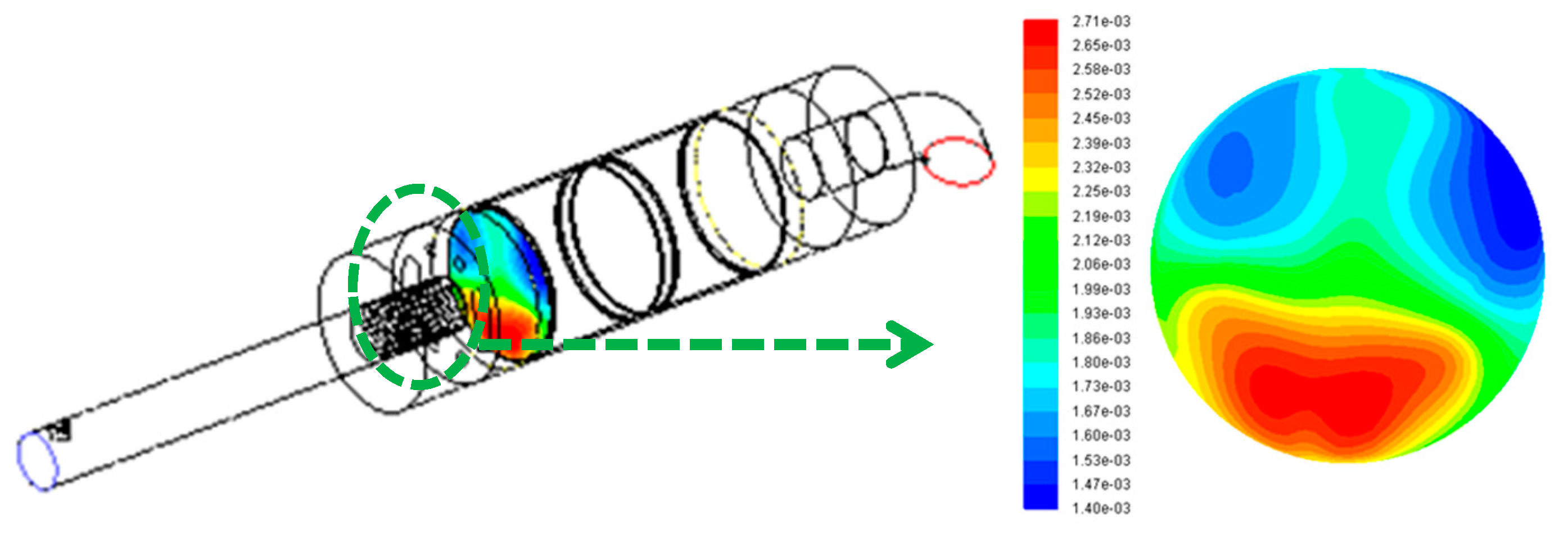
In order to achieve the simulation of the primary fracture, it is necessary to study the fluid properties at the near orifice and the interaction between the gas and liquid phases. In the area far from the nozzle, the Euler/Lagrangian method (DDM dispersion phase model) is used to describe the movement trajectory of the droplet by integrating the motion equation of a large number of particles. Under the specific nozzle structure and operating conditions, the two-phase flow simulation results in the nozzle can provide relevant information at the nozzle outlet, including the fluid velocity, turbulence intensity and mass fraction of each phase. The hole characteristics in the nozzle can also be accurately captured. For the transient calculation of the multiphase flow in the nozzle, select the data of the nozzle at any position and time step, and perform a linear interpolation when calling, for example [
16].
The simulation results of the two-phase flow in the nozzle based on the Euler/Eulerian method can be combined with the spray field simulation based on the particle group trajectory through the nozzle interface form, that is to say the former as the boundary condition of the latter. At the nozzle interface, the fluid data, including the fluid velocity, density, and turbulent energy, are transmitted smoothly. The benefits of this combination are: providing more accurate and reliable initial injection conditions: the injection speed and spray cone angle; and obtaining detailed nozzle exit data, including the turbulent kinetic energy and cavitation volume, for a more accurate primary fracture model.
3.1. Droplet Breakage
After the urea aqueous solution is sprayed from the nozzle, the primary crushing and secondary crushing will occur in the exhaust pipe, and will collide and merge with each other under the action of the turbulent diffusion and pulling, accompanied by the simultaneous droplet breaking process, evaporation and wall-impacting process. Theoretically, the order in which the droplets are broken is that the firstly are broken first, followed by the secondary broken. There are many models for simulating droplet breakage, based on different physical backgrounds and numerical algorithms. In general, most models have the size of the initial droplet set within the diameter of the orifice, while for nozzles with a sharp corner structure the initial droplet can be appropriately reduced due to the action of the cavity. This paper mainly studies the cold atomization process of the internal and external spray fields of SCR adblue nozzles. Therefore, only the primary crushing and secondary crushing models are introduced in detail.
3.1.1. Primary Fracture Model
How to identify and quantify the fracture mechanism of the urea aqueous solution is the main problem that needs to be solved to simulate the atomization process. In recent years, domestic and foreign scholars have carried out a large number of spray tests, which have promoted the research progress of the relevant physical processes at the nozzle exit. For different nozzle structures and operating conditions, the study of the fluctuation process of the surface of the liquid core and the influencing factors of the primary fracture is of great significance for understanding the fracture mechanism.
During the flow inside the nozzle, the intensity and frequency of the fluid fluctuations cause a change in the turbulent velocity, causing the formation, development and collapse of the gas core or gas vacuoles, and accelerating the subsequent collapse of the liquid core. The diffuse phase model (DPM) contains two forms of primary fracture: the independent model is used to calculate the erosion of the liquid core, and the primary fracture occurs on the surface of the liquid core. The main feature of the method is that the initial droplet size is smaller than the orifice. The mechanism is therefore different from the first method.
In general, the primary fracture model must be used in conjunction with the secondary fracture model, and the order is sequential. For the DPM simulation method, the criteria for the primary fracture to secondary fracture are the Weber number and the minimum droplet diameter of the droplet. In this paper, the initial crushing model of Blob Injection is used to simulate the primary crushing process of droplets by simulating the phenomenon of cavity and aerodynamics in the nozzle.
3.1.2. Secondary Fracture Model
In this paper, the TAB model is used to simulate the secondary crushing process of droplets. Based on the theory of elastic mechanics, the model is subjected to various forces in the movement, so that the droplet itself vibrates and twists like an elastomer. When the deformation occurs to a certain extent, it will break. The aerodynamic forces in the spray field, the surface tension of the droplets, and the droplet viscosity are similar to the external forces, elastic forces, and damping forces in the mass spring system, respectively [
17].
The mother droplet oscillates in the direction of the injection axis, and if that is the case, the mother droplet breaks into smaller droplets. The normal velocity of the sub-droplet is approximately equal to the vibration velocity at the time of the fracture, and at the same time the model can automatically calculate the spray cone angle. Through the energy conservation equation, the Sauter mean diameter of the sub-droplet can be calculated. The calculation result of the droplet radius constitutes the chi-square distribution of the droplet size, and the actual droplet size can be randomly selected from [
18]. For the ratio of the mother droplet to the sub-droplet radius, the larger the value is, the smaller the diameter of the sub-droplet is.
3.2. Droplet Evaporation and Urea Decomposition
This paper uses the Multi-Component model to describe the droplet evaporation process, including urea pyrolysis.
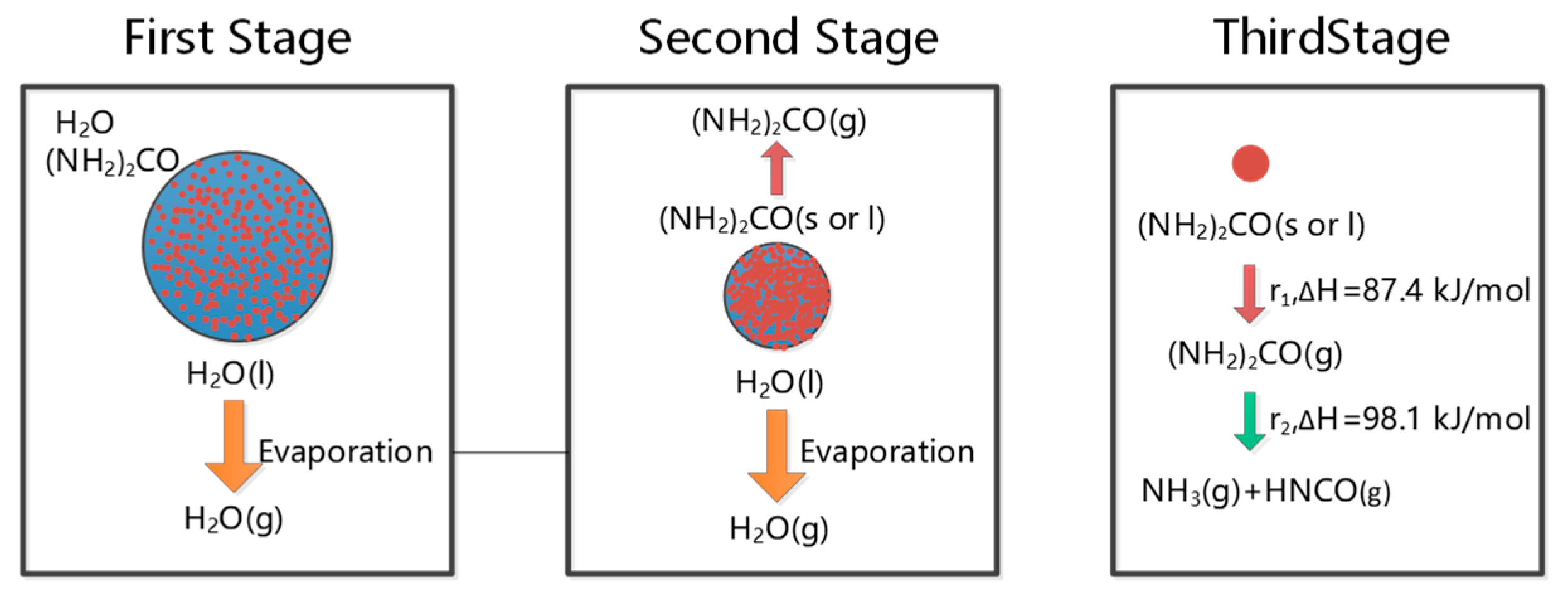
Figure 2 is a schematic illustration of the droplet evaporation and urea pyrolysis. As can be seen from
Figure 2, the urea droplets injected into the exhaust pipe are gradually heated by the exhaust gas, and the droplets begin to evaporate as the temperature rises. Since the boiling point of water is low, the water in the aqueous urea solution begins to evaporate at the earliest point in time. Urea can be directly pyrolysized from the solid or liquid phase, so the presence or absence of an intermediate product, urea vapor, is still unknown, i.e., Stage II in
Figure 2 is negligible.
The water vapor pressure on the surface of the droplet can be obtained through the modified formula of Perman and Lovett [
19], which is used to calculate the evaporation rate of water. According to Birkhold’s theory [
13], wall membrane evaporation is divided into two phases: (1) evaporation of water from the urea aqueous solution; and (2) when the mass fraction of water in the urea aqueous solution is under 5%, urea begins to pyrolysize. The thermal decomposition of urea mainly considers the following chemical reaction equations:
The pyrolysis rate can be expressed as:
where
A is the frequency factor,
Ea is the reaction activation energy,
T is the wall film temperature, and
Dfilmthick is the wall film thickness. This paper uses the kinetic parameters recommended by Kim [
20], as shown in
Table 1.


