Article

Microstructures and Wear Resistance of CoCrFeNi2V0.5Tix High-Entropy Alloy Coatings Prepared by Laser Cladding

1
Key Laboratory of Solidification Control and Digital Preparation Technology (Liaoning Province), School of Materials Science and Engineering, Dalian University of Technology, Dalian 116024, China
2
College of Mechanical and Electronic Engineering, Shandong University of Science and Technology, Qingdao 266590, China
3
New Materials Innovation Center, Ningbo Institute of Dalian University of Technology, Ningbo 315000, China
*
Author to whom correspondence should be addressed.
Crystals 2020, 10(5), 352; https://doi.org/10.3390/cryst10050352
Submission received: 2 April 2020 / Revised: 24 April 2020 / Accepted: 28 April 2020 / Published: 29 April 2020
(This article belongs to the Special Issue Development of High Entropy Alloys)

Abstract

:
CoCrFeNi2V0.5Tix high entropy alloy coatings were synthesized by laser cladding on Ti-6Al-4V (annotated as TC4) substrate. The microstructures, hardness, and wear properties of the coatings were studied in detail. The results showed that these coatings were all composed of body-centered cubic (BCC) solid solution, (Co,Ni)Ti2 phase, and Ti-rich phase. With the increase of Ti content (x in the range of 0–1.0), the hardness of these coatings (about 960 HV) was basically unchanged and stabilized, whereas, when x was increased to 1.25, the correspondent hardness was decreased significantly to about 830 HV. Compared with original substrate, the wear resistance of high-entropy alloy (HEA) coatings was greatly improved. In particular, CoCrFeNi2V0.5Ti0.75 (donated as Ti0.75) exhibited the lowest wear rate, width, and depth of tracks of wear, indicating the best wear resistance. Moreover, the wear mechanisms of Ti0.75 coating were mainly adhesive wear and oxidative wear.

1. Introduction

The titanium alloys with low density, high specific strength, and good high temperature properties play a crucial role in many fields, especially aerospace and weapons [1]. For example, as one of the widely used titanium alloys, Ti-6Al-4V titanium alloy (TC4 alloy) can work for a long time at 400 ℃. The elastic modulus of TC4, E = 110 GPa, is about half of that of steel and its specific strength is 13.5 N/m2. The total amount of TC4 alloy used in aircraft structural materials can reach 80% of the total amount of titanium alloy. However, owing to the poor wear resistance, the industrial application of the TC4 titanium alloy is still greatly limited [2,3]. Thus, it is important to improve the surface properties of TC4 titanium alloys to meet the requirements in various complex service environments and broaden their application range.
Up now, the materials usually used for surface modification of titanium alloys are mainly concentrated in intermetallic compounds [4,5], oxides [6,7], ceramic materials [8,9], and composite powders [10,11]. With the development of materials science and technology, high-entropy alloys (HEAs) have received widespread attention owing to their four unique effects: high entropy effect, lattice distortion effect, sluggish diffusion effect, and cocktail effect. Compared with the traditional alloys, HEAs surprisingly exhibit excellent comprehensive properties, such as high strength and hardness, good abrasion resistance, excellent corrosion resistance, and superior high temperature stability, among others, which can meet the requirements of more complex and difficult service environments [12,13,14,15,16,17]. For instance, the AlCoCrFeNi2.1 eutectic high-entropy alloy (EHEA) with a fine dual-phase lamellar microstructure showed excellent corrosion resistance for ship propellers and in the wrought state, with ultrahigh strength equivalent to maraging steel for structural applications [18]. The Co1.5CrFeNi1.5Ti and Al0.2Co1.5CrFeNi1.5Ti HEAs not only exhibited excellent wear resistance, the value of which was more than twice that of traditional wear resistant steel (SUJ and SKH51 wear-resistant steel), but also have excellent high temperature resistance and oxidation resistance [19,20]. Therefore, HEAs have huge potential value and application prospect.
In recent years, studies on surface modification through HEAs have gradually emerged because the high entropy alloy coatings can also exhibit excellent comprehensive properties. The methods of surface modification mainly include magnetron sputtering [21], laser cladding [22,23], thermal or cold spraying [24], spark plasma sintering [25], and so on. Among them, laser cladding has been intensively investigated and used owing to its unique features such as high heating speed, low dilution rate, small heat affected zone, fewer coating defects, and good metallurgical bonding between the cladding layer and substrate [26]. Qiu et al. [27] reported that the Al2CrFeCoCuTiNix coatings were successfully prepared on Q235 steel substrate. The study indicated that the coatings were consisted of body-centered cubic (BCC) and face-centered cubic (FCC) phase and its microhardness could reach 1102 HV. With the increase in Ni content, its wear resistance gradually increased and the corrosion resistance increased first and then decreased. Liang et al. [28] synthesized AlCrFeNi2W0.2Nbx high-entropy alloy coatings by laser cladding on 304 stainless steel substrate. The wear resistance of the 304 stainless steel was drastically improved and the wear rate of the coating was one-tenth of that of the substrate under the condition of dry friction. Juan et al. [29] studied the microstructure and wear resistance of FeCrCoNiAlMox high entropy alloy coatings by laser cladding on 45# steel. The results showed that the FeCrCoNiAlMo1.0 HEA coating displayed the highest microhardness and smallest wear rate. Zhang [30] et al. synthesized the TiAlNiSiV high entropy alloys coatings on the TC4 substrate by laser cladding. The coatings mainly consisted of (Ti,V)5Si3, NiAl, and TiN; the hardness was up to 1151∼1357 HV; and the coatings showed outstanding wear resistance, nearly the 4–6 times as much as the substrate. Although available literature has been dedicated to the investigation of titanium alloy substrate, the research is still rare. Therefore, it is necessary to conduct research on surface modification of titanium alloys with high entropy alloys. It has certain reference significance for the combined use of two dissimilar metals, high-entropy alloy and titanium alloy.
Our previous study revealed that the as-prepared CoFeNi2V0.5Nbx HEAs exhibited excellent mechanical properties, for example, with the increase of Nb content from x = 0 to x = 1, the hardness increased from 133.4 HV to 687.7 HV, accompanied by the increase in yield strength from 172 MPa to 2108 MPa [31]. In the present study, to further enhance the mechanical properties of alloy and achieve the good combination between the coatings and the substrate, the CoFeNi2V0.5Nbx composition was selected and correspondingly adjusted. The Nb element was replaced in the CoFeNi2V0.5Nbx with the Ti element to achieve the good combination between the coatings and the substrate. In addition, the crystal structure of hexagonal Ti was close to that of the face-centered cubic structure (FCC) for the lattice constant of c was close to a, which means the Ti alloys show good ductility [32]. Thus, the addition of Ti also can improve the strong plasticity of coatings. In addition, Cr element was added in CoFeNi2V0.5Nbx alloys to form a new high-entropy alloy system CoCrFeNi2V0.5Tix to further increase the hardness.
Thus, in this paper, the CoCrFeNi2V0.5Tix high-entropy alloy coatings were designed and synthesized on TC4 substrate by laser cladding. The effects of Ti content on the phase, microstructures, and wear resistance of CoCrFeNi2V0.5 alloy coatings were also investigated.

2. Materials and Methods

In this study, TC4 titanium alloy was selected as the substrate material with the dimension of 80 × 15 × 8 mm3. The nominal composition of the TC4 titanium is shown in Table 1. The surface of the substrate was grounded using the SiC emery paper from #80 to #600, and subsequently ultrasonic cleaned with alcohol for 20 min to remove the oil and dirty. Meanwhile, the CoCrFeNi2V0.5Tix (x = 0, 0.5, 0.75, 1.0, and 1.25, donated as Ti0, Ti0.5, Ti0.75, Ti1.0, and Ti1.25) alloy powders were prepared by mixing high purity (≥99.95%) elemental powders whose powder granularity was approximately 75 μm. Firstly, the powder was weighed as a nominal component using a precision balance with an accuracy of 0.0001 g. Secondly, the alloy powder was mechanically blended using corundum ball mill pots and milled by the planetary ball for 1 h with a constant rotation speed of 175 rpm. To prevent the oxidization of powder caused by overheating during the milling process, the milling process paused every 30 min for stopping 5 min. In addition, the substrate materials and mixed powder should be dried and preheated for two hours in a vacuum oven at temperature of 100 ºC, which could not only reduce the temperature difference between the substrate and the powder, but also reduce the possibility of coating crack initiation. In this paper, the preset powder method was used for laser cladding because this method is not only simple to operate, easy to implement, and low in cost, but also does not have high requirements for cladding materials. The thickness of the preset layer was 0.8 mm. The HEA coatings were fabricated by a CO2-type laser processing machine (LWS-500, Laserline, Koblenz, Germany) with a wavelength of 10.6 μm. The cladding process was operated with laser power of 800 W, scanning speed of 5 mm/s, and spot diameter of 3 mm. During the laser cladding process, the high purity argon with a flow rate of 5 L/min was injected as shielding gas to prevent the oxidation of molten metals.
Samples with a dimension of 8 × 15 × 8 mm3 were taken along the direction perpendicular to the laser scanning. Then, the samples were polished and etched with aqua regia (HCl:HNO3 = 3:1) diluted by alcohol. The phase composition of the coating was analyzed by X-ray diffraction (XRD, EMPYREAN, Almelo, Holland) at a scanning speed of 0.22 °/s, ranging from 20° to 100°, with Cu Kα radiation at 40 kV and 40 mA. Scanning electron microscopy (SEM, Zeiss Supra 55, Zeiss, Oberkochen, Germany) with energy spectrum analyzer (EDS) was used to observe the microstructure of the coatings. The composition analysis of samples was measured after being mechanically grounded and polished by electron probe microanalysis (EPMA, JXA-8530F, JEOL, Japan).
The microhardness of the coatings was measured by the Vickers hardness tester (MH 50, Shanghai Everyone Precision Instruments CO. LTD, China) with a load of 9.8 N and a duration time of 15 s. Every 100 μm in the cross section along the top of the coating to the substrate was tested. Each sample was tested at least five times at each position to avoid accidental results. The dry sliding wear test of coatings and substrate was tested using a sliding wear tester (CFT-I, Zhong Ke Kai Hua Corporation, Lanzhou, China) at room temperature with reciprocating friction, and the distance was 5 mm. The Si3N4 ball with diameter of 4 mm, Vickers hardness of 1500 HV, and Ra ≤ 0.1 μm was chosen as counterpart. The wear tests were conducted at room temperature with a normal sliding speed of 67 mm/s for the total sliding time of 15 min of each test and under the load of 15 N. At least three parallel tests were performed for each sample to ensure the reliability of experimental data. After the friction test, the depth and width of the tracks of wear were measured using a confocal laser scanning microscope (LEXT OLS4000, Olympus, Tokyo, Japan). Every sample was repeatedly measured at least three times and, finally, they were taken as the average to calculate the wear rate using the following formula [33]:
δ = Δ V F L
where δ, ΔV, F, and L stand for the wear rate, the volume loss, loading, and total wear distance, respectively. In addition, the microscopic appearance of worn surfaces was observed using scanning electron microscopy (SEM).

3. Results and Discussion

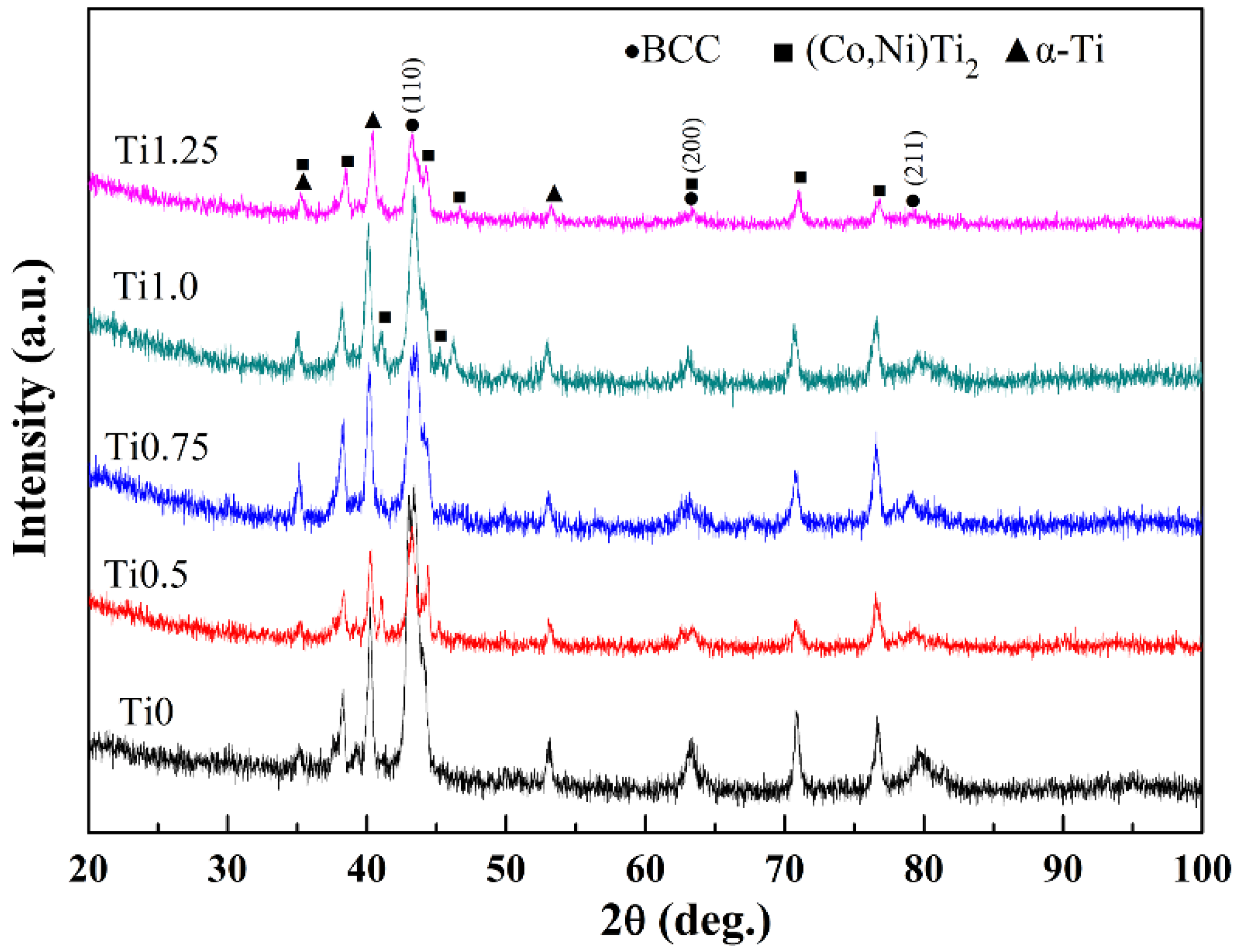
3.1. Phase Structures

Figure 1 depicts the XRD patterns of CoCrFeNi2V0.5Tix HEA coatings. There are three different types of diffraction peaks, namely, BCC solid solution, (Co,Ni)Ti2, and Ti-rich phase, respectively. The mixing enthalpy is one of dominated factors when predicting the high-entropy alloy phase. The following formula is usually used to calculate the mixing enthalpy of the HEAs system according to the known binary data from [34,35].
Δ H m i x = i = 1 , i j N 4 Δ H i j m i x c i c j
where ci and cj are the molar content of the ith and jth component, respectively; i = 1 n c i = 1 ; and Δ H i j m i x is the enthalpy of mixing for the binary ith and jth elements. The Gibbs free energy of mixing can be calculated by the formula Δ G m i x = Δ H m i x T Δ S m i x [14]. For HEAs, the high entropy effect of HEAs can reduce the Gibbs free energy of the system if the Δ H m i x remains constant. It is well known that the difference of Gibbs free energy is the driving force for the formation of intermetallic compounds. Thus, it was easier for the HEAs to form a solid solution phase, so as to reduce the number of phases. From the (110)BCC peaks, the calculated lattice parameter (a) of BCC solid was 2.941 ± 0.004 Å, 2.950 ± 0.007Å, 2.947 ± 0.002 Å, 2.944 ± 0.005 Å, and 2.949 ± 0.008 Å for Ti0, Ti0.5, Ti0.75, Ti1.0, and Ti1.25, respectively. According to the mixing enthalpy between the elements given in Table 2, it can be seen that the mixing enthalpy between Ni, Co, and Ti elements is the most negative, at −35 kJ/mol and −28 kJ/mol, respectively, thus the (Co,Ni)Ti2 phase can be formed. Moreover, it is found that, although (Co,Ni)Ti2 is an intermetallic compound, it is an FCC stable structure with Ti as the matrix, and it possesses metallic anisotropic nature and would behave as a ductile material [36,37]. As the Ti content increases, the phase structure does not change, but the number of the diffraction peaks of the (Co,Ni)Ti2 phase increases, so it is speculated that the corresponding volume fraction of the (Co,Ni)Ti2 phase increases.

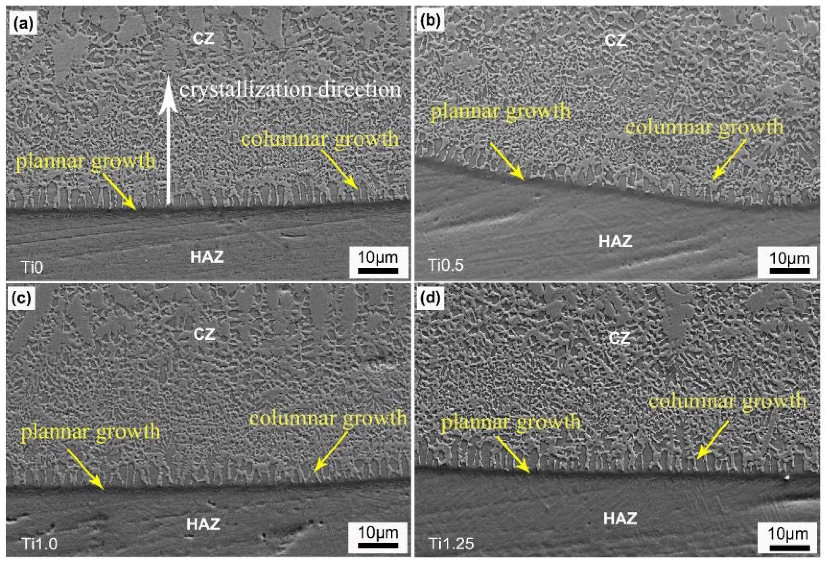
3.2. Microstructures
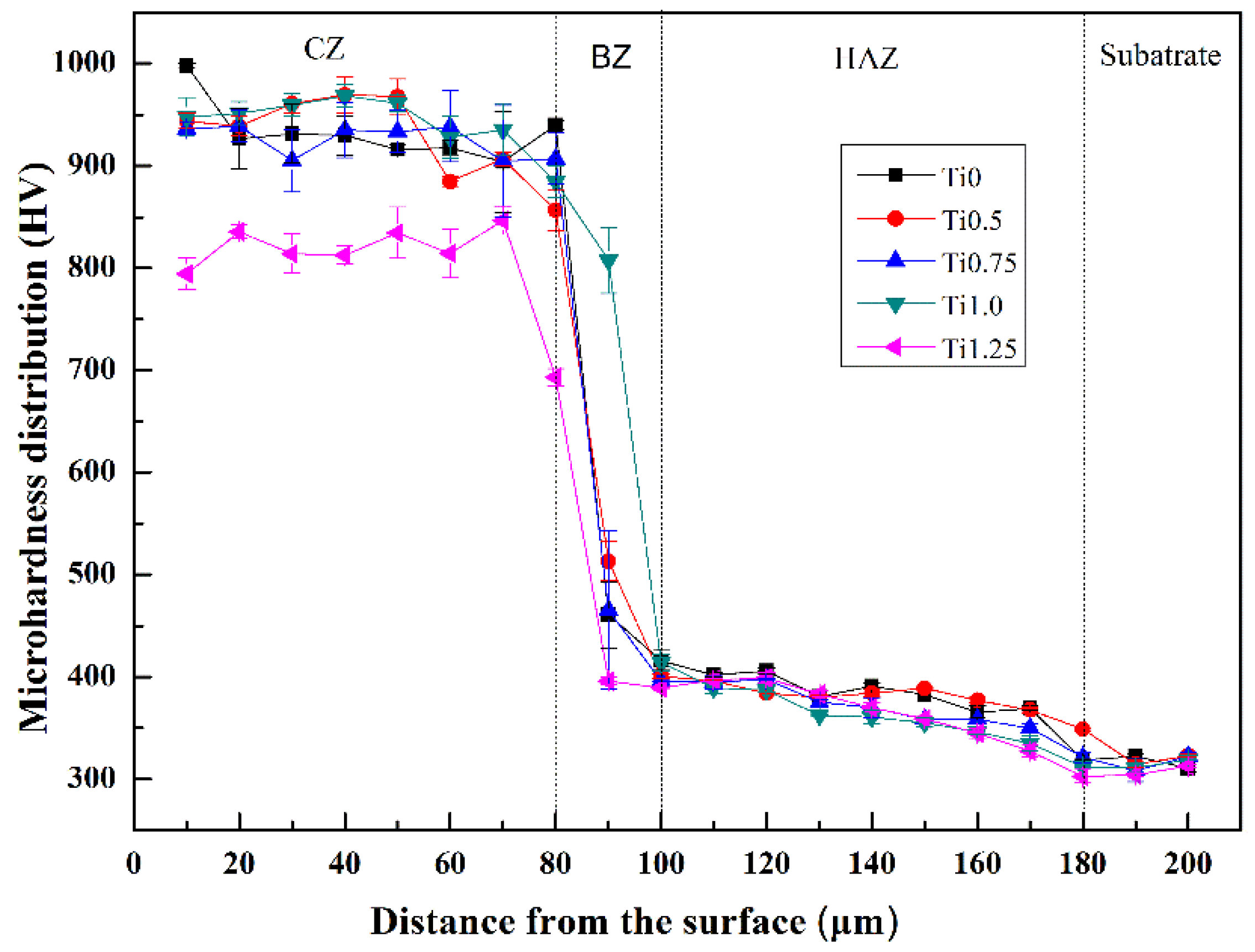
Figure 2a–e illustrate the cross-sectional micrographs of CoCrFeNi2V0.5Tix coatings, which are mainly composed of the cladding zone (CZ), bonding zone (BZ), and heat-affected zone (HAZ) [28]. A clear boundary marked with dotted lines between the coating and the heat-affected zone can be found in Figure 2a. The calculated dilution rates (η) of CoCrFeNi2V0.5Tix alloy coatings according to the formula η = h h + H are 35.75%, 36.81%, 33.16%, 32.56%, and 33.98%, respectively, where η is the dilution rate, H is the height of the cladding layer, and h is the depth of the molten pool [38]. For the convenience of study, the CoCrFeNi2V0.5 sample is taken as the representative for line-scanning analysis. The corresponding results are shown in Figure 2f. The elements that originally belong to the cladding layer are also detected in the substrate. Besides, although titanium is not added to the cladding material for Ti0 coating, a large amount of Ti element is detected in the coating. This is because, under the action of high-energy laser, the cladding powder and the surface layer of the TC4 substrate melt and can accelerate the convection in the formed molten pool. That is to say, element inter-diffusion can occur between the coating and the substrate, thus promoting a good metallurgical bond between the coating and substrate.
Figure 3 displays the micrographs of the bonding zones of the CoCrFeNi2V0.5Tix HEA coatings. As shown in Figure 3a, the microstructures of the bonding zones of the coatings change from planar crystal to columnar crystal and dendritic crystal from the bottom of the bonding zone to the cladding zone. As is well known, the growth of the crystal is closely related to the ratio of the temperature gradient (G) and the solidification rate (R) [39]. At the bottom of the molten pool, the value of G/R is relatively large, caused by the large temperature gradient (G) and small solidification rate (R), thus it is difficult to form constitutional supercooling. On the other hand, the substrate is heated to semi-molten state to serve as nucleation particle near the fusion zone, resulting in a greater nucleation rate than the growth rate in this region, so the planar growth occurs. Along with the advancement of the solid–liquid interface, the ratio of G/R gradually reduces, and the solute concentration (C0) increases, so the constitutional supercooling occurs relatively easily, resulting in the evolution from planar to columnar crystal. In addition, owing to the largest temperature gradient (G) and the fastest heat dissipation in the vertical interface direction marked with a white arrow, the grains grow optimally to form columnar crystals along the vertical interface pointing toward the center of the molten pool [40]. Near the center of molten pool, the value of G/R is at the minimum, the solute concentration (C0) is at the maximum, and the constitutional supercooling is at the maximum, so the microstructure gradually transforms into dendritic morphology [41].
The microstructure of the middle parts of the CoCrFeNi2V0.5Tix coatings is shown in Figure 4. With the increase of the Ti content, the microstructures of the coatings change significantly. Note that all coatings consisted of three zones, marked as A, B, and C, respectively. The chemical compositions of the A and B regions are listed in Table 3. The result indicates that region A is enriched in Fe, Cr, and V elements, while region B is mainly enriched in Co, Ni, and Ti elements. In addition, in order to further intuitively disclose the element distribution between phases, EPMA mapping of Ti0.5 was performed, as seen in Figure 5, and the results indicated the element distribution of coatings was consistent with the EDS results. On the basis of on the XRD results, it could be reasonably concluded that the A, B, and C regions represent BCC solid solutions, (Co,Ni)Ti2, and Ti-rich phase, respectively. In addition, the volume fraction of the B region increases gradually, suggesting that the content of (Co,Ni)Ti2 increases, which is consistent with the XRD results. During solidification, Cr and V elements with higher melting points first lead to formation of BCC solid solution. Soon afterwards, a part of Ti and Fe elements with relatively lower melting points, which are all BCC structures, is absorbed around the Cr and V phases, and gradually dissolved into the BCC phase. At the same time, the relatively negative mixing enthalpy between Co, Ni, and Ti elements leads to large interatomic attractive force, thus Co and Ni elements are adsorbed around the remaining Ti-rich phases forming a (Ni,Co)Ti2 phase. In this process, theoretically, as Fe and Cr are β-Ti stabilizing elements, they can stably exist in the BCC phase structure. However, the atomic radius of the Ti element is much larger than that of other constituent elements of alloy coatings. It is easy to reach a saturated state of solid solution. Thus, the β-Ti adsorbed on the BCC is not completely dissolved into the BCC. Subsequently, the part of Ti that did not dissolve into BCC gradually decomposed to form the α-Ti phase. Therefore, the black Ti-rich phase observed in Figure 4 is precipitated along the BCC matrix instead of intermetallic compounds. In addition, with the increase of Ti content, the morphology of the C region changes from round to needle-like shape. In addition, the volume fraction of (Co,Ni)Ti2 phase of coatings was estimated and quantified based on the SEM image in low magnification by Image Pro Plus. The calculated volume fraction of coatings was 51.67%, 53.89%, 54.65%, 55.36%, and 59.12% for Ti0, Ti0.5, Ti0.75, Ti1.0, and Ti1.25, respectively. Thus, the volume fraction of (Co,Ni)Ti2 increased with the increase of Ti content.

3.3. Microhardness

Figure 6 illustrates the microhardness of the CoCrFeNi2V0.5Tix HEA coatings from the top surface to the substrate. It can be intuitively seen that the microhardness curve of the coatings is divided into four parts, the cladding zone, bonding zone, heat-affected zone, and substrate, respectively. Moreover, the microhardnesses of all these coating are significantly higher than that of the TC4 substrate, which is almost 2.6–3.0 times than that of the substrate. The higher hardness of these alloy coatings may be attributed to two aspects. First, some Ti and V elements with large atomic radius dissolved into the BCC solid solution phase could cause severe lattice distortion, and thus enhance the solid solution strengthening effect [42]. Then, the hard Ti-rich phase is almost distributed on the BCC matrix phase, resulting in the second phase strengthening. When x is in the range of 0–1.0, the hardness of the alloy coatings almost does not change. However, when the Ti content increases to x = 1.25, the hardness decreases obviously. In the Ti1.25 alloy coating, the decrease of hard BCC phase volume fraction and increase of soft (Co,Ni)Ti2 phase volume fraction lead to the decrease of the hardness. Cai et al. [43] reported that the hardness of the NiCrCoVTi HEA coating prepared by laser cladding on TC4 alloy could reach up to 700 HV, which is still lower than our results. Recently, Xiang et al. [44] synthesized the CoCrFeNi coating on pure titanium substrate by pulsed laser cladding and the hardness of the CoCrFeNi coating reached 800 HV. It can be speculated via such a comparison that our CoCrFeNi2V0.5Tix HEAs coatings prepared on the TC4 alloy exhibit better properties.

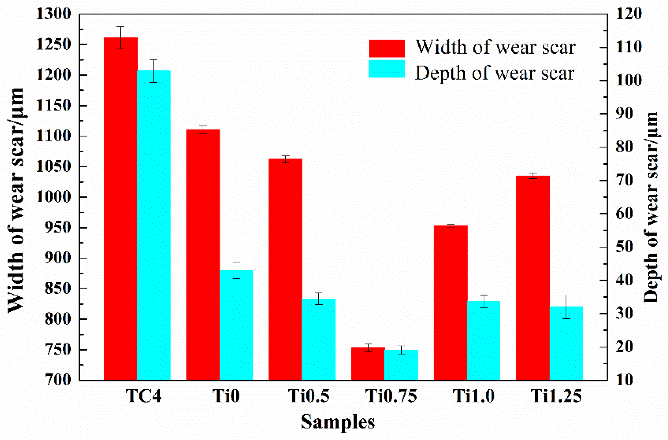
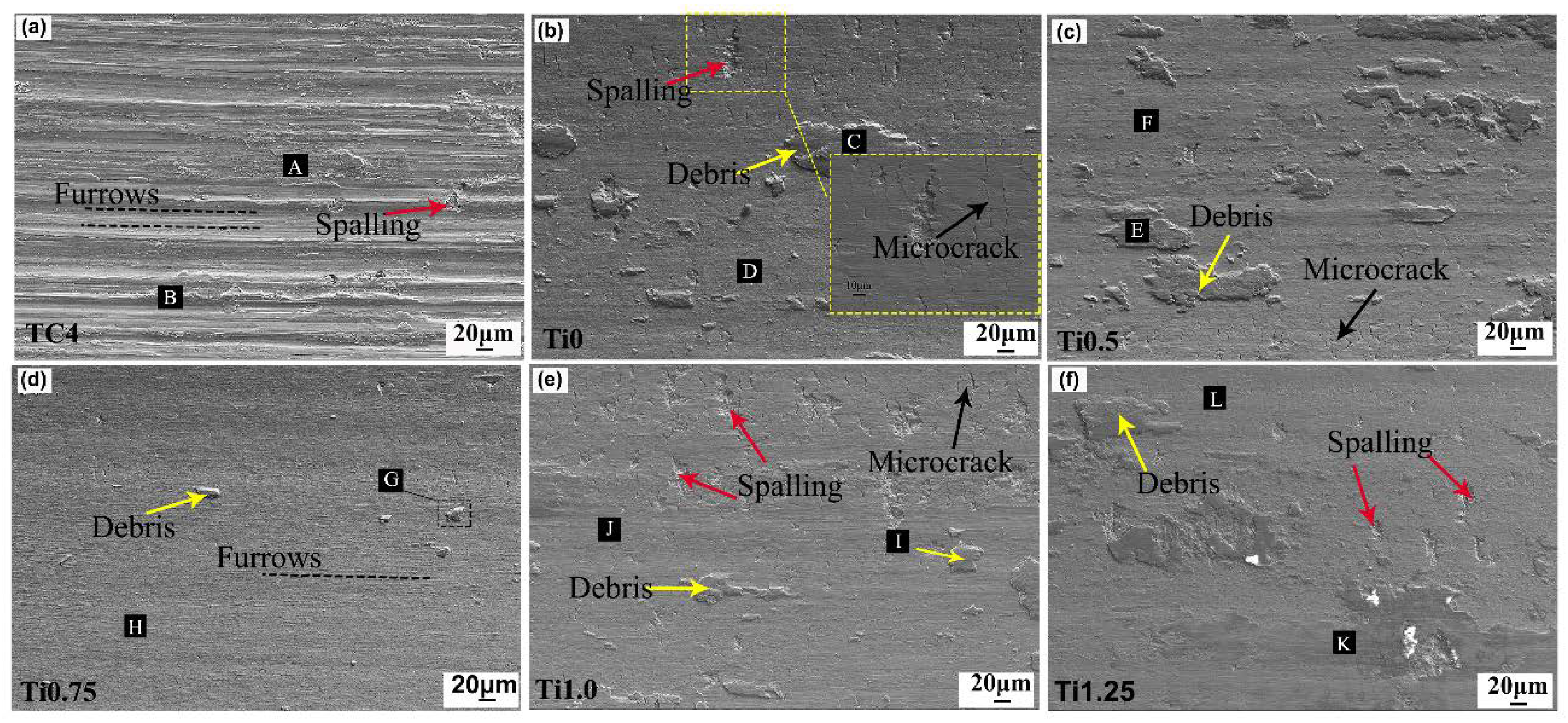
3.4. Wear Resistance

In order to evaluate the wear properties of CoCrFeNi2V0.5Tix HEA coatings, the wear resistance tests are carried out on the coatings and TC4 substrate. The width and depth of tracks of wear are shown in the Figure 7. It can be seen that the width and depth of the tracks of wear of the CoCrFeNi2V0.5Tix coatings are significantly lower than that of the substrate, where the CoCrFeNi2V0.5Ti0.75 coating has the minimum value. Then, the wear rate is used to characterize the wear resistance of the coating, and the calculated wear rates of the substrate and coatings are shown in Figure 8. When x is less than 0.75, the wear rate of coatings decreases gradually, and when x is larger than 0.75, the wear rate increases. This indicates that the wear resistance of the coating increases first and then decreases. The CoCrFeNi2V0.5Ti0.75 HEA coating exhibits the minimum wear rate of 4.426 × 10⁻⁵ mm3/(N·m), meaning that it has the best wear resistance.
Combined with the XRD and SEM results, it can be known that the coating is mainly composed of three phases, namely, BCC, (Co,Ni)Ti2 phase, and Ti-rich phase. The hard BCC phase plays a supporting role to avoid a lot of abrasive wear, while the soft (Co,Ni)Ti2 phase can avoid the crack propagation. Hence, the coupled interaction of the hard BCC phase and the ductile (Co,Ni)Ti2 phase determines the wear resistance of the coating [23]. When 0 < x < 1.0, the hardness fluctuation of the coating is small, but the wear resistance shows a significant difference. Although the hardness values of Ti0 and Ti0.75 are not much different, the wear resistance of Ti0.75 is obviously better than that of Ti0, which can be attributed to their different microscopic morphology. As can be seen from Figure 4 (b), some hard phase in Ti0 is distributed in the grain boundaries, causing a certain concentration of stress. During friction and wear, cracks occur easily, so Ti0 shows poor wear resistance. According to Archard’s law, the wear resistance of a material is positively related to hardness, but high hardness will also increase the brittleness of the material, causing the wear resistance to decrease instead [45]. The hardness value of Ti0.5 and Ti1.0 is relatively high, which increases the brittleness of the coatings, which makes its exhibit low wear resistance [27]. When x reaches 1.25, not only does the volume fraction of the (Co,Ni)Ti2 phase with good plasticity significantly increase, the Ti-rich phase also becomes coarse needle-shaped, as seen in Figure 4j, which causes the hardness to decrease obviously. Thus, the Ti1.25 coating shows the worst wear resistance. This comparison indicates that Ti0.75 exhibits the best wear resistance, possibly owing to the optimal ratio of the hard and soft phases. In summary, among the CoCrFeNi2V0.5Tix HEA coatings, Ti0.75 shows the best wear resistance, which can also be proven by the microscopic morphology of the tracks of wear.
In order to analyze the wear mechanism of these alloy coatings and the substrate, micrograph and composition analyses of the tracks of wear are performed and the results are displayed in the Figure 9 and Table 4. From Figure 9a, obvious parallel furrow characteristics marked with dotted lines can be observed on the surface of TC4 substrate, indicating the occurrence of abrasive wear. For the TC4 sample, the hardness is nearly 320 HV, which is much softer than the friction pair, Si3N4. Therefore, during the friction process, the Si3N4 ball is embedded in the substrate and continues to cut it under the cyclic stress, and finally a furrow in the sliding direction is formed on the surface of the substrate [46]. There are also some spallings (marked with red arrows) that can be found on the worn surface, which indicates the occurrence of adhesive wear. Moreover, a high oxygen content is detected on the surface, indicating that the wear process is accompanied by oxidation reaction [47]. On the one hand, the chemical properties of Ti element are active, and it reacts easily with oxygen in the air to form an oxidation film during the friction process. On the other hand, the frictional heat generated by reciprocating sliding is also a factor of oxidative wear. As the friction process goes on, the oxidation film will soon form a new oxidation film after being worn off. Thus, the oxidation wear takes place in the whole wear process.
The worn surface of the Ti0 and Ti0.5 HEA coatings shown in Figure 9b,c attaches some plate-like debris (marked with yellow arrows). On the basis of the EDS result, the composition of the debris is similar to that of the coating, suggesting that the abrasive particles worn off from the coating are adhered to the wear surface under the combined action of cyclic loading and heat generated by friction. This represents that the dominated wear mechanism of the coating is adhesive wear. At the same time, some micro-cracks, marked with black arrows, which are the characteristics of brittle fracture, are distributed on the surfaces. There are also some spallings distributed on the surfaces. These may be attributed to the excessive hardness of the coating, and result in the degree of plastic deformation exceeding the threshold [48,49]. Moreover, combined with the EDS results, the oxidation phenomenon also occurs in the wear process, suggesting the existence of oxidative wear mechanisms.
Unlike the previous coatings, when x increases to 0.75, the wear surface changes smoothly with a few small adhered fragments and fine shallow furrows, indicating that this coating shows the best wear resistance. During the friction process, the hard BCC phase plays a supporting role to avoid a lot of abrasive wear. In addition, according to the previous description of the (Co,Ni)Ti2, which is a FCC stable structure and would behave as a ductile material [37]. Hence, the coupled interaction of the hard BCC phase and the ductile (Co,Ni)Ti2 phase makes this coating exhibit excellent wear resistance. In short, the main mechanism of Ti0.75 coating is adhesive, abrasive, and oxidative wear.
The wear surface morphology of the Ti1.0 coating is similar to that of the Ti0 and Ti0.5 coatings, which indicated that the wear mechanism of the Ti1.0 coating is mainly adhesive wear and oxidative wear. When the Ti content increases to 1.25, the coating shows the lowest hardness compared with others. Owing to the relatively low hardness of the abrasive particles, a large area flake debris adheres to the coating surface under repeated rolling of the friction pair, as shown in Figure 9f. The oxygen content in area K reaches 69.47 at. %, indicating that the debris has enough contact with the oxygen in the air during the wear process, proving the existence of oxidative wear.

4. Conclusions

The CoCrFeNi2V0.5Tix (x = 0, 0.5, 0.75, 1.0, 1.25) HEA coatings were successfully fabricated by laser cladding on the TC4 substrate. The results of microstructure, morphology, hardness, and wear resistance of the coatings are summarized as follows:
(1)
All of the CoCrFeNi2V0.5Tix alloy coatings are composed of Fe,Cr-BCC solid solution phase, (Co,Ni)Ti2 phase, and α-Ti phase. With the increase of Ti content, the volume fraction of the (Co,Ni)2Ti phase increases.
(2)
The microhardness of the CoCrFeNi2V0.5Tix alloy coating is significantly higher than that of the TC4 substrate, even 2.6–3.0 times higher than the substrate. The improvement is mainly attributed to second phase strengthening and solid solution strengthening.
(3)
The CoCrFeNi2V0.5Ti0.75 alloy coating exhibits the best wear resistance, and its wear rate is about 4.426 × 10⁻⁵ mm3/(N·m). The wear mechanism of all of the CoCrFeNi2V0.5Tix HEA coatings is mainly adhesive wear and oxidation wear, while the wear mechanism of TC4 substrate is mainly abrasive wear and oxidative wear.

Author Contributions

The experiment was designed by Y.L and H.L. The experiment data were analyzed by Y.L., Q.N., H.J., Z.Q. and Z.C. The original draft was prepared and written by Y.L. The original draft was reviewed and edited by H.J., Z.C., and D.D. All authors have read and agreed to the published version of the manuscript.

Funding

This research received no external funding.

Acknowledgments

The authors thank the National Key Research and Development Program of China (No. 2017YFA0403803) and the National Natural Science Foundation of China (No. 51771041 and 51901116).

Conflicts of Interest

The authors declare no conflict of interest.

References

  1. Zhang, X.S.; Chen, Y.J.; Hu, J.L. Recent advances in the development of aerospace materials. Prog. Aerosp. Sci. 2018, 97, 22–34. [Google Scholar] [CrossRef]
  2. Budinski, K.G. Tribological properties of titanium alloys. Wear 1991, 151, 203–217. [Google Scholar] [CrossRef]
  3. Tian, Y.S.; Zhang, Q.Y.; Wang, D.Y. Study on the microstructures and properties of the boride layers laser fabricated on Ti-6Al-4V alloy. J. Mater. Process. Technol. 2009, 209, 2887–2891. [Google Scholar] [CrossRef]
  4. Lazurenko, D.V.; Bataev, I.A.; Laptev, I.S.; Ruktuev, A.A.; Maliutina, I.N.; Golkovsky, M.G.; Bataev, A.A. Formation of Ti-Al intermetallics on a surface of titanium by non-vacuum electron beam treatment. Mater. Charact. 2017, 134, 202–212. [Google Scholar] [CrossRef]
  5. Qiao, H.C.; Zhao, J.B.; Gao, Y. Experimental investigation of laser peening on TiAl alloy microstructure and properties. Chin. J. Aeronaut. 2015, 28, 609–616. [Google Scholar] [CrossRef] [Green Version]
  6. Li, J.F.; He, X.J.; Zhang, G.N.; Hang, R.Q.; Huang, X.B.; Tang, B.; Zhang, X.Y. Electrochemical corrosion, wear and cell behavior of ZrO2/TiO2 alloyed layer on Ti-6Al-4V. Bioelectrochemistry 2018, 121, 105–114. [Google Scholar] [CrossRef]
  7. Zhang, K.M.; Zou, J.X.; Li, J.; Yu, Z.S.; Wang, H.P. Synthesis of Y2O3 particle enhanced Ni/TiC composite on TC4 Ti alloy by laser cladding. Trans. Nonferrous Met. Soc. China 2012, 22, 1817–1823. [Google Scholar] [CrossRef]
  8. Chen, W.; Wang, K.; Liu, X.; He, N.; Xin, H.; Hao, W.H. Investigation of the friction and wear characteristics of Si3N4-hBN ceramic composites under marine atmospheric environment. Int. J. Refract. Met. Hard Mater. 2019, 81, 345–357. [Google Scholar] [CrossRef]
  9. Zhao, L.; Cui, C.X.; Liu, S.J.; Zhao, L.C.; Li, N. Microstructure and mechanical properties of TC4 alloy modified and reinforced by TiB + TiN/Ti inoculants ribbons. Mater. Sci. Eng. A. 2016, 663, 8–16. [Google Scholar] [CrossRef]
  10. Dey, D.; Bal, K.S.; Singh, A.K.; Choudhury, A.R. Hardness and wear behavior of multiple component coating on Ti-6Al-4V substrate by laser application. Optik 2020, 202, 163225. [Google Scholar] [CrossRef]
  11. Cai, X.J.; Gao, Y.; Cai, F.; Zhang, L.; Zhang, S.H. Effects of multi-layer structure on microstructure, wear and erosion performance of the Cr/CrN films on Ti alloy substrate. Appl. Surf. Sci. 2019, 483, 661–669. [Google Scholar] [CrossRef]
  12. Tsai, K.Y.; Tsai, M.H.; Yeh, J.W. Sluggish diffusion in Co–Cr–Fe–Mn–Ni high-entropy alloys. Acta Mater. 2013, 61, 4887–4897. [Google Scholar] [CrossRef]
  13. Tang, Q.H.; Huang, Y.; Huang, Y.Y.; Liao, X.Z.; Langdon, T.G.; Dai, P.Q. Hardening of an Al0.3CoCrFeNi high entropy alloy via high-pressure torsion and thermal annealing. Mater. Lett. 2015, 151, 126–129. [Google Scholar] [CrossRef] [Green Version]
  14. Zhou, Y.J.; Zhang, Y.; Wang, Y.L.; Chen, G.L. Solid solution alloys of AlCoCrFeNiTix with excellent room-temperature mechanical properties. Appl. Phys. Lett. 2007, 90, 181904. [Google Scholar] [CrossRef]
  15. Jiang, Y.Q.; Li, J.; Juan, Y.F.; Lu, Z.J.; Jia, W.L. Evolution in microstructure and corrosion behavior of AlCoCrxFeNi high-entropy alloy coatings fabricated by laser cladding. J. Alloys Compd. 2019, 775, 1–14. [Google Scholar] [CrossRef]
  16. Xiang, C.; Zhang, Z.M.; Fu, H.M.; Han, E.H.; Wang, J.Q.; Zhang, H.F.; Hu, G.D. Microstructure, mechanical properties, and corrosion behavior of MoNbFeCrV, MoNbFeCrTi, and MoNbFeVTi high-entropy alloys. Acta Metall. Sin. (Engl. Lett.) 2019, 32, 1053–1064. [Google Scholar] [CrossRef] [Green Version]
  17. Yeh, J.W.; Lin, S.J. Breakthrough applications of high-entropy materials. J. Mater. Res. 2018, 33, 3129–3137. [Google Scholar] [CrossRef]
  18. Du, L.M.; Lan, L.W.; Zhu, S.; Yang, H.J.; Shi, X.H.; Liaw, P.K.; Qiao, J.W. Effects of temperature on the tribological behavior of Al0.25CoCrFeNi high-entropy alloy. J. Mater. Sci. Technol. 2019, 35, 917–925. [Google Scholar] [CrossRef]
  19. Chuang, M.H.; Tsai, M.H.; Wang, W.R.; Lin, S.J.; Yeh, J.W. Microstructure and wear behavior of AlxCo1.5CrFeNi1.5Tiy high-entropy alloys. Acta Mater. 2011, 59, 6308–6317. [Google Scholar] [CrossRef]
  20. Chang, Y.J.; Yeh, A.C. The evolution of microstructures and high temperature properties of AlxCo1.5CrFeNi1.5Tiy high entropy alloys. J. Alloys Compd. 2015, 653, 379–385. [Google Scholar] [CrossRef]
  21. Khan, N.A.; Akhavan, B.; Zhou, H.; Chang, L.; Wang, Y.; Sun, L.; Bilek, M.M.; Liu, Z. High entropy alloy thin films of AlCoCrCu0.5FeNi with controlled microstructure. Appl. Surf. Sci. 2019, 495, 143560. [Google Scholar] [CrossRef]
  22. Tang, H.; Zhang, H.; Chen, L.; Guo, S. Novel laser rapidly solidified medium-entropy high speed steel coatings with enhanced hot wear resistance. J. Alloys Compd. 2019, 772, 719–727. [Google Scholar] [CrossRef]
  23. Jiang, H.; Han, K.M.; Li, D.Y.; Cao, Z.Q. Synthesis and characterization of AlCoCrFeNiNbx high-entropy alloy coatings by laser cladding. Crystals 2016, 9, 56. [Google Scholar] [CrossRef] [Green Version]
  24. Yin, S.; Li, W.; Song, B.; Yan, X.C.; Kuang, M.; Xu, Y.X.; Wen, K.; Lupoi, R. Deposition of FeCoNiCrMn high entropy alloy (HEA) coating via cold spraying. J. Mater. Sci. Technol. 2019, 35, 1003–1007. [Google Scholar] [CrossRef]
  25. Shkodich, N.F.; Spasova, M.; Farle, M.; Kovalev, D.Y.; Nepapushev, A.A.; Kuskov, K.V.; Vergunova, Y.S.; Scheck, Y.B.; Rogachev, A.S. Structural evolution and magnetic properties of high-entropy CuCrFeTiNi alloys prepared by high-energy ball milling and spark plasma sintering. J. Alloys Compd. 2020, 816, 152611. [Google Scholar] [CrossRef]
  26. Ni, C.; Shi, Y.; Liu, J.; Huang, G. Characterization of Al0.5FeCu0.7NiCoCr high-entropy alloy coating on aluminum alloy by laser cladding. Opt. Laser Technol. 2018, 105, 257–263. [Google Scholar] [CrossRef]
  27. Qiu, X.W.; Liu, C.G. Microstructure and properties of Al2CrFeCoCuTiNix high-entropy alloys prepared by laser cladding. J. Alloys Compd. 2013, 553, 216–220. [Google Scholar] [CrossRef]
  28. Liang, H.; Yao, H.W.; Qiao, D.X.; Nie, S.; Lu, Y.P.; Deng, D.W.; Cao, Z.Q.; Wang, T.M. Microstructures and wear resistance of AlCrFeNi2W0.2Nbx high-entropy alloy coatings prepared by laser cladding. J. Therm. Spray Technol. 2019, 28, 1318–1329. [Google Scholar] [CrossRef]
  29. Juan, Y.F.; Li, J.; Jiang, Y.Q.; Jia, W.L.; Lu, Z.J. Modified criterions for phase prediction in the multi-component laser-clad coatings and investigations into microstructural evolution/wear resistance of FeCrCoNiAlMox laser-clad coatings. Appl. Surf. Sci. 2019, 465, 700–714. [Google Scholar] [CrossRef]
  30. Zhang, H.X.; Dai, J.J.; Sun, C.X.; Li, S.Y. Microstructure and wear resistance of TiAlNiSiV high-entropy laser cladding coating on Ti-6Al-4V. J. Mater. Process. Technol. 2020, 282, 116671. [Google Scholar] [CrossRef]
  31. Jiang, L.; Lu, Y.P.; Dong, Y.; Wang, T.M.; Cao, Z.Q.; Li, T.J. Effects of Nb addition on structural evolution and properties of the CoFeNi2V0.5 high-entropy alloy. Appl. Phys. A. 2015, 119, 291–297. [Google Scholar] [CrossRef]
  32. Dong, H. Tribological properties of titanium-based alloys. In Surface Engineering of Light Alloys; Woodhead Publishing: Florida, America, 2010; pp. 58–80. [Google Scholar]
  33. Wu, C.L.; Zhang, S.; Zhang, C.H.; Zhang, H.; Dong, S.Y. Phase evolution and properties in laser surface alloying of FeCoCrAlCuNix high-entropy alloy on copper substrate. Surf. Coat. Technol. 2017, 315, 368–376. [Google Scholar] [CrossRef]
  34. Zhang, Y.; Zuo, T.T.; Tang, Z.; Gao, M.; Dahmen, K.; Liaw, P.; Lu, Z.P. Microstructures and properties of high-entropy alloys. Prog. Mater. Sci. 2014, 61, 1–93. [Google Scholar] [CrossRef]
  35. Takeuchi, A.; Akihisa, I. Classification of bulk metallic glasses by atomic size difference, heat of mixing and period of constituent elements and its application to characterization of the main alloying element. Mater. Trans. 2005, 46, 2817–2829. [Google Scholar] [CrossRef] [Green Version]
  36. Cai, Z.B.; Jin, G.; Cui, X.F.; Liu, Z.; Zheng, W.; Li, Y.; Wang, L.Q. Synthesis and microstructure characterization of Ni-Cr-Co-Ti-V-Al high entropy alloy coating on Ti-6Al-4V substrate by laser surface alloying. Mater. Charact. 2016, 120, 229–233. [Google Scholar] [CrossRef]
  37. Dragan, T.; Jelena, B.C.; Vasil, K. Ab initio studies of the structural, elastic, electronic and thermal properties of NiTi2 intermetallic. J. Phys. Chem. Solids 2015, 85, 197–205. [Google Scholar]
  38. Chao, Q.; Guo, T.T.; Jarvis, T.; Wu, X.H.; Hodgson, P.; Fabijanic, D. Direct laser deposition cladding of Alx CoCrFeNi high entropy alloys on a high-temperature stainless steel. Surf. Coat. Technol. 2017, 332, 440–451. [Google Scholar] [CrossRef]
  39. Cai, Y.C.; Chen, Y.; Luo, Z.; Gao, F.; Li, L. Manufacturing of FeCoCrNiCux medium-entropy alloy coating using laser cladding technology. Mater. Des. 2017, 133, 91–108. [Google Scholar] [CrossRef]
  40. Zhang, H.; Pan, P.; He, Y.Z. Synthesis and characterization of FeCoNiCrCu high-entropy alloy coating by laser cladding. Mater. Des. 2011, 32, 1910–1915. [Google Scholar] [CrossRef]
  41. Jiang, L.; Wu, W.; Cao, Z.Q.; Deng, D.W.; Li, T.J. Microstructure evolution and wear behavior of the laser cladded CoFeNi2V0.5Nb0.75 and CoFeNi2V0.5Nb high-entropy alloy coatings. J. Therm. Spray Technol. 2016, 25, 806–814. [Google Scholar] [CrossRef]
  42. Zhang, S.; Wu, C.L.; Zhang, C.H.; Guan, M.; Tan, J.Z. Laser surface alloying of FeCoCrAlNi high-entropy alloy on 304 stainless steel to enhance corrosion and cavitation erosion resistance. Opt. Laser Technol. 2016, 84, 23–31. [Google Scholar] [CrossRef]
  43. Cai, Z.B.; Cui, X.F.; Liu, Z.; Li, Y.; Dong, M.L.; Jin, G. Microstructure and wear resistance of laser cladded Ni-Cr-Co-Ti-V high-entropy alloy coating after laser remelting processing. Opt. Laser Technol. 2018, 99, 276–281. [Google Scholar] [CrossRef]
  44. Xiang, K.; Chen, L.Y.; Chai, L.J.; Guo, N.; Wang, H. Microstructural characteristics and properties of CoCrFeNiNbx high-entropy alloy coatings on pure titanium substrate by pulsed laser cladding. Appl. Surf. Sci. 2020, 517, 146216. [Google Scholar] [CrossRef]
  45. Shang, C.Y.; Axinte, E.; Sun, J.; Li, X.T.; Li, P.; Du, J.W.; Qiao, P.C.; Wang, Y. CoCrFeNi(W1−xMox) high-entropy alloy coatings with excellent mechanical properties and corrosion resistance prepared by mechanical alloying and hot pressing sintering. Mater. Des. 2017, 117, 193–202. [Google Scholar] [CrossRef]
  46. Liang, J.; Yin, X.Y.; Lin, Z.Y.; Chen, S.Y.; Liu, C.S.; Wang, C. Microstructure and wear behaviors of laser cladding in-situ synthetic (TiBx + TiC)/(Ti2Ni + TiNi) gradient composite coatings. Vacuum. 2020, 176, 109305. [Google Scholar] [CrossRef]
  47. Xu, X.P.; Yu, Y.P.; Huang, H. Mechanisms of abrasive wear in the grinding of titanium (TC4) and nickel (K417) alloys. Wear 2003, 255, 1421–1426. [Google Scholar] [CrossRef]
  48. Wu, W.; Jiang, L.; Jiang, H.; Pan, X.; Cao, Z.Q.; Deng, D.W.; Wang, T.M.; Li, T.J. Phase evolution and properties of Al2CrFeNiMox high-entropy alloys coatings by laser cladding. J. Therm. Spray Technol. 2015, 24, 1333–1340. [Google Scholar] [CrossRef]
  49. Miao, J.W.; Guo, T.M.; Ren, J.F.; Zhang, A.J.; Su, B.; Meng, J.H. Optimization of mechanical and tribological properties of FCC CrCoNi multi-principal element alloy with Mo addition. Vacuum 2018, 149, 324–330. [Google Scholar] [CrossRef]
Figure 1. X-ray diffraction (XRD) patterns of the CoCrFeNi2V0.5Tix (x = 0, 0.5, 0.75, 1.0, 1.25) high-entropy alloy (HEA) coatings. BCC, body-centered cubic.
Crystals 10 00352 g001
Figure 2. Scanning electron microscopy (SEM) images of the cross-section and line-scan result of the Ti0 coating (CZ = cladding zone; BZ = bonding zone; HAZ = heat-affected zone): (a) Ti0; (b) Ti0.5; (c) Ti0.75; (d) Ti1.0; (e) Ti1.25; and (f) line-scanning analysis results of Ti0 coatings.
Crystals 10 00352 g002
Figure 3. Scanning electron microscopy (SEM) images of the bonding zone of the CoCrFeNi2V0.5Tix (x = 0, 0.5, 0.75, 1.0, 1.25) HEA coatings: (a) Ti0; (b) Ti0.5; (c) Ti1.0; and (d) Ti1.25.
Crystals 10 00352 g003
Figure 4. SEM micrographs of the middle parts of the CoCrFeNi2V0.5Tix (x = 0, 0.5, 0.75, 1.0, 1.25) HEAs coatings (A: Light gray phase, B: Dark grey phase, C: Black phase): (a,b) SEM image in low and high magnification of Ti0; (c,d) SEM image in low and high magnification of Ti0.5; (e,f) SEM image in low and high magnification of Ti0.75; (g,h) SEM image in low and high magnification of Ti1.0; (i,j) SEM image in low and high magnification of Ti1.25.
Crystals 10 00352 g004
Figure 5. Electron probe microanalysis (EPMA) mapping of Ti0.5 coating: (a) back scattered electron image(A: White phase, B: Light grey phase, C: Black phase), (b) Co, (c) Cr, (d) Fe, (e) Ni, (f) V, and (g) Ti.
Crystals 10 00352 g005
Figure 6. The microhardness of the substrate and CoCrFeNi2V0.5Tix (x = 0, 0.5, 0.75, 1.0, 1.25) HEA coatings.
Crystals 10 00352 g006
Figure 7. The width and depth of tracks of wear of the substrate and CoCrFeNi2V0.5Tix (x = 0, 0.5, 0.75, 1.0, 1.25) HEA coatings.
Crystals 10 00352 g007
Figure 8. The wear rate of the substrate and CoCrFeNi2V0.5Tix (x = 0, 0.5, 0.75, 1.0, 1.25) HEA coatings.
Crystals 10 00352 g008
Figure 9. SEM images of the worn surface of the TC4 alloy and CoCrFeNi2V0.5Tix (x = 0, 0.5, 0.75, 1.0, 1.25) HEA coatings(A, B: Furrows, C, E, G, I, K: Debris, D, F, H, J, L: Smooth region of worn surface) (a) TC4; (b) Ti0; (c) Ti0.5; (d) Ti0.75; (e) Ti1.0; and (f) Ti1.25
Crystals 10 00352 g009
Table 1. The nominal composition of the TC4 substrate (wt. %).
ElementAlVFeOSiCNHelseTi
Content5.5–6.83.5–4.50.30.20.150.10.050.010.5Balance
Table 2. The enthalpy of mixing between the elements (kJ/mol) [35].
△HCoCrFeNiVTi
Co −4−10−14−28
Cr −1−7−2−7
Fe −2−7−17
Ni −18−35
V −2
Ti
Table 3. The energy spectrum analyzer (EDS) results of the A and B regions for the CoCrFeNi2V0.5Tix (x = 0, 0.5, 0.75, 1.0, 1.25) coatings (at. %).
SampleRegionCoCrFeNiVTi
Ti0Nominal18.1818.1818.1836.369.10
A12.4429.1618.8117.3312.399.87
B14.2713.8615.0629.918.4118.49
Ti0.5Nominal16.6716.6716.6733.338.338.33
A10.5114.7216.8924.997.3425.55
B14.568.3711.7926.206.1732.91
Ti0.75Nominal16.0016.0016.0032.008.0012.00
A10.1916.0318.1420.927.2127.51
B14.438.2511.1824.996.0635.09
Ti1.0Nominal15.3815.3815.3830.767.6915.41
A8.7519.3316.6117.898.5029.22
B13.447.1110.9623.675.2739.54
Ti1.25Nominal14.8114.8114.8129.637.4115.83
A7.0920.2514.1116.059.2033.29
B13.726.8311.0323.204.5740.00
Table 4. EDS results of different regions of worn surface of substrate and CoCrFeNi2V0.5Tix (x = 0, 0.5, 0.75, 1.0, 1.25) high-entropy alloy (HEA) coatings (at. %).
Sample CoCrFeNiVTiOAl
TC4A 2.5253.5437.686.26
B 2.8565.1323.138.88
Ti0C6.897.447.5014.034.4116.8842.85
D11.758.8313.4027.606.6126.405.41
Ti0.5E4.124.904.789.373.003.5360.33
F10.247.8810.0019.835.5629.1217.36
Ti0.75G8.398.978.9018.084.9712.1238.57
H10.5313.7512.8525.477.3419.7310.32
Ti1.0I6.747.377.7214.654.3816.6542.49
J10.6411.2512.6821.456.0221.4116.54
Ti1.25K3.073.513.396.552.1911.8269.47
L11.719.4211.7121305.7133.266.88

