Abstract
Future satellite platforms and 5G millimeter wave systems require Electronically Steerable Antennas (ESAs), which can be enabled by Microwave Liquid Crystal (MLC) technology. This paper reviews some fundamentals and the progress of microwave LCs concerning its performance metric, and it also reviews the MLC technology to deploy phase shifters in different topologies, starting from well-known toward innovative concepts with the newest results. Two of these phase shifter topologies are dedicated for implementation in array antennas: (1) wideband, high-performance metallic waveguide phase shifters to plug into a waveguide horn array for a relay satellite in geostationary orbit to track low Earth orbit satellites with maximum phase change rates of 5.1°/s to 45.4°/s, depending on the applied voltages, and (2) low-profile planar delay-line phase shifter stacks with very thin integrated MLC varactors for fast tuning, which are assembled into a multi-stack, flat-panel, beam-steering phased array, being able to scan the beam from −60° to +60° in about 10 ms. The loaded-line phase shifters have an insertion loss of about 3 dB at 30 GHz for a 400° differential phase shift and a figure-of-merit (FoM) > 120°/dB over a bandwidth of about 2.5 GHz. The critical switch-off response time to change the orientation of the microwave LCs from parallel to perpendicular with respect to the RF field (worst case), which corresponds to the time for 90 to 10% decay in the differential phase shift, is in the range of 30 ms for a LC layer height of about 4 µm. These MLC phase shifter stacks are fabricated in a standard Liquid Crystal Display (LCD) process for manufacturing low-cost large-scale ESAs, featuring single- and multiple-beam steering with very low power consumption, high linearity, and high power-handling capability. With a modular concept and hybrid analog/digital architecture, these smart antennas are flexible in size to meet the specific requirements for operating in satellite ground and user terminals, but also in 5G mm-wave systems.
1. Introduction
Recent developments in new wireless (particularly satellite and 5G communication) platforms and network architecture together with innovative wireless technologies promise improved coverage, greater capacity, higher data rates, more efficient use of spectrum resources, much quicker round-trip times or lower latency, higher system reliability, and more flexibility for the effective delivery of services. Their implications in communications, including major market drivers, which trigger a massive number of use cases, future mobile traffic, economical perspectives, spectrum allocation, and key technologies are described in some detail in Appendix A. There are two future scenarios. Figure 1 illustrates a satellite platform scenario of a Low Earth Orbit (LEO) satellite constellation for communication links with mobiles on Earth (mobile link), where ground/user terminals might have access via flat-panel beam-steering antenna arrays, e.g., integrated into the rooftop of automotives (left). Additionally, a relay satellite in the GEostationary Orbit (GEO) is operating to establish a permanent link between a fixed ground station on Earth via a parabolic dish antenna (feeder link) and moving LEO satellites (inter-satellite link), e.g., with an electronic beam-steering horn antenna array to track an LEO satellite [1,2].
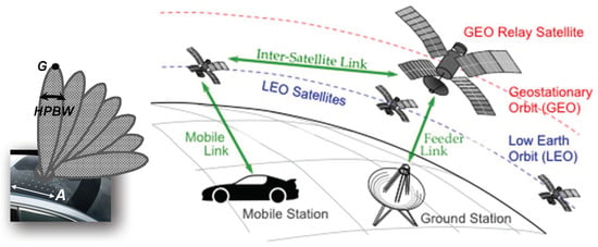
Figure 1.
Satellite platform scenario of a low Earth orbit satellite constellation to communicate with mobiles, using a relay satellite in the geostationary orbit for an inter-satellite link.
Figure 2 (left) illustrates the 5G cellular network architecture with different cells (layers) [3,4]: (1) macro cells (coverage layer) with high mounted sector antennas to cover large areas for the use cases in all three usage scenarios according to Appendix A, i.e., enhanced/extreme Mobile BroadBand (eMBB), massive Machine-Type Communications (mMTC), and Ultra-Reliable and Low-Latency Communications (URLLC), usually with relative low capacity, (2) micro and pico cells (coverage and capacity layer) with small antennas often below rooftops for additional capacity and coverage also for use cases in all three usage scenarios, and (3) small pico and femto cells (super data layer) with Multiple Input Multiple Output (MIMO) antennas (see Figure 2 (right)), particularly for the use cases in usage scenario eMBB with very high data rates. To enable these high data rates, the operating frequency will be shifted into the mm-wave range, whereas the first two layers are operating in the sub-6 GHz range (see spectrum recourses in Appendix A).
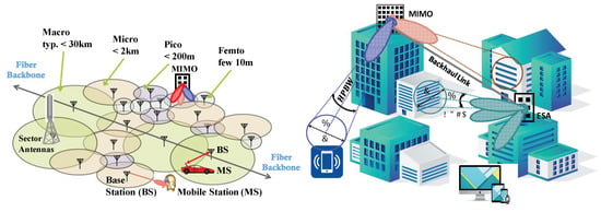
Figure 2.
5G network architecture (left). Coverage (footprint) of Electronically Steerable Antennas (ESAs) and multi-beam antennas at certain distance d, resulting in an area diameter of for small (right). HPBW: half-power beamwidth.
This evolution of wireless communications is primarily driven by an ever-growing demand for higher data rates in order to meet the needs for increasing the capacity per subscriber and the increasing number of subscribers (see Appendix A), i.e., to keep up with the remarkable speed-up of fiber optic networks. This demand on extremely high data rates and hence bandwidth leads inevitably to increasing operating frequencies of wireless communication and access systems up to the mm-wave range, where still large frequency resources are available. However, power link budget considerations in particular, which are dominated by the free-space propagation losses at these high frequencies (see Figure 3, left) require large (in terms of wavelength), highly directive, high-gain antennas to focus the narrow beam from a user terminal or mobile station toward the desired hub (satellite, access point, relay, or base station). Traditionally, this is done with a static beam formed, e.g., by a simple parabolic dish. The larger the antenna, the higher the gain, the narrower the beam for a certain frequency. This can be seen from Figure 3 (right) for an antenna example with quadratic aperture of size A = B versus frequency, e.g., a horn antenna or a microstrip patch array. The parameter is the gain G of the antenna and corresponding half-power beamwidth (HPBW). For a required gain with corresponding HPBW, the size of the antenna needed to assure the communication link strongly goes down with frequency, i.e., the number of radiating elements being apart in case of an array.
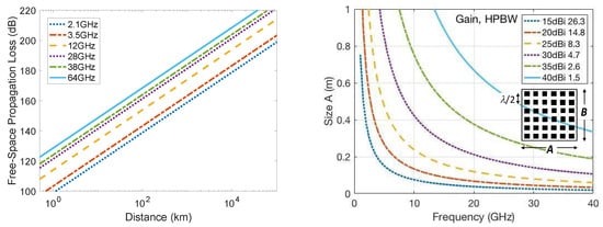
Figure 3.
(Left) Free-space propagation loss , where d is the distance between the communication partners, is the wavelength, is the speed of light, and is the operating frequency as a parameter for two 5G sub-6 GHz bands as well as some micro- and millimeter wave frequencies allocated for future 5G and satellite platforms (see Appendix A). (Right) Calculated gain and half-power beamwidth in degrees of a quadratic antenna array with size A = B and with radiating element distances of , assuming an aperture efficiency of and −10 dB-taper of the aperture field with k = 1.15.
However, when the hub or user terminal is moving, then these antennas have to be steered by heavy and bulky mechanical systems, which are impractical to deploy wide-scale applications. Therefore, smart antennas will be a major element in future to alter the narrow beam continuously toward the desired communication partner for a reliable link and for suppressing interference effectively as well as to increase the capabilities of wireless platforms, i.e., the overall capacity and spectrum efficiency. An example of an antenna with multiple beams covering different areas is illustrated in Figure 2 (right). This requires advanced antenna technologies such as analog, digital, or hybrid 3D-beam-steering/beam-forming, massive Multiple Input Multiple Output (MIMO) and network MIMO, where a significantly more advanced baseband computation and Radio Frequency (RF)- and antenna hardware is required to meet the complex requirements [3]. Implementing smart antenna concepts is very challenging at mm-waves, where complexity, technological constrains, and cost increase. At present, there are different approaches to enable cost-efficient, low-profile Electronically Steerable Antennas (ESAs), using different technologies to improve the performance while reducing the manufacturing cost to an economical price point [2].
Beyond smart antennas, reconfigurable hardware concepts and technologies for smart user devices and terminals as well as for the base stations and satellites are crucial for the deployment of the new platforms above, following to some extent the Software-Controlled Radio (SCR) or even the Cognitive Radio (CR) approaches, which would enable the user handset to look at the radio landscape in which it is located and choose the optimum radio access network, modulation scheme, and other parameters to configure itself to gain the best connection and optimum performance. Hence, to enable computationally intensive, adaptive air interfaces, programmable digital baseband and reconfigurable analog RF-frontend components such as tunable filter, phase shifters, and adaptive matching networks require control by software [2]. Figure 4 illustrates various applications and platforms with some important characteristics. In particular for mm-wave systems, the bottleneck of this approach is the reconfigurable/tunable components in the analog Radio Frequency (RF) frontends of the transceiver hardware and the antennas, to provide smart system functionalities, i.e., to dynamically change/tune the characteristics of these components electronically (instead mechanically) to enable (1) adaptive impedance and power matching, (2) dynamic frequency tuning (center frequency and bandwidth), (3) polarization tuning and converting, (4) electronically reconfigurable multi-beams as well as electronically beam-steering and beam-forming of single or multi-beams [2].
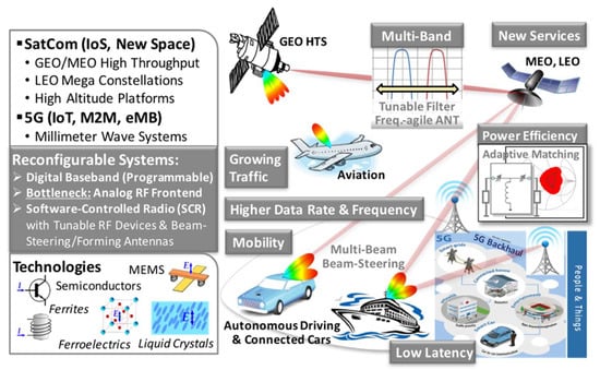
Figure 4.
Scenario of various applications and platforms with some important characteristics, including beam-steering antennas and agile components, following the software-controlled radio approach. Reprinted from [2], Cambridge University Press, 2020.
These reconfigurable/tunable components such as RF switches, varactors, adaptive matching networks and filters, frequency-agile antennas, frequency-selective surfaces, polarization-agile antennas and polarizer, discrete, and continuous phase shifters, and based on it, beam-steering antennas can be realized with different materials and technologies, which are symbolized in Figure 4 at the lower left:
- ▪
- in semiconductor technologies [5,6,7,8,9,10], in particular silicon technologies (Complementary Metal-Oxide-Semiconductor (CMOS) and Bipolar CMOS) that offer much lower cost as compared to Indium Phosphide (InP) or Gallium Arsenide (GaAs) technologies, and can address consumer applications,
- ▪
- with RF MicroElectroMechanical Systems (RF-MEMS) [11,12,13,14,15,16,17,18,19,20,21,22,23,24,25], and
- ▪
- by using functional materials such as ferrites [26,27,28], ferroelectrics, mainly Barium Strontium Titanate (BST) capacitors, filters, and phase shifters in thin or thick-film technology [29,30,31,32,33,34,35,36,37,38,39,40,41,42,43,44] and the Microwave Liquid Crystal (MLC) technology beyond optics.
With the emergence and progress of newly developed LC mixtures specifically synthesized for microwaves since 2002 [45,46,47,48,49,50,51,52,53,54,55,56,57,58,59,60], innovative concepts and designs with appropriate biasing schemes enabled numerous high-performance MLC components and devices in the RF domain, which fully exploit the microwave LC’s unique properties: various planar delay line, metallic and dielectric waveguide phase shifters at different frequencies [45,46,47,61,62,63,64,65,66,67,68,69,70,71,72,73,74,75,76,77,78,79,80,81,82,83,84], tunable resonators and filters [85,86,87,88,89,90,91,92,93,94,95,96,97,98,99], tunable power dividers and RF switches [80,99,100,101,102,103,104], tunable metamaterial structures, frequency-selective and high-impedance surfaces [105,106,107,108,109,110,111,112,113,114,115,116,117,118,119,120,121], and electronically steerable or reconfigurable antennas, which might be further subdivided into frequency-agile antennas [122,123,124,125,126,127,128], polarizer and polarization-agile antennas [129,130,131,132,133], deflecting gratings and lens antennas [134,135,136,137,138,139,140], mixed beam-switching and beam-steering antennas [141,142,143], beam-steering reflectarrays [144,145,146,147,148,149,150,151,152,153,154,155,156,157], leaky-wave antennas [158,159,160,161,162,163,164], and beam-steering phased array antennas [68,76,101,128,141,165,166,167,168,169,170,171,172,173,174,175,176,177,178,179]. These MLC components are discussed in some detail in [2].
In contrast to traditional microwave reconfigurable components with PIN diodes, Field-Effect Transistor (FET), RF-MEMS, ferrite switches or Monolithic Microwave Integrated Circuits (MMICs), MLC, and ferroelectric components provide continuous tuning with extremely low power consumption (quasi powerless), but with different response times. Compared to MLC components with response times from milliseconds to several tens of seconds (depends on the line topology and biasing scheme), ferroelectric ones can be tuned extremely fast in the nanosecond range; however, these are accompanied with much higher dielectric losses above 10 GHz than MLC components.
A first review of the potential of the MLC technology was given in [180] and more specifically in [181], including material properties and characterization as well as some exemplary examples of MLC components. A very comprehensive overview on and a comparative review of available microwave LC materials as well as techniques employed for their characterization and their key application-relevant properties by incorporating a great number of publications and their results in this specific field is presented in [182]. An even more comprehensive overview over the MLC technology with particular details is given in chapter 5 of the book [2], including fundamentals such as the electromagnetic properties of liquid crystal materials, the elastic continuum theory, orientation mechanisms, biasing schemes, dedicated wideband and narrowband characterization techniques over a wide frequency range from few GHz to few THz, concepts, and various approaches to enable numerous MLC components given above.
The objective of this paper is to review the fundamentals and progress of the MLC technology, dedicated to the deployment of MLC phase shifters and passive phased arrays (a specific type of ESAs), starting from well-known toward innovative concepts with the newest results. Therefore, the next section focuses on the performance metric of microwave Liquid Crystals (LCs), the orientation mechanisms, the biasing schemes, and the perspective of next generation microwave LCs and their deployment. Section 3 describes first the concept of passive phased arrays, and then the development of wideband, high-performance metallic waveguide phase shifters, only partially filled with LC, which are embedded into a waveguide horn array for a relay satellite in geostationary orbit. Then, continuously tunable subwavelength fiber, also partially filled with LC and integrated into a fully dielectric 1 × 4 rod antenna array, is briefly summarized at the end of this section. Both metallic and dielectric phase shifters require high-bias voltages for tuning, accompanied with slow response times in tens of seconds due to large LC layer heights; however, these are sufficient for some specific applications. Finally, Section 4 focuses first on well-known planar inverted microstrip line and grounded CPW phase shifters, then, introducing innovative concepts for flat passive beam-steering phased array antennas, comprising LC-tunable phase shifter stacks with thin LC varactors for fast tuning in the range of 30 ms for 400° phase shift. These stacks are fabricated in a Liquid Crystal Display (LCD) process in partnership with a display manufacturing company for producing and commercializing cost-efficient large-scale ESAs that are well suited for satellite ground and user terminals, but also for 5G mm-wave systems.
2. Microwave Liquid Crystal Technology
In the last two decades, novel nematic LC mixtures have been specifically synthesized for microwaves. These anisotropic microwave Liquid Crystals (LCs) feature tunability in relative permittivity of about 25–30% with low dielectric losses in the range of tanδ ≈ 10−2 to 10−3 above 10 GHz, decreasing slightly with frequency, which is different to all other materials above. Moreover, several radiation tests of these novel nematic LC mixtures for space qualification, including a total dose test, indicated no influence of radiation to microwave LCs [92,165,183]. Hence, they are also feasible for space applications. Moreover, these MLC components exhibit low frequency dispersion and extremely linear operation [184,185,186], i.e., very high power-handling capability. However, in contrast to traditional reconfigurable microwave components made of semiconductor materials, RF-MEMS, or ferroelectrics, MLC components might face some difficulties. (1) Due to their anisotropic nature, the orientation of LC molecules controlled by means of an electrostatic field might cause critical response times and might require complex biasing electrode networks. (2) Since LC is a fluid, it has to be infiltrated after processing via very small filling holes into some encapsulated packages such as flat panels for phased and reflect arrays or into long closed/sealed channels with respect to the wavelengths as for delay lines or into small cavities as for filters. This might complicate the preparation of the MLC components, but not necessarily when standard processes can be established such as the multi-layer low-temperature co-fired ceramic (LTCC) [167,187] or the Liquid Crystal Display (LCD) technology [188]. During the experimental phase, it might be even beneficial, since the LC already being filled into a component can be exchanged by another one later for improvement or comparison. So far, it allows flexible handling. Thus, MLC technology definitely enables a low-cost, robust, and reliable mm-wave hardware solution for the large-scale manufacturing of compact and flat reconfigurable/tunable RF components, when standard processes such as LTCC or LCD technology can be applied for fabrication.
2.1. Performance Metric of Microwave Liquid Crystals
Liquid Crystals (LCs) are dielectric materials with highly anisotropic characteristics, which can be grouped into three different mesophases between solid/crystalline and liquid/isotropic states according to Figure 5. These mesophases can be separated by orientation and positional order into nematic, smetic, and cholesteric [189,190,191,192]. The nematic phase is the most commonly used phase of LCs at microwaves between the melting point Tm and clearing point Tc. Within this nematic phase, the orientation of the rod-shaped molecules, which includes a polar group that produces a dipole moment, can be changed by an external electrostatic field. This results in a highly anisotropic permittivity tensor. At the macroscopic scale, the time-averaged direction of the molecules’ long axis is denoted by a director , where the permittivity tensor reduces to the one according to Figure 6, due to the molecule’s rotational symmetry. Some properties of LCs and the elastic continuum theory are given in many books and publications, e.g., in [2,189,190,191,192,193,194,195,196,197,198,199].
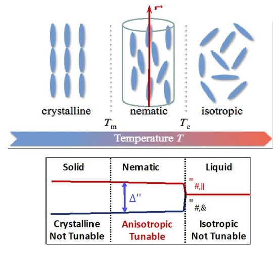
Figure 5.
Schematic of a nematic liquid crystal material depending on the temperature, exhibiting a perfect alignment with the order parameter S = 1 in crystalline solid state (left), indicating time- and space average directions of the molecules (for a Liquid Crystal (LC) unit volume element characterized by the director ) with order parameter 0 < S < 1 in the nematic phase (middle) and no molecular ordering with the order parameter S = 0 in liquid state (right).
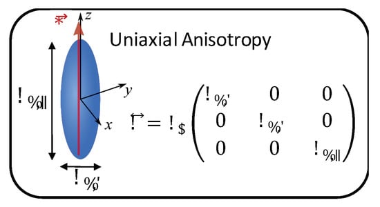
Figure 6.
Director parallel to the molecular long axis for a LC unit volume element and permittivity tensor.
In recent years, there have been many comprehensive studies of various high birefringence LCs, on their mesogenic and physical–chemical properties such as viscosity, birefringence, permittivity, anisotropy, and elastic constants, discussing the question of how to obtain LCs with a broad range of nematic phases. A comprehensive review of LCs dedicated for microwave application is given in [55]. In [48], dielectric properties of LC isothiocyanato–tolane derivatives with fluorine atoms at various lateral positions are analyzed from 1 kHz to 3 GHz. From the same group, a composition of large birefringence nematic LC, a eutectic mixture of isothiocyanato–tolane molecules are characterized from 26 to 40 GHz in a coplanar waveguide with an active part made of a central cavity with length = 3 cm and height = 100 µm similar to a rectangular waveguide to determine the dielectric properties and compare them with the standard display LC K15 (5CB, cyanobiphenyl) [49].
In [50,51,53,54], systematic investigations were focused on how the dielectric anisotropy in the low frequency region up to 1 GHz and the birefringence of the nematic LC phase at an optical wavelength (589 nm) influences the performance of LC mixtures at microwave frequencies. For this, the authors prepared a wide range of mixtures being nematic at room temperature and containing different classes of promising compounds. Their quasi-static and frequency-dependent dielectric properties, their birefringence, and the impact of those properties on their microwave behavior were analyzed by using the cavity perturbation method in [200,201]. As the measuring setup, several rectangular waveguide resonator cavities are designed for a TE102-mode at 9, 30, and 38 GHz with small holes to insert empty and LC-filled PolyTetraFluoroEthylene (PTFE) tubes, respectively. Measurements were carried out over a temperature range from −25 °C to 135 °C. External magnets were used to orient the LC molecules parallel and perpendicular to the RF field. Similar resonator measurements for the precise small-band characterization of LCs were also carried out in [202,203,204,205,206,207,208], whereas wideband measurements were presented in [46,209,210,211,212] by using specifically temperature-controlled coaxial-transmission line setups, and in [77,213,214,215,216] by using some other line or capacitance characterization setups. Beyond these measurements in the micro- and mm-wave range, low-loss LCs were also characterized and analyzed at THz frequencies from 0.1 to 0.35 THz with a free-space CW THz system in [217] and with a THz time-domain spectroscopy setup from 0.15 to 1 THz in [218], from 0.2 to 2.5 THz in [219], and 0.3 to 1.5 THz in [220], and soon later, from 0.3 to 8 THz in [75].
The MLC technology at TU Darmstadt was established by the first author in 2002 in close collaboration with the Performance Materials Division of Merck KGaA, Darmstadt. Since then, Merck synthesized and provided novel nematic LC mixtures with the highest material’s figure-of-merit, which were characterized over a wide frequency range from few GHz up to 8 THz. Beyond the lab-scale characterization setups above, a stable temperature-controlled LC-characterization system sketched in Figure 7 was built up, to measure the complex permittivity of new LCs at 19 and 30 GHz directly in Merck’s laboratory with very high accuracy and perfect reproducibility [56,58,59]. This industrial-scale setup is presented in particular detail in [2,74,75,208]. The design is based on the cavity perturbation method in [200,201] with several improvements to extract the complex permittivity tensor by formulating the Maxwell equations as an eigen-susceptibility problem of the considered sample [221,222] and by applying the variational approach to a triple-mode perturbation method [204]. This offers a direct solution of the desired material parameters by utilizing adequate and well-proven numerical techniques such as the Finite Element Method (FEM). The unloaded Q of the cylindrical aluminum cavity, containing a small amount of LC in a quartz tube, is better than 4200, enabling detecting very low dielectric loss of LCs in a test. The LC orientation is controlled by means of a static magnetic field of 0.35 T, which is generated by permanent magnets. Very recently, measurements are extended to 60 GHz [223].
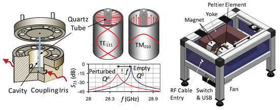
Figure 7.
Resonator cavity with coupling iris, where the empty or LC-filled quartz tube is placed in the center (left). A dual-mode resonator is shown for both TE111 and TM010 mode to measure the LC characteristics parallel and perpendicular to the Radio Frequency (RF) field in a single step only (middle), where an example of S21 measurements for empty and filled tubes is illustrated below. An industrial-scale temperature-controlled LC-characterization setup with permanent magnets (right).
Table 1 resume the elastic and electromagnetic properties of a few selected nematic LC mixtures at 19 GHz and at room temperature, except for MDA-03-2838 and MDA-03-2844, which are characterized at 9 GHz. In addition, three well-known LCs from optics are included: K15 (5CB) as a benchmark as well as E7 and BL006, since they have been widely used in many studies also for microwave applications. From literature to literature, the values of the parameters in Table 1 might slightly vary, generally due to measurement errors, but also because of different characterization techniques and equipment being used as well as different environmental factors such as humidity and temperature.

Table 1.
Dielectric and elastic properties of different LC mixtures at room temperature. The values for , , and are constants for splay, twist, and bend deformations according to [191,192,195], is the rotational viscosity, the anisotropy at low frequency, typically at 1 kHz, and and are the material’s tunability and figure-of-merit, respectively. Microwave parameters are measured at 19 GHz, except for MDA-03-2838 and MDA-03-2844, which are characterized at 9 GHz.
The results of many more LC mixtures at different frequencies are summarized in [182]. In general, all microwave LCs offer low dielectric constants in both principal directions, typically in the range of 2.4 to 2.6 for perpendicular orientation and 2.9 and 3.5 for parallel orientation of the director , thus satisfying low permittivity requirements. Loss tangents are typically tanδ ≤ 0.015. The following performance parameters are directly derived from the measured electromagnetic quantities, the anisotropy and tunability in relative permittivity, as well as the material’s figure-of-merit:
Compared to standard display mixtures K15, E7, and BL006, Merck’s first-generation LC compounds such as the GT3 series, having a long conjugation body with biphenyl or terphenyl structure, exhibit already much higher anisotropy, tunability, and figure-of-merit of the materials. This has even been improved by Merck’s second-generation LC mixtures such as the GT5 series and TUD-566, which use single classes, including bistolane and other novel components with triple bonding in between. With these LC’s, tunability is more than doubled and the material’s figure-of-merit is increased by factor 9 to 13 compared to standard LC K15, where to the author’s knowledge, of 46 to 64 are the highest values reported so far at microwaves. However, the tuning speed or response time are much slower than for K15 and the first-generation LCs, as can be seen from Figure 8.
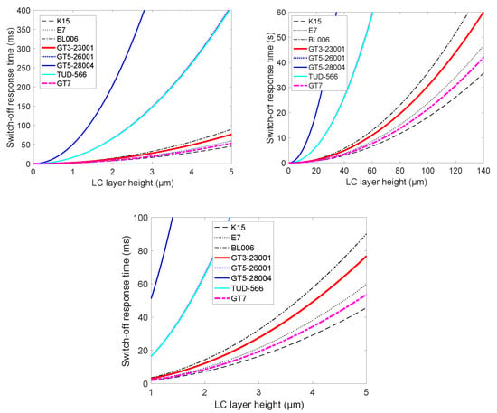
Figure 8.
Switch-off response time of a parallel-plate capacitor cell filled with LCs from Table 1 versus the LC layer height up to 5 µm (left) and up to 140 µm (right). The curves for TUD-566 and GT5-26001 are nearly identical. The lower plot is a zoom out.
2.2. Orientation Mechanisms and Biasing Schemes
Actually, the response time is the most critical parameter for tunable LC components, which is defined as the time interval required to reach an equilibrium state of LC devices [74,143,175,185,189,191,192,196,199]. This will be explained for an LC-filled parallel-plate capacitor according to Figure 9a, using the basic or hybrid biasing scheme, which is known from LCDs.
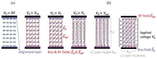
Figure 9.
(a) Basic or hybrid biasing scheme of a parallel-plate capacitor filled with LC of a layer height hLC. An alignment layer on the plates is assumed to pre-align the LC molecules initially in parallel to the surface (left). When bias voltage > is applied on the plates of the capacitor, the tube-like LC directors start to change its orientation from the initial state slowly toward the field lines of the electrostatic bias field (three pictures in the middle). For Vb = Vsat, LC directors are almost in parallel to the field (picture 5 from the left). (b) Fully or all-electrical biasing scheme for a parallel-plate capacitor without any pre-alignment layer by introducing a second pair of electrode, orthogonal to the plates of the capacitor cell.
To make use of the LC’s anisotropic nature, the orientation of the LC molecules must be controlled by means of electrostatic fields between the two plates (pair of electrodes) of the capacitor. Similar to LCDs, additional alignment layers are used, e.g., they are made of a spin-coated, cured polyimide film such as Nylon 6, having a thickness typically in between 50 and 100 nm, which is mechanically rubbed with a velvet cloth [185]. The result of this rubbing is a microscopic grooving of the polyimide surface, which anchors the LC molecules in the vicinity of this thin layer along the rubbing direction in parallel to the surface, according to Figure 10.
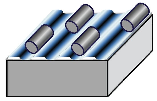
Figure 10.
Schematic of the pre-alignment layer (blue), which anchors the LC molecules in the direction of the grooves being rubbed into the polyimide film with a velvet cloth.
Accompanied with the tendency of LC molecules to align in parallel to each other, this concept can be principally used for pre-orientation of the LC molecules in a preferred direction. This pre-alignment layer is particularly useful in thin planar structures with LC layer heights hLC < 150 µm, since with higher layers, more LC molecules are no longer in parallel to the surface, because of decreasing anchoring forces, reducing the orientation effectiveness. The effect of alignment layers—their thickness, orientation, and deepness of the grooves—on an LC device’s tuning effectivity is analyzed in [2,74,175,185,224].
When a bias voltage Vb (AC typically at 1 kHz) is applied on the plates of the capacitor in Figure 9a, exceeding a certain threshold voltage > , the LC directors start to change their orientation from the initial state parallel to the grooves of the alignment layers toward the field lines of the electrostatic bias field . This threshold phenomenon is well-known as a Fréedericksz transition [185,191,192,199], which defines the voltage where the electric and elastic forces of the surface anchoring are in an equilibrium. In thin planar structures, the splay deformation is dominant, resulting in a threshold voltage of
Hence, it is proportional to the square root of the elastic constant for the splay deformation over the anisotropy at the biasing frequency. It differs for the various LC mixtures of Table 1, which are typically around 1 V. With > , the electric torques are exceeding the elastic ones, and the orientation of most LC directors starts to align more and more toward the orientation of the field lines of (see the three pictures in the middle of Figure 9a), until nearly all LC directors are oriented along the field lines for = Vsat. Beyond this saturation state > , no change in permittivity can be observed anymore.
When a RF field RF is applied at the parallel plate capacitor, it will experience different relative permittivities ε, and of course, different dielectric losses tanδ, depending on the changing orientation of the LC directors with respect to the fixed orientation of the RF field vector RF, which is vertical polarized as the tuning field in Figure 9a, since both are not decoupled. Initially, when no bias voltage is applied between both plates, the LC directors are oriented in parallel to the surfaces, i.e., by default, they are perpendicularly aligned to the RF field RF. Hence, the RF field experiences a relative permittivity of and loss tangent tanδ⊥. With increasing biasing voltage, LC directors starts to align more and more toward the orientation of the field lines of , i.e., in parallel to . Hence, experiences a material’s effective relative permittivity, which varies from continuously toward , which is accompanied by a change in the loss tangent from tanδ⊥; toward (see also Figure 16 for a tunable inverted microstrip line). Thus, varying by changing the orientation of LC directors due to the bias field , the capacitance of the parallel plate capacitor can be tuned, building up a tunable LC varactor.
The time it takes to change from to by applying a fast voltage source from Vb = 0 V to Vb > Vsat is the rise or switch-on response time.
When the bias voltage is released, the LC directors (in parallel to RF) are going back to the initial state in parallel to the alignment layers (perpendicular to RF) by means of the surface anchoring forces. Hence, the time it takes to change from to is the decay or switch-off response time.
The switch-on response time according to Equation (5) is always much faster by than the switch-off response time according to Equation (6), since it is driven by the voltage Vb < Vsat, which is much stronger than the low anchoring forces to reorient the LC molecules back into the initial state after releasing the voltage. Therefore, the switch-off response time is the most critical parameter for tunable LC devices. It is plotted in Figure 8 for most LCs in Table 1 versus the effective LC layer height hLC, where it is getting obvious that the simple hybrid biasing concept is only feasible for low profile (thin, flat), planar structures with hLC ≤ 5 µm to achieve switch-off response times for some LCs, and at the same time, control voltages Vb < 10 V. With increasing effective LC layer height hLC, the control voltage will increase up to a few tens of volts, and particularly, the switch-off response time will increase, e.g., up to about 30 s for hLC ≈ 100 µm, which might be still feasible for portable applications, just to reconfigure the characteristics such as the antenna beam or for slow-moving applications such as for a relay GEO satellite to track LEO satellites, but this will be impractical for on-the-move applications, e.g., to track the signal from a satellite by a moving car, ship, train, or airplane. Hence, the effective LC layer thickness hLC is a decisive design parameter to reduce the control voltage and the switch-off response time. However, the decreasing LC layer thickness is limited in planar line topologies, because of the increasing metallic losses and 50 Ω impedance mismatch; e.g., a typical 50 Ω design of a microstrip delay line (see Section 4.1) would be of an effective LC layer height of 60 to 100 µm and a width of the signal electrode of 100 to 200 µm to avoid increasing metallic losses, which exceeds the dielectric one [74]. Hence, high performances combined with fast switch-off response times is not possible to achieve at the same time for standard planar line topologies. Here, innovative concepts are required to overcome these problems. A promising solution is the loaded-line concept, where lines are periodically loaded by very thin, fast-tuned LC varactors with < 5 µm [175,185,225,226,227,228]. Figure 11 exhibits the side view of such a LC varactor, presenting two capacitors in series. Floating top and bottom electrodes are processed on 700 µm thick fused silica substrate, respectively. After applying a polyimide film to both substrates to pre-align the LC molecules, they are glued together. Two such varactors with different geometry, both filled with GT3-23001, had been realized and characterized in [225,226]:

Figure 11.
Schematic of an LC varactor with a floating top electrode and bottom electrodes, forming the two plates of the capacitor with distance hLC, where later LC is filled in.
- ➢
- Var1 with w = 1000 µm, ℓ = 450 µm, hLC ≈ 5 µm, C = 0.95 pF, fR = 7 GHz, = 22 ms, = 92 ms and
- ➢
- Var2 with w = 300 µm, ℓ = 225 µm, hLC ≈ 1 µm, C = 0.8 pF, fR = 7.5 GHz, = 1 ms, = 4 ms,
where the response times measured for of about 1 µm and 5 µm, respectively, clearly follow the square law. Taking into account some uncertainty in the determination of the exact rotational viscosity , elastic constant , and in particular, LC layer height , the values for above agree well with the one from Equation (6) of 3.2 ms and 80 ms for a thin LC capacitor of 1 µm and 5 µm height for GT3.
Beyond hLC > 100 µm, the hybrid biasing concept is not feasible at all, not only because of the dramatic increase in response times, but also because tunability decreases with increasing hLC, since more and more LC molecules are not perfectly pre-aligned in parallel to the surface due to lower anchoring forces. Hence, for bulky or “thick” voluminous metallic or dielectric waveguide-based components with LC layer heights of several hundred of µm or even of few mm, only a fully- or all-electrical biasing scheme is sensible, using multiple pairs of electrodes without any pre-alignment layer. For the LC-filled capacitor, it would be by introducing a second pair of electrodes (e.g., made of very thin Indium–Tin–Oxide (ITO) material), orthogonal to the parallel plates of the capacitor in Figure 9b. In this case, a voltage is applied on the second pair of electrodes after releasing the voltage on the first one, forcing the re-orientation of the LC molecules toward the perpendicular direction to RF. This reduces the switch-off response time to change from to significantly, since it is now driven by according to Equation (5) for and not by the weak alignment layer forces, taking into account the horizontal effective LC layer thickness hLC in Figure 9b. Moreover, the voltage-driven response time can be further accelerated by overshooting with higher applied voltages for a very short time [74].
2.3. Software Design Tool for MLC Devices
A major objective in designing MLC components/devices is to maximize the material’s tunability, i.e., to achieve a high tuning effectivity , where is the orientation effectivity of a device in the unbiased state and is the orientation effectivity in the fully biased state beyond saturation > . Hence, describes quantitatively how much of the material’s tunability can be utilized by a proposed device layout, e.g., to optimize the tuning capacitance range of a specific LC varactor or to maximize the differential phase shift of a certain phase shifter topology.
E.g., for the capacitor in Figure 9a, where only pre-alignment by means of surface anchoring is active, the optimum = 0 would be achieved when all LC molecules are perpendicular to the RF field lines, whereas not all LC molecules can be tuned in parallel to the RF field for fully biasing with > , leading to an orientation effectivity < 1, and thus to a tuning effectivity < 1. Hence, for the design and investigation generally of arbitrary microwave structures, including LC-based varactors, phase shifters, filters, polarizers, etc., an in-house software tool “SimLCwg” has been implemented at TU Darmstadt [74,229,230], combining
- the finite difference method for static fields to simulate the director dynamics and
- the finite difference frequency domain method for a full RF wave simulation.
The flow chart of this software tool is given in Figure 12.
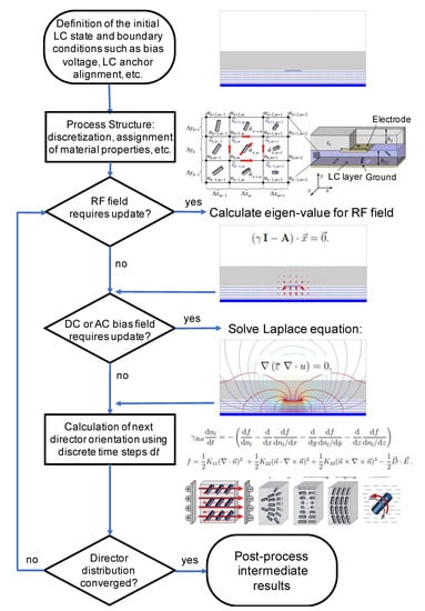
Figure 12.
Flow chart of the in-house software tool “SimLCwg”, combining the finite difference method for static fields to simulate the director dynamics and the finite difference frequency domain method for a full RF wave simulation [74,229,230].
It allows a physical insight and systematic analysis of MLC-based structures in dependence of the LC’s properties, the alignment layers, and their orientation, as well as the design parameters, e.g., in terms of the tuning effectivity and how to improve it, in terms of orientation effectivity over time and its response times and [74,175,231,232].
2.4. Next Generation of Microwave Liquid Crystals for Electronically Steerable Antennas
Beside the strong dependents of the response times on the effective LC layer height hLC, i.e., on the chosen device’s topology and biasing concept, it also depends very much on the elastic properties (the rotational viscosity and the elastic constant for the splay deformation) of the material itself as obvious from Figure 8, since the switch-off response time for the various LCs differ significantly. E.g., for the LC capacitor cell with a height hLC of 1, 2, 4, 5 µm filled with Merck’s first and second-generation LCs, is 3.1, 12.3, 49.1, 76.7 and 16.4, 65.5, 261.9, 409.2 ms for GT3-23001 and TUD-566, respectively, compared to 1.8, 7.2, 29.2, 45.6 ms for the benchmark LC K15.
In general, Figure 8 implies relatively slow switch-off response times compared to a fast shift of the ion from and back to the lattice center of a 1 to 5 µm thick ferroelectric capacitor, which is at least in the ns range. However, this sloth of nematic LCs implies excellent linear behavior [184,185,186]. To enable faster relaxation of the LC molecules, special classes of LC materials have been investigated such as polymer-stabilized nematic LCs [72,233,234], porous PTFE membranes impregnated with LC [185,235,236], nematic LCs doped with nanoparticles [51,185,237,238,239,240], ferroelectric LCs [51,241,242], ferroelectric LC mixtures doped with carbon nanotubes [243], BaTiO3 nanoparticles suspended in a ferroelectric LC mixture [244] and dual-frequency LCs [51,62,186,245]. This can improve the response time by one up to two orders of magnitude compared to pure nematic LCs. E.g., the phase shift response time could be reduced from more than 1 s down to 33 ms for a microstrip line phase shifter with a 100 µm thick membrane impregnated LC layer [235] or from about 20 s down to less than 0.4 s in an ITO glass cell and from 80 s down to 2 s in a CoPlanar Waveguide (CPW)-type phase shifter by using a polymer-stabilized nematic LC [72]. However, this improvement in response time is usually at the expense of much higher dielectric losses or lower anisotropy. Moreover, it often requires larger driving voltages for components with the same thickness. Therefore, despite a slower response time, research on nematic LCs is going on, since there is still room for improvements in the performance metrics in terms of tunability, the material’s figure-of-merit, and response time, where the overall performance metric can be tailored to match the requirements of a specific application.
Thus, some groups are developing LC materials of the third generation, focusing on a high tunability class, still with low losses. Thus, the systematic investigations in [50,51,53,54] have been updated in [60] with newly developed LC compositions with large optical anisotropy and low melting point on the basis of synthesized quaterphenyl and quinquiphenyl LC compounds, containing lateral substituents. Some selected four-ring compounds have a low melting point of less than 70 °C and exhibit large anisotropy 1.12 to 1.34, which is accompanied by low maximum loss tangent 0.002 to 0.006 at 29 GHz. However, the elastic properties, and hence, the switch-off response times, are not given there.
Merck too, developed LC materials of the third generation [58,59]. These are subdivided into a low-loss material class and a high tunability class with a substantially improved tunability of more than 30%. An example is GT7-29001 in Table 1 with a high anisotropy = 1.07 and high tunability = 30.3%, but a moderate material’s figure-of-merit = 26.1; however, it does exhibit a fast response time = 2.1, 8.6, 34.3, 53.6 ms for hLC = 1, 2, 4, 5 µm height, respectively, similar to the standard LC K15 (see Figure 8). Beyond microwave properties, parameter improvements related to the usage of LC in a real product aim (1) to increase the temperature range, (2) to reduce the tuning voltage, and (3) to increase the switch-off response time [58,59].
- (1.)
- Important improvements have been made to the low-temperature stability of the third generation of mixture classes by lowering the crystallization temperature Tc down to below −20 °C and −30 °C, respectively.
- (2.)
- The dielectric anisotropy at low frequencies Δε1 kHz could be increased significantly to values of 10 to 20 and above, leading to much lower threshold voltages, and hence, lower tuning voltages.
- (3.)
- Response times are proportional to the rotational viscosity. This parameter has been decreased to around 0.3 Pa·s for the third-generation LCs compared to 2100 Pa·s for second-generation LC TUD-566, thus enabling considerable improvements in response time, as can be seen from Figure 8.
These improved performance metrics of the third-generation LC mixtures combined with the parallel progress in the processing, manufacturing, and assembly technology will bring MLC-based components and devices, in particular passive LC-based antenna technology, a step closer toward becoming a part of the ground and user terminals of future LEO/MEO-satellite constellations and hubs of 5G mm-wave systems. A comprehensive survey of commercial mm-wave phased array companies focused on SATCOM and 5G applications is given in [2,246,247].
Thus, Kymeta has demonstrated a flat LC-metamaterial surface antenna in a satellite communication setup [248,249,250,251], where a first lab-scale demonstrator was already presented in 2010 by Damm et al. [158]. ALCAN Systems also demonstrated recently a first flat passive beam-steering phased array antenna with an LC-tunable phase shifter stack [252,253,254,255,256]. Both antennas have been fabricated in a partnership with display manufacturing companies for producing and commercializing cost-efficient large-scale Electronically Steerable Antennas (ESAs). All of them aim for low-profile and light ESAs with a modular concept to be scaled to any requirement and a thickness of a few centimeters only. Moreover, all work on the form factor of their ESAs, for compact stand-alone terminals with aesthetic appearance and to integrate them smartly or nearly seamlessly into the structure or body of a carrier object such as into the skin of an airplane or into the rooftop of a vehicle.
3. Passive Phased Arrays with Integrated Metallic and Dielectric Waveguide Phase Shifters
Phased arrays are most common, where the first phased array transmission was originally shown in 1905 by Nobel laureate Karl Ferdinand Braun, who demonstrated enhanced transmission of radio waves in one direction. Figure 13 sketches an electronic steerable antenna array, receiving an arbitrary incident plane wave from a satellite, which leads to a time delay of from one radiating element to the next one, where d is the distance between adjacent radiating elements and is the speed of light. This results in a differential phase shift along the equally spaced array with respect to the first radiating element of , where N = 4 is the total number of elements in our example.
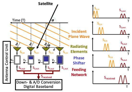
Figure 13.
Sketch of an Electronically Steerable Antenna (ESA) array, receiving an incoming plane wave from a satellite (left) and its signal inputs and outputs (right).
Therefore, the hardware implementation of Electronically Steerable Antennas (ESAs) in the analog domain requires by default tunable phase shifters with a differential phase shift of up to 360° beneath each radiating element of an array with a limited size of about λ0/2 × λ0/2 (λ0 is the wavelength in free space), and in addition, variable gain amplifiers when beam-forming is desired. By adjusting the right phase shift of each radiating element (large to low from right to left), all their small signals are summed up properly in the feeding network to a provide maximum signal.
This signal is being further proceed in the receiver (1) by frequency-down and analog-digital conversion, and (2) in the digital baseband. As a result of reciprocity, the same array can be used in the transmit mode, too. Then, the signal from the transmitter is first distributed equally by the feeding network to the phase shifter. By the proper electronic change of the relative phase of the small signal that each antenna element transmits, their overall contribution in the far field creates a larger focused beam in a particular direction. This beam can be directed instantaneously in any direction by fully electronic control, and hence, track the movement, e.g., of any satellite, no matter how or where you move, without the need for any mechanical moving parts. The gain and HPBW of an ESA are proportional and inversely proportional to the number of radiating elements.
A 16 × 16 horn antenna array is exemplary shown in Figure 14 for a relay satellite in geostationary orbit, which will be discussed in Section 3.2. It consists of circular horns and a three-dimensional feeding network in rectangular waveguide topology because of its intrinsically low loss. Beam-steering capability is achieved with a plug-in solution of a partially LC-filled waveguide phase shifter (see Section 3.1) between horns and the feeding network.
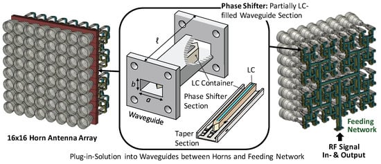
Figure 14.
Example of a 16 × 16 horn antenna array for a GEostationary Orbit (GEO) relay satellite. Beam-steering can be achieved by a plug-in solution of a partially LC-filled waveguide phase shifter (middle) between horns (left) and the feeding network (right). At both ends of the phase shifter section, there is a taper section to reduce reflections.
The key element of such phased arrays are the phase shifters, which can be realized in different line and waveguide topologies, and where tunability can be achieved by components in different technologies, as mentioned before. The focus here is on passive phase shifting by using the MLC technology only. As a measure for the performance of phase shifters, a figure-of-merit is defined by
where is the maximum differential phase shift and is the maximum insertion loss in all tuning states. The insertion losses depend on the topology, material, and operational frequency. The FoM in dependence on the voltage is [47,74,186]:
For the maximal tunability and by using the approximation for small , the maximal possible or optimal FoM is
where is the maximal loss factor of the LC and is the material’s figure-of-merit. This equation is only valid by presuming a constant dielectric loss of the LC for all tuning states, while all other materials are assumed to be loss-free. would be 113.5°/dB, 306.2°/dB, and 172.3°/dB for GT3, TUD-566, and GT7, respectively. In practice, the FoM is typically in the range of 60 to 80% of .
Voltage-controlled MLC-phase shifters are aimed for adjustments and flexible operation, i.e., to reconfigure their characteristics in operation. The requirements are generally a high FoM or high FoM per unit length, low power consumption to tune the device, and high power-handling capabilities with low intermodulation distortion. They can be built up in different topologies, including various tunable low-profile planar transmission delay lines as well as high-performance metallic and dielectric waveguides. While planar line topologies are inherently flat and compact, volumetric waveguide-based structures and devices are bulky, more complex and usually more expensive to implement. However, the electrical losses of metallic and dielectric waveguide structures, particularly at higher frequencies f > 30 GHz, are significantly lower than for corresponding planar structures. However, these bulky structures require complex biasing electrode configurations with higher biasing voltages than planar structures. Due to their trade-off properties between conventional planar and waveguide structures, Substrate Integrated Waveguide (SIW) structures have attracted many researchers in recent years.
3.1. High-Performance Metallic Waveguide Phase Shifter
Since metallic waveguides have intrinsically lower metal losses than planar transmission lines, they will provide higher FoM for the same LC, particularly with higher frequencies. This can be decisive for applications where limited power is available or where generally high effectivity is required by handling high power and where its bulky appearance is not critical as for the horn-antenna array in Figure 14.
The first experiments on an LC-tuned waveguide phase shifter at 30 GHz, using display LCs BL006 and E7, are presented in [257]. There, a center plane electrode, parallel to the broadside of a modified section of an WR28 rectangular waveguide applies a static field parallel to , and a pair of magnets on both small sides of the waveguide apply a static field perpendicular to , providing a phase shift of a bit more than 100° from 60 V to 200 V. The response times by the bias electric and magnetic fields was given as 0.1 s and typically 2 s, respectively.
An innovative approach in [64] made also use of a WR28 rectangular waveguide, but it was only partially filled with LC in a Teflon or Rexolite container, which was centered in the waveguide as shown in Figure 15 (middle), and by tuning the LC phase shifter section with multiple pairs of electrodes on the top and bottom wall of the waveguide according to Figure 15. It exhibits snapshots for the two extreme tuning states, where the simulation was carried out with the in-house software tool “SimLCwg” [74,229]. On the left, LC directors are mainly vertical oriented, i.e., in parallel to experiencing and (left), and on the right, LC directors are mainly horizontally oriented, i.e., in perpendicular to of the TE10 mode, which experiences and tanδ⊥. This purely voltage-driven biasing concept is necessary to achieve high tuning effectivity and reasonable response times, despite large LC layer heights hLC of several millimeters, since additional alignment layer forces have nearly no effect anymore. Large hLC values require also high bias voltages .
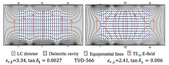
Figure 15.
Schematic of the director distribution in a partially LC-filled waveguide phase shifter for both extreme tuning states parallel (left) and perpendicular (right) to the RF field , using a configuration of three electrode pairs. The values below are given for the LC TUD-566. Reprinted from [2], Cambridge University Press, 2020.
To improve the performance, the phase shifter section is built up by an LC-filled container in the center, since the field strength of the TE10 fundamental mode is strongest there, providing high tuning effectivity. Since > , the RF field will be more concentrated in the center for LC orientation parallel to RF (Figure 15 left) than for LC orientation perpendicular to (Figure 15 right). At the same time, < tanδ⊥; thus, losses can be nearly equal in both tuning states by the right design, mainly the width of the container, which was chosen to be 1/7 of the width a of the waveguide. This has a positive impact in terms of lower average losses and higher differential phase shift, i.e., on higher FoM.
From measurements of a lab-scale demonstrator with a total length and a phase shifter section of 3 cm filled with LC TUD-566 in [64], the FoM was more than 200°/dB at frequencies around 35 GHz for magnetically biasing and drops down to about 140°/dB for electrical biasing, due to the losses of the biasing electrodes processed on a 12 µm thin Mylar foil and because the tuning effectivity could not fully be exploited as for magnetic biasing. To avoid reflections at the material edges, the LC container has a taper of 0.5 cm length at each side, while the metallic taper is integrated into the transition from the feed waveguide to the phase shifter section. For this lab-scale demonstrator [64], a voltage range of was chosen, resulting in an internal electric field of almost . The electrical biasing configuration uses five electrodes on each side, where parts of the electrodes has to be equipped with λ/4-stub lines and stepped impedance low-pass filters to suppress the coupling of the TE10 mode into stripline modes between the waveguide walls and the biasing electrodes. The waveguide itself was built up in a split-block design made of brass, in which the LC container is inserted. The split block has small gaps for the biasing electrodes to be lead out.
This concept has been also proved and demonstrated for W-band frequencies in [67,143]. The reflection is below −10 dB, the insertion loss is below −3 dB, and the differential phase shift is between 300° and 320°; hence, the FoM is in between 116°/dB and 148°/dB from 95 to 105 GHz for magnetic biasing only, nevertheless revealing the potential of this technology also for W-band applications. Electrical biasing with electrodes made of chromium and processed on a 20 µm thin PET film reacts very sensitively on the metal evaporation and photolithography process, causing microscopic cracks. These processing problems could not be solved sufficiently up to now.
3.2. Electronic Steerable Horn Antenna Array
For a relay satellite in geostationary orbit, establishing a link between moving low-Earth orbit satellites and a fixed ground station on Earth according to Figure 1, a light-weight Tx/Rx electronic beam-steering horn antenna array was aimed to design for down- and uplink in the frequency bands of 23 to 23.5 GHz and 27 to 27.5 GHz, respectively, within the project Lightweight InterSatellite Antenna-Electronical Steering (LISA-ES) funded by the German Aerospace Center (DLR) [75,76,176]. The desired scanning range is ±11°, aiming for a phase change rate of at least 5°/s to track the LEO satellite. For the final application, a 16 × 16 horn antenna array according to Figure 14, i.e., with 256 phase shifters for one polarization, is aimed to implement into the satellite. To achieve beam-steering capabilities, partially the LC-filled waveguide phase shifters sketched in Figure 14 aimed to plug into each branch of the rectangular waveguide feeding network for robustness, reliability, and long lifetime, to each horn of the array. All components are built up of micro-machined low loss, which was hard plastic (Rexolite 1422) electroplated with Ag/Cu for minimum weight. The materials used are space approved, including the LC [75,76,176].
The first experiments in the lab have been carried out with waveguide phase shifters in a split-block design made of brass [68,69]. To assure single-mode propagation in the LC-filled waveguide, smaller dimensions of and are used than those for regular waveguides in this frequency range. The design and measurement results with LC GT5-26001 over a frequency range from 21 to 35 GHz are given in [68,69]. Over the frequency range from 23 to 27.5 GHz, the matching is better than −12 dB. Only below 23 GHz does it go up to more than −10 dB. The IL is between −2 and −4.0 dB in this range, which was underestimated in the simulation, because waveguide losses could not be estimated precisely and the effects of the electrode sheets could not be taken into account in the simulations. The differential phase shift is above 450° for electrical biasing; hence, the FoM was about 120°/dB in the desired frequency range and 130°/dB in the frequency range of 27 to 32 GHz. The response times of this phase shifter were estimated to be between one and two minutes at room temperature. Since the phase shifter is designed for a temperature-controlled antenna at 60 °C, improvements in the order of magnitude of 10 to 12 is expected for the response time.
Based on these promising results, a light-weight 4 × 4 horn antenna array prototype with plug-in LC-based phase shifters is realized for individual measurements [75,76]. Each waveguide phase shifter with a length of 12 cm consists of an LC-filled Rexolite container, including the biasing electrodes, which is enclosed by a galvanically deposited silver-primed copper cladding of 0.5 mm thickness, and additional aluminum flanges with screws with a total weight of 12 g only. For biasing the LC-phase shifter, custom-built electronics provide up to 513 voltage channels. One provides a fixed voltage pair of ±164 V, while the other channels are tunable between ±164 V. In this way, each phase shifter can be individually tuned to a desired differential phase shift. The final outcome of various design iterations for environmental and RF-performance tests in [76] are as follows. In the frequency range from 23 to 27.5 GHz, reflection is below −13.7 to −18.7 dB in the lower band and below −11.1 to −11.7 dB in the upper band. The measured maximum differential phase shift is about 450° as predicted by simulations. However, the measured insertion loss varies between −4 and −6 dB in the frequency range above, and it is larger than expected from simulations. The minimum time for a 360° phase change is in between 16.1 and 138 s, while the maximum phase change rate reaches 5.1°/s to 45.4°/s, depending on the applied voltages. As a consequence, when losses could be reduced, the concept would become a viable option for the desired application [76].
3.3. Fully Dielectric Beam-Steering Rod-Antenna Array
Very recently, some investigations are also focused on an electrically tunable dielectric delay line phase shifter, inserting an LC section inside the dielectric core [78,80,82,83,100,177,181]. They offer low-loss propagation at very high frequencies and potentially low-cost fabrication by using processing technologies such as 3D printing, injection molding, or milling, since no metallic component is required for it. Thus, in [83], a continuously tunable subwavelength fiber, partially filled with LC G7 exhibits a FoM of about 130°/dB (with 22°/mm) in the frequency range from 85 to 110 GHz. Four of them had been integrated into a fully dielectric 1 × 4 rod antenna array, including the feeding network. Similar to a metallic waveguide phase shifter, dielectric ones require high voltages above 100 V (up to 200 V), and response times are slow. Thus, the switch-on response time is about 17 s, and the switch-off response time takes a few minutes. A summary of these new LC-tuned dielectric components such as filters, phase shifters, RF switches, multi-mode interference power divider networks, arrays, and lenses is given in [258].
4. Flat-Panel Beam-Steering Antennas with Low-Profile Phase Shifters with Fast Response
Among LC-based devices, the inverted microstrip line (IMSL) topology has been widely studied because of its relative high performance in the lower mm-wave bands. Moreover, particularly for ESAs, it enables low-profile phase shifters, which can be placed or integrated beneath any individual radiating element within an area of about λ0/2 × λ0/2. Even the length for a 360°-differential phase shift is more than λ0/2, this is feasible by spiraling/meandering or employing a specific feeding concept for a straight-line phase shifter or by miniaturization using, e.g., the slow-wave effect. In addition, it is possible to achieve high performances at mm-waves, combined with low response times, while reducing the manufacturing cost to an economical price point by using standard LCD processes. Its development toward the current state will be discussed in the following subsections.
4.1. Low-Profile Planar Inverted Microstrip Line and Grounded Coplanar Waveguide Phase Shifter
An early example of a 4 cm long inverted microstrip line (IMSL) delay line phase shifter filled with K15 can be found in [259]. It exhibits a FoM < 20°/dB for the X-band and a response time of about one second for a LC layer height of hLC = 50 µm and width of the strip line of w = 100 µm. A similar FoM < 20°/dB at 20 GHz was achieved in [260] by using a display LC BL-008 filled in an IMSL phase shifter on a glass substrate, yielding a phase shift of 370°, accompanied by an insertion loss of about 20 dB. The width of the strip line was w = 100 µm and the LC layer height hLC = 50 µm. In [261], two-phase shifter configurations have been studied, using inverted microstrip lines with two coplanar waveguide accesses, where the active parts are 3 cm and 1.1 cm long, respectively, and both are 100 µm thick filled with K15. The phase shift at 20 GHz was 61° with a bias voltage of up to 20 V, accompanied with an insertion loss roughly between 4 and 5 dB, i.e., an FoM in between 12°/dB and 15°/dB. With the emergence and progress of newly developed LC mixtures, the FoM could be improved significantly. Thus, with Merck’s first-generation LCs, an FoM of about 110°/dB at 24 GHz was already achieved in 2003 with an IMSL phase shifter [45,46,47]. Since then, various IMSL phase shifters at different frequencies are presented, e.g., in [65,70,74,77,128,166,173,174,175,185].
Figure 16 (left) illustrates its assembly: the strip or signal line (top) and ground plane (bottom) are processed on separated glass carrier substrates with . The inner sides of these carrier substrates with the strip line and ground plane, respectively, are covered by thin, rubbed polyimide films (thin blue lines in Figure 16 center) for pre-alignment of the LC director . Then, the substrate carrying the signal electrode is flip-chipped, introducing a cavity in between both substrates with a height hLC fixed by spacers. Then, this cavity is sealed to prevent a leakage of LC afterwards, when the LC is filled inside this cavity. This LC has a dielectric constant , which varies in between and , depending on the bias voltage Vb according to Figure 16 (right), where a few values of and for TUD-566 are indicated for different bias voltages. For electrical tuning, the strip line and the ground plane are used as biasing electrodes according to the hybrid biasing scheme, as explained before. With the change of due to the bias voltage V, the propagation constant changes, and hence, the differential phase shift for a certain physical length .

Figure 16.
Schematic of a tunable LC-filled inverted microstrip line (IMSL), using the hybrid biasing concept with polyimide films on top of the ground plane and strip line, both processed on a carrier substrate with εr,s (left). The cross-section illustrates its assembly: strip line (top) and ground plane (bottom) processed on glass carrier substrates with , each covered by thin, rubbed polyimide films (thin blue lines) for the unbiased state Vb = 0 V and a fully biased state Vb > Vsat (center). Permittivity and loss tangent versus bias voltage Vb (right). The values are given for the LC TUD-566.
A major objective in designing an IMSL phase shifter is to maximize the material’s tunability, to achieve a high tuning effectivity , and hence, a high differential phase shift and FoM. For example, if a carrier substrate with a significantly higher permittivity compared to the LC is chosen (), the RF field will propagate partially in this substrate instead in the LC section, reducing the tuning effectivity , and hence, the FoM. E.g., for = 2.2, 3.82, 7, and 10, the FoM is about 92, 87, 82, and 78°/dB at 30 GHz and 110, 106, 93, and 62°/dB at 100 GHz for an IMSL with = 200 µm, s = 100 µm and hs = 300 µm filled with GT3-23001 [74]. To compensate for the decreasing tuning effectivity, the length of a line phase shifter could be extended in practice to maintain the desired differential phase shift; however, this is at the expense of a larger size and higher insertion losses.
Another parameter that might affect the tuning effectivity is the rubbing direction of the polyimide film, since there are two different pre-orientations of the LC molecules possible: (1) along the cross-sectional plane and (2) along the propagation direction. This has been analyzed for an IMSL design with an effective LC layer height of and a width of the signal electrode of 200 µm to achieve a line impedance of 50 Ω [74]. Figure 17 shows the simulation results with the in-house software tool “SimLCwg” for the orientation effectivity of the IMSL filled with GT3 versus time in seconds after the switch-on and switch-off of the bias voltage for cross-sectional pre-orientation. The parameter is the biasing voltage from 1 to 15 V. To stress the switch-on and switch-off processes, there are logarithmically scaled curves specifically for , corresponding with the upper horizontal time axis.
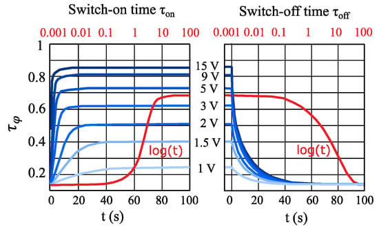
Figure 17.
Orientation effectivity versus time for and for the cross-sectional pre-orientation of an IMSL of hLC = 100 µm filled with GT3. The parameter is the biasing voltage from 1 to 15 V. In addition, there are logarithmically scaled curves for [74]. Reprinted from [2], Cambridge University Press, 2020.
In the unbiased state , where only pre-alignment by means of surface anchoring is active, not all LC molecules are perpendicular to the RF field lines, i.e., the orientation effectivity > 0, which is actually around 0.14. In the fully biased state beyond saturation ( > ), not all LC molecules are in parallel to the RF field, leading to an orientation effectivity < 1, which is actually 0.86 for 15 V. Thus, the tuning effectivity is for cross-sectional pre-orientation. For pre-orientation in the propagation direction, where only the short axis of the LC directors is effective for the RF field and the biasing field, is less, but = 0 is optimum, leading to a similar tuning effectivity . However, in this case, the tuning effectivity is equal to the orientation effectivity To sum up the results in Figure 17, the higher the bias voltage , the higher the orientation effectivity , having its maximum at the saturation voltage . Note that the response times approach theoretically infinite for each curve, i.e., for each bias voltage. Therefore, in practice, it is often defined as the 10 to 90% rise and the 90 to 10% decay in the orientation effectivity . While the rise time depends very much on the bias voltage, the decay time is nearly independent. Hence, and correspond to the switch-on and switch-off response times in Equations (5) and (6), respectively, and related to that, to the 10 to 90% rise and 90 to 10% decay in the measured capacitance for LC varactors or differential phase shift for LC phase shifters.
Beside the microwave LC properties, the performance of an MLC-based IMSL phase shifter depends strongly on its geometry and frequency. Plots to design an IMSL phase shifter are shown in Figure 18: filled with first-generation LC GT3-23001 (above), second-generation LC TUD-566 (middle) and third-generation LC GT7-29001 (below) at 30 GHz (left) and 60 GHz (right), respectively. These plots are calculated by using the in-house software tool “SimLCwg” according to the flow chart of Figure 12, which has been proven as an accurate simulation tool to predict the characteristics and dynamics of MLC-based structures and components over a wide frequency range in excellent agreement with microwave measurements in almost all of our investigations. These plots exhibit curves of the same phase shifter figure-of-merit (full red lines), line impedances ZLine (thin dotted gray lines), and orientation effectivity (dashed blue lines), which is equal to the tuning effectivity for pre-orientation of the LC in the propagation direction, as a function of the strip line width (vertical axis), thickness (lower horizontal axis), and the 90 to 10% decay time (upper horizontal axis), which corresponds to the switch-off response time and the decay in differential phase shift [74,230]. For a thin strip line of few µm only, the thickness between the substrate and the ground plane is about the effective LC layer height: . With these plots, LC-based IMSL phase shifters can be designed with desired performances before realization. As the top substrate, fused silica is chosen for simulation, assuming a height of hs = 300 µm, a relative permittivity of , and a dielectric loss factor of .
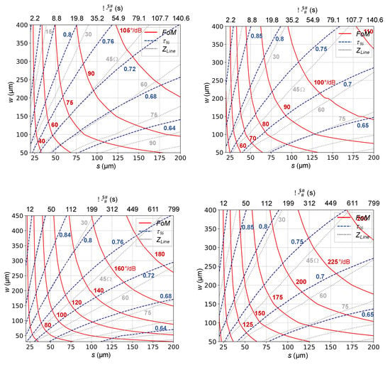
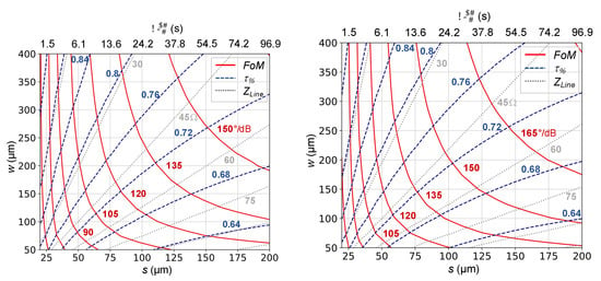
Figure 18.
Plots for designing an IMSL phase shifter filled with first-generation LC GT3-23001 (above), with second-generation LC TUD-566 (middle) and third-generation LC GT7-29001 (below) for 30 GHz (left) and 60 GHz (right), respectively. As the top substrate, use is made of fused silica with a height hs = 300 µm, a relative permittivity of , and a dielectric loss factor of . The electrical conductivity of the metal parts is set to . A pre-orientation of the LC in the propagation direction was chosen. These plots exhibit the curves of a constant phase shifter figure-of-merit () (full red lines), orientation effectivity (dashed blue lines), and line impedance Zline (dotted gray lines), depending on the strip line width (vertical axis), the thickness ≈ hLC (lower horizontal axis), and the 90 to 10% decay time , which corresponds to the switch-off response time (upper horizontal axis).
For a 50 Ω design, the IMSL phase shifter with an LC layer thickness of hLC = 100 µm requires a signal electrode of about w = 200 µm. At 30 GHz, the tuning and orientation effectivity is around ≈ 0.72 for GT3 and slightly higher for TUD-566 and GT7, due to the higher anisotropy. The reaches values of up to 90°/dB, 142°/dB, and 132°/dB for GT3, TUD-566, and GT7, respectively. The large difference in between TUD-566 and GT3 can be explained by the drastically reduced dielectric losses of TUD-566; however, this is at the expense of a much longer decay of 199 s compared to 35.2 s, which is due to the much larger ratio of rotational viscosity over the elastic constant, compared to 0.03. Similar for GT7, its dielectric loss is lower and its anisotropy is significantly larger than for GT3, resulting in a higher . However, in contrast to TUD-566, its ratio of rotational viscosity over the elastic constant is ; i.e., it is even lower than for GT3, resulting in a faster switch-off response time of 24.2 s. Hence, the third-generation LC has nearly the same FoM than the second-generation LC, but it has an 8.2 times faster switch-off response time. Nevertheless, the response time remains still the critical parameter of the LC-based line phase shifter. It can be dramatically reduced by a thinner LC layer thickness hLC, which is accompanied with a higher orientation effectivity , but at the same time, with steeply increasing impedance mismatch to 50 Ω and significantly decreasing FoM due to increasing electrical losses. For the same design parameter at 60 GHz, the FoM increases, while the response time remains the same. This is mainly because the electrical losses decrease (despite the -law), since electrically, the dimensions increase by a factor of 2, and in addition, dielectric losses due to the LCs slightly decrease. Hence, these topologies are well suited for higher frequencies.
Another planar topology often used in the literature for LC-tunable phase shifters are grounded CPWs [66,74,262,263], where the schematic is shown in Figure 19 together with the calculated parameter plots for GT3 at 30 GHz by using the in-house software tool “SimLCwg” again. Comparing it with Figure 18 (upper left) indicates that the orientation effectivity (dashed blue lines) and the phase shifter figure-of-merit (full red lines) are significantly less than for an IMSL. Therefore, IMSL is the preferred planar line topology.
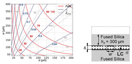
Figure 19.
Plots for designing a grounded CPW phase shifter filled with LC GT3-23001 for 30 GHz (right). As substrate, use is made of fused silica. The electrical conductivity of the metal parts is set to . These plots exhibit curves of constant phase shifter figure-of-merit (, full red lines), orientation effectivity (dashed blue lines), and line impedance (dotted gray lines), depending on the signal line width (vertical axis) and the thickness ≈ hLC (horizontal axis).
Beside this analysis, some lab-scale demonstrators have been implemented to investigate the feasibility. In [45,46,47,186], two inverted microstrip line-based phase shifters were realized with similar geometry, i.e., with a physical length of about 50 mm and LC layer heights of hLC = 230 µm and 254 µm, respectively, as well as a line width of w = 600 µm, using a polyimide film PI-2555. Both result in a FoM of 110°/dB at 24 GHz with a Merck’s first-generation LC, MDA-03-2838, having a material’s figure-of-merit ≈ 11.8. The phase shifters were tuned by a bias voltage of up to 40 V, where 90% of the maximal differential phase shift was achieved by less than 20 V. A schematic and the realized phase shifter are shown in Figure 20. As substrate material, TMM3 from Rogers Corp. was chosen, which has a permittivity of and a dielectric loss of . The ground electrode and the carrier substrate on the top side are separated by a spacer made of RT/Duroid5880 from Rogers Corp. with and , forming the LC cavity. Thin polyimide films of about 200 to 300 nm thickness was spin coated on both inner surfaces to pre-align the LC molecules.

Figure 20.
Realized broadband inverted microstrip line (IMSL) phase shifter for frequencies from 1.125 up to 35 GHz. Different parts (left) and assembled phase shifter with filling channels (right) [47,186].
For another IMSL phase shifter with a thinner LC layer height of hLC = 127 µm and line width of w = 300 µm for nearly 50 Ω design, using a polyimide film AL-3046, and two LCs, MDA-03-2838 and MDA-03-2844, the FoMs reduce to about 67°/dB and 75°/dB, respectively, because of increasing ohmic losses with decreasing electrode distances. However, for both, the FoM was nearly constant over a frequency range from 20 to 33 GHz. This time, fused silica was used instead of TMM3 [47,186]. Compared to GT3 with a FoM of around 100°/dB at 30 GHz according to Figure 18, it is less, due to the lower material’s figure-of-merit. At 30 GHz, the measured differential phase shift was 330° and 340°, which was accompanied with insertion losses of 5 and 4.5 dB for MDA-03-2838 and MDA-03-2844, respectively, while the reflection coefficient S11 was less than −10 dB over the whole frequency range [47,186]. The measured 90 to 10% decay time in the differential phase shift was in the range of roughly 30 to 50 seconds, which agrees well with the switch-off response times for GT3.
To assess the linearity of the phase shifter, first large-signal measurements at f0 = 7.4 GHz were carried out for an IMSL section of 6 cm length; however, seven times meandered. The LC layer height was hLC = 100 µm filled with the LC MDA-03-2844. The measured reflection coefficient was < −21.5 dB and the insertion losses were less than 3.3 dB, leading to a FoM = 40°/dB [184,185,186]. The setup used in [184] allows a resolution of IP3 measurements of at least 60 dBm at a total available power level of approximately 40 dBm to the device under test or P0 = 37 dBm per tone, respectively. Figure 21 shows the measured IP3 versus the frequency difference Δf of the two tones at room temperature and the maximum input power for three device configurations: empty (air), filled with K15, and MDA-03-2844. The noise floor generated by the sources is at −55 dBc in close proximity to the tone at 100 Hz and decreases to −80 dBc for distances Δf >10 kHz. Hence, the IP3 values for Δf < 1 kHz are only an estimate. For K15 with respect to air, a slightly increased IP3 for a small Δf is visible, whereas for MDA-03-2844, it is not visible. This is because the reorientation (response times) is much slower in reaction to an external stimulation such as the RF beat, despite higher anisotropy. Generally, the IP3 measurements exhibit excellent large signal characteristics, i.e., an extreme high linearity for the phase shifter device with both LCs.
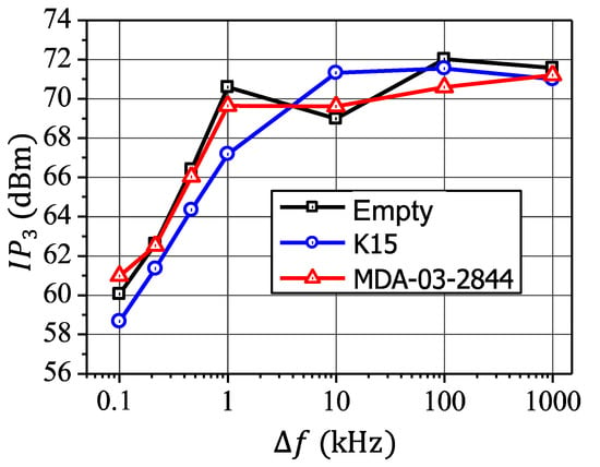
Figure 21.
Measured IP3 versus the frequency difference Δf of the two tones at room temperature and maximum input power for three device configurations: empty (air) and filled with K15 and MDA-03-2844 [184,185,186].
One way of realizing a reliable, hermetically sealed cavity for LC is by using the standard low-cost multi-layer low-temperature co-fired ceramic (LTCC) technology, which is space qualified. LTCC is mechanically stable and allows a three-dimensional structuring, using conductivity, resistance, or capacitive pastes between the layers. Structures on different layers can be connected by vias, and those vias can also be used to form metallic cavities inside the LTCC structure. By this, a cavity similar to a metallic waveguide can be built up inside the LTCC, thus combining high performance with low profile. After processing the LTCC structure, microwave LC mixtures are filled into these cavities, thus enabling compact and tunable components such as filters and phase shifters [27,97,103,165,166,167,183,264,265,266]. These phase shifters can easily be integrated into an LTCC module together with biasing lines and electronics for tuning as well as with individual antenna elements to form an array.
In [74], a LTCC delay line phase shifter based on an IMSL topology was investigated, using different LTCC CT707 layers with at 30 GHz. For a proof-of-concept and a comparison, the realized LTCC-IMSL phase shifter was filled with TUD-188 (having similar performance than GT3) and TUD-566. Matching is better than −13 dB over the frequency range from 25 to 35 GHz, while the insertion losses are below 3.5 dB and 4.5 dB, respectively. Measurements of the empty phase shifter indicated that the insertion losses are dominated by metallic losses, leaving, e.g., for TUD-566 a proportion of just around 1.3 dB. The maximum differential phase shift rises from about 220, 250° to around 300, 350° over the above frequency range, while the FoM keeps around 45, 70°/dB for TUD-188 and TUD-566. The measured switch-off response times are about 33 s and 150 s, respectively, which might be feasible for portable applications, just to reconfigure the antenna beam, or for slow-moving applications, but definitely not for on-the-move applications, requiring high beam-scanning rates. To speed up tuning, the LC layer height hLC has to be decreased significantly, but this means increasing insertion losses [74,175], i.e., a lower FoM, according to Figure 18. Hence, with the IMSL topology, high FoM and fast switch-off response times, i.e., fast beam-scanning rates, are not achievable at the same time.
4.2. Fast Tuning Low-Profile Planar Delay Line Phase Shifter
To overcome the response time limitations for on-the-move applications, innovative approaches and concepts are required for LC-based phase shifters. An early approach in [61] was introduced with a finline-based phase shifter. Using MDA-03-2838, and have been 0.09 s and 14.3 s compared to 0.035 s and 4.7 s for K15, respectively, measured at 40 GHz. However, these values are still too slow. Very promising line topologies for fast LC-tunable phase shifters are periodically loaded lines [74,175,228], e.g., slot lines or microstrip lines with periodically thin overlapping areas filled with LC, which builds up LC varactors, as sketched in Figure 22.
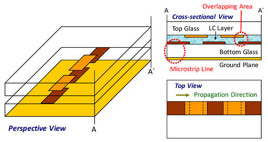
Figure 22.
Schematic of a serially loaded microstrip delay line with LC varactors, build up by an overlapping area of an interrupted microstrip line filled with LC.
A very promising approach involves coplanar waveguides loaded with periodically arranged, very thin LC varactors with heights µm [72,175,185,225,226,227,228]. This provides a significant reduction in switch-off response times down to less than 35 ms, when third-generation LC-filled varactors and a standard LCD process are used for production (see Section 4.3). A further advantage is the possibility of reducing the physical length of LC-based phase shifters due to the slow-wave effect of those structures. The schematic depiction of this concept is shown in Figure 23.
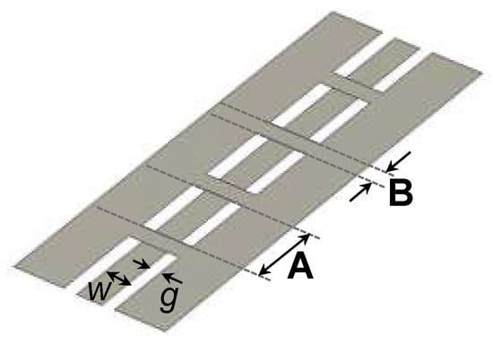
Figure 23.
Schematic of a CPW periodically loaded with LC varactors (bridges between ground planes), where the LC is filled in between the bridge (grounded plane) and signal line of the CPW.
For the design, the waveguide is split into alternating “pure” CPW segments A and capacitive loaded (grounded CPW) segments B, having different line impedances and . If those two segments are electrically short, the overall inductance of the loaded line is approximately ( and the capacitance corresponds to (. Therefore, the relation between the specific capacitance and inductance of a homogeneous line can be decoupled in favor of a higher tunability by preserving a desired input impedance of the loaded line at the same time. The complex propagation constant for the entire structure becomes:
It can be evaluated by using the aforementioned simulation tool, treating the dielectric and ohmic loss mechanisms in each of the line segments independently to calculate and for each tuning state, which results in four RF-eigenmode calculations for each section.
A detailed analysis and a proof-of-concept of such CPWs loaded with periodically arranged LC varactors along the line was first reported in [185,227,228]. The design schematic of a realized unit element is illustrated in Figure 24 (right), where the dark gray printed patch is a floating electrode of dimension (wV,1 × LV,1) processed on the top layer and biased by Indium–Tin–Oxide (ITO) strips of 10 µm width and 30 nm thickness (white colored). On the bottom layer, the CPW with width w and gap g is processed, where the center line widens to width wc along the length LV,1 beneath the floating electrode. The relatively large overlapping area of wc × LV,1, where the center line underlies the floating electrode form the parallel plates of the capacitor with a small height < 5 µm, being filled later with LC. Moreover, there are also ITO bias lines (gray) on the bottom layer, connecting the center line and the ground conductors, to assure that the center line is kept on the ground potential for DC or low AC bias voltages. After having processed the 1 µm thick gold structures (CPW and floating electrode) on both substrates by a standard lithography process, polyimide films are rubbed on both processed substrates in propagation direction with a thickness much lower than 100 nm to pre-orient the LC molecules. Hence, this device is fabricated in a fashion similar to LCDs.
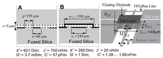
Figure 24.
Design schematic of a realized unit element. Cross-section of CPW Section A (left) and grounded CPW (varactor) section B (middle), both with the corresponding transmission line parameters of the proposed structure on the right side [185,227].
For its realization, fused silica with a height of hs = 700 µm, a relative permittivity of , and a dielectric loss factor of @16 GHz were used as the top and bottom layer, which were separated by spacers with a diameter of about 5 µm to determine the height of the LC cavity, which was filled afterwards with TUD-566. Although the whole structure was actually filled with the LC, Segments A without additional ground plane behave as a standard CPW line, since the thin LC layer is not affecting its properties significantly. The center conductor width was set to , while the gap between the center and adjacent conductors was set to . The total length of the phase shifter was 12.7 mm. A bias voltage of of up to 60 V is applied via the ITO biasing lines. By this, the LC can be tuned from the perpendicular pre-orientation to the parallel orientation, using the full anisotropy. The results of the S-parameter measurements versus frequency are shown in Figure 25. For a frequency of 20 GHz, more than a 130° differential phase shift has been achieved, accompanied with a of slightly more than 2 dB, thus obtaining a better than 60°/dB. Note that since a length of this loaded line phase shifter of 12.7 mm () provides > 130° at 20 GHz, a 360°-phase shifter would be
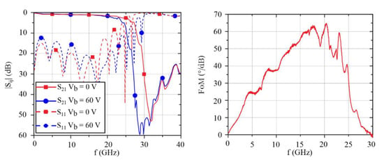
Figure 25.
Measured S-parameters for the two extreme tuning states for Vb = 0 V and Vb = 60 V and the versus frequency [185]. Reprinted from [2], Cambridge University Press, 2020.
Due to its small LC layer height hLC of 4.5 to 5 µm, the measured response time is less than 110 ms from zero bias to a fully tuned state, and is now less than 340 ms from the fully tuned state back to zero, which is significantly faster than for the IMSL with the same LC above. This experimental value of 340 ms for the second-generation LC TUD-566 agrees well with the theoretical values of 330 to 410 ms for 4.5 to 5 µm of the parallel-plate cell in Figure 8. It is somewhat slower than those measured for the single varcator of = 92 ms, using the first-generation LC GT3, because of its lower viscosity.
Using the aforementioned analysis method with the transmission line parameters , , , and for each Section A and B according to Figure 24, in order to calculate the effective line parameters for an input impedance around 50 Ohm, the differential phase shift obtained by using TUD-566 is about 124° at 20 GHz. The simulated switch-off response time is 319 ms, which agrees quite well with the experimental results. However, the resulting FoM of 108°/dB significantly overestimated the measured one above, because this analysis method does not deal with the low-pass filter like characteristic of the structure and the reduction of the Q-factor (reduction of more than 30% at 20 GHz [185]) due to cross currents and the resulting shunt inductance.
Another practical approach with slightly different unit elements of the periodic structure is reported in [175] for a loaded-line phase shifter with a total length of = 27 mm. It provided similar results. This time, a low-cost 700 µm thick BF33 glass () is used as the top and bottom substrate, forming a LC cavity of about 4 µm height filled with TUD-566. According to Figure 26, these varactors with a relatively large overlapping area of w × LOverlap are built up by metal bridges and the signal line of the CPW. These bridges connect the two ground planes of the CPW on the bottom substrate by using gold via pillars, creating a small grounded coplanar waveguide (gCPW) segment with an additional ground plane on the top substrate. For both ends of the bridge, a trapezoidal geometry was chosen for implementing the vias over a large area to reduce their resistance. The geometrical parameters are set to , , , , , and . The loaded-line phase shifter, which is built up by 38 identical unit elements, provides a differential phase shift of 360° at the operating frequency of 20 GHz with a bias voltage of of up to 30 V. By this, the LC can be tuned from the perpendicular pre-orientation to the parallel orientation, using the full anisotropy. The return loss was less than −20 dB and the maximum insertion loss was about < 5.5 dB, thus yielding a FoM of 65°/dB. The response times to change the phase of 360° is = 40 ms and = 260 ms, respectively. It agrees well with of the parallel-plate cell. The response times could further be reduced by using varactors with a thinner LC layer and/or a nematic LCs with lower rotational viscosity as for Merck’s third-generation LCs.
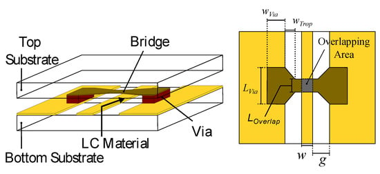
Figure 26.
Schematic of a LC varactor build up by a metal bridge on the top substrate (left), connecting the two ground planes of the CPW by vias and the signal line on the bottom substrate, filled with LC. Top view (right) [175].
Improved FoMs can be achieved by using a modified strip line arrangement on both layers according to Figure 27 (upper right) to reduce the shunt inductance of the loaded segments, but allowing a reduced input impedance. In this case, impedance matching sections are required at both ends for 50 Ω input and output ports. Due to the reduced shunt inductances, this approach provides much better results than the structure in Figure 24.
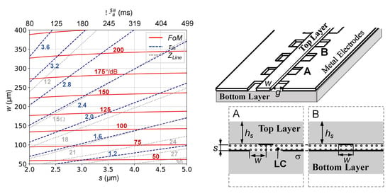
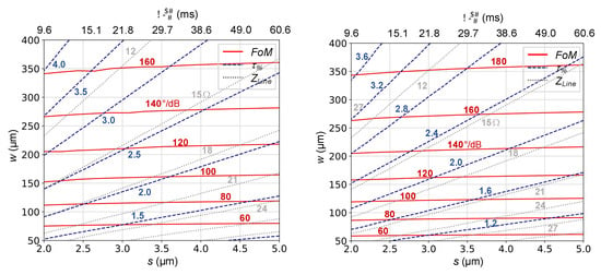
Figure 27.
Plots for designing CPW loaded-line structure given in the upper right picture. The varactors are filled with second-generation LC TUD-566 (upper left) and third-generation LC GT7-29001 (below) for 30 GHz (left) and 60 GHz (right). As the top and bottom layer, use is made of fused silica with height hs = 300 µm, relative permittivity of , and a dielectric loss factor of . The electrical conductivity of the metal parts is set to . A pre-orientation of the LC in the propagation direction was chosen. These plots exhibit curves of constant phase shifter figure-of-merit (, full red lines), orientation effectivity (dashed blue lines), and line impedance (dotted gray lines), depending on the strip line width (vertical axis) and the distance ≈ hLC (lower horizontal axis) between the metallic conductors and the decay time (upper horizontal axis).
As mentioned before, the slow-wave effect enables orientation effectivities greater than one, which refers to the tunability of a completely filled homogeneous gCPW or parallel plate waveguide. Here, the propagation constant is determined by the dielectric parameters of the LC. Using a loaded-line topology, the effective propagation constant can be increased by using proper and as independent design parameters. In order to achieve the same phase shift, the reduction in the required phase shifter length goes up to a factor of four for very thin layers and wide strip lines, as depicted in Figure 27. The plots show that the FoM is almost constant over the distance s between the conductors, which is slightly less than the effective LC layer height hLC, depending on the conductor thickness. Thus, for a width w = 200 µm, FoMs of about 130 and 115°/dB can be achieved using TUD-566 and GT7 at 30 GHz, respectively, and 138°/dB with GT7 at 60 GHz. As expected, the decay time for this modified loaded-line topology filled with GT7 is much faster than that with TUD-566. It is in the range of 10 to 35 ms for s = 2 to 4 µm. Note that the decay time given on the top axis is slightly different to the switch-off response time derived from the parallel capacitor cell in Figure 8, because the effective LC layer height hLC is a bit larger than s. For a wider width w, the FoM increases, but the line impedances decrease. Analogous to the analysis with the IMSL in Figure 18, the FoM is always better for the same design parameter at 60 GHz than for at 30 GHz.
As already mentioned, important requirements for phase shifters implemented in electrically steerable planar phased array antennas is the provision of a 360° differential phase shift and an overall size not exceeding λ0/2 × λ0/2 to fit behind a single antenna element. Even the length of a 360°-phase shifter exceeds λ0/2, it can be meandered or spiraled within this squared area. However, each bend of a line could cause additional losses. Therefore, a straight delay line phase shifter is always a preferred solution. This might be achieved by utilizing (1) phase shifters with less differential phase shift, i.e., physical length, or (2) by using the slow-wave effect as above, by which the phase velocity of the line can be reduced to miniaturize it by factor of two to five.
First, a 90°-phase shifter with reduced length compared to a 360°-phase shifter was used in combination with a MEMS switch at the end, as shown in Figure 28, which means a 0° or 180° phase shift of the reflected wave for OPEN or SHORT of the MEMS switch. Hence, this reflection-type phase shifter requires a 90° tunable delay line only to tune the overall phase shift continuously between 0° and 360°. In order to reduce the response time at the same time, this reflection-type phase shifter uses the loaded-line concept in Figure 24 with an LC layer height in between 4.5 and 5 µm.
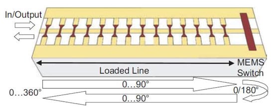
Figure 28.
Principle of the reflection-type phase shifter with a 90°-loaded line phase shifter and a MicroElectroMechanical Systems (MEMS) switch at the end [267,268].
This concept was proposed for the first time in [267,268] and realized in the W-band. The CPW line was processed on a 300 µm thick fused silica substrate, where the ground planes are made of a 5 µm thick gold layer, while the signal line is made of a 600 nm thick multi-metal Ti–TiN–Al–Ti–TiN layer with a 150 nm thick gold layer on top, creating a floating metal bridge. To realize the moveable bridge, and thus to form the thin LC cavity, photoresist was deposited above and around this multi-metal gold layer, before the gold parts such as the bridge, the pillars, or the grounds have been processed by using an electroplating process. Finally, the photoresist has been removed by using oxygen plasma. The LC has been filled under the MEMS bridges by using a micro-injector, which was kept in due to the capillary forces. The results of the S-parameter measurements of this loaded-line phase shifter in MEMS technology filled with GT3-23001 in the frequency range from 65 up to 95 GHz have been [267,268]: Matching is better than −15 dB, the maximum differential phase shift goes up from 100° to 240°, while the maximum varies between −2 and −4 dB. This results in a between 40°/dB and 60°/dB. The maximum biasing voltage was set to .
Investigations of the transient behavior of this loaded-line phase shifter in MEMS technology is shown in Figure 29, where the rise and decay of the measured differential phase shift with respect to its maximum in % at 77 GHz is plotted versus time t in ms for different temperatures. Meanwhile, the measured rise time (for 10 to 90% in ) is sparsely dependent on temperature and less than 2 ms; except for 6.8 ms for 10 °C, the measured decay time (for 90 to 10% in ) changes significantly with temperature: = 136, 69, 37, 17, 11, 7 and 5.2 ms for 10, 23, 30, 40, 50, 70, and 90 °C, respectively. The value at room temperature agrees well with = 62 to 77 ms for GT3-23001 in Figure 8 for hLC in between 4.5 and 5 µm.
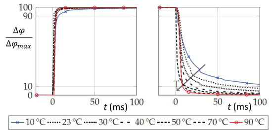
Figure 29.
Transient behavior of the loaded-line phase shifter in MEMS technology with the rise and decay of the measured differential phase shift with respect to its maximum in percentage at 77 GHz versus time for different temperatures [268].
Based on measurements of the reflection-type phase shifter with an MEMS switch at the end, the rise time and decay time were modeled in [268] by taking the following formulas: and , respectively. The last one reveals 0.33 ms and 26.64 ms for the 90% and 10% values, respectively. Both formulas were taken for the phase change rate of the phase shifter to simulate the beam-scanning duration of a phased array and reflectarray at 77 GHz, consisting of 38 × 38 radiating elements 0.51λ apart, for different scanning scenarios [268]. To scan the beam from −45° to +45°, it took 1 ms for the reflecctarray; however, this was accompanied with some higher side lobe levels and 9 ms (a beam-scanning rate of 10°/ms) for the phased array with lower side lobe levels. The difference is mainly because the path length between the feed and the unit cells on the reflectarray are different, and hence, so is the initial phase distribution, which has to be compensated first in the phase shifters of the phased array. Hence, for scanning the beam in a certain angle range, e.g., ±45°, not all phase shifters have to change its phase completely, i.e., 360° within or , depending on the start or aim position of the phase shifters for the scan. This means that the overall performance is governed by the distribution of the phase change rate rather than a minimum or maximum value. This means that the beam-scanning duration is always less than the decay time (maximum, worst case) or switch-off response time of the LC phase shifter.
Another option aims for miniaturized and fast tunable slow-wave phase shifters with thin LC layers ≤ µm, which can be realized either by a 0.35 μm CMOS process in connection with a CPW topology [71] or by using a nanowire membrane (NaM) [269] on top of the ground plane on the backside of an inverted microstrip line [81]. It is separated from the top substrate (glass) with the strip line and alignment layer by spacers, where the thin cavity between the NaM and glass of few µm only is filled later with LC. The schematic is shown in Figure 30. While the magnetic field is able to pass through the nanowires almost unperturbed, the electric field is confined in between the signal line and the nanowires. Hence, an increase of the equivalent capacitance of the transmission line is obtained, while the inductance remains unchanged, thus providing a slow-wave effect characterized by a decrease of the phase velocity . This slow-wave effect strongly enhances when the strip line is narrow to the end caps of the nanowires, i.e., when the LC layer height is very thin. The NaM technology allows the realization of tunable microstrip lines for 50 Ω design with an LC layer height of hLC ≤ 4 μm. This enables a significant reduction of the switch-off response time .
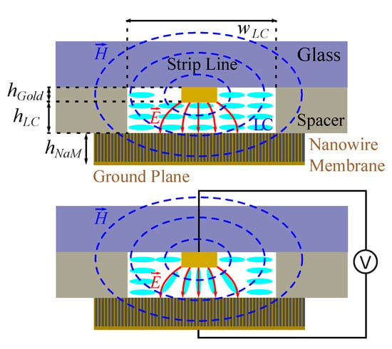
Figure 30.
Cross-section of a slow-wave microstrip line and its working principle: unbiased, quasi-perpendicular orientation (above) and full-biased, parallel orientation (below). It is built up by a nanowire membrane (NaM) on top of the ground plane, where the space in between the NaM and the top substrate (glass) with the strip line is filled with LC. The parameters are hNaM = 50 μm, hGold = 2 μm, hLC = 4 μm, and wLC = 500 μm [84].
For the realization [81,84], the microstrip line has been processed on a glass substrate by means of photolithography. Additionally, the alignment layer as well as cavity walls made of SU8 have been processed on the same substrate. The SU8 cavity walls are processed in a way that the LC layer height of hLC = 4 μm is ensured. Afterwards, the membrane with hNaM = 50 μm is glued to the already processed substrate. LC filling is done under vacuum conditions, and the parallel orientation is achieved by the application of an AC biasing voltage of 1 kHz to the strip line itself. Recent results in [84] looks very promising, since it shows a FoM of up to 70°/dB in a frequency range between 30 and 60 GHz, which is accompanied with < −15 dB and a miniaturization factor of more than 2 compared to an IMSL phase shifter, providing the same differential phase shift. The switch-on response time are 3.1 and 9.4 ms, and most decisively, the switch-off response time are 116 and 125 ms for GT3-23001 and GT7-29001, respectively. The switch-off response time is less than expected, which is due to just one alignment layer on the top substrate only. Hence, it can be reduced by even thinner LC layers µm and by more effective alignment layers on both inner surfaces of the cavity.
4.3. Flat-Panel Beam-Steering Antenna Arrays
This subsection will focus on flat-panel beam-steering antennas, combining state-of-the-art LCD technology with the introduced MLC technology, featuring very low power consumption and enabling the low-cost, large-scale manufacturing of large arrays with a great number of radiating elements, since the LC phase shifter stack is fabricated in standard LCD processes and established LCD production lines. Moreover, those smart antennas can provide combinations of frequency, polarization, and pattern agility as well as steered multiple beams.
A first small lab-scale demonstrator was already presented in [170,175] for a proof-of-concept at 17.5 GHz, using a 100 µm thick inverted microstrip delay line phase shifter. It is depicted in Figure 31 and Figure 32. It is a 2 × 2 microstrip patch array with an element spacing of 0.65λ0 × 0.65λ0. The overall thickness is 1.5 mm only, where the four spiraled 360°-delay line phase shifters are on the backside together with an SMA connector for the RF signal and a four-pin DC biasing connector to control the four delay line phase shifters. These inverted microstrip line phase shifters have to be spiraled in order to implement them within the limited area beneath the radiating element, since their total length is about for a 360°-phase shift. Their FoM is around 105°/dB without noticeable coupling at the bends. The insertion loss is in a range between 3.5 and 4.25 dB at 17.5 GHz.
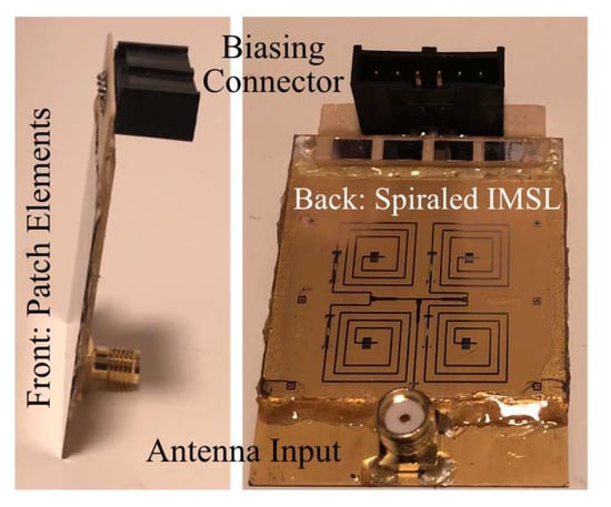
Figure 31.
First realized two-dimensional electronic steerable antenna array using a spiraled IMSL phase shifter with 100 µm LC layer height, being processed similar to LCD technology [170,175]. Side view of the array with an overall thickness of 1.5 mm only (left). Bottom view with the four spiraled IMSL lines, the feeding network, and four thin bias lines (not visible) on the substrate as well as an SMA connector for the RF signal and a four-pin DC connector to control the four delay line phase shifters (right). Courtesy of ALCAN Systems GmbH.
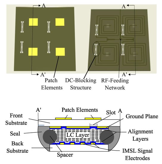
Figure 32.
Schematic of the 2 × 2 microstrip patch array with an element spacing of 0.65λ0 × 0.65λ0 [170,175]. Front view with the four patch elements (above, left). Back view with the spiraled IMSL lines (above, right). Cross-section of the array (below).
The assembly of this lab-scale demonstrator consists of three stacked substrates according to Figure 32, where the LC material layer of 100 µm thickness is sandwiched in between two 700 μm thick Borofloat glass (front and back) substrates with relative permittivity and dielectric loss tangents of 4.65 and 0.008, respectively. Both sides of a large glass substrate are processed one by one by using the same lithography processes, which are chromium (Cr)/gold (Au) evaporation, photolithography, Au plating, and wet etching. When the lithography is completed, the substrate is diced precisely within ±5 µm accuracy into two pieces [170]. On the front glass substrate, 2 × 2 microstrip patches made of gold are processed on top, and on the backside, a ground plane is coated with a thin polyimide film for pre-alignment of the LC. On the back substrate, the spiraled microstrip lines for 360° phase shifting are processed within the limited area; then, there is the RF feeding network by using standard λ/4-impedance transformers and four thin highly resistive Cr bias lines for controlling each phase shifter individually, which are again coated with a thin polyimide film for pre-aligning the LC molecules on top. As spacers, micro pearls with 100 µm diameter are used to maintain a cavity of constant thickness. Then, after gluing both glass substrates together and sealing them, the LC TUD-566 is filled in. The signals of the four microstrip delay lines are coupled through the first polyimide film, the LC layer, and the second polyimide film, through the four slots in the ground plane and then through the front glass to the radiating elements. Test measurements with this aperture-coupled array exhibited an antenna matching of around −20 dB for broadside (unbiased), going down to −15 dB when it is steered at 17.5 GHz. Figure 33 exhibits the far-field radiation pattern in an anechoic chamber, where the antenna is mounted on top of a turn table and electronically scanned within ±25° in both planes. Since it is a small array with 2 × 2 elements only and with a relatively large element spacing of 0.65λ0, the antenna gain reduces by about 2 dB and the side lobe level (SLL) increases to −4 dB at wide-scanning angles Θm = ±25°. Both are confirmed by the simulations [170,175]. When the main beam is steered to Θm = −45°, a grating lobe occurs at +45°. The measured beam-scanning duration is about 150 s to tilt the main beam from Θm = 0° (broadside) to Θm = 45° and vice versa. This empirical result verifies that the beam-scanning duration is lower than the response time of the delay line, which is about 180 s for the LC TUD-566, as discussed above and found out in [268].
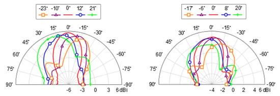
Figure 33.
Measured antenna gain patterns in the E (left) and H (right) principal planes [170,175]. Reprinted from [2], Cambridge University Press, 2020.
The larger size of the proposed array and a larger spacing between the radiating elements d = 0.65λ0 provides higher gain, while a smaller spacing d = 0.55λ0 allows a wider scanning range, in which the antenna can be steered with SLL less than −11 dB, as can be seen from the simulations in Figure 34.
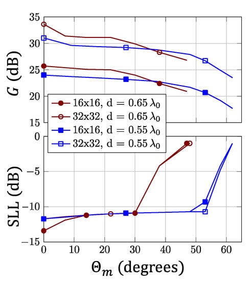
Figure 34.
Antenna gain G and side lobe level (SLL) versus main beam direction Θm of a 16 × 16 and 32 × 32 array of the proposed topology with two spacings—d = 0.65λ0 and d = 0.55λ0—between the radiating elements at 17.5 GHz [175]. Reprinted from [2], Cambridge University Press, 2020.
Based on these scientific results, ALCAN’s first-generation antenna was fabricated with an IMSL phase shifter stack, using a 100 µm LCD process and a modular concept, where several basic modules of 8 × 8 radiating elements build up the ESA with an appropriate size to meet the application’s specific requirements. The feasibility was first demonstrated in 2018 with a flat-panel antenna array in Figure 35 that allowed steering the antenna beam between different Ku-band satellites in geostationary orbit for television reception with a bandwidth of about 2.5 GHz [253]. To improve the beam-scanning rate, a new third-generation LC was used with much lower viscosity, with which the beam could be scanned within Θm = ±60° in less than 20 s, i.e., a beam-scanning rate of 6°/s.
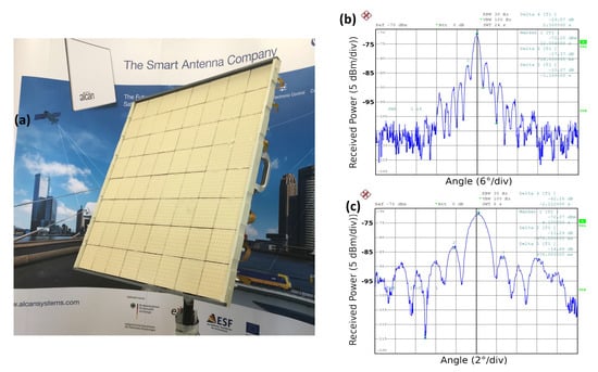
Figure 35.
(a) Ku-band TV reception demonstrator with ALCAN’s first-generation antenna to steer the beam between different GEO satellites, using a 100 µm LCD process for the phase shifter stack. (b) Horizontal and (c) vertical antenna pattern for a beam in the boresight direction (note the different angular scales) [253]. Courtesy of ALCAN Systems GmbH.
To speed up the response times significantly, and hence, the beam-scanning duration to single-digit milliseconds, ALCAN’s second-generation antenna for Ka-band satellite communications made use of a phase shifter stack again, but this time, it was being filled into loaded-delay lines similar to the one in Figure 27 with LC varactors of hLC ≤ 4 µm, with some modifications in the design for simpler implementation and improvements in the FoM. However, details cannot be published yet because of IP issues. However, this concept enables a lower loss and more compact size. Experimental investigations indicate an insertion loss of a phase shifter of about 3 dB at 30 GHz for a phase shift of 400°, and hence, a FoM > 120°/dB over a bandwidth of more than 2.5 GHz. The switch-off response time depends strongly on the liquid crystal mixture, which is a new third-generation LC from Merck with a bit larger ratio of rotational viscosity over the elastic constant than GT7, which was specifically synthesized for this application: with current design choices, it is in the range of 30 ms for an hLC of about 4 µm at room temperature. It should be noted that the switch-on response times are an order of magnitude faster and the overall performance is governed by the distribution of the phase change rate rather than a minimum or maximum value [179]. Therefore, it was not surprising that the empirical result for the beam-steering duration of phased arrays based on these phase shifter stacks was about 10 ms to scan the beam from −60° to +60° (beam-scanning rate of 12°/ms); i.e., it was less than the switch-off response time of 30 ms (maximum), which consolidates our experience.
Again, use is made of the modular concept with several basic modules of 8 × 8 radiating elements with an appropriate size to meet the application’s specific requirements. Each module is built up in different stacks, which mainly consist of a feeding network stack, a LC-phase shifter stack, and a radiator stack, where all parts are designed independently and in a modular fashion. Figure 36 shows the schematic of an antenna module. At the end of the assembly, a radom will cover the antenna on top and a Low-Noise Amplifier (LNA)/Power Amplifier (PA) with an Rx/Tx-modem as well as the control unit is placed behind the feeding network. Herein, the core LC-phase shifter stack consists of two glass sheets with the metallic structures and the alignment layers separated by spacers where the LC material is filled in between. It is fabricated with standard LCD processes by an LCD manufacturing company. This allows large-scale fabrication as well as virtually any aperture size, including segments or antenna groups, thus providing a cost advantage [179,246].
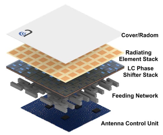
Figure 36.
Microwave Liquid Crystal (MLC)-based phased array layout for a basic module. Courtesy of ALCAN Systems GmbH.
This technology is entirely passive, and biasing requires only low power and takes advantage of existing LCD driver technology. Controlling up to 512 radiating elements will consume a power of less than ½ Watt, which represents a 30 times improvement over a standard semiconductor-based phase shifter [256]. Moreover, by leveraging the existing mass production capabilities of LCD production lines, as well as the low marginal cost of producing additional types of LC panels, ALCAN claims to be able to reduce the LC phase shifter costs by 100 times to around 300 $/m2 compared to semiconductor-based phase shifter costs, which are estimated to be around 30.000 $/m2 when using 30 cm diameter wafers [255,256]. At present, an antenna prototype is aimed for satellite ground terminals, which are this time made up by stacking unit tiles, where each identical tile has a fixed number of radiating elements (typically 256, 512, or 1024). The Rx (blue) and Tx (red) aperture for non-GEO ground stations in Figure 37 will be operating in the Ka-band. The antenna will be mounted onto a roof and will provide more than 150 Mpbs throughput, while the power consumption without Low-Noise Block or Block UpConverter (LNB or BUC), and modem is below 30 W.
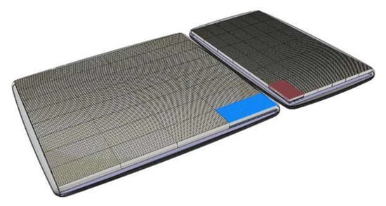
Figure 37.
Microwave Liquid Crystal (MLC)-based receive (blue) and transmit (red) ESAs made up of a variable number of tiles, where each tile has a fixed number of radiating elements, depending on requirements. This visualization shows one possible configuration for a high-gain non-GEO antenna. Courtesy of ALCAN Systems GmbH.
At first, ALCAN’s second-generation antenna was aimed for ground and user terminals of MEO/LEO satellite constellations only [179]. However, because of its low power consumption, potentially low costs for the phase shifter stack, low weight, and small form factor, it is also viable for 5G mm-wave systems, despite the “slow” beam-steering duration to scan the beam within ±60° in about 10 ms seeming to be a limitation factor at first glance compared to much faster beamformer ICs. However, End-to-End (E2E) latency is not equivalent to the antenna beam-steering speed, as in most of the cases they are independent. Thus, in many URLLC use cases with E2E latency requirements less than 1 ms, beam-steering is not required dynamically. Considering latency requirements of 10 ms for eMBB use cases such as broadband access in dense areas or indoor ultra-high broadband access, and assuming that users are moving by a car or walking, this beam-steering speed is sufficient to keep track and to fulfill E2E latency requirements. Even for high-speed mobile vehicles, e.g., trains and airplanes, the beam-scanning rate of about 12°/ms seems to be fast enough to maintain connection. Possible beam-steering scenarios and possible beam-forming architectures for mm-wave antenna arrays are given in [255]. Figure 38 above sketches the fully analog beam-steering antenna (single-beam ESA) for Point-to-Point (PtP) links as for satellite communications, where one RF chain is used for the entire array, offering the best performance in terms of cost and simplicity. Figure 38 below presents a hybrid analog/digital beam-steering antenna architecture with multi-beam capability (multi-beam ESA) for Point-to-Multipoint (PtM) links such as Massive–MIMO base stations. A multi-beam ESA is demonstrated under the public link [257]. Here, one RF chain is used per subarray, where a single RF chain comprises one PA, one LNA, and a T/R (Transmit/Receive) switch and shall be compliant with 5G power levels and TDD requirements [246,255]. This hybrid architecture offers the best compromise between beam-forming flexibility and RF frontend cost/complexity. It requires less RF components compared to MMIC-based hybrid or fully digital beam-forming antenna solutions. Moreover, the power consumption is less. Thus, for an EIRP of about 50 dBm, the MLC technology-based 8 × 8 module, operating at the 28 GHz, consume less than 5.5 Watts compared to 20 Watts of an Si-based 8 × 8 array [247,255]. This becomes more significant for larger arrays, since the MLC-based array does not increase linearly with increasing number of radiating elements, i.e., phase shifters. For example, in case of a 16 × 16 array with 4 beams and a minimum EIRP of 60 dBm, the MLC-based antenna has an overall power consumption of around 19 Watts compared to 65 Watts for antenna arrays based on silicon-based ICs [247]. Some usage scenarios are given in [255].
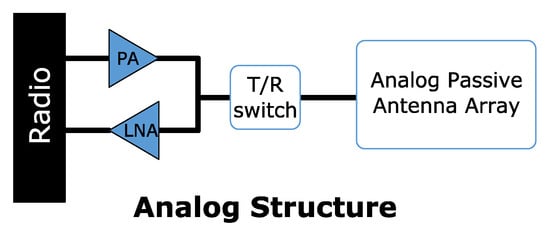
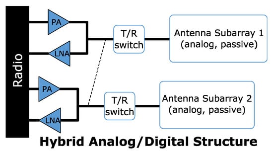
Figure 38.
Single-beam ESA with a fully analog architecture for point-to-point communications (above) and multi-beam ESA with hybrid analog/digital architecture, using subarrays, for point-to-multipoint communications (below) [255].
5. Conclusions
This paper presented some fundamentals and the progress of microwave liquid crystals, concerning its performance metric with a focus on its response times, as well as for phase shifters in different topologies, starting from well-known LC-tuned waveguide phase shifters and planar inverted microstrip delay lines toward innovative loaded line and nanowire membrane-filled LC concepts with the newest results, featuring different microwave performances and response times, ranging from tens of seconds down to few tens of milliseconds. For manufacturing low-cost large-scale ESAs with very low power consumption for single- and multiple-beam steering, low-profile planar loaded-line phase shifter stacks with 4 µm thin integrated MLC varactors with switch-off response times of about 30 ms for 400° differential phase shift at room temperature are currently assembled into multi-stack, flat-panel, beam-steering phased arrays, where the MLC phase shifter stacks with a FoM > 120°/dB over 2.5 GHz bandwidth are fabricated in a standard LCD process. Beam-steering within ±60° is in the range of 10 ms in practice, which is less than the response time above, since not all phase shifters of the array require a full 360° phase shift at the same time during the beam-steering process. In a few cases, it might need more than 10 ms to reduce the side lobe level for fitting the mask requirements. Further developments are going into three directions:
- Next-generation microwave LCs are aiming for higher low-temperature stability in the range of −30 °C, higher anisotropy in relative permittivity up to 1.2, and a larger ratio of rotational viscosity over the elastic constant for even faster switch-off response times of less than 25 ms for an LC layer height of 4 µm.
- Progress in the processing and manufacturing of the phase shifter stack (1) with a lower LC layer height hLC < 2.5 µm, which reduces the response time significantly, down to below 10 ms, without affecting the other performance parameters, (2) using thinner glass with low dielectric constant and low dielectric losses, and (3) with compacter loaded lines for 360° phase shift.
- Progress in the assembly technology of the whole electronically steerable antenna, including the electronics for the antenna control unit, the feeding network, and the radiator stack.
With the modular concept and the hybrid analog/digital architecture, these smart antennas are flexible in size to meet the specific requirements for operating in future satellite ground and user terminals, but also in 5G mm-wave systems.
6. Patents
- Jakoby, R.; Karabey, O.H.; Goelden, F.; Manabe, A. Electronically steerable planar phased array antenna. US20190260139A1, 2011.
- Jakoby, R.; Karabey, O.H.; Hu, W. Phase shift device. US20190103644A1, 2013.
- Gölden, F.; Gäbler, A.; Karabey, O.H. Radio frequency phase shifting device. US20200044300A1, 2018.
- Gölden, F.; Gäbler, A.; Karabey, O.H. Funkfrequenz phasen ver schieb ungs vor richt ung. EP3609017A1, 2018.
Author Contributions
Conceptualization, R.J.; methodology, R.J.; software, A.G.; validation and investigation, R.J., A.G. and C.W.; writing—original draft preparation, R.J.; writing—review and editing, R.J.; supervision, R.J.; project administration, R.J., A.G. and C.W.; funding acquisition, R.J., A.G. and C.W. All authors have read and agreed to the published version of the manuscript.
Funding
The research presented in this paper was partially funded by the FEDERAL MINISTRY FOR ECONOMIC AFFAIRS AND ENERGY (BMWi) in four projects within the LIQUIDA (Liquid Crystal Antenna Array for Space Applications) program, coordinated by the German Aerospace Center: FKZ 50YB0921, FKZ 50YB0620 &, FKZ 50YB1316 and FKZ 50YB1102. Additionally, in the LISA-ES project FKZ: 50 YB 1113. ALCAN Systems received seed funding in part through the EXIST Forschungstransfer program (project FKZ 03EFDHE026) of BMWi.
Acknowledgments
The authors gratefully acknowledge Merck KGaA for supplying Liquid Crystal mixtures. We acknowledge support by the German Aerospace Center and the FEDERAL MINISTRY FOR ECONOMIC AFFAIRS AND ENERGY (BMWi) as well as the Open Access Publishing Fund of Technische Universität Darmstadt.
Conflicts of Interest
The authors declare no conflict of interest.
Appendix A
Information and communication technologies (ICT) are the foundation of growth and development in the modern global economy and society, striving to bring robust connectivity to all corners of the globe. New means of connectivity, i.e., enhanced and new wireless platforms and network architectures, together with innovative wireless technologies promise improved coverage, greater capacity, higher data rates, more efficient use of spectrum resources, much quicker round-trip times or lower latency, higher system reliability, and more flexibility for the effective delivery of the ICT services. This will open up new applications, where the major market drivers beyond 2020, which trigger a massive number of use cases are [4,270,271]:
- ▪
- Mobile Internet (MI) focused on people-oriented communications with use cases such as Ultra-High Density (UHD) and 3D video, augmented reality, virtual reality, online gaming, mobile cloud, remote computing, tactile internet, 3D connectivity to aircrafts and drones, collaborative robots, smart office and
- ▪
- Internet of Things (IoT), including Machine-to-Machine (M2M) and Device-to-Device (D2D) communications, which provides communications between things AND between things and people with use cases such as smart grid and critical infrastructure monitoring, mobile surveillance, environmental monitoring, industrial automation, eHealth services, smart wearables and smart body area networks, sensor networks, smart homes/buildings, smart cities, smart transportation, self-driving and connected cars (Internet of Vehicles).
All these use cases can be grouped into three usage scenarios [4,270], or generic 5G services [271], addressing different use case characteristics, as illustrated in Figure A1.
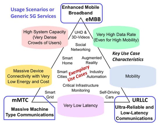
Figure A1.
Usage scenarios (generic 5G services) for mobile communications beyond 2020 with key use case characteristics and some exemplary use cases.
The evolution of wireless communications is primarily driven by the anticipated data traffic explosion and its economical perspective. Some drivers, characteristics, and trends that are expected to impact the anticipated traffic growth are given in detail in the Report ITU-R M.2370 [272], containing global international mobile telecommunications (IMT) traffic beyond 2020 from several sources. It reaches 62 EB/57 EB, 607 EB/543 EB, and 5016 EB/4394 EB with/without M2M traffic in 2020, 2025, and 2030, respectively. The network capacity unit ExaByte (EB) is 1018 (=1 Trillion) Bytes. This means a compounded annual growth rate (CAGR) of around 55% in 2020 to 2030 with and without M2M traffic, respectively. Hence, global IMT traffic will grow in the range of 10 to 100 times from 2020 to 2030, where M2M will have a traffic volume of about 7% and 12% of the total one in 2020 and 2030, respectively. By far, the largest traffic volume will be consumed by video usage with ultra-high resolution. Video streaming will account for almost 75% of all global mobile traffic, being more than 4.2 times and 6 times than non-video in 2025 and 2030, respectively. In Report ITU-R M.2370 [272] three major drivers have been identified, influencing the growth of future mobile traffic. All are expected to evolve over time. These three major drivers are:
- ▪
- enhanced mobile broadband, in particular by video usage with 75% of all global mobile traffic,
- ▪
- application uptake, i.e., the rate at which applications are being adopted, e.g., annual global downloading of applications was about 270 billion apps in 2017 and
- ▪
- device proliferation, accompanied with an evolution toward ever smarter mobile devices in different form factors and with continuously enhanced capabilities and intelligence, which require increasing bit rates and bandwidth.
Globally, the growth of wireless devices, accessing mobile networks worldwide, will grow significantly. Thus, [272] estimates the global mobile subscriptions of 10.7 billion in 2020, 13.8 billion in 2025, and 17.1 billion in 2030, respectively. Together with the estimated number of mobile connected M2M devices, numbers will be around 7 billion in 2020, 34 billion in 2025, and 97 billion in 2030, respectively. Hence, it is expected that the total number of devices connected by global mobile communications networks will surpass 100 billion by 2030. Moreover, the popularity of ultra-high resolution and large screens as well as the increasing number of high-performance smart devices such as smartphones and tablets, together with the growth of mobile subscriptions will dramatically increase the mobile traffic volume consumed by each user. [272] estimates that each subscriber will consume 5.3 GB, 39.4 GB, and 257.1 GB of data traffic per month in average in 2020, 2025, and 2030, respectively.
Beyond the major market and mobile traffic growth drivers, innovative wireless technologies will be a critical component in this development, which opens up new applications. In this frame, ICT are advancing in the following key areas and technologies [2,270,271,272,273,274]:
- ▪
- Wireless communication platforms and infrastructure such as 5G (IMT-2020) systems and beyond, High-Throughput Satellites (HTS) in geostationary (GEO) or Medium Earth Orbits (MEOs), Low Earth Orbit (LEO) satellite mega-constellations, High Altitude Platforms (HAPS) and future hybrid terrestrial–satellite networks will enable new forms of connectivity for the delivery of broadband services and the possibility of being always connected. Their evolution, key technology drivers, the markets, and perspectives are summarized in [2].
- ▪
- Spectrum resources: in order to cope with the higher traffic capacity and higher typical user data rate in 5G and in mobile satellite networks, considerably more spectrum is required than currently available. Spectrum has been in the past and will be also in the future one of the most valuable resources for mobile communications. Therefore, agencies and standardization organizations worldwide aim for international harmonized spectrum and full-spectrum access, especially above 6 GHz. Hence, beyond the sub-6 GHz bands for 5G in Europe 3.4–3.8 GHz, USA 3.1–3.55 GHz and 3.7–4.2 GHz, Japan 3.6–4.2 GHz and 4.4–4.9 GHz and China 3.3–3.6 GHz, 4.4–4.5 GHz and 4.8–4.99 GHz for 5G Phase I, frequency bands in the mm-wave range are already foreseen for 5G Phase II: in Europe 24.25–27.5 GHz and 31.8–33.4 GHz, USA 27.5–28.35 GHz and 37–40 GHz, Japan 27.5–29.5 GHz, 4.4–4.9 GHz, China 24.75–27.5 GHz, South Korea 26.5–29.5 GHz [275]. The technical feasibility of radio interface technology and systems operating in these frequency bands, taking into account propagation characteristics, antenna technology, active and passive components, physical layers, and medium access control design as well as deployment architectures, are carried out by simulations and performance tests and trials. Some are published in [271,276,277,278,279]. In Europe, the European Telecommunications Standards Institute (ETSI) is working to facilitate the use of the E-Band from 71–76 GHz and 81–86 GHz, and in the future, on the channelization of the W-band from 92 to 114.5 GHz and the D-band from 130 to 174.8 GHz for large-volume (high capacity) backhaul and front-haul systems as well as for innovative solutions for fixed broadband access [279]. Most of the HTS in GEO and MEO make efficient use of both, Ku-band and Ka-band (e.g., O3b downlink 17.7–20.2 GHz, uplink 27.5–30 GHz). Low Earth Orbit (LEO) high-throughput satellite constellations also aiming to operate in the Ku-band and Ka-band.
- ▪
- Network architectures: while previous generations of wireless networks are characterized by fixed radio parameters and spectrum blocks, software advances, and other complementary technologies will increase the flexibility, configurability, and efficiency of services such as cloud-radio access network (RAN), heterogeneous networks, network slicing, and network function virtualization (NFV) [270,271,280,281].
- ▪
- Integrated access node and backhaul design will enable the ultra-dense networking of radio nodes, where such nodes will need to access and self-organize available spectrum blocks for both access and backhauling. This capability will be a key for enabling high-frequency spectrum radio access. It will allow for the best delivery of services and to speed up the creation of massive-scale services and applications with flexibility, including ubiquitous ultra-broadband network infrastructure, mass-scale cloud architectures, ultra-dense radio networking with self-backhauling, M2M and D2D communications, and dynamic radio access infrastructure sharing [280].
- ▪
- Programmable/flexible air interfaces will be enabled by various advanced waveform technologies combined with advances in modulation and coding as well as advances in multiple access schemes such as filtered OFDM (Orthogonal Frequency Division Multiplexing), filter bank multi carrier, pattern division multiple access, sparse code multiple access, interleave division multiple access and beam division multiple access (BDMA) [270,271,274,282]. These schemes are essential to achieve continuing improvements in spectral efficiency, which correspondingly increases the capacity of the system. Moreover, flexible uplink/downlink resource allocation such as TDD–FDD joint operation and dynamic TDD (FDD/TDD = Frequency/Time Division Duplex) will address the growing traffic demand and allow more efficient and flexible use of radio resources. This could also be attained by advanced RF-domain processing, e.g., using single-frequency full-duplex radio technologies, where simultaneous transmission and reception on the same frequency with self-interference cancellation could increase spectrum efficiency significantly. Improvements in all these areas will drive overall network costs down while achieving improved energy efficiency [270,274,280,281]. Moreover, smart antenna and new reconfigurable hardware concepts, in particular at higher frequencies are required for programmable/flexible air interfaces.
References
- Maune, H.; Jost, M.; Wiens, A.; Weickhmann, C.; Reese, R.; Nikfalazar, M.; Schuster, C.; Franke, T.; Hu, W.; Nickel, M.; et al. Tunable Microwave Component Technologies for SatCom-Platforms. Frequenz 2017, 71, 129–142. [Google Scholar] [CrossRef]
- Jakoby, R.; Rehder, G.; Ferrari, P.; Karabey, O.H.; Maune, H. Reconfigurable Circuits and Technologies for Smart Millimeter-Wave Systems; Cambridge University Press: Cambridge, UK, 2020. [Google Scholar]
- Osseiran, A.; Monserrat, J.F.; Marsch, P. 5G Mobile and Wireless Communications Technology; Cambridge University Press: Cambridge, UK, 2016; ISBN 978-1-107-13009-8. [Google Scholar]
- Xiang, W.; Zheng, K.; Shen, X. 5G Mobile Communications; Springer International Publisher: Cham, Switzerland, 2017; ISBN 9783319342061. [Google Scholar]
- Vorhaus, J.L.; Pucel, R.A.; Tajima, Y. Monolithic Dual-Gate GaAs FET Digital Phase Shifter. IEEE Trans. Microw. Theory Tech. 1982, 30, 982–992. [Google Scholar] [CrossRef]
- Shih, S.E.; Duan, D.; Fordham, O.; Törnquist, K.; Zeng, X.; Chang, P.C.; Tsai, R.S. A W-Band 4-Bit Phase Shifter in Multilayer Scalable Array Systems. In Proceedings of the 2007 IEEE Compound Semiconductor Integrated Circuits Symposium, Portland, OR, USA, 14–17 October 2007; pp. 1–4. [Google Scholar] [CrossRef]
- Kang, D.-W.; Kim, J.-G.; Min, B.-W.; Rebeiz, G.M. Single and Four-Element Ka-Band Transmit/Receive Phased-Array Silicon RFICs With 5-bit Amplitude and Phase Control. IEEE Trans. Microw. Theory Tech. 2009, 57, 3534–3543. [Google Scholar] [CrossRef]
- Yang, J.G.; Yang, K. Ka-Band 5-Bit MMIC Phase Shifter Using InGaAs PIN Switching Diodes. IEEE Microw. Wirel. Compon. Lett. 2011, 21, 151–153. [Google Scholar] [CrossRef]
- Deng, X.; He, Z.; Yuan, S.; Shao, Z.; Liu, L. W-band high bit passive phase shifter for automotive radar applications in BiCMOS. In Proceedings of the International Conference on Computational Problem-Solving (ICCP), Chengdu, China, 21–23 October 2011; pp. 115–119. [Google Scholar] [CrossRef]
- Chen, N.; Zhen, J.; Pang, Q. A millimeter-wave GaAs 5-bit MMIC digital phase shifter. In Proceedings of the 2013 International Workshop on Microwave and Millimeter Wave Circuits and System Technology, Chengdu, China, 24–25 October 2013; pp. 444–447. [Google Scholar] [CrossRef]
- Barker, S.; Rebeiz, G.M. Distributed MEMS true-time delay phase shifters and wide-band switches. IEEE Trans. Microw. Theory Tech. 1998, 46, 1881–1890. [Google Scholar] [CrossRef]
- Barker, N.S.; Rebeiz, G.M. Optimization of distributed MEMS phase shifters. In Proceedings of the 1999 IEEE MTT-S International Microwave Symposium Digest (Cat. No.99CH36282), Anaheim, CA, USA, 13–19 June 1999; Volume 1, pp. 299–302. [Google Scholar] [CrossRef]
- Kim, H.-T.; Park, J.-H.; Lee, S.; Kim, S.; Kim, J.-M.; Kim, Y.-K.; Kwon, Y. V-band 2-b and 4-b low-loss and low-voltage distributed MEMS digital phase shifter using metal-air-metal capacitors. IEEE Trans. Microw. Theory Tech. 2002, 50, 2918–2923. [Google Scholar] [CrossRef]
- Scardelletti, M.C.; Ponchak, G.E.; Varaljay, N.C. MEMS, Ka-band single-pole double-throw (SPDT) switch for switched line phase shifters. In Proceedings of the IEEE Antennas and Propagation Society International Symposium (IEEE Cat. No.02CH37313), San Antonio, TX, USA, 16–21 June 2002; Volume 2, pp. 2–5. [Google Scholar] [CrossRef][Green Version]
- Stehle, A.; Georgiev, G.; Ziegler, V.; Schoenlinner, B.; Prechtel, U.; Seidel, H.; Schmid, U. RF-MEMS Switch and Phase Shifter Optimized for W-Band. In Proceedings of the European Microwave Conference, Amsterdam, The Netherlands, 27–31 October 2008; pp. 104–107. [CrossRef]
- Pillans, B.; Coryell, L.; Malczewski, A.; Moody, C.; Morris, F.; Brown, A. Advances in RF MEMS phase shifters from 15 GHz to 35 GHz. In Proceedings of the IEEE MTT-S International Microwave Symposium, Montreal, QC, Canada, 17–22 June 2012; pp. 1–3. [Google Scholar] [CrossRef]
- Reyaz, S.; Samuelsson, C.; Malmqvist, R.; Kaynak, M.; Rydberg, A. Millimeter-wave RF-MEMS SPDT switch networks in a SiGe BiCMOS process technology. In Proceedings of the 2012 7th European Microwave Integrated Circuit Conference, Amsterdam, The Netherlands, 29–30 October 2012; pp. 691–694. [Google Scholar]
- Somjit, N.; Stemme, G.; Oberhammer, J. Performance optimization of multi-stage MEMS W-band dielectric-block phase-shifters. In Proceedings of the 2012 7th European Microwave Integrated Circuit Conference, Amsterdam, The Netherlands, 29–30 October 2012; pp. 433–436. [Google Scholar]
- Chang, C.; Chen, Y.; Hsieh, S. A V-Band Three-State Phase Shifter in CMOS-MEMS Technology. IEEE Microw. Wirel. Compon. Lett. 2013, 23, 264–266. [Google Scholar] [CrossRef]
- Psychogiou, D.; Peroulis, D.; Li, Y.; Hafner, C. V-band bandpass filter with continuously variable centre frequency. IET Microw. Antennas Propag. 2013, 7, 701–707. [Google Scholar] [CrossRef]
- Ozturk, E.; Nemati, M.H.; Kaynak, M.; Tillack, B.; Tekin, I. SiGe process integrated full-360° microelectromechanical systems-based active phase shifter for W-band automotive radar. IET Microw. Antennas Propag. 2014, 8, 835–841. [Google Scholar] [CrossRef]
- Zahr, A.H.; Blondy, P.; Zhang, L.; Dorion, C.; Stefanini, R.; Courtade, F.; Pressecq, F. A DC-30 GHz high performance packaged RF MEMS SPDT switch. In Proceedings of the 2015 European Microwave Conference (EuMC), Paris, France, 7–10 September 2015; pp. 1015–1017. [Google Scholar] [CrossRef]
- Shah, U.; Decrossas, E.; Jung-Kubiak, C.; Reck, T.; Chattopadhyay, G.; Mehdi, I.; Oberhammer, J. Submillimeter-Wave 3.3-bit RF MEMS Phase Shifter Integrated in Micromachined Waveguide. IEEE Trans. Terahertz Sci. Technol. 2016, 6, 706–715. [Google Scholar] [CrossRef]
- Chakraborty, A.; Gupta, B. Paradigm Phase Shift: RF MEMS Phase Shifters: An Overview. IEEE Microw. Mag. 2017, 18, 22–41. [Google Scholar] [CrossRef]
- Koul, S.K.; Bhat, B. Microwave and Millimeter Wave Phase Shifters; Artech House: Norwood, MA, USA, 1991. [Google Scholar]
- Patton, C.E. Hexagonal ferrite materials for phase shifter applications at millimeter wave frequencies. IEEE Trans. Magn. 1988, 24, 2024–2028. [Google Scholar] [CrossRef]
- Nafe, A.; Shamim, A. An Integrable SIW Phase Shifter in a Partially Magnetized Ferrite LTCC Package. IEEE Trans. Microw. Theory Tech. 2015, 63, 2264–2274. [Google Scholar] [CrossRef]
- Wang, Z.; Song, Y.-Y.; Sun, Y.; Bevivino, J.; Wu, M.; Veerakumar, V.; Fal, T.J.; Camley, R.E. Millimeter wave phase shifter based on ferromagnetic resonance in a hexagonal barium ferrite thin film. Appl. Phys. Lett. 2010, 97, 072509. [Google Scholar] [CrossRef]
- Kozyrev, A.B.; Ivanov, A.V.; Soldatenkov, O.I.; Tumarkin, A.V.; Razumov, S.V.; Aigunova, S.Y. Ferroelectric (Ba,Sr)TiO3 thin-film 60-GHz phase shifter. Tech. Phys. Lett. 2001, 27, 1032–1034. [Google Scholar] [CrossRef]
- Shi, S.; Purden, J.; Lin, J.; York, R.A. A 24 GHz wafer scale electronically scanned antenna using BST phase shifters for collision avoidance systems. In Proceedings of the 2005 IEEE Antennas and Propagation Society International Symposium, Washington, DC, USA, 3–8 July 2005; Volume 1B, pp. 84–87. [Google Scholar] [CrossRef]
- Velu, G.; Blary, K.; Burgnies, L.; Marteau, A.; Houzet, G.; Lippens, D.; Carru, J.-C. A 360° BST Phase Shifter with Moderate Bias Voltage at 30 GHz. IEEE Trans. Microw. Theory Tech. 2007, 55, 438–444. [Google Scholar] [CrossRef]
- Sigman, J.; Nordquist, C.D.; Clem, P.G.; Kraus, G.M.; Finnegan, P.S. Voltage-Controlled Ku-Band and X-Band Tunable Combline Filters Using Barium-Strontium-Titanate. IEEE Microw. Wirel. Compon. Lett. 2008, 18, 593–595. [Google Scholar] [CrossRef]
- Gevorgian, S. Ferroelectrics in Microwave Devices, Circuits and Systems: Physics, Modeling, Fabrication and Measurements; Springer Science & Business Media: London, UK, 2009. [Google Scholar]
- Choi, K.; Courreges, S.; Zhao, Z.; Papapolymerou, J.; Hunt, A. X-band and Ka-band tunable devices using low-loss BST ferroelectric capacitors. In Proceedings of the 18th IEEE International Symposium on the Applications of Ferroelectrics, Xi’an, China, 23–27 August 2009; pp. 1–6. [Google Scholar] [CrossRef]
- Courreges, S.; Li, Y.; Zhao, Z.; Choi, K.; Hunt, A.; Horst, S.; Cressler, J.; Papapolymerou, J. A Ka-Band Electronically Tunable Ferroelectric Filter. IEEE Microw. Wirel. Compon. Lett. 2009, 19, 356–358. [Google Scholar] [CrossRef]
- Jiang, H.; Lacroix, B.; Choi, K.; Wang, Y.; Hunt, A.T.; Papapolymerou, J. Ka- and Ku-Band Tunable Bandpass Filters Using Ferroelectric Capacitors. IEEE Trans. Microw. Theory Tech. 2011, 59, 3068–3075. [Google Scholar] [CrossRef]
- Sazegar, M.; Zheng, Y.; Maune, H.; Damm, C.; Zhou, X.; Jakoby, R. Compact Tunable Phase Shifters on Screen-Printed BST for Balanced Phased Arrays. IEEE Trans. Microw. Theory Tech. 2011, 59, 3331–3337. [Google Scholar] [CrossRef]
- Sazegar, M.; Zheng, Y.; Maune, H.; Damm, C.; Zhou, X.; Binder, J.; Jakoby, R. Low-Cost Phased-Array Antenna Using Compact Tunable Phase Shifters Based on Ferroelectric Ceramics. IEEE Trans. Microw. Theory Tech. 2011, 59, 1265–1273. [Google Scholar] [CrossRef]
- Nikfalazar, M.; Kohler, C.; Friederich, A.; Sazegar, M.; Zheng, Y.; Wiens, A.; Binder, J.R.; Jakoby, R. Fully printed tunable phase shifter for L/S-band phased array application. In Proceedings of the IEEE MTT-S International Microwave Symposium (IMS2014), Tampa, FL, USA, 1–6 June 2014; pp. 1–4. [Google Scholar] [CrossRef]
- Paolis, R.D.; Coccetti, F.; Payan, S.; Maglione, M.; Guegan, G. Characterization of ferroelectric BST MIM capacitors up to 65 GHz for a compact phase shifter at 60 GHz. In Proceedings of the 2014 44th European Microwave Conference, Rome, Italy, 6–9 October 2014; pp. 492–495. [Google Scholar] [CrossRef]
- Paolis, R.D.; Payan, S.; Maglione, M.; Guegan, G.; Coccetti, F. High-Tunability and High-$Q$-Factor Integrated Ferroelectric Circuits up to Millimeter Waves. IEEE Trans. Microw. Theory Tech. 2015, 63, 2570–2578. [Google Scholar] [CrossRef]
- Zhang, M.; Liu, M.; Ling, S.; Chen, P.; Zhu, X.; Yu, X. K-band tunable phase shifter with microstrip line structure using BST technology. In Proceedings of the Asia-Pacific Microwave Conference (APMC), Nanjing, China, 6–9 December 2015; Volume 2, pp. 1–3. [Google Scholar] [CrossRef]
- Walk, D.; Kienemund, D.; Zeinar, L.; Salg, P.; Radetinac, A.; Komissinskiy, P.; Alff, L.; Jakoby, R.; Maune, H. Characterization and Deembedding of Negative Series Inductance in On-Wafer Measurements of Thin-Film All-Oxide Varactors. IEEE Microw. Wirel. Compon. Lett. 2019, 29, 213–215. [Google Scholar] [CrossRef]
- Salg, P.; Zeinar, L.; Radetinac, A.; Walk, D.; Maune, H.; Jakoby, R.; Alff, L.; Komissinskiy, P. Oxygen diffusion barriers for epitaxial thin-film heterostructures with highly conducting SrMoO3 electrode. J. Appl. Phys. 2020, 127, 065302. [Google Scholar] [CrossRef]
- Weil, C.; Luessem, G.; Jakoby, R. Tunable inverted-microstrip phase shifter device using nematic liquid crystals. In Proceedings of the IEEE MTT-S International Microwave Symposium, Seattle, WA, USA, 2–7 June 2002; Volume 1, pp. 367–371. [Google Scholar] [CrossRef]
- Weil, C.; Muller, S.; Scheele, P.; Best, P.; Lussem, G.; Jakoby, R. Highly-anisotropic liquid-crystal mixtures for tunable microwave devices. Electron. Lett. 2003, 39, 1732–1734. [Google Scholar] [CrossRef]
- Mueller, S.; Scheele, P.; Weil, C.; Wittek, M.; Hock, C.; Jakoby, R. Tunable passive phase shifter for microwave applications using highly anisotropic liquid crystals. In Proceedings of the IEEE MTT-S International Microwave Symposium, Fort Worth, TX, USA, 6–11 June 2004; Volume 2, pp. 1153–1156. [Google Scholar]
- Czub, J.; Urban, S.; Dąbrowski, R.; Gestblom, B. Dielectric Properties of Liquid Crystalline Isothiocyanato-tolane Derivatives with Fluorine Atom at Various Lateral Positions. Acta Phys. Pol. A 2005, 107, 947–958. [Google Scholar] [CrossRef]
- Dubois, F.; Krasinski, F.; Splingart, B.; Tentillier, N.; Legrand, C.; Spadlo, A.; Dabrowski, R. Large Microwave Birefringence Liquid-Crystal Characterization for Phase-Shifter Applications. Jpn. J. Appl. Phys. 2008, 47, 3564–3567. [Google Scholar] [CrossRef]
- Goelden, F.; Lapanik, A.; Gaebler, A.; Mueller, S.; Lapanik, V.; Bezborodov, V.; Haase, W.; Jakoby, R. Tunable Microwave Phase Shifter using thin Layer Ferroelectric Liquid Crystals. In Proceedings of the 11th International Conference on Ferroelectric Liquid Crystals, Hokkaido University, Sapporo, Japan, 3–8 September 2007; Available online: http://tubiblio.ulb.tu-darmstadt.de/29060/ (accessed on 5 June 2020).
- Lapanik, A. Liquid Crystal Systems for Microwave Applications: Single Compounds and Mixtures for Microwave Applications; Dielectric, Microwave Studies on Selected Systems. Ph.D. Thesis, Technische Universität Darmstadt, Darmstadt, Germany, 2009. Available online: https://tuprints.ulb.tu-darmstadt.de/id/eprint/1922 (accessed on 5 June 2020).
- James, R.; Fernández, F.A.; Day, S.E.; Bulja, S.; Mirshekar-Syahkal, D. Characterisation and Applications of Nematic Liquid Crystals in Microwave Devices. Mol. Cryst. Liquid Cryst. 2011, 542, 196–718. [Google Scholar] [CrossRef]
- Lapanik, A.; Goelden, F.; Lapanik, V.; Mueller, S.; Penirschke, A.; Jakoby, R.; Haase, W. Nematic LCs mixtures with high birefringence in the microwave region. Frequenz 2011, 65, 15–19. [Google Scholar] [CrossRef]
- Lapanik, A.; Haase, W.; Golden, F.; Muller, S.; Jakoby, R. Highly birefringent nematic mixtures at room temperature for microwave applications. Opt. Eng. 2011, 50, 081208. [Google Scholar]
- Dąbrowski, R.; Kula, P.; Herman, J. High Birefringence Liquid Crystals. Crystals 2013, 3, 443–482. [Google Scholar] [CrossRef]
- Manabe, A. Liquid crystals for microwave applications. In Proceedings of the SPIE—The International Society for Optical Engineering, San Francisco, CA, USA, 19 March 2013. [Google Scholar] [CrossRef]
- Jost, M.; Gaebler, A.; Weickhmann, C.; Strunck, S.; Hu, W.; Karabey, O.H.; Jakoby, R. Evolution of Microwave Nematic Liquid Crystal Mixtures and Development of Continuously Tuneable Micro- and Millimetre Wave Components. Mol. Cryst. Liq. Cryst. 2015, 610, 173–186. [Google Scholar] [CrossRef]
- Fritzsch, C.; Wittek, M. Recent developments in liquid crystals for microwave applications. In Proceedings of the 2017 IEEE International Symposium on Antennas and Propagation & USNC/URSI National Radio Science Meeting, San Diego, CA, USA, 9–14 July 2017; pp. 1431–1432. [Google Scholar]
- Fritzsch, C.; Snow, B.; Sargent, J.; Klass, D.; Kaur, S.; Parri, O. Liquid Crystals beyond Displays: Smart Antennas and Digital Optics. Sid Symp. Dig. Tech. Pap. 2019. [Google Scholar] [CrossRef]
- Lapanik, V.; Sasnouski, G.; Timofeev, S.; Shepeleva, E.; Evtyushkin, G.; Haase, W. New highly anisotropic liquid crystal materials for high-frequency applications. Liq. Cryst. 2018, 45, 1242–1249. [Google Scholar] [CrossRef]
- Mueller, S.; Felber, C.; Scheele, P.; Wittek, M.; Hock, C.; Jakoby, R. Passive tunable liquid crystal finline phase shifter for millimeter waves. In Proceedings of the 2005 European Microwave Conference, Paris, France, 4–6 October 2005; Volume 1, p. 4. [Google Scholar]
- Mueller, S.; Goelden, F.; Scheele, P.; Wittek, M.; Hock, C.; Jakoby, R. Passive Phase Shifter for W-Band Applications using Liquid Crystals. In Proceedings of the 2006 European Microwave Conference, Manchester, UK, 10–15 September 2006; pp. 306–309. [Google Scholar]
- Utsumi, Y.; Bach, N.T.; Kamei, T.; Ozaki, R.; Moritake, H. Measurements and Theoretical Calculations of Dielectric Birefringence for a Liquid Crystal Loaded CPW-FE Phase Shifter. Mol. Cryst. Liq. Cryst. 2009, 510, 197–1331. [Google Scholar] [CrossRef]
- Gaebler, A.; Goelden, F.; Manabe, A.; Goebel, M.; Mueller, S.; Jakoby, R. Investigation of high performance transmission line phase shifters based on liquid crystal. In Proceedings of the European Microwave Conference (EuMC), Rome, Italy, 29 September–1 October 2009; pp. 594–597. [Google Scholar]
- Bulja, S.; Mirshekar-Syahkal, D. Meander line millimetre-wave liquid crystal based phase shifter. Electron. Lett. 2010, 46, 769–771. [Google Scholar] [CrossRef]
- Garbovskiy, Y.; Agorodnii, V.; Krivosik, P.; Lovejoy, J.; Camley, R.E.; Celinski, Z.; Glushchenko, A.; Dziaduszek, J.; Dąbrowski, R. Liquid crystal phase shifters at millimeter wave frequencies. J. Appl. Phys. 2012, 111, 054504. [Google Scholar] [CrossRef]
- Jost, M.; Fritzsch, C.; Karabey, O.; Weickhmann, C.; Jakoby, R.; Gäbler, A.; Strunck, S. Liquid crystal based low-loss phase shifter for W-band frequencies. Electron. Lett. 2013, 49, 1460–1462. [Google Scholar] [CrossRef]
- Weickhmann, C.; Nathrath, N.; Gehring, R.; Gaebler, A.; Jost, M.; Jakoby, R. A light-weight tunable liquid crystal phase shifter for an efficient phased array antenna. In Proceedings of the European Microwave Conference (EuMC), Nuremberg, Germany, 6–10 October 2013; pp. 428–431. [Google Scholar]
- Weickhmann, C.; Nathrath, N.; Genning, R.; Gaebler, A.; Jost, M.; Jakoby, R. Recent measurements of compact electronically tunable liquid crystal phase shifter in rectangular waveguide topology. Electron. Lett. 2013, 49, 1345–1347. [Google Scholar] [CrossRef]
- Strunck, S.; Karabey, O.H.; Weickhmann, C.; Gaebler, A.; Jakoby, R. Continuously tunable phase shifters for phased arrays based on liquid crystal technology. In Proceedings of the 2013 IEEE International Symposium on Phased Array Systems and Technology, Waltham, MA, USA, 15–18 October 2013; pp. 82–88. [Google Scholar] [CrossRef]
- Franc, A.; Karabey, O.H.; Rehder, G.; Pistono, E.; Jakoby, R.; Ferrari, P. Compact and Broadband Millimeter-Wave Electrically Tunable Phase Shifter Combining Slow-Wave Effect with Liquid Crystal Technology. IEEE Trans. Microw. Theory Tech. 2013, 61, 3905–3915. [Google Scholar] [CrossRef]
- Nguyen, T.; Umeno, S.; Higuchi, H.; Kikuchi, H.; Moritake, H. Improvement of decay time in nematic-liquid-crystal-loaded coplanar-waveguide-type microwave phase shifter by polymer stabilizing method. Jpn. J. Appl. Phys. 2013, 53, 01AE08. [Google Scholar] [CrossRef]
- Jost, M.; Strunck, S.; Heunisch, A.; Wiens, A.; Prasetiadi, A.E.; Weickhmann, C.; Schulz, B.; Quibeldey, M.; Karabey, O.H.; Rabe, T.; et al. Continuously tunable liquid crystal based stripline phase shifter realized in LTCC technology. In Proceedings of the IEEE European Microwave Conference (EuMC), Lisabon, Portugual, 7–10 September 2015; pp. 264–267. [Google Scholar] [CrossRef]
- Gaebler, A. Synthese steuerbarer Hochfrequenzschaltungen und Analyse Flüssigkristall-basierter Leitungsphasenschieber in Gruppenantennen für Satellitenanwendungen im Ka-Band. Ph.D. Thesis, Technische Universität, Darmstadt, Germany, 2015. Available online: http://tuprints.ulb.tu-darmstadt.de/4691/ (accessed on 5 June 2020).
- Weickhmann, C. Liquid Crystals towards Terahertz: Characterisation and Tunable Waveguide Phase Shifters for Millimetre-Wave and Terahertz Beamsteering Antennas. Ph.D. Thesis, Technische Universität Darmstadt, Darmstadt, Germany, 2017. Available online: https://tuprints.ulb.tu-darmstadt.de/id/eprint/6216 (accessed on 5 June 2020).
- Tebbe, M.; Hoehn, A.; Nathrath, N.; Weickhmann, C. Manufacturing and testing of liquid crystal phase shifters for an electronically steerable array. In Proceedings of the 2017 IEEE Aerospace Conference, Big Sky, MT, USA, 4–11 March 2017; pp. 1–12. [Google Scholar]
- Cai, L.; Xu, H.; Li, J.; Chu, D. High figure-of-merit compact phase shifters based on liquid crystal material for 1–10 GHz applications. Jpn. J. Appl. Phys. 2017, 56, 011701. [Google Scholar] [CrossRef]
- Reese, R.; Jost, M.; Maune, H.; Jakoby, R. Design of a continuously tunable W-band phase shifter in dielectric waveguide topology. In Proceedings of the 2017 IEEE MTT-S International Microwave Symposium (IMS), Honololu, HI, USA, 4–9 June 2017; pp. 180–183. [Google Scholar] [CrossRef]
- Reese, R.; Polat, E.; Jost, M.; Nickel, M.; Jakoby, R.; Maune, H. Liquid crystal based phase shifter in a parallel-plate dielectric waveguide topology at V-band. In Proceedings of the European Microwave Integrated Circuit Conference (EuMIC), Nuremburg, Germany, 8–10 October 2017; pp. 353–356. [Google Scholar]
- Jost, M.; Reese, R.; Nickel, M.; Maune, H.; Jakoby, R. Fully dielectric interference-based SPDT with liquid crystal phase shifters. IET Microw. Antennas Propag. 2018, 12, 850–857. [Google Scholar] [CrossRef]
- Jost, M.; Gautam, J.S.K.; Gomes, L.G.; Reese, R.; Polat, E.; Nickel, M.; Pinheiro, J.M.; Serrano, A.L.C.; Maune, H.; Rehder, G.P.; et al. Miniaturized Liquid Crystal Slow Wave Phase Shifter Based on Nanowire Filled Membranes. IEEE Microw. Wirel. Comp. Lett. 2018, 28, 681–683. [Google Scholar] [CrossRef]
- Bui, V.B.; Inoue, Y.; Moritake, H. NRD waveguide-type terahertz phase shifter using nematic liquid crystal. Jpn. J. Appl. Phys. 2019, 58, 022001. [Google Scholar] [CrossRef]
- Reese, R.; Polat, E.; Tesmer, H.; Strobl, J.; Schuster, C.; Nickel, M.; Granja, A.B.; Jakoby, R.; Maune, H. Liquid crystal based dielectric waveguide phase shifters for phased arrays at W-band. IEEE Access 2019, 7, 127032–127041. [Google Scholar] [CrossRef]
- Wang, D.; Nickel, M.; Tesmer, H.; Polat, E.; Schumacher, P. Performance Analysis of Highly Miniaturized Continuously Tunable Phase Shifters based on Liquid Crystal and Metallic Nanowire-Filled Membrane Technologies. IEEE Trans. Microw. Theory Tech. 2020, submitted. [Google Scholar]
- Gobel, T.; Meissner, P.; Gaebler, A.; Koeberle, M.; Mueller, S.; Jakoby, R. Dual-frequency switching Liquid Crystal based tunable THz Filter. In Proceedings of the Conference on Lasers and Electro-Optics and 2009 Conference on Quantum electronics and Laser Science Conference, Baltimore, ML, USA, 2–4 June 2009; pp. 1–2. [Google Scholar] [CrossRef]
- Goelden, F.; Gaebler, A.; Karabey, O.; Goebel, M.; Manabe, A.; Jakoby, R. Tunable band-pass filter based on Liquid Crystal. In Proceedings of the German Microwave Conference Digest of Papers, Berlin, Germany, 15–17 March 2010; pp. 98–101. [Google Scholar]
- Yazdanpanahi, M.; Mirshekar-Syahkal, D. Millimeter-wave liquid-crystal-based tunable bandpass filter. In Proceedings of the 2012 IEEE Radio and Wireless Symposium, Santa Clara, CA, USA, 15–18 January 2012. [Google Scholar]
- Yaghmaee, P.; Fumeaux, C.; Bates, B.; Manabe, A.; Karabey, O.H.; Jakoby, R. Frequency tunable S-band resonator using nematic liquid crystal. Electron. Lett. 2012, 48, 798–800. [Google Scholar] [CrossRef]
- Yaghmaee, P.; Withayachumnankul, W.; Horestani, A.K.; Ebrahimi, A.; Bates, B.; Fumeaux, C. Tunable electric-LC resonators using liquid crystal. In Proceedings of the IEEE Antennas and Propagation Society International Symposium (APSURSI), Orlando, FL, USA, 7–13 July 2013; pp. 382–383. [Google Scholar]
- Torrecilla, J.; Marcos, C.; Urruchi, V.; Sánchez-Pena, J.M. Tunable dual-mode bandpass filter based on liquid crystal technology. In Proceedings of the European Microwave Conference (EuMC), Nuremberg, Germany, 6–10 October 2013; pp. 806–809. [Google Scholar]
- Urruchi, V.; Marcos, C.; Torrecilla, J.; Sánchez-Pena, J.M.; Garbat, K. Note: Tunable notch filter based on liquid crystal technology for microwave applications. Rev. Sci. Instrum. 2013, 84, 026102. [Google Scholar] [CrossRef]
- Follmann, R.; Kother, D.; Campo, M.A.; Franke, T.; Gabler, A.; Jakoby, R.; Manabe, A.; Rabe, T.; Heunisch, A.; Rauch, A.; et al. Liquida-Sky—A tunable liquid crystal filter for space applications. In Proceedings of the 2013 IEEE-APS Topical Conference on Antennas and Propagation in Wireless Communications (APWC), Torino, Italy, 9–13 September 2013. [Google Scholar] [CrossRef]
- Franke, T.; Gaebler, A.; Prasetiadi, A.E.; Jakoby, R. Tunable Ka-band waveguide resonators and a small band band-pass filter based on liquid crystals. In Proceedings of the 2014 44th European Microwave Conference (EuMC), Rome, Italy, 6–9 October 2014; pp. 339–342. [Google Scholar]
- Prasetiadi, A.E.; Franke, T.; Jakoby, R.; Nickel, M.; Karabey, O.; Hu, W.; Weickhmann, C.; Jost, M. Continuously tunable substrate integrated waveguide bandpass filter in liquid crystal technology with magnetic biasing. Electron. Lett. 2015, 51, 1584–1585. [Google Scholar] [CrossRef]
- Novin, S.N.; Jarchi, S.; Yaghmaee, P. Tunable frequency selective surface based on IDC-loaded electric-LC resonator incorporated with liquid crystal. In Proceedings of the 2017 Conference on Microwave Techniques (COMITE), Brno, Czech Republic, 20–21 April 2017; pp. 1–4. [Google Scholar]
- Economou, E.E.; Lovejoy, J.; Harward, I.; Nobles, J.; Kula, P.; Herman, J.; Glushchenko, A.; Celinski, Z. Electrically Tunable Open-Stub Bandpass Filters Based on Nematic Liquid Crystals. Phys. Rev. Appl. 2017, 8. [Google Scholar] [CrossRef]
- Prasetiadi, A.E. Tunable Substrate Integrated Waveguide Bandpass Filter and Amplitude Tuner Based on Microwave Liquid Crystal Technology. Ph.D. Thesis, TU Darmstadt, Darmstadt, Germany, 2017. [Google Scholar]
- Polat, E.; Reese, R.; Jost, M.; Schuster, C.; Nickel, M.; Jakoby, R.; Maune, H. Tunable Liquid Crystal Filter in Nonradiative Dielectric Waveguide Technology at 60 GHz. IEEE Microw. Wirel. Compon. Lett. 2019, 29, 44–46. [Google Scholar] [CrossRef]
- Liu, Y.; Li, H.; Jiang, D.; Cao, W.; Chen, H.; Xia, L.; Xu, R. Tunable microwave bandpass filter integrated power divider based on the high anisotropy electro-optic nematic liquid crystal. Rev. Sci. Instrum. 2016, 87, 074709. [Google Scholar] [CrossRef] [PubMed]
- Jost, M.; Reese, R.; Weickhmann, C.; Schuster, C.; Karabey, O.H.; Maune, H.; Jakoby, R. Tunable dielectric delay line phase shifter based on liquid crystal technology for a SPDT in a radiometer calibration scheme at 100 GHz. In Proceedings of the IEEE MTT-S International Microwave Symposium, San Francisco, CA, USA, 22–27 May 2016; pp. 1–4. [Google Scholar] [CrossRef]
- Reese, R.; Tesmer, H.; Jost, M.; Polat, E.; Nickel, M.; Jakoby, R.; Maune, H. A Compact Two-dimensional Power Divider for a Dielectric Rod Antenna Array Based on Multimode Interference. J. Infrared Millim. Terahertz Waves 2018, 39, 1185–1202. [Google Scholar] [CrossRef]
- Jost, M.; Reese, R.; Nickel, M.; Schmidt, S.; Maune, H.; Jakoby, R. Interference based W-band single-pole double-throw with tunable liquid crystal based waveguide phase shifters. In Proceedings of the IEEE MTT-S International Microwave Symposium, Honolulu, HI, USA, 4–9 June 2017. [Google Scholar]
- Jost, M.; Heunisch, A.; Prasetiadi, A.E.; Schulz, B.; Reese, R.; Nickel, M.; Polat, E.; Quibeldey, M.; Maune, H.; Rabe, T.; et al. Liquid Crystal Based SPDT with Adjustable Power Splitting Ratio in LTCC Technology. In Proceedings of the IEEE European Microwave Conference (EuMC), Madrid, Spain, 23–27 September 2017. [Google Scholar] [CrossRef]
- Nickel, M.; Müh, M.; Reese, R.; Polat, E.; Jost, M.; Damm, C.; Jakoby, R.; Maune, H. Liquid Crystal Based Tunable Reflection-Type Power Divider. In Proceedings of the European Microwave Conference (EuMC), Madrid, Spain, 23–28 September 2018; pp. 45–48. [Google Scholar] [CrossRef]
- Khoo, I.C.; Werner, D.H.; Liang, X.; Diaz, A.; Weiner, B. Nanosphere dispersed liquid crystals for tunable negative-zero-positive index of refraction in the optical and terahertz regimes. Opt. Lett. 2006, 31, 2592. [Google Scholar] [CrossRef] [PubMed]
- Werner, D.H.; Kwon, D.-H.; Khoo, I.-C.; Kildishev, A.V.; Shalaev, V.M. Liquid crystal clad near-infrared metamaterials with tunable negative-zero-positive refractive indices. Opt. Express 2007, 15, 3342–3347. [Google Scholar] [CrossRef]
- Kwon, D.-H.; Werner, D.H.; Khoo, I.-C.; Kildishev, A.V.; Shalaev, V.M. Liquid crystal clad metamaterial with a tunable negative-zero-positive index of refraction. In Proceedings of the 2007 IEEE Antennas and Propagation Society International Symposium, Piscataway, NJ, USA, 9–15 June 2007; pp. 2881–2884. [Google Scholar]
- Hu, W.; Dickie, R.; Cahill, R.; Gamble, H.; Ismail, Y.; Fusco, V.; Linton, D.; Grant, N.; Rea, S. Liquid Crystal Tunable mm Wave Frequency Selective Surface. IEEE Microw. Wirel. Compon. Lett. 2007, 17, 667–669. [Google Scholar] [CrossRef]
- Zhang, F.; Zhao, Q.; Kang, L.; Gaillot, D.P.; Zhao, X.; Zhou, J.; Lippens, D. Magnetic Control of Negative Permeability Metamaterials based on Liquid Crystals. In Proceedings of the European Microwave Conference (EuMC), Amsterdam, The Netherlands, 28–30 October 2008; pp. 801–804. [Google Scholar] [CrossRef]
- Xiande, W.; Do-Hoon, K.; Werner, D.H.; Iam-Choon, K. Anisotropic liquid crystals for tunable optical negative-index metamaterials. In Proceedings of the 2008 IEEE Antennas and Propagation Society International Symposium, San Diego, CA, USA, 5–11 July 2008; pp. 1–4. [Google Scholar] [CrossRef]
- Bossard, J.A.; Liang, X.; Li, L.; Yun, S.; Werner, D.H.; Weiner, B.; Mayer, T.S.; Cristman, P.F.; Diaz, A.; Khoo, I.C. Tunable Frequency Selective Surfaces and Negative-Zero-Positive Index Metamaterials Based on Liquid Crystals. IEEE Trans. Antennas Propag. 2008, 56, 1308–1320. [Google Scholar] [CrossRef]
- Fusco, V.F.; Cahill, R.; Hu, W.; Simms, S. Ultra-thin tunable microwave absorber using liquid crystals. Electron. Lett. 2008, 44, 37. [Google Scholar] [CrossRef]
- Seman, F.C.; Cahill, R.; Fusco, V.F. Electronically tunable liquid crystal based Salisbury screen microwave absorber. In Proceedings of the 2009 Loughborough Antennas & Propagation Conference, Loughborough, UK, 16–17 November 2009; pp. 93–96. [Google Scholar]
- Minovich, A.; Farnell, J.; Neshev, D.N.; McKerracher, I.; Karouta, F.; Tian, J.; Powell, D.A.; Shadrivov, I.V.; Tan, H.H.; Jagadish, C.; et al. Liquid crystal based nonlinear fishnet metamaterials. Appl. Phys. Lett. 2012, 100, 121113. [Google Scholar] [CrossRef]
- Maasch, M.; Groudas, A.; Karabey, O.; Damm, C.; Jakoby, R. Electrically Tunable Open Split-Ring Resonators based on Liquid Crystal Material. In Proceedings of the Metamaterials 2012: The Sixth International Congress on Advanced Electromagnetic Materials in Microwaves and Optics, St. Petersburg, Russia, 17–22 September 2012; ISBN 978-952-67611-2-1. [Google Scholar]
- Chang, C.-L.; Wang, W.-C.; Lin, H.-R.; Hsieh, F.J.; Pun, Y.-B.; Chan, C.-H. Tunable terahertz fishnet metamaterial. Appl. Phys. Lett. 2013, 102. [Google Scholar] [CrossRef]
- Maasch, M.; Roig, M.; Damm, C.; Jakoby, R. Voltage-Tunable Artificial Gradient-Index Lens Based on a Liquid Crystal Loaded Fishnet Metamaterial. IEEE Antennas Wirel. Propag. Lett. 2014, 13, 1581–1584. [Google Scholar] [CrossRef]
- Maasch, M.; Roig, M.; Damm, C.; Jakoby, R. Realization of a voltage tunable gradient-index fishnet loaded with liquid crystal. In Proceedings of the 8th International Congress Advanced Electromagnetic Materials in Microwaves and Optics, Copenhagen, Denmark, 25–28 August 2014; pp. 196–198. [Google Scholar]
- Zografopoulos, D.C.; Beccherelli, R. Tunable terahertz fishnet metamaterials based on thin nematic liquid crystal layers for fast switching. Sci. Rep. 2015, 5. [Google Scholar] [CrossRef] [PubMed]
- Maasch, M. Tunable Microwave Metamaterial Structures; Springer International Publishing: Cham, Switzerland, 2016; ISBN 2190-5053. [Google Scholar]
- Mohamad, S.; Cahill, R. Spiral antenna with reconfigurable HIS using liquid crystals for monopulse radar application. In Proceedings of the IEEE Conference Antenna Measurements Applications (CAMA), Tsukuba, Japan, 4–6 December 2017; pp. 55–58. [Google Scholar]
- Martin, N.; Laurent, P.; Person, C.; Gelin, P.; Huret, F. Patch Antenna Adjustable in Frequency Using Liquid Crystal. In Proceedings of the European Microwave Conference (EuMC), Munich, Germany, 7 October 2003; pp. 699–702. [Google Scholar]
- Martin, N.; Laurent, P.; Person, C.; Gelin, P.; Huret, F. Size reduction of a liquid crystal-based, frequency-adjustable patch antenna. In Proceedings of the European Microwave Conference (EuMC), Amsterdam, The Netherlands, 12–14 October 2004; Volume 2, pp. 825–828. [Google Scholar]
- Liu, L.; Langley, R.J. Liquid crystal tunable microstrip patch antenna. Electron. Lett. 2008, 44, 1179–1180. [Google Scholar] [CrossRef]
- Fritzsch, C.; Bildik, S.; Jakoby, R. Ka-band frequency tunable patch antenna. In Proceedings of the 2012 IEEE International Symposium on Antennas and Propagation, Prague, Czech Republic, 26–30 July 2012. [Google Scholar]
- Christou, M.A.; Papanicolaou, N.C.; Polycarpou, A.C. A nematic liquid crystal tunable patch antenna. In Proceedings of the IEEE European Conference on Antennas and Propagation (EUCAP), The Hague, The Netherlands, 6–11 April 2014. [Google Scholar]
- Papanicolaou, N.C.; Christou, M.A.; Polycarpou, A.C. Polycarpou, Frequency-agile microstrip patch antenna on a biased liquid crystal substrate. Electron. Lett. 2015, 51, 202–204. [Google Scholar] [CrossRef]
- Zhao, Y.; Huang, C.; Qing, A.; Luo, X. A Frequency and Pattern Reconfigurable Antenna Array Based on Liquid Crystal Technology. IEEE Photonics J. 2017, 9, 1–7. [Google Scholar] [CrossRef]
- Strunck, S.; Karabey, O.H.; Gaebler, A.; Jakoby, R. Reconfigurable waveguide polariser based on liquid crystal for continuous tuning of linear polarization. Electron. Lett. 2012, 48, 441–443. [Google Scholar] [CrossRef]
- Karabey, O.H.; Bausch, S.; Bildik, S.; Strunck, S.; Gaebler, A.; Jakoby, R. Design and application of a liquid crystal varactor based tunable coupled line for polarization agile antennas. In Proceedings of the European Microwave Conference (EuMC), Amsterdam, The Netherlands, 31 October–2 November 2012; pp. 739–742. [Google Scholar]
- Karabey, O.H.; Bildik, S.; Bausch, S.; Strunck, S.; Gaebler, A.; Jakoby, R. Continuously Polarization Agile Antenna by Using Liquid Crystal-Based Tunable Variable Delay Lines. IEEE Trans. Antennas Propag. 2013, 61, 70–76. [Google Scholar] [CrossRef]
- Doumanis, E.; Goussetis, G.; Dickie, R.; Cahill, R.; Baine, P.; Bain, M.; Fusco, V.; Encinar, J.A.; Toso, G. Electronically Reconfigurable Liquid Crystal Based Mm-Wave Polarization Converter. IEEE Trans. Antennas Propag. 2014, 62, 2302–2307. [Google Scholar] [CrossRef]
- Nickel, M.; Schuster, C.; Maune, H.; Jakoby, R.; Dill, S.; Peichl, M. A liquid crystal based tunable polarization selector in a microwave imaging radiometer. In Proceedings of the 11th German Microwave Conference (GeMiC), Freiburg, Germany, 12–14 March 2018; pp. 91–94. [Google Scholar] [CrossRef]
- Tanaka, M.; Nose, T.; Sato, S. Millimeter-Wave Transmission Properties of Nematic Liquid-Crystal Cells with a Grating-Patterned Electrode Structure. Jpn. J. Appl. Phys. 2000, 9, 6393–6396. [Google Scholar] [CrossRef]
- Tanaka, M.; Sato, S. Millimeter-Wave Deflection Properties of Liquid Crystal Prism Cells with Stack-Layered Structure. Jpn. J. Appl. Phys. 2001, 40, L1123–L1125. [Google Scholar] [CrossRef]
- Tanaka, M.; Sato, S. Electrically Controlled Millimeter-Wave Focusing Properties of Liquid Crystal Lens. Jpn. J. Appl. Phys. 2002, 41, 5332–5333. [Google Scholar] [CrossRef]
- Yang, F.; Sambles, J.R. Microwave liquid-crystal variable phase grating. Appl. Phys. Lett. 2004, 85, 2041–2043. [Google Scholar] [CrossRef]
- Kamoda, H.; Kuki, T.; Fujikake, H.; Nomoto, T. Millimeter-wave beam former using liquid crystal. Electron. Commun. Jpn. (Part. II Electron.) 2005, 88, 10–18. [Google Scholar] [CrossRef]
- Pan, C.-L.; Lin, C.-J.; Yang, C.-S.; Wu, W.-T.; Pan, R.-P. Liquid-Crystal-Based Phase Gratings and Beam Steerers for Terahertz Waves. In Liquid Crystals - Recent Advancements in Fundamental and Device Technologies; IntechOpen: London, UK, 2018. [Google Scholar]
- Reese, R.; Jost, M.; Polat, E.; Tesmer, H.; Strobl, J.; Schuster, C.; Nickel, M.; Jakoby, R.; Maune, H. A Millimeter Wave Beam Steering Lens Antenna with Reconfigurable Aperture using Liquid Crystal. IEEE Trans. Antennas Propag. 2019, 1. [Google Scholar] [CrossRef]
- Shi, H.; Li, J.; Zhu, S.; Zhang, A.; Xu, Z. Radiation Pattern Reconfigurable Waveguide Slot Array Antenna Using Liquid Crystal. Int. J. Antennas Propag. 2018, 1–9. [Google Scholar] [CrossRef]
- Christie, S.; Cahill, R.; Mitchell, N.; Manabe, A.; Munro, Y. Electronically scanned Rotman lens antenna with liquid crystal phase shifters. Electron. Lett. 2013, 49, 445–447. [Google Scholar] [CrossRef]
- Jost, M. Liquid Crystal Mixed Beam-Switching and Beam-Steering Network in Hybrid Metallic and Dielectric Waveguide Technology. Ph.D. Thesis, TU Darmstadt, Darmstadt, Germany, 2018. [Google Scholar]
- Marin, R.; Mossinger, A.; Freese, J.; Muller, S.; Jakoby, R. Basic Investigations of 35 GHz Reflectarrays and Tunable Unit-Cells for Beamsteering Applications. In Proceedings of the IEEE European Radar Conference (EURAD), Paris, France, 3–4 October 2005. [Google Scholar]
- Marin, R.; Mossinger, A.; Freese, J.; Manabe, A.; Jakoby, R. Realization of 35 GHz Steerable Reflectarray using Highly Anisotropic Liquid Crystal. In Proceedings of the IEEE Antennas and Propagation Society International Symposium, Albuquerque, NM, USA, 9–14 July 2006. [Google Scholar]
- Moessinger, A.; Marin, R.; Mueller, S.; Freese, J.; Jakoby, R. Electronically reconfigurable reflectarrays with nematic liquid crystals. Electron. Lett. 2006, 42, 899–900. [Google Scholar] [CrossRef]
- Mössinger, A.; Eicher, D.; Gaebler, A.; Marin, R.; Mueller, S.; Jakoby, R.; Schlaak, H.F. Electronically Reconfigurable LC-Reflectarray with 2D Scanning Capability and SU-8 structured Cavity. Frequenz 2008, 62. [Google Scholar] [CrossRef]
- Hu, W.; Ismail, M.; Cahill, R.; Gamble, H.; Dickie, R.; Fusco, V.; Linton, D.; Rea, S.; Grant, N. Tunable liquid crystal reflectarray patch element. Electron. Lett. 2006, 42, 509. [Google Scholar] [CrossRef]
- Hu, W.; Ismail, M.; Cahill, R.; Encinar, J.; Fusco, V.; Gamble, H.; Linton, D.; Dickie, R.; Grant, N.; Rea, S. Liquid-crystal-based reflectarray antenna with electronically switchable monopulse patterns. Electron. Lett. 2007, 43, 744. [Google Scholar] [CrossRef]
- Hu, W.; Cahill, R.; Encinar, J.A.; Dickie, R.; Gamble, H.; Fusco, V.; Grant, N. Design and Measurement of Reconfigurable Millimeter Wave Reflectarray Cells with Nematic Liquid Crystal. IEEE Trans. Antennas Propag. 2008, 56, 3112–3117. [Google Scholar] [CrossRef]
- Hu, W.; Arrebola, M.; Cahill, R.; Encinar, J.; Fusco, V.; Gamble, H.; Alvarez, Y.; Las-Heras, F. 94 GHz Dual-Reflector Antenna with Reflectarray Subreflector. IEEE Trans. Antennas Propag. 2009, 57, 3043–3050. [Google Scholar] [CrossRef]
- Dieter, S.; Moessinger, A.; Mueller, S.; Jakoby, R.; Menzel, W. Characterization of Reconfigurable LC-Reflectarrays Using Near-Field Measurements. In Proceedings of the 2009 German Microwave Conference, Berlin, Germany, 16–18 March 2009. [Google Scholar]
- Perez-Palomino, G.; Encinar, J.A.; Barba, M.; Carrasco, E. Design and evaluation of multi-resonant unit cells based on liquid crystals for reconfigurable reflectarrays. Antennas Propag. Iet Microw. 2012, 6, 348–354. [Google Scholar] [CrossRef]
- Perez-Palomino, G.; Encinar, J.A.; Barba, M.; Dickie, R.; Baine, P.; Cahill, R.; Florencio, R.; Boix, R.R. Wideband unit-cell based on liquid crystals for reconfigurable reflectarray antennas in f-band. In Proceedings of the IEEE International Symposium Antennas and Propagation, Chicago, IL, USA, 8–14 July 2012; pp. 1–2. [Google Scholar] [CrossRef]
- Perez-Palomino, G.; Baine, P.; Dickie, R.; Bain, M.; Encinar, J.A.; Cahill, R.; Barba, M.; Toso, G. Design and Experimental Validation of Liquid Crystal-Based Reconfigurable Reflectarray Elements with Improved Bandwidth in F-Band. IEEE Trans. Antennas Propag. 2013, 61, 1704–1713. [Google Scholar] [CrossRef]
- Bildik, S.; Dieter, S.; Fritzsch, C.; Menzel, W.; Jakoby, R. Reconfigurable Folded Reflectarray Antenna Based Upon Liquid Crystal Technology. IEEE Trans. Antennas Propag. 2015, 63, 122–132. [Google Scholar] [CrossRef]
- Gao, S.; Yang, J.; Wang, P.; Zheng, A.; Lu, H.; Deng, G.; Lai, W.; Yin, Z. Tunable Liquid Crystal Based Phase Shifter with a Slot Unit Cell for Reconfigurable Reflectarrays in F-Band. Appl. Sci. 2018, 8, 2528. [Google Scholar] [CrossRef]
- Damm, C.; Maasch, M.; Gonzalo, R.; Jakoby, R. Tunable composite right/left-handed leaky wave antenna based on a rectangular waveguide using liquid crystals. In Proceedings of the IEEE MTT-S International Microwave Symposium, Anaheim, CA, USA, 23–28 May 2010. [Google Scholar]
- Damm, C. Artificial Transmission Line Structures for Tunable Microwave Components and Microwave Sensors; Shaker Verlag: Düren, Germany, 2011. [Google Scholar]
- Roig, M.; Maasch, M.; Damm, C.; Karabey, O.H.; Jakoby, R. Liquid crystal based tunable composite right/left-handed leaky-wave antenna for Ka-Band applications. In Proceedings of the European Microwave Conference (EuMC), Nuremberg, Germany, 6–10 October 2013; pp. 759–762. [Google Scholar]
- Roig, M.; Maasch, M.; Damm, C.; Jakoby, R. Dynamic beam steering properties of an electrically tuned liquid crystal based CRLH leaky wave antenna. In Proceedings of the 2014 8th International Congress on Advanced Electromagnetic Materials in Microwaves and Optics, Copenhagen, Denmark, 25–28 August 2014; pp. 253–255. [Google Scholar] [CrossRef]
- Roig, M.; Maasch, M.; Damm, C.; Jakoby, R. Investigation and application of a liquid crystal loaded varactor in a voltage tunable CRLH leaky-wave antenna at Ka-band. Int. J. Microw. Wirel. Technol. 2015, 7, 361–367. [Google Scholar] [CrossRef]
- Roig, M. Tunable Metamaterial Leaky Wave Antenna Based on Microwave Liquid Crystal Technology. Ph.D. Thesis, Technische Universität, Darmstadt, Germany, 2015. Available online: http://tuprints.ulb.tu-darmstadt.de/5136/ (accessed on 5 June 2020).
- Che, B.-J.; Meng, F.-Y.; Lyu, Y.-L.; Wu, Q. A Novel liquid crystal based leaky wave antenna. In Proceedings of the 2016 IEEE MTT-S International Microwave Workshop Series on Advanced Materials and Processes for RF and THz Applications (IMWS-AMP), Chengdu, China, 20–22 July 2016. [Google Scholar]
- Gaebler, A.; Moessinger, A.; Goelden, F.; Manabe, A.; Goebel, M.; Follmann, R.; Koether, D.; Modes, C.; Kipka, A.; Deckelmann, M.; et al. Liquid Crystal-Reconfigurable Antenna Concepts for Space Applications at Microwave and Millimeter Waves. Int. J. Antennas Propag. 2009, 1–7. [Google Scholar] [CrossRef]
- Sanadgol, B.; Holzwarth, S.; Kassner, J. 30 GHz liquid crystal phased array. In Proceedings of the IEEE 2009 Loughborough Antennas & Propagation Conference, Loughborough, UK, 16–17 November 2009. [Google Scholar] [CrossRef]
- Wolff, I. Integrated beam steerable antennas in LTCC-technology. In Proceedings of the Int. Workshop Antenna Technology (iWAT), Lisbon, Portugal, 1–3 March 2010; pp. 1–4. [Google Scholar]
- Karabey, O.H.; Bildik, S.; Fritzsch, C.; Strunck, S.; Gaebler, A.; Jakoby, R.; Manabe, A. Liquid Crystal Based Reconfigurable Antenna Arrays. October 2010. Available online: http://tubiblio.ulb.tu-darmstadt.de/56398/, (accessed on 5 June 2020).
- Hoefle, M.; Koeberle, M.; Chen, M.; Penirschke, A.; Jakoby, R. Reconfigurable Vivaldi antenna array with integrated antipodal finline phase shifter with liquid crystal for W-Band applications. In Proceedings of the 35 International Conference on Infrared, Millimeter, and Terahertz Waves, Rome, Italy, 5–10 September 2010; pp. 1–2. [Google Scholar]
- Karabey, O.H.; Gaebler, A.; Strunck, S.; Jakoby, R. A 2-D Electronically Steered Phased-Array Antenna With 2 x 2 Elements in LC Display Technology. IEEE Trans. Microw. Theory Tech. 2012, 60, 1297–1306. [Google Scholar] [CrossRef]
- Hoefle, M.; Koeberle, M.; Penirschke, A.; Jakoby, R. Improved millimeter wave Vivaldi antenna array element with high performance liquid crystals. In Proceedings of the IEEE 2011 International Conference on Infrared, Millimeter, and Terahertz Waves, Houston, TX, USA, 2–7 October 2011. [Google Scholar]
- Hoefle, M.; Koeberle, M.; Penirschke, A.; Jakoby, R. Millimeterwave Vivaldi Antenna with Liquid Crystal Phase Shifter for Electronic Beam Steering. Presented at the 6th ESA Workshop on Millimetre-Wave Technology and Applications, Espoo, Finland, 23–25 May 2011; Available online: http://tubiblio.ulb.tu-darmstadt.de/56414/ (accessed on 5 June 2020).
- Deo, P.; Mirshekar-Syahkal, D.; Seddon, L.; Day, S.E.; Fernández, F.A.B. 60 GHz liquid crystal phased array using reflection-type phase shifter. In Proceedings of the European Conference on Antennas and Propagation (EUCAP), Gothenburg, Sweden, 8–12 April 2013; pp. 927–929. [Google Scholar]
- Deo, P.; Mirshekar-Syahkal, D.; Seddon, L.; Day, S.E.; Fernandez, F.A. Liquid crystal based patch antenna array for 60 GHz applications. In Proceedings of the 2013 IEEE Radio and Wireless Symposium, Austin, TX, USA, 20–23 January 2013; pp. 127–129. [Google Scholar]
- Karabey, O.H. Electronic Beam Steering and Polarization Agile Planar Antennas in Liquid Crystal Technology; Springer Science and Business Media LLC: Berlin, Germany, 2014. [Google Scholar] [CrossRef]
- Tebbe, M.; Hoehn, A.; Nathrath, N.; Weickhmann, C. Simulation of an electronically steerable horn antenna array with liquid crystal phase shifters. In Proceedings of the 2016 IEEE Aerospace Conference, Big Sky, MT, USA, 5–12 March 2016; pp. 1–15. [Google Scholar] [CrossRef]
- Reese, R.; Jost, M.; Nickel, M.; Polat, E.; Jakoby, R.; Maune, H. A Fully Dielectric Lightweight Antenna Array Using a Multimode Interference Power Divider at W-Band. IEEE Antennas Wirel. Propag. Lett. 2017, 16, 3236–3239. [Google Scholar] [CrossRef]
- Ma, S.; Zhang, S.-Q.; Ma, L.-Q.; Meng, F.-Y.; Erni, D.; Zhu, L.; Fu, J.-H.; Wu, Q. Compact planar array antenna with electrically beam steering from backfire to endfire based on liquid crystal. IET Microw. Antennas Propag. 2018, 12, 1140–1146. [Google Scholar] [CrossRef]
- Weickhmann, C.; Mehmood, A.; Olcen, A.B.; Sun, Y.; Jakoby, R. A Low-cost, Flat, Electronically Steerable Array Antenna for New Massive NGEO Constellations Ground Terminals and Future 5G. In Proceedings of the European Conference on Antennas and Propagation (EuCAP), Krakow, Poland, 31 March–5 April 2019. [Google Scholar]
- Yaghmaee, P.; Karabey, O.H.; Bates, B.; Fumeaux, C.; Jakoby, R. Electrically Tuned Microwave Devices Using Liquid Crystal Technology. Int. J. Antennas Propag. 2013, 1–9. [Google Scholar] [CrossRef]
- Maune, H.; Jost, M.; Reese, R.; Polat, E.; Nickel, M.; Jakoby, R. Microwave Liquid Crystal Technology. Crystals 2018, 8, 355. [Google Scholar] [CrossRef]
- Zografopoulos, D.C.; Ferraro, A.; Beccherelli, R. Liquid-Crystal High-Frequency Microwave Technology: Materials and Characterization. Adv. Mater. Technol. 2018, 1800447. [Google Scholar] [CrossRef]
- Heunisch, A.; Schulz, B.; Rabe, T.; Strunck, S.; Follmann, R.; Manabe, A. LTCC Antenna Array with Integrated Liquid Crystal Phase Shifter for Satellite Communication. In Proceedings of the Additional Conferences (Device Packaging, HiTEC, HiTEN, & CICMT), September 2012; No. CICMT. pp. 97–102. [Google Scholar] [CrossRef]
- Goelden, F.; Mueller, S.; Scheele, P.; Wittek, M.; Jakoby, R. IP3 Measurements of Liquid Crystals at Microwave Frequencies. In Proceedings of the IEEE European Microwave Conference (EuMC), Manchester, UK, 10–15 September 2006. [Google Scholar] [CrossRef]
- Goelden, F. Liquid Crystal Based Microwave Components with Fast Response Times: Material, Technology, Power Handling Capability. 2010. Available online: http://tuprints.ulb.tu-darmstadt.de/2203/ (accessed on 5 June 2020).
- Mueller, S. Grundlegende Untersuchungen steuerbarer passiver Flüssigkristall Komponenten für die Mikrowellentechnik; Shaker Verlag: Düren, Germany, 2007; ISBN 10: 3832260765. [Google Scholar]
- Imanaka, Y. Multilayered Low Temperature Cofired Ceramics (LTCC) Technology; Springer US: New York, NY, USA, 2005; ISBN 978-0-387-23130-3. [Google Scholar] [CrossRef]
- Kawamoto, H. The history of liquid-crystal displays. Proc. IEEE 2002, 90, 460–500. [Google Scholar] [CrossRef]
- De Gennes, P.G.; Prost, J. The Physics of Liquid Crystal; Oxford University Press: Oxford, UK, 1993. [Google Scholar]
- Goodby, J.W.; Collings, P.J.; Kato, T.; Tschierske, C.; Gleeson, H.; Raynes, P. Handbook of Liquid Crystals; Wiley-VCH: Weinheim, Germany, 1998. [Google Scholar]
- Yang, D.-K.; Wu, S.-T. Fundamentals of Liquid Crystal Devices; John Wiley & Sons: Hoboken, NJ, USA, 2014. [Google Scholar]
- Collings, P.J.; Hird, M. Introduction to Liquid Crystals: Chemistry and Physics; CRC Press: London, UK, 2017. [Google Scholar]
- Oseen, C.W. The theory of liquid crystals. Trans. Faraday Soc. 1933, 29, 883–899. [Google Scholar] [CrossRef]
- Frank, F.C.I. Liquid crystals. On the theory of liquid crystals. Discuss. Faraday Soc. 1958, 25, 19–28. [Google Scholar] [CrossRef]
- Ong, H.L. Measurement of nematic liquid crystal splay and bend elastic constants with obliquely incident light. J. Appl. Phys. 1991, 70, 2023–2030. [Google Scholar] [CrossRef]
- Tarumi, K.; Finkenzeller, U.; Schuler, B. Dynamic Behaviour of Twisted Nematic Liquid Crystals. Jpn. J. Appl. Phys. 1992, 31, 2829–2836. [Google Scholar] [CrossRef]
- Blinov, L.M.; Chigrinov, V.G. Electrooptic Effects in Liquid Crystal Materials; Springer Science and Business Media LLC: Berlin, Germany, 1994. [Google Scholar]
- Stewart, I.W. The Static and Dynamic Continuum Theory of Liquid Crystals: A Mathematical Introduction; CRC Press: Boca Raton, FL, USA, 2004. [Google Scholar]
- Kleman, M.; Laverntovich, O.D. Soft Matter Physics. An Introduction; Springer: New York, NY, USA, 2004. [Google Scholar] [CrossRef]
- Penirschke, A.; Muller, S.; Scheele, P.; Weil, C.; Wittek, M.; Hock, C.; Jakoby, R. Cavity perturbation method for characterization of liquid crystals up to 35 GHz. In Proceedings of the European Microwave Conference (EuMC), Amsterdam, The Netherlands, 12–14 October 2004; Volume 2, pp. 545–548. [Google Scholar]
- Mueller, S.; Moessinger, A.; Marin, R.; Goelden, F.; Lapanik, A.; Haase, W.; Jakoby, R. Liquid Crystals—Microwave Characterization and Tunable Devices. Frequenz 2007, 61. [Google Scholar] [CrossRef]
- Krupka, J.; Derzakowski, K.; Riddle, B.; Baker-Jarvis, J. A dielectric resonator for measurements of complex permittivity of low loss dielectric materials as a function of temperature. Meas. Sci. Technol. 1998, 9, 1751–1756. [Google Scholar] [CrossRef]
- Parka, J.; Krupka, J.; Dąbrowski, R.; Wosik, J. Measurements of anisotropic complex permittivity of liquid crystals at microwave frequencies. J. Eur. Ceram. Soc. 2007, 27, 2903–2905. [Google Scholar] [CrossRef]
- Gaebler, A.; Goelden, F.; Mueller, S.; Jakoby, R. Triple-Mode Cavity Perturbation Method for the Characterization of Anisotropic Media. In Proceedings of the European Microwave Conference (EuMC), Amsterdam, The Netherlands, 27–31 October 2008; pp. 909–912. [Google Scholar]
- Yazdanpanahi, M.; Bulja, S.; Mirshekar-Syahkal, D.; James, R.; Day, S.E.; Fernandez, F.A. Measurement of Dielectric Constants of Nematic Liquid Crystals at mm-Wave Frequencies Using Patch Resonator. IEEE Trans. Instrum. Meas. 2010, 59, 3079–3085. [Google Scholar] [CrossRef]
- Schaub, D.E.; Oliver, D.R. A Circular Patch Resonator for the Measurement of Microwave Permittivity of Nematic Liquid Crystal. IEEE Trans. Microw. Theory Tech. 2011, 59, 1855–1862. [Google Scholar] [CrossRef]
- Kowerdziej, R.; Parka, J.; Krupka, J.; Olifierczuk, M.; Nowinowski-Kruszelnicki, E.; Jaroszewicz, L.; Chojnowska, O. Dielectric properties of highly anisotropic nematic liquid crystals for tunable microwave components. Appl. Phys. Lett. 2013, 103, 172902. [Google Scholar] [CrossRef]
- Weickhmann, C.; Schmidt, S.; Jost, M.; Hu, W.; Jakoby, R.; Manabe, A.; Fritzsch, C.; Wittek, M. Measuring Liquid Crystal Permittivity with High Accuracy. In Proceedings of the Annual Condensed Matter and Materials Meeting, Wagga, Australia, 3–6 February 2015; Available online: http://aip.org.au/wp-content/uploads/cmm/2015/Wagga2015_8_FM5_Weickhmann.pdf (accessed on 5 June 2020).
- Mueller, S.; Penirschke, A.; Damm, C.; Scheele, P.; Wittek, M.; Weil, C.; Jakoby, R. Broadband microwave characterization of liquid crystals using a temperature-controlled coaxial transmission line. IEEE Trans. Microw. Theory Tech. 2005, 53, 1937–1945. [Google Scholar] [CrossRef]
- Karabey, O.H.; Goelden, F.; Gaebler, A.; Jakoby, R. Precise broadband microwave material characterization of liquids. In Proceedings of the European Microwave Conference (EuMC), Paris, France, 28–30 September 2010; pp. 1591–1594. [Google Scholar]
- Hu, W.; Karabey, O.H.; Prasetiadi, A.E.; Jost, M.; Jakoby, R. Temperature Controlled Artificial Coaxial Line for Microwave Characterization of Liquid Crystal. In Proceedings of the GeMiC 2014 German Microwave Conference, Aachen, Germany, 10–12 March 2014; pp. 1–4. [Google Scholar]
- Yang, F.; Sambles, J.R. Determination of the microwave permittivities of nematic liquid crystals using a single-metallic slit technique. Appl. Phys. Lett. 2002, 81, 2047–2049. [Google Scholar] [CrossRef]
- Mueller, S.; Koeberle, M.; Goelden, F.; Penirschke, A.; Gaebler, A.; Lapanik, A.; Haase, W.; Jakoby, R. W-Band Characterization of Anisotropic Liquid Crystals at Room Temperature. In Proceedings of the 2008 38th European Microwave Conference, Amsterdam, The Netherlands, 27–31 October 2008; pp. 119–122. [Google Scholar] [CrossRef]
- James, R.; Fernandez, F.A.; Day, S.E.; Bulja, S.; Mirshekar-Syahkal, D. Accurate Modeling for Wideband Characterization of Nematic Liquid Crystals for Microwave Applications. IEEE Trans. Microw. Theory Tech. 2009, 57, 3293–3297. [Google Scholar] [CrossRef]
- Bulja, S.; Mirshekar-Syahkal, D.; James, R.; Day, S.E.; Fernandez, F.A.B. Measurement of Dielectric Properties of Nematic Liquid Crystals at Millimeter Wavelength. IEEE Trans. Microw. Theory Tech. 2010. [Google Scholar] [CrossRef]
- Deo, P.; Mirshekar-Syahkal, D.; Seddon, L.; Day, S.E.; Fernandez, F.A. Microstrip Device for Broadband (15–65 GHz) Measurement of Dielectric Properties of Nematic Liquid Crystals. IEEE Trans. Microw. Theory Tech. 2015, 63, 1388–1398. [Google Scholar] [CrossRef]
- Koeberle, M.; Goebel, T.; Schoenherr, D.; Mueller, S.; Jakoby, R.; Meissner, P.; Hartnagel, H.-L. Material Characterization of Liquid Crystals at THz-Frequencies using a Free Space Measurement Setup. In Proceedings of the German Microwave Conference, Hamburg, Germany, 10–12 March 2008; pp. 1–4. [Google Scholar]
- Pogson, E.M.; Lewis, R.A.; Koeberle, M.; Jakoby, R. Terahertz time-domain spectroscopy of nematic liquid crystals. SPIE Photonics Eur. 2010, 7728, 77281Y. [Google Scholar] [CrossRef]
- Reuter, M.; Vieweg, N.; Fischer, B.M.; Mikulicz, M.; Koch, M.; Garbat, K.; Dąbrowski, R. Highly birefringent, low-loss liquid crystals for terahertz applications. APL Mater. 2013, 1, 012107. [Google Scholar] [CrossRef]
- Weickhmann, C.; Jakoby, R.; Constable, E.; Lewis, R.A. Time-domain spectroscopy of novel nematic liquid crystals in the terahertz range. In Proceedings of the 2013 38th International Conference on Infrared, Millimeter, and Terahertz Waves (IRMMW-THz), Mainz, Germany, 1–6 September 2013; pp. 1–2. [Google Scholar] [CrossRef]
- Gaebler, A.; Goelden, F.; Mueller, S.; Penirschke, A.; Jakoby, R. Direct simulation of material permittivities by using an eigen-susceptibility formulation of the vector variational approach. In Proceedings of the 2009 IEEE Intrumentation and Measurement Technology Conference, Singapore, 5–7 May 2009. [Google Scholar]
- Gaebler, A.; Goelden, F.; Karabey, O.H.; Jakoby, R. A FDFD based eigen-dielectric formulation of the Maxwell equations for material characterization in arbitrary waveguide structures. In Proceedings of the IEEE MTT-S International Microwave Symposium, Anaheim, CA, USA, 23–28 May 2010. [Google Scholar]
- Polat, E.; Reese, R.; Tesmer, H.; Schmidt, S.; Spaeth, M.; Nickel, M.; Schuster, C.; Jakoby, R.; Maune, H. Characterization of Liquid Crystals Using a Temperature-Controlled 60 GHz Resonato. In Proceedings of the 2019 IEEE MTT-S International Microwave Workshop Series on Advanced Materials and Processes for RF and THz Applications (IMWS-AMP), Bochum, Germany, 16–18 July 2019. [Google Scholar] [CrossRef]
- Yaghmaee, P.; Kaufmann, T.; Bates, B.; Fumeaux, C. Effect of polyimide layers on the permittivity tuning range of liquid crystals. In Proceedings of the European Conference on Antennas and Propagation (EUCAP), Prague, Czech Republic, 26–30 March 2012; pp. 3579–3582. [Google Scholar]
- Goelden, F.; Gaebler, A.; Mueller, S.; Lapanik, A.; Haase, W.; Jakoby, R. Liquid-crystal varactors with fast switching times for microwave applications. Electron. Lett. 2008, 44, 480. [Google Scholar] [CrossRef]
- Goelden, F.; Lapanik, A.; Gaebler, A.; Mueller, S.; Haase, W.; Jakoby, R. Characterization and Application of Liquid Crystals at Microwave Frequencies. Frequenz 2008, 62, 57–61. [Google Scholar] [CrossRef]
- Goelden, F.; Gaebler, A.; Goebel, M.; Manabe, A.; Mueller, S.; Jakoby, R. Tunable liquid crystal phase shifter for microwave frequencies. Electron. Lett. 2009, 45, 686–687. [Google Scholar] [CrossRef]
- Karabey, O.H.; Goelden, F.; Gaebler, A.; Strunck, S.; Jakoby, R. Tunable loaded line phase shifters for microwave applications. In Proceedings of the 2011 IEEE MTT-S International Microwave Symposium, Baltimore, MD, USA, 5–10 June 2011; pp. 1–4. [Google Scholar]
- Gaebler, A.; Goelden, F.; Mueller, S.; Jakoby, R. Modeling of electrically tunable transmission line phase shifter based on liquid crystal. In Proceedings of the 2008 IEEE Antennas and Propagation Society International Symposium, San Diego, CA, USA, 5–11 July 2008; pp. 1–4. [Google Scholar] [CrossRef]
- Gaebler, A.; Goelden, F.; Mueller, S.; Jakoby, R. Multiphysics Simulations for Tunability Efficiency Evaluation of Liquid Crystal Based RF. Frequenz 2008, 62, 240–245. [Google Scholar] [CrossRef]
- Gaebler, A.; Goelden, F.; Mueller, S.; Jakoby, R. Efficiency considerations of tuneable liquid crystal microwave devices. In Proceedings of the German Microwave Conference, Hamburg-Harburg, Germany, 10–12 March 2008; pp. 1–4. [Google Scholar]
- Karabey, O.H.; Saavedra, B.G.; Fritzsch, C.; Strunck, S.; Gaebler, A.; Jakoby, R. Methods for improving the tuning efficiency of liquid crystal based tunable phase shifters. In Proceedings of the European Microwave Integrated Circuit Conference (EuMIC), Piscataway, NJ, USA, 10–11 October 2011; pp. 494–497. [Google Scholar]
- Fujikake, H.; Kuki, T.; Nomoto, T.; Tsuchiya, Y.; Utsumi, Y. Thick polymer-stabilized liquid crystal films for microwave phase control. J. Appl. Phys. 2001, 89, 5295–5298. [Google Scholar] [CrossRef]
- Utsumi, Y.; Kamei, T.; Saito, K.; Moritake, H. Increasing the speed of microstrip line-type PDLC devices. In Proceedings of the IEEE MTT-S International Microwave Symposium, Long Beach, CA, USA, 17 June 2005. [Google Scholar]
- Kuki, T.; Fujikake, H.; Kamoda, H.; Nomoto, T. Microwave variable delay line using a membrane impregnated with liquid crystal. In Proceedings of the IEEE MTT-S International Microwave Symposium, Seattle, WA, USA, 2–7 June 2002. [Google Scholar]
- Ito, R.; Kumagai, T.; Yoshida, H.; Takeya, K.; Ozaki, M.; Tonouch, M.; Nose, T. THz Nematic Liquid Crystal Devices Using Stacked Membrane Film Layers. Mol. Cryst. Liq. Cryst. 2011, 543, 77–843. [Google Scholar] [CrossRef]
- Paul, S.N.; Dhar, R.; Verma, R.; Sharma, S.; Dabrowski, R. Change in Dielectric and Electro-Optical Properties of a Nematic Material (6CHBT) Due to the Dispersion of BaTiO3Nanoparticles. Mol. Cryst. Liq. Cryst. 2011, 545, 1051329–1111335. [Google Scholar] [CrossRef]
- Ryzhkova, A.V.; Podgornov, F.V.; Gaebler, A.; Jakoby, R.; Haase, W. Measurements of the electrokinetic forces on dielectric microparticles in nematic liquid crystals using optical trapping. J. Appl. Phys. 2013, 113, 244902. [Google Scholar] [CrossRef]
- Karabey, O.H. Microwave Material Properties of Nanoparticle-Doped Nematic Liquid Crystals. Frequenz 2015, 69. [Google Scholar] [CrossRef]
- Garbovskiy, Y.; Glushchenko, A. Ferroelectric Nanoparticles in Liquid Crystals: Recent Progress and Current Challenges. Nanomaterials 2017, 7, 361. [Google Scholar] [CrossRef]
- Moritake, H.; Kim, J.; Toda, K.; Yoshino, K. Dynamic viscosity change measurement of liquid and liquid crystal using propagation velocity change of shear horizontal wave. In Proceedings of the IEEE International Conference on Dielectric Liquids, ICDL, Coimbra, Portugal, 26 June–1 July 2005; pp. 257–260. [Google Scholar] [CrossRef]
- Goelden, F.; Lapanik, A.; Mueller, S.; Gaebler, A.; Haase, W.; Jakoby, R. Investigations on the behavior of ferroelectric liquid crystals at microwave frequencies. In Proceedings of the 2007 European Microwave Conference (EuMC), Munich, Germany, 9–12 October 2007; pp. 106–109. [Google Scholar]
- Arora, P.; Mikulko, A.; Podgornov, F.; Haase, W. Dielectric and Electro-Optic Properties of New Ferroelectric Liquid Crystalline Mixture Doped with Carbon Nanotubes. Mol. Cryst. Liq. Cryst. 2009, 502, 1–8. [Google Scholar] [CrossRef]
- Mikułko, A.; Arora, P.; Glushchenko, A.; Lapanik, A.; Haase, W. Complementary studies of BaTiO3nanoparticles suspended in a ferroelectric liquid-crystalline mixture. EPL (Europhys. Lett.) 2009, 87, 27009. [Google Scholar] [CrossRef]
- Kuki, T.; Fujikake, H.; Nomoto, T. Microwave variable delay line using dual-frequency switching-mode liquid crystal. IEEE Trans. Microw. Theory Tech. 2002, 50, 2604–2609. [Google Scholar] [CrossRef]
- Hindle, P. Comprehensive Survey of Commercial mmWave Phased Array Companies Focused on SATCOM and 5G Applications. Microw. J. 2020. Available online: https://www.microwavejournal.com/articles/33357-comprehensive-survey-of-commercial-mmwave-phased-array-companies (accessed on 5 June 2020).
- Anokiwaves Inc. Introduction to All Silicon Millimeter-Wave 5G Arrays. Microw. J. 2019. Available online: https://www.microwavejournal.com/articles/31937-introduction-to-all-silicon-millimeter-wave-5g-arrays.com (accessed on 5 June 2020).
- Kundtz, N. Next Generation Communications for Next Generation Satellites. Microw. J. 2014, 57, 56. [Google Scholar]
- Kymeta; Posthuma, B. A Hybrid Network Solution for Reliable, Wide-Coverage First Responder Communications. Available online: https://www.kymetacorp.com/wp-content/uploads/2019/02/Kymeta-Hybrid-Nework-Whitepaper-2019.pdf (accessed on 5 June 2020).
- Kymeta. Metamaterial-Surface Flat-Panel Antenna Technology. 2019. Available online: https://www.kymetacorp.com/wp-content/uploads/2019/06/Metamaterial-Surface-Antenna-Technology.pdf (accessed on 5 June 2020).
- Kymeta. A Hybrid Satellite-Cellular Communications Terminal for Connected and Autonomous Vehicles. Available online: https://www.kymetacorp.com/wp-content/uploads/2019/06/Hybrid-Network-for-CC.pdf (accessed on 5 June 2020).
- ALCAN Systems, SES and ALCAN, a German Smart Antenna Company, Are Working Together to Develop a New Flat Panel Antenna for SESs O3b mPOWER system. 2018. Available online: https://www.alcansystems.com/ (accessed on 5 June 2020).
- ALCAN Systems, ALCAN Successfully Completes World’s First Liquid Crystal Based Phased Array Antenna Field Test for Satellite Communication. 2018. Available online: https://www.alcansystems.com/press-release-alcan-successfully-completes-worlds-first-liquid-crystal-based-phased-array-antenna-field-test-for-satellite-communication/ (accessed on 5 June 2020).
- ALCAN Systems, M.R. Dehghani, ALCAN’s Smart Antenna’s 5G Opportunities and Solutions. 2019. Available online: https://www.alcansystems.com/alcans-smart-antennas-5g-opportunities-and-solutions/ (accessed on 5 June 2020).
- Doll, A.; Dehghani, M.R.; ALCAN Systems. 5G and Beyond: The Power Consumption Challenge. 2020. Available online: https://www.alcansystems.com/5g-and-beyond-the-power-consumption-challenge/ (accessed on 5 June 2020).
- ALCAN Systems, Public Link. Multi-Beam ESA Demonstration. Available online: https://www.youtube.com/watch?v=ArLNgMnYVMY&feature=youtu.be (accessed on 5 June 2020).
- Lim, K.C.; Margerum, J.D.; Lackner, A.M. Liquid crystal millimeter wave electronic phase shifter. Appl. Phys. Lett. 1993, 62, 1065–1067. [Google Scholar] [CrossRef]
- Polat, E.; Tesmer, H.; Reese, R.; Nickel, M.; Wang, D.; Schumacher, P.; Jakoby, R.; Maune, H. Reconfigurable Millimeter-Wave Components Based on Liquid Crystal Technology for Smart Applications. Crystals 2020, 10, 346. [Google Scholar] [CrossRef]
- Dolfi, D.; Labeyrie, M.; Joffre, P.; Huignard, J.P. Liquid crystal microwave phase shifter. Electron. Lett. 1993, 29, 926–928. [Google Scholar] [CrossRef]
- Kuki, T.; Fujikake, H.; Nomoto, T.; Utsumi, Y. Design of a microwave variable delay line using liquid crystal, and a study of its insertion loss. Electron. Commun. Jpn. (Part. II Electron.) 2002, 85, 36–42. [Google Scholar] [CrossRef]
- Martin, N.; Laurent, P.; Prigent, G.; Gelin, P.; Huret, F. Technological evolution and performances improvements of a tunable phase-shifter using liquid crystal. Microw. Opt. Technol. Lett. 2004, 43, 338–341. [Google Scholar] [CrossRef]
- Sahbani, F.; Tentillier, N.; Gharsallah, A.; Gharbi, A.; Legrand, C. New tunable coplanar microwave phase shifter with nematic crystal liquid. In Proceedings of the 3rd International Design and Test Workshop, Monastir, Tunisia, 20–22 December 2008; pp. 78–81. [Google Scholar] [CrossRef]
- Bulja, S.; Mirshekar, D.; James, R.; Day, S.E.; Fernández, F.A. Effective dielectric constant of top grounded coplanar waveguide on liquid crystal superstrate. Microw. Opt. Technol. Lett. 2013, 55, 1416–1418. [Google Scholar] [CrossRef][Green Version]
- Prasetiadi, A.E.; Jost, M.; Schulz, B.; Quibeldey, M.; Rabe, T.; Follmann, R.; Jakoby, R. Liquid-crystal-based amplitude tuner and tunable SIW filter fabricated in LTCC technology. Int. J. Microw. Wirel. Technol. 2018, 10, 674–681. [Google Scholar] [CrossRef]
- Strunck, S.; Gaebler, A.; Karabey, O.H.; Heunisch, A.; Schulz, B.; Rabe, T.; Follmann, R.; Kassner, J.; Koether, D.; Manabe, A.; et al. Reliability study of a tunable Ka-band SIW-phase shifter based on liquid crystal in LTCC-technology. Int. J. Microw. Wirel. Technol. 2014, 7, 521–527. [Google Scholar] [CrossRef]
- Strunck, S. Flüssigkristall-basierte und LTCC-Integrierte Elektrisch Steuerbare Mikrowellenphasenschieber und –Polarisatoren; Shaker Verlag: Düren, Germany, 2015. [Google Scholar]
- Fritzsch, C.; Giacomozzi, F.; Karabey, O.H.; Bildik, S.; Colpo, S.; Jakoby, R. Advanced characterization of a W-band phase shifter based on liquid crystals and MEMS technology. Int. J. Microw. Wirel. Technol. 2012, 4, 379–386. [Google Scholar] [CrossRef]
- Fritzsch, C. Flüssigkristallbasierte Elektronisch Steuerbare Gruppenantennen Technologie, Konzepte und Komponenten. Ph.D. Thesis, TU Darmstadt, Darmstadt, Germany, 2015. [Google Scholar]
- Serrano, A.L.; Franc, A.-L.; Assis, D.P.; Podevin, F.; Rehder, G.P.; Corrao, N.; Ferrari, P. Modeling and Characterization of Slow-Wave Microstrip Lines on Metallic-Nanowire- Filled-Membrane Substrate. IEEE Trans. Microw. Theory Tech. 2014, 62, 3249–3254. [Google Scholar] [CrossRef]
- International Telecommunication Union (ITU). MT Vision—Framework and Overall Objectives of the Future Development of IMT for 2020 and beyond; Recommendation ITU-R M.2083-0; International Telecommunication Union (ITU): Geneva, Switzerland, 2015. [Google Scholar]
- FP7 METIS (ICT 317669). Available online: https://www.metis2020.com/documents/deliverables/ (accessed on 5 June 2020).
- International Telecommunication Union (ITU). IMT Traffic Estimates for the Years 2020 to 2030; Report ITU-R M.2370-0; Electronic Publication of ITU: Geneva, Switzerland, 2015. [Google Scholar]
- Martin, K.; O’Keefe, K.; Finucan, L. Emerging Technologies and the Global Regulatory Agenda. May 2016. Available online: https://www.itu.int/en/ITU-D/Conferences/GSR/Documents/ITU_EmergingTech_GSR16.pdf (accessed on 5 June 2020).
- International Telecommunication Union (ITU). Future Technology Trends of Terrestrial IMT Systems; Recommendation ITU-R M.2320-0; Electronic Publication of ITU: Geneva, Switzerland, 2014. [Google Scholar]
- 5G Frequenzen. Available online: https://www.5g-anbieter.info/technik/5g-frequenzen.html (accessed on 5 June 2020).
- International Telecommunication Union (ITU). Technical Feasibility of IMT in Bands above 6 GHz; Recommendation ITU-R M.2376-0; Electronic Publication of ITU: Geneva, Switzerland, 2015. [Google Scholar]
- Rappaport, T.S.; Heath, R.W., Jr.; Daniels, R.C.; Murdock, J.N. Millimeter Wave Wireless Communications; Prentice Hall: Upper Saddle River, NJ, USA, 2015; ISBN 10-0132172283. [Google Scholar]
- Spectrum Frontiers: The New World of Millimeter-Wave Mobile Communication. 2016. Available online: https://transition.fcc.gov/oet/5G/Workshop/Keynote%20Rappaport%20NYU.pdf (accessed on 5 June 2020).
- ETSI Work Programme 2016–2017. Available online: http://www.etsi.org/images/files/WorkProgramme/etsi-work-programme-2016-2017.pdf (accessed on 5 June 2020).
- 5G: A Technology Vision—Huawei. Available online: www.huawei.com/ilink/en/download/HW_314849 (accessed on 5 June 2020).
- Tripathi, S.R.; Khaparde, S. Analysis and Survey on Past, Present and Future Generation in Mobile communication. J. Comput. Eng. (IOSR-JCE) 2016, 30–36. Available online: www.iosrjournals.org (accessed on 5 June 2020).
- Rafay, A. Evolution of Wireless Technologies. Available online: https://www.linkedin.com/pulse/evolution-wireless-technologies-arqam-rafay?articleId=7418986240225826962 (accessed on 5 June 2020).
© 2020 by the authors. Licensee MDPI, Basel, Switzerland. This article is an open access article distributed under the terms and conditions of the Creative Commons Attribution (CC BY) license (http://creativecommons.org/licenses/by/4.0/).