Article

Structure and Phase Transition Features of Monoclinic and Tetragonal Phases in U–Mo Alloys

Joint Institute for High Temperatures of the Russian Academy of Sciences, Izhorskaya st. 13 Bd.2, 125412 Moscow, Russia
*
Author to whom correspondence should be addressed.
Crystals 2020, 10(6), 515; https://doi.org/10.3390/cryst10060515
Submission received: 26 April 2020 / Revised: 1 June 2020 / Accepted: 11 June 2020 / Published: 16 June 2020

Abstract

:
Using molecular dynamics simulations, we studied the structural properties of orthorhombic, monoclinic, and body-centered tetragonal (bct) phases of U–Mo alloys. A sequence of shear transformations between metastable phases takes place upon doping of uranium with molybdenum from pure α -U: orthorhombic α → monoclinic α → bct γ 0 → body-centered cubic (bcc) with doubled lattice constant γ s → bcc γ . The effects of alloy content on the structure of these phases have been investigated. It has been shown that increase in molybdenum concentration leads to an increase in the monoclinic angle and is more similar to the γ 0 -phase. In turn, tetragonal distortion of the γ 0 -phase lattice with displacement of a central atom in the basic cell along the <001> direction makes it more like the α -phase. Both of these effects reduce the necessary shift in atomic positions for the α γ 0 -phase transition.

1. Introduction

Uranium has received a lot of attention due to its unique nuclear properties and its various applications in nuclear industry. Pure uranium has three different allotropes: a low-temperature orthorhombic α -U, a high-temperature body-centered cubic (bcc) γ -U, and an intermediate tetragonal β -U observed in a very small interval of pressures and temperatures. A high-temperature γ -phase has the best technical properties for nuclear engineering because of its cubic symmetry. However, the γ -phase is extremely unstable at low temperature. Therefore, uranium is alloyed with other metals that have a bcc structure. Mo is highly soluble in γ -U. Compared with other high-density uranium alloys and compounds, the low-enriched uranium alloys with 6–12 wt.% of Mo have attracted a great deal of attention and are recognized as the most prominent candidates in advanced research and test reactors. Mo is a strong γ -stabilizer, which provides a stable swelling behavior in U–Pu–Mo fuels, and it has high thermal conductivity, low thermal expansion, and high melting points [1,2,3,4,5].
Despite the large number of experimental and theoretical studies on the phase diagram, structure, and kinetics of phase transitions in the uranium–molybdenum system performed in the 1950s to 1970s, there is a lot of interest in studying the properties of metal fuels and optimizing the design of fuel structures (for example, dispersed fuel). Although Mo stabilizes the γ -phase of U–Mo alloys, it is still metastable and may decompose into a lamellar two-phase mixture of the orthorhombic α -U and the tetragonal γ -phase U 2 M o [6,7,8,9]. The microstructure of U–Mo alloy is an inhomogeneous dendrite structure with Mo-rich and Mo-lean regions [6,7,10,11,12,13]. Mo segregation may affect γ -phase stability [6,9]. Thus, discussions about the possibilities of stabilizing the homogeneous cubic γ -phase of U–Mo alloys at low temperatures (near room temperature) and under reactor irradiation conditions still continue.
It should be noted that the structure of uranium alloys at low temperatures does not exactly match the structure of γ -U. A sequence of shear transformations between metastable phases takes place upon doping of uranium with molybdenum from pure α -U [14,15,16,17,18]: orthorhombic α → monoclinic α → bct γ 0 → body-centered cubic (bcc) with doubled lattice constant γ s → bcc γ . All of these metastable structures exhibit areas of stability in the temperature–concentration phase diagram. Thus, the maximum Mo concentration for the monoclinic phase observation in the experiments is about 11–12 at.% at room temperature [14,19]. The microstructure and properties of the final state depending on the concentration of Mo and cooling rate have been studied for several decades [13,14,20,21,22]. The main tool for study of these structures is X-ray Diffraction (XRD); however, it does not allow us to determine structural features in full.
Atomistic simulation can be used to shed some light on the nature of the high-temperature γ -phase of U and γ -like phases of U–Mo alloys. However, static instability of the bcc lattice does not allow application of ab initio simulations; thus, many properties usually extracted from static calculations become unavailable. At the same time, the correct interatomic potential is needed for molecular dynamics (MD) simulations. In previous work [23], a new version of Angular-Dependent Potential (ADP) was proposed, which may be used to correctly describe cubic and tetragonal phases in U–Mo alloys. In this work, special attention to the features and structure of α -like phases is given.

2. Computational Method

Molecular dynamics (MD) simulation is a powerful tool to study physical properties of matter at the atomistic level [24,25,26]. In this work, we studied the structure of U–Mo alloys using molecular dynamics simulations with a novel interatomic potential [23]. This potential contains an angular-dependent term and was parameterized using the force-matching method [27,28]. All calculations were performed with the LAMMPS code [29]. Numerical integration of motion equations is done using 0.5 fs timesteps. The time of the whole MD simulation was up to 10 ns. Atom dynamics were visualized by the OVITO program [30] where necessary.
The monoclinic phase of the U–Mo alloy has been designed α since its microstructure shows banding while its atomic structure is similar to that of alpha uranium [31]. The atomic positions in the unit cell of the α -phase are slightly different from those of α -U, and one angle is greater than 90 degrees. Therefore, the angle between sides a and b is called a monoclinic angle ( γ ). Here, two different approaches were used: monoclinic and orthogonal simulation cells. The monoclinic simulation cell had the following size: 20 a × 20 b × 20 c (where a, b, and c are the U–Mo alloy lattice parameters) with periodic boundary conditions in all directions.
However, simulation of the α -phase in the orthogonal simulation cell is a non-trivial task. The simulation cell had the following size: L x × L y × L z , also with periodic boundary conditions in all directions. x and z axes correspond to the a and c directions of the monoclinic basic cell, respectively ( L x = N x · a , L z = N z · c ). Since the angle between sides a and b does not equal 90 degrees, the y axis does not match the b direction of the monoclinic basic cell ( L y = N y · b · s i n ( 180 γ ) ). This leads to the displacement of atoms at the upper boundary fo the simulation cell along the x axis from positions of atoms at the lower cell boundary by δ x = N y · b · c o s ( 180 γ ) over N y lattice periods. This shift must be divisible by lattice parameter a: δ x M · a in order to prevent the lattice distortion at the simulation cell boundary. For example, an orthogonal simulation cell with size 87 a × 50 b × 30 c was used to perform calculations of uranium alloy with 10 at.% molybdenum.
Random distribution of atoms (U and Mo) in the α lattice (or in the γ 0 -phase at some simulations) was used to produce the Mo concentration equal to 0–15 at.%. A Langevin thermostat and Nose–Hoover barostat were used to control the temperature (T) and pressure (P), respectively. Nevertheless, a large fraction of the calculations was performed in the NVE ensemble in order to obtain statistics in the equilibrium state. All simulations were carried out at room temperature T = 300 K.

3. Results

3.1. α -Like Phases in U–Mo Alloy

We studied the α -phase that is metastable in U–Mo alloy at low temperature [14,15,16,17,18,21]. Both methods (monoclinic and orthogonal simulation cells) were accompanied by a variation of the simulation cell size in order to achieve zero pressure in all directions ( P x x = P y y = P z z = 0). Mo atoms were placed randomly according to the given concentration in the alloy. The structure of the α -phase is shown in Figure 1. As it is discussed above, the α -lattice is similar to the monoclinic lattice with an angle between sides a and b greater than 90 degrees and displacement of atoms along the a axis from their positions in alpha uranium.
Since the deviation of the monoclinic angle from 90 degrees is negligible, it is necessary to determine it with good accuracy from simulations. Thus, in order to study the structure of alloys we applied “radial-angle” distribution functions. These functions were constructed in the following way. First, the simulation cell was divided into pairs of layers z z u p ( N ) = N · c and z z d o w n ( N ) = z u p ( N ) − 0.5 c (where N assumes values from 1 to N z ). Then, for each pair of atoms i ( x u p i , y u p i ) and j ( x u p j , y u p j ) in layer z z u p ( N ) , a set of vectors R u p i j with the beginning in ( x u p i , y u p i ) and the end in ( x u p j , y u p j ) was calculated, provided that the distance between atom i and atom j is less than the cutoff radius (12Å). Such vector can be considered as a pair of parameters ( r u p i j , ϕ u p i j ), where r u p i j is vector length and ϕ u p i j is the angle between R u p i j and the x axis (<100> lattice direction). These values ( r u p i j , ϕ u p i j ) can be plotted together in one graph in a 2D polar coordinate system with the local environment of each atom in the selected layer within the cutoff radius. Wherein, all points on the graph are divided into groups corresponding to the scatter of atomic positions relative to the average ones. Further, values are averaged over all points within each group and are converted back to Cartesian coordinate system. A similar procedure was carried out for the layer z z d o w n ( N ) , except that the beginning of R d o w n i j was still selected in ( x u p i , y u p i ) while its end corresponds ( x d o w n j , y d o w n j ). Thus, a projection of averaged atomic positions in the pair of layers z z u p ( N ) and z z d o w n ( N ) onto the [001] lattice plane was obtained. Then, additional averaging over all pairs of layers was carried out. As a result, this allowed us to make a projection of averaged atomic positions in the lattice onto its [001] plane with high precision and conduct a detailed study of the crystal structure.
The dependence of the monoclinic angle on the Mo concentration is shown in Figure 1. This figure depicts the simulation results together with the data obtained from the experiments [32]. The data are given for room temperature. The simulation results agreed well with the experiments. It should be noted that the structure of the α -phase was the same in both the monoclinic and orthogonal simulation cells. The α -phase was stable at room temperature in the concentration range from 5 to 11–12 at.% of Mo. In our atomistic simulation, the monoclinic phase at high Mo concentration existed for a very limited time (about 1 picosecond). After this time, the martensitic phase transformation from α -phase to γ 0 -phase took place. This transition was caused by the energy hierarchy of U–Mo phases (Table 1).
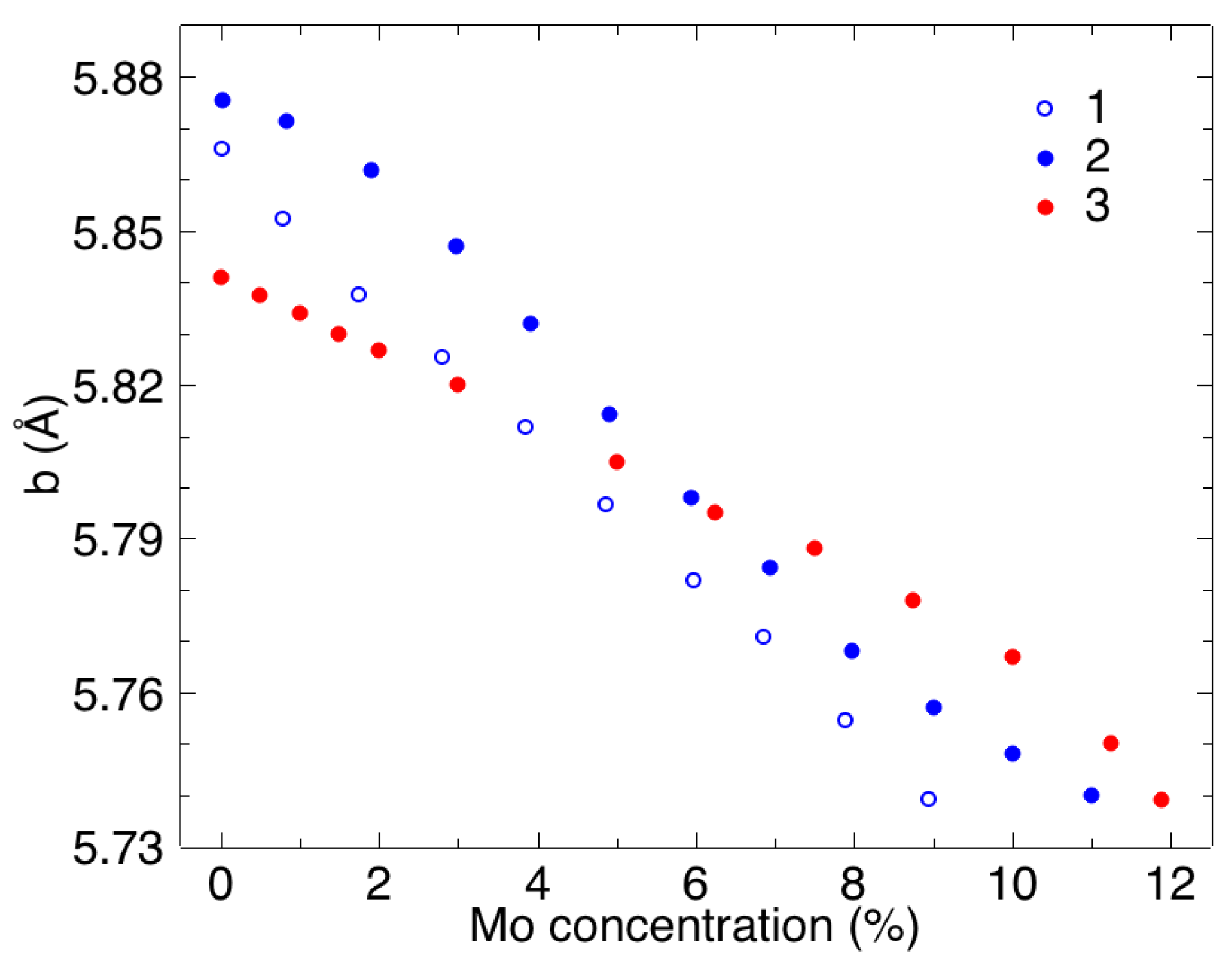
The monoclinic angle smoothly decreased with decreasing Mo concentration in the atomistic simulations as well as in the experiments [14,19,32]. The minimum Mo concentration for the α -phase was close to 5 at.% in the experiments (also in our calculations). For lower concentrations of molybdenum, the phase is called α , which can be considered as a lower limit of the α -phase with monoclinic angle approaching 90 degrees as in the orthorhombic structure of α -U [32]. Wherein, significant compression of the parameter b during α and α phase formation is observed [14,19], while the parameters a and c are changed slightly. The dependence of the parameter b on Mo concentration is shown in Figure 2. The figure contains the simulation results together with the experimental data [14,19].
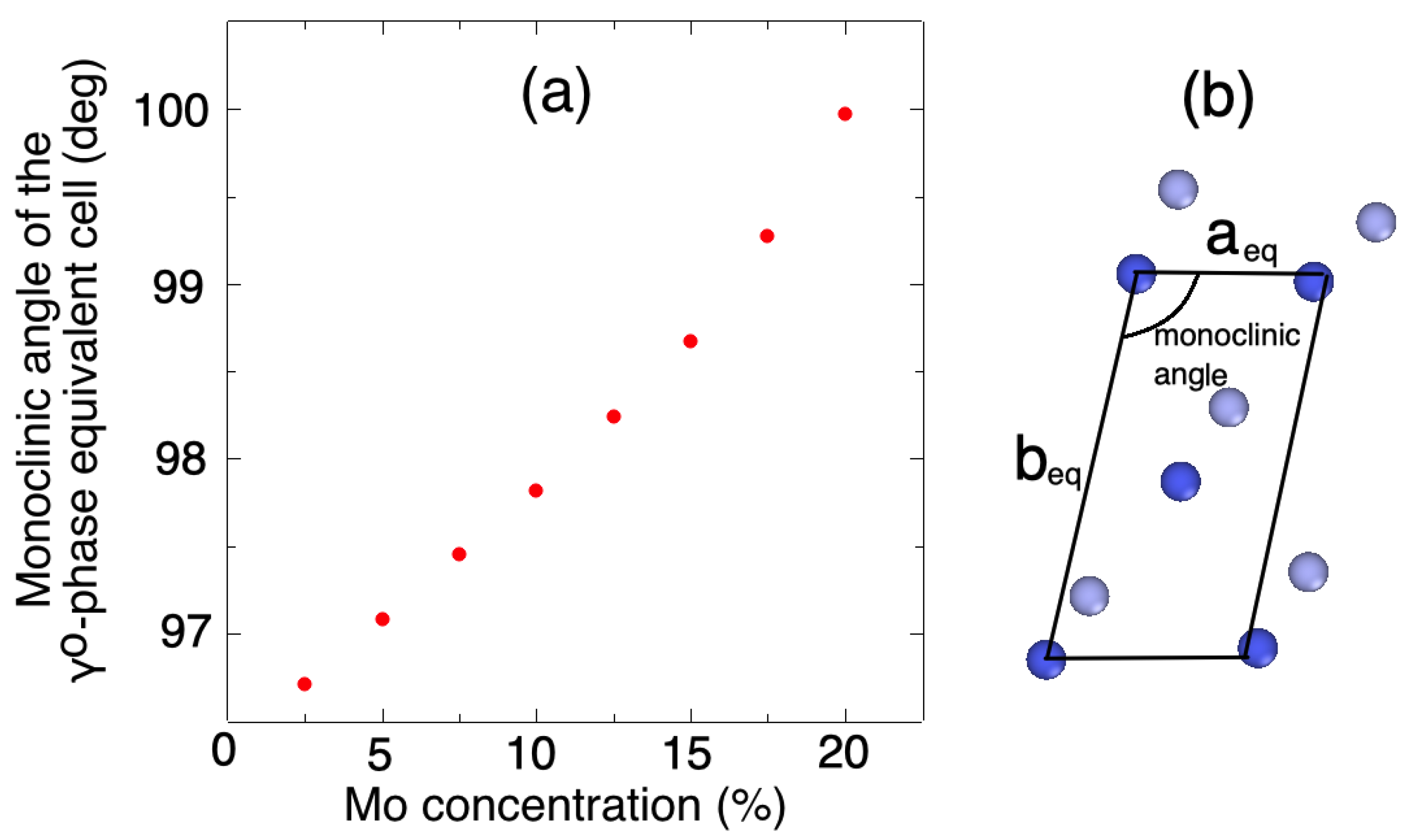
A decrease in parameter b with increasing doping takes place for uranium alloys with elements with a small atomic radius, such as Mo and Nb, due to the asymmetry of the α -like uranium crystal lattice [17]. The same effect is observed during heating of pure α -U—the thermal expansion coefficient in the <010> direction (along the b axis) is negative [33]. Thus, an increase in molybdenum concentration or in temperature facilitates the transition to a crystal structure with a higher level of symmetry. Moreover, it is considered that the criterion for the possibility of α α γ 0 transitions in the alloy is not the value of the parameter b itself but the ratio of the lattice parameters. A simple combination of parameters b / a may be chosen for the first approach since the main structural changes, lattice monocularization, occur in the plane a b . Thus, certain values of b / a corresponding to α α γ 0 transitions in U–Mo and U–Nb alloys can be estimated by averaging the experimental data [14,19,34] in the work [17]. It is noted that a value of 2.03 corresponds to the beginning of the lattice monoclinic distortion, and a value of 1.99 corresponds to a transition to the tetragonal γ 0 -phase. In our atomistic simulations these values were 2.04 and 2.00, respectively. Additionally, for the tetragonal γ 0 -phase lattice, one can introduce the monoclinic angle sides a e q and b e q of the equivalent cell as follows:
a e q = a g 2 ( c g / a g ) 2 + 2 , b e q = a g 2 9 ( c g / a g ) 2 + 2 , γ = 180 a r c s i n ( 4 2 ( c g / a g ) [ 9 ( c g / a g ) 2 + 2 ] [ ( c g / a g ) 2 + 2 ] ) ,
where a g and c g are γ 0 -phase lattice parameters. a e q and b e q axes correspond to the < 111 > γ 0 and < 11 ¯ 3 > γ 0 directions of the γ 0 -phase lattice, respectively.
Figure 3 shows the calculated values of monoclinic angles for various Mo concentrations. Variations of γ 0 -phase lattice parameters with composition were calculated in our previous work [23]. Those simulation results agreed well with the experimental data [21,35]. An increase in the c g / a g ratio leads to a decrease in the monoclinic angle with decreasing doping. Despite that tetragonal distortion does not decrease the monoclinic angle to the same values as for the α -phase, it reduces the necessary shift in atomic positions to those in the α -structure. Thus, for the U–Mo alloy with 11 at.% Mo (near the boundary of the α -phase area of stability), the change in monoclinic angle from 100 to 98 degrees reduces the angle difference between α - and γ 0 -phases by 30%. Moreover, density functional theory yielded a c g / a g of approximately 0.82 for pure uranium [36,37], which is close to the value of 0.815 required for monoclinic angle γ = 90 degrees.

3.2. Mechanical Properties of U–Mo Alloy

Not only lattice parameters of U–Mo alloys but also hardness strongly depends on its composition [17,38,39]. The hardness-composition curves show a maximum strength in the area of α -phase existence and maximum ductility near the α / γ 0 boundary. Moreover, the possibility of α γ 0 phase transition induced by deformation is discussed by Butcher and Hatt [39]. Additionally, γ 0 γ phase transition induced by deformation was observed in our previous simulations [40]. Such phase transition is most pronounced for U–xMo alloys with a c g / a g ratio approximately equal to 0.98 near the γ 0 / γ boundary. The deformation leads to atomic reorganization and tetragonal γ 0 → cubic γ -phase transition. A similar phenomenon was observed during deformation of the U–10 at.% Mo alloy with monoclinic angle equal to 92.3 degrees near the α / γ 0 boundary. We applied uniaxial deformation to the alloy model in the orthogonal simulation cell along the a axis (Figure 1b). A summary of the relevant data is presented in Figure 4.
The deformation led to an increase in lattice parameter a with parameter b remaining unchanged. Thus, a decrease in the c / a ratio took place. Formation of the γ 0 -phase occured under deformation ϵ x = 1.3% (Figure 5). One can notice that the c / a ratio was 2.0 in this moment, which corresponds to transition to the tetragonal γ 0 -phase as discussed above. However, the reverse deformation to the initial state took a different microscopic path. The disappearance of the γ 0 -phase happened differently from the initial value of deformation ϵ x = 0.5%. The appearance of a new phase layer reduced the elastic constants for the crystal orientation, such as the one shown in Figure 1b (i.e., the a-axis is directed along the x-direction). Thus, C 11 almost halved from 207 to 108 GPa, and C 22 was reduced by 40% from the initial value of 100 GPa after deformation ϵ x = 3%.
In order to study the structure of alloys, we used pair distribution functions G ( r ) , which can be easily calculated from the molecular dynamics simulations. Figure 6 shows the calculated pair distribution functions for different alloy structures: α -phase and γ d e f o r m e d 0 -phase appeared under deformation and non-deformed γ 0 -phase. G U U ( r ) of the γ d e f o r m e d 0 -phase coincided well with the G U U ( r ) of the “stable” γ 0 -phase with the same Mo content. Moreover, the G ( r ) first peak was split into two peaks ( r 2.7 Å and r 3.3 Å). For an ideal bct lattice, the first G ( r ) maximum corresponds to the distance r 3.0 Å (the distance from the central atom to the atoms located at the vertices of the basic cell). This splitting was associated with a displacement of central atoms in the basic cell to the [ 001 ] direction [23,40] and exactly matched peak positions in the α -phase. Thereby, not only did the tetragonal distortion of the γ 0 -phase simplify the α γ 0 phase transition, but it also displaced the central atom in the basic cell to the [ 001 ] direction. Conversely, the local arrangement of molybdenum atoms both in α - and γ 0 -phases was closer to a cubic lattice. Thus, molybdenum atoms can be considered as the stabilization centers of the bcc lattice.
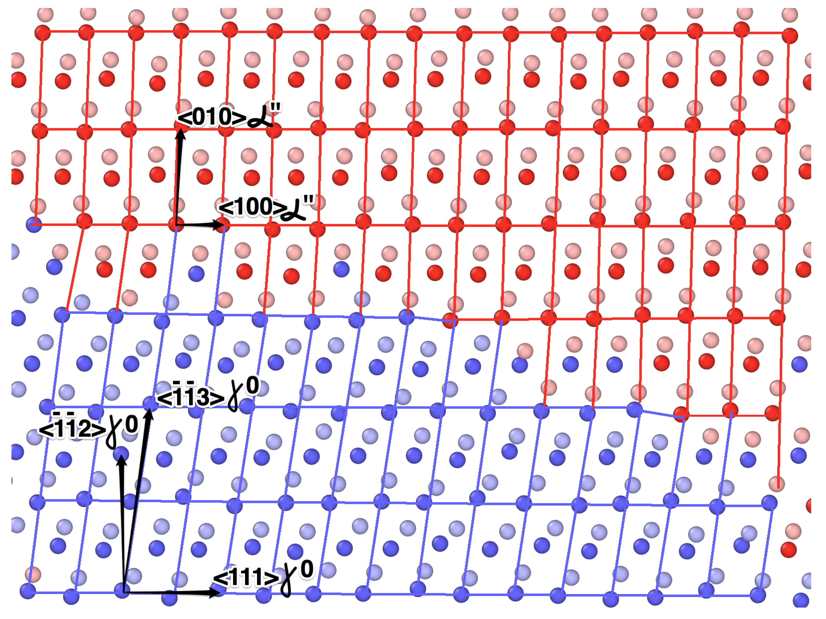
The formed boundary between the α -phase and γ 0 -phase is shown in Figure 7. During deformation, the following relationship between the α -phase and γ 0 -phase orientations exists:
< 010 > α < 11 ¯ 3 > γ 0 , < 100 > α < 111 > γ 0 , < 001 > α < 1 1 ¯ 0 > γ 0 .
where the < 010 > α direction is situated between < 11 ¯ 3 > γ 0 and < 11 ¯ 2 > γ 0 directions. Nevertheless, monoclinic cell distortion alone is not enough. Inhomogeneous deformation—a shift of type z = 0.5 c α layers with fixed z = 0 type—is necessary. It should be noted that there was movement of the atoms in the plane z = 0.5 c α in the basic cell of α -phase along the < 100 > α axis from their positions in the α -phase, as reported in [32]. Herewith, this movement increased with increasing doping. In our atomistic simulation, the displacement along the < 100 > α axis had a magnitude of approximately 0.03 a α for U–10 at.% Mo alloy at the room temperature, which is less than the value 0.07 a α obtained from XRD analysis [32]. Despite small order of magnitude, it may play a role in reducing the necessary atomic rearrangements during α γ 0 phase transition.

4. Discussion

The structural properties of orthorhombic, monoclinic, and body-centered tetragonal phases of U–Mo alloys were examined using molecular dynamics simulations. The influence of Mo concentration on the structure of these phases have been investigated. Our simulations showed that doping of uranium with molybdenum leads to changes in the monoclinic angle and lattice parameters and makes structure more like the γ 0 -phase. The calculation results are in good agreement with experimental data. Moreover, molybdenum atoms can be considered as the stabilization centers of the bcc lattice not only in the γ 0 -phase but also in the α -phase. In turn, tetragonal distortion of the γ 0 -phase lattice with displacement of a central atom in the basic cell along <001> direction makes it more like the α -phase. Both of these effects reduce the necessary shift in atomic positions for α γ 0 -phase transition. Additionally, it is shown that α γ 0 phase transition induced by deformation took place in U–10 at.% Mo alloy. The relationship between the atomic position of the monoclinic and tetragonal phases during such transition is discussed. In the experiments, the U–Mo alloy had an inhomogeneous dendrite structure with Mo-rich and Mo-lean regions. Thus, the influence of Mo concentration on the U–Mo phase stability is important in understanding homogenization of lamellar two-phase mixtures of the orthorhombic α -U and the tetragonal γ -phase U 2 M o .

Author Contributions

Conceptualization; methodology; validation; formal analysis; investigation; resources; writing—original draft preparation; writing—review and editing; visualization, L.K. and I.G. All authors have read and agree to the published version of the manuscript.

Funding

This research was funded by the Russian Science Foundation grant number 19-79-00348.

Acknowledgments

The calculations were carried out on the computer clusters MVS-10P and MVS-10Q of the Joint Supercomputer Center of RAS.

Conflicts of Interest

The authors declare no conflicts of interest.

References

  1. Kalashnikov, V.; Titova, V.; Sergeev, G.I.; Samoilov, A. Uranium-molybdenum alloys in reactor construction. At. Energy 1959, 5, 1315–1325. [Google Scholar] [CrossRef]
  2. Landa, A.; Söderlind, P.; Turchi, P. Density-functional study of U–Mo and U–Zr alloys. J. Nucl. Mater. 2011, 414, 132–137. [Google Scholar] [CrossRef] [Green Version]
  3. Kim, Y.S.; Hofman, G. Fission product induced swelling of U–Mo alloy fuel. J. Nucl. Mater. 2011, 419, 291–301. [Google Scholar] [CrossRef]
  4. Vatulin, A.; Morozov, A.; Suprun, V.; Petrov, Y.I.; Trifonov, Y.I. Radiation resistance of high-density uranium—molybdenum dispersion fuel for nuclear research reactors. At. Energy 2006, 100, 37–46. [Google Scholar] [CrossRef]
  5. Rest, J.; Kim, Y.S.; Hofman, G.; Meyer, M.; Hayes, S. U-Mo Fuels Handbook; Argonne Natoinal Laboratory: Lemont, IL, USA, 2009. [Google Scholar]
  6. Neogy, S.; Saify, M.; Jha, S.; Srivastava, D.; Dey, G. Ageing characteristics of the metastable gamma phase in U–9 wt.% Mo alloy: Experimental observations and thermodynamic validation. Philos. Mag. 2015, 95, 2866–2884. [Google Scholar] [CrossRef]
  7. Xu, Z.; Joshi, V.; Hu, S.; Paxton, D.; Lavender, C.; Burkes, D. Modeling the homogenization kinetics of as-cast U-10wt% Mo alloys. J. Nucl. Mater. 2016, 471, 154–164. [Google Scholar] [CrossRef] [Green Version]
  8. Konobeevskii, S.; Pravdyuk, N.; Dubrovin, K.; Levitskii, B.; Panteleev, L.; Golianov, V. An investigation of structural changes caused by neutron irradiation of a uranium molybdenum alloy. J. Nucl. Energy Part B 1959, 9, 75–89. [Google Scholar]
  9. Hofman, G.L.; Meyer, M.K.; Ray, A.E. Design of high density gamma-phase uranium alloys for LEU dispersion fuel applications. In Proceedings of the International Reduced Enrichment for Research and Test Reactors Conference, Sao Paulo, Brazil, 18–20 October 1998. [Google Scholar]
  10. Hengstler, R.; Beck, L.; Breitkreutz, H.; Jarousse, C.; Jungwirth, R.; Petry, W.; Schmid, W.; Schneider, J.; Wieschalla, N. Physical properties of monolithic U8wt.%–Mo. J. Nucl. Mater. 2010, 402, 74–80. [Google Scholar] [CrossRef]
  11. Joshi, V.V.; Nyberg, E.A.; Lavender, C.A.; Paxton, D.; Burkes, D.E. Thermomechanical process optimization of U-10wt% Mo – Part 2: The effect of homogenization on the mechanical properties and microstructure. J. Nucl. Mater. 2015, 465, 710–718. [Google Scholar] [CrossRef] [Green Version]
  12. Neogy, S.; Saify, M.; Jha, S.; Srivastava, D.; Hussain, M.; Dey, G.; Singh, R. Microstructural study of gamma phase stability in U–9wt.% Mo alloy. J. Nucl. Mater. 2012, 422, 77–85. [Google Scholar] [CrossRef]
  13. Pedrosa, T.A.; dos Santos, A.M.M.; Lameiras, F.S.; Cetlin, P.R.; Ferraz, W.B. Phase transitions during artificial ageing of segregated as-cast U–Mo alloys. J. Nucl. Mater. 2015, 457, 100–117. [Google Scholar] [CrossRef]
  14. Tangri, K.; Williams, G. Metastable phases in the uranium molybdenum system and their origin. J. Nucl. Mater. 1961, 4, 226–233. [Google Scholar] [CrossRef]
  15. Yakel, H.L. Crystal structures of transition phases formed in U–16.60 at.%Nb–5.64 at.%Zr alloys. J. Nucl. Mater. 1969, 33, 286–295. [Google Scholar] [CrossRef]
  16. Howlett, B. A study of the shear transformations from the gamma-phase in uranium-molybdenum alloys containing 6.0–12.5 at% molybdenum. J. Nucl. Mater. 1970, 35, 278–292. [Google Scholar] [CrossRef]
  17. Ivanov, O.S.; Badaeva, T.A.; Sofronova, R.M.; Kishenevskiy, V.B.; Kushnir, N.P. Phase Diagrams and Phase Transitions in Uranium Alloys; Nauka: Moscow, Russia, 1972; p. 254. [Google Scholar]
  18. Chebotarev, N.T.; Utkina, O.N. Crystal structure of γS phase in U-Mo, U-Re and U-Nb alloys. At. Energy 1980, 48, 76–80. [Google Scholar] [CrossRef]
  19. Lehmann, M.J. Phases monocliniques dans les alliages uranium-molybdene. J. Nucl. Mater. 1961, 4, 218–225. [Google Scholar] [CrossRef]
  20. Vandermeer, R.; Ogle, J.; Northcutt, W. A phenomenological study of the shape memory effect in polycrystalline uranium-niobium alloys. Metall. Mater. Trans. A 1981, 12, 733–741. [Google Scholar] [CrossRef]
  21. Tkach, I.; Kim-Ngan, N.T.; Mašková, S.; Dzevenko, M.; Havela, L.; Warren, A.; Stitt, C.; Scott, T. Characterization of cubic γ-phase uranium molybdenum alloys synthesized by ultrafast cooling. J. Alloys Compd. 2012, 534, 101–109. [Google Scholar] [CrossRef]
  22. Sagaradze, V.V.; Zuev, Y.N.; Bondarchuk, S.V.; Svyatov, I.L.; Shestakov, A.E.; Pecherkina, N.L.; Kabanova, I.G.; Klyukin, M.F. Structural Heredity in the U–6Nb Alloy and Conditions for Its Elimination. Phys. Met. Metallogr. 2013, 114, 299–307. [Google Scholar] [CrossRef]
  23. Starikov, S.; Kolotova, L.; Kuksin, A.Y.; Smirnova, D.; Tseplyaev, V. Atomistic simulation of cubic and tetragonal phases of U-Mo alloy: Structure and thermodynamic properties. J. Nucl. Mater. 2018, 499, 451–463. [Google Scholar] [CrossRef]
  24. Beeler, B.; Deo, C.; Baskes, M.; Okuniewski, M. Atomistic properties of γ uranium. J. Phys. Condens. Matter 2012, 24, 075401. [Google Scholar] [CrossRef] [PubMed]
  25. Fernández, J.R.; Pascuet, M. On the accurate description of uranium metallic phases: A MEAM interatomic potential approach. Model. Simul. Mater. Sci. Eng. 2014, 22, 055019. [Google Scholar] [CrossRef]
  26. Moore, A.; Deo, C.; Baskes, M.; Okuniewski, M.; McDowell, D. Understanding the uncertainty of interatomic potentials’ parameters and formalism. Comput. Mater. Sci. 2017, 126, 308–320. [Google Scholar] [CrossRef] [Green Version]
  27. Ercolessi, F.; Adams, J.B. Interatomic potentials from first-principles calculations: The force-matching method. Europhys. Lett 1994, 26, 583. [Google Scholar] [CrossRef] [Green Version]
  28. Brommer, P.; Gahler, F. Potfit: Effective potentials from ab initio data. Modell. Simul. Mater. Sci. Eng. 2007, 15, 295. [Google Scholar] [CrossRef] [Green Version]
  29. Plimpton, S.J. Fast parallel algorithms for short-range molecular dynamics. J. Comp. Phys. 1995, 117, 1. [Google Scholar] [CrossRef] [Green Version]
  30. Stukowski, A. Visualization and analysis of atomistic simulation data with OVITO—The Open Visualization Tool. Model. Simul. Mater. Sci. Eng. 2009, 18, 015012. [Google Scholar] [CrossRef]
  31. Lehmann, J.; Hills, R. Proposed nomenclature for phases in uranium alloys. J. Nucl. Mater. 1960, 2. [Google Scholar] [CrossRef]
  32. Stewart, D.; Williams, G. The structure and occurrence of the metastable monoclinic phase, α b, in uranium-molybdenum alloys. J. Nucl. Mater. 1966, 20, 262–268. [Google Scholar] [CrossRef]
  33. Kaufmann, A.R. Nuclear Reactor Fuel Elements: Metallurgy and Fabrication; Interscience Publishers: Geneva, Switzerland, 1962. [Google Scholar]
  34. Tangri, K.; Chaudhuri, D. Metastable phases in uranium alloys with high solute solubility in the BCC gamma phase. Part I—the system U-Nb. J. Nucl. Mater. 1965, 15, 278–287. [Google Scholar] [CrossRef]
  35. Sinha, V.; Hegde, P.; Prasad, G.; Dey, G.; Kamath, H. Phase transformation of metastable cubic γ-phase in U–Mo alloys. J. Alloys Compd. 2010, 506, 253–262. [Google Scholar] [CrossRef]
  36. Hood, R.Q.; Yang, L.; Moriarty, J.A. Quantum molecular dynamics simulations of uranium at high pressure and temperature. Phys. Rev. B 2008, 78, 024116. [Google Scholar] [CrossRef] [Green Version]
  37. Soderlind, P. Theory of the crystal structures of cerium and the light actinides. Adv. Phys. 1998, 47, 959–998. [Google Scholar] [CrossRef]
  38. Hills, R.; Butcher, B.; Howlett, B. The mechanical properties of quenched uranium-molybdenum alloys: Part I: Tensile tests on polycbystalline specimens. J. Nucl. Mater. 1964, 11, 149–162. [Google Scholar] [CrossRef]
  39. Butcher, B.; Hatt, B. The mechanical properties of quenched uranium-molybdenum alloys: Part II: A preliminary survey of the deformation mechanisms. J. Nucl. Mater. 1964, 11, 163–182. [Google Scholar] [CrossRef]
  40. Starikov, S.; Kolotova, L. Features of cubic and tetragonal structures of U–Mo alloys: Atomistic simulation. Scr. Mater. 2016, 113, 27–30. [Google Scholar] [CrossRef]
Figure 1. (a) The monoclinic angle of the α -phase at room temperature (for various Mo concentrations): 1—values measured in work [32]; 2—calculated data from this work. The inset shows the monoclinic angle of equivalent cell of the γ 0 -phase at room temperature dependent on the Mo concentration. (b) Projection of atomic positions in the α -phase unit cell onto its [001] plane. Red atoms correspond to the z = 0 plane and pink atoms to the z = 0.5 c plane.
Crystals 10 00515 g001
Figure 2. The lattice parameter b of α -phase and α -phase at room temperature (for various Mo concentrations): 1—values measured in work [14]; 2—values measured in work [19]; 3—calculated data from this work.
Crystals 10 00515 g002
Figure 3. (a) The monoclinic angle of an equivalent cell of γ 0 -phase at room temperature (for various Mo concentrations). (b) Projection of atomic positions in the γ 0 -phase equivalent unit cell onto its [ 1 1 ¯ 0 ] plane. Blue atoms correspond to the z = 0 plane and light blue atoms to the z = 0.5 c e q plane.
Crystals 10 00515 g003
Figure 4. (a) Calculation results for uniaxial deformation of U–10 at.% Mo alloy at room temperature. Extension takes place along the x direction. The dependencies of pressure components on deformation: solid lines—initial extension; dashed lines—inverse deformation to initial sizes of the calculation cell. (b) γ 0 -phase fraction in % during deformation.
Crystals 10 00515 g004
Figure 5. Fragment of the calculation cell for the deformation ϵ x = 1.3%, final state ϵ x = 3%, and deformation ϵ x = 0.5% during reverse compression (two atomic planes are shown): red atoms correspond to the α -phase and blue atoms to the γ 0 -phase.
Crystals 10 00515 g005
Figure 6. Calculated pair distribution functions for different U–10 at.% Mo alloy structures: (a) Three dependencies of G U U ( r ) at room temperature: α -phase and γ d e f o r m e d 0 -phase appeared under deformation and non-deformed γ 0 -phase. (b) Two dependencies of G M o M o ( r ) at room temperature: α -phase and γ d e f o r m e d 0 -phase appeared under deformation.
Crystals 10 00515 g006
Figure 7. The formed boundary between two phases for the deformation ϵ x = 1.3% (atoms in the z = 0 plane are shown in dark color and atoms in the z = 0.5 c α plane in light color): red atoms correspond to the α -phase and blue atoms to the γ 0 -phase.
Crystals 10 00515 g007
Table 1. Computed energies (in eV/atom) of the α -phase and γ 0 -phase (for various Mo concentrations) at T = 0 K. All values are given with respect to the energy of the α -phase.
5 at.% of Mo7.5 at.% of Mo10 at.% of Mo12.5 at.% of Mo
α -phase00.0010.0030.005
γ 0 -phase0.0150.010.0090.005