Implications of Metamaterial on Ultra-Wide Band Microstrip Antenna Performance


Abstract
1. Introduction
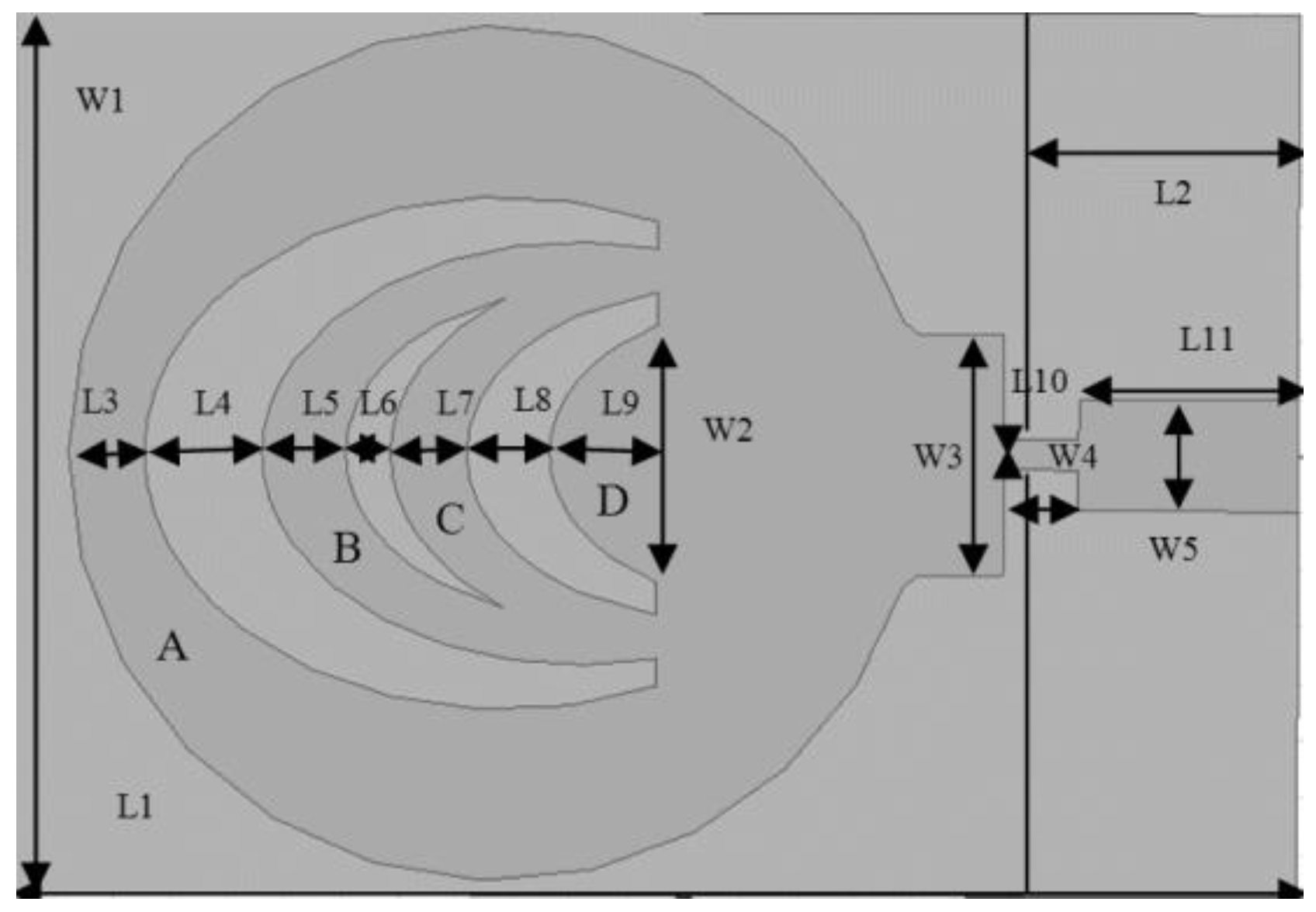
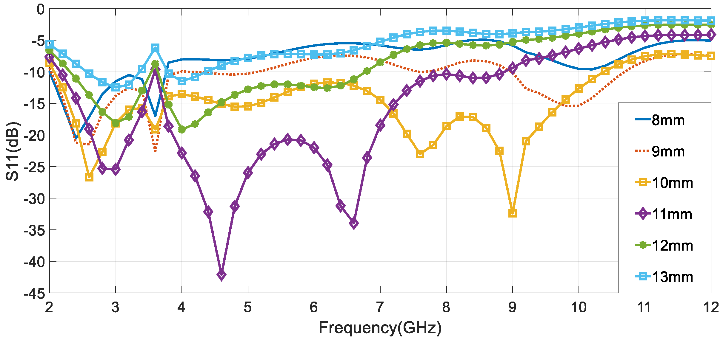
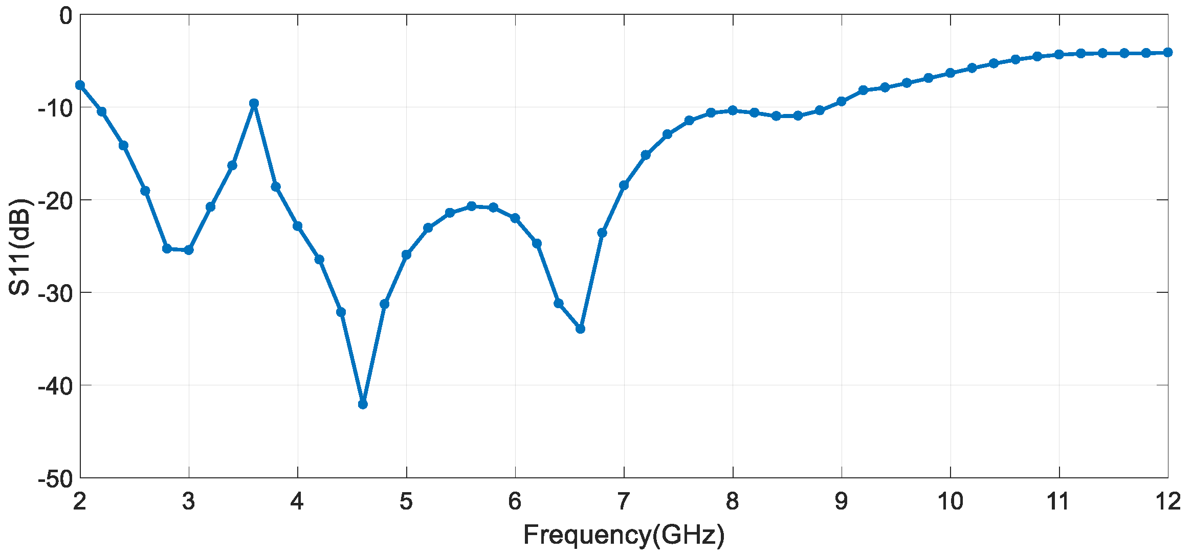
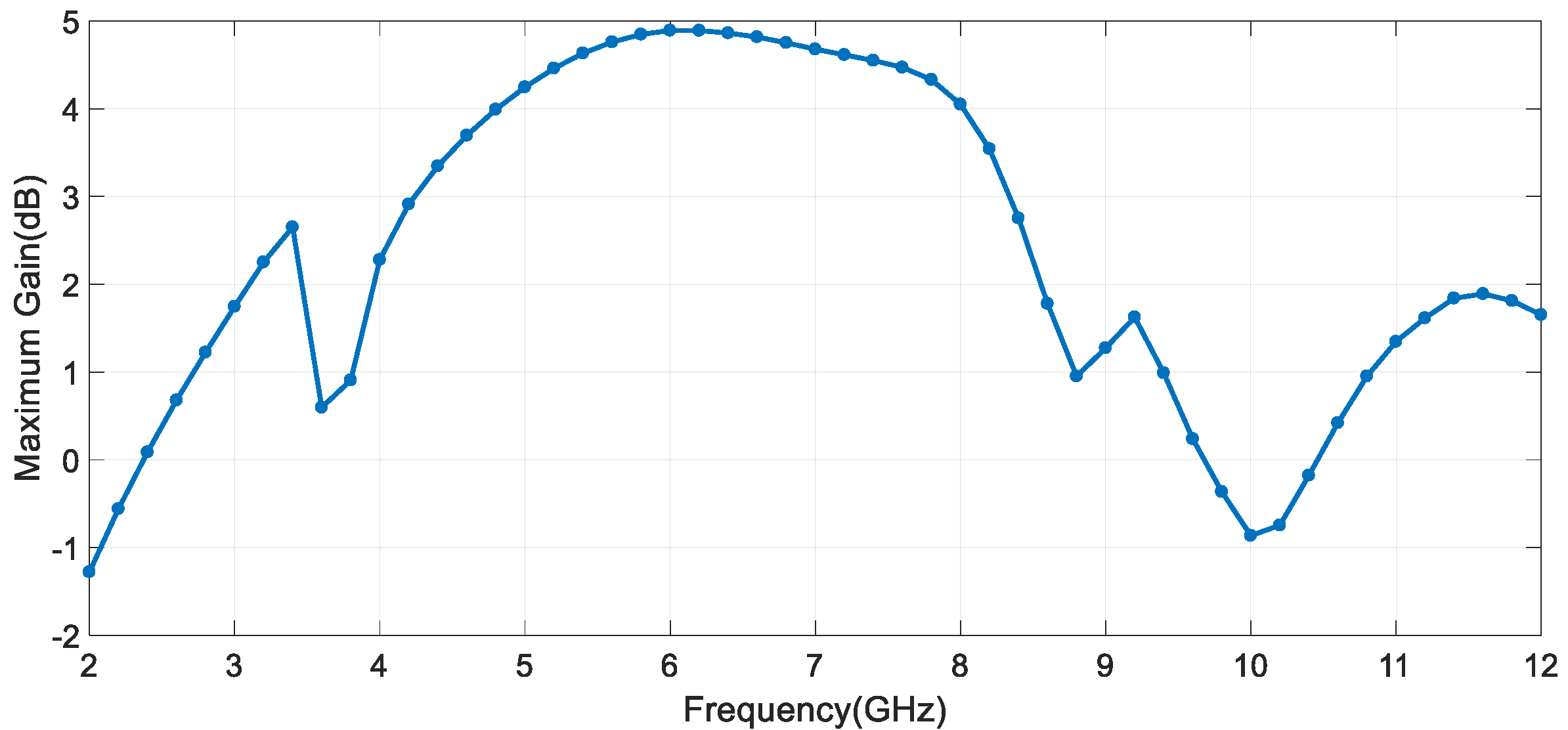
2. Antenna Design
3. Metamaterials Design
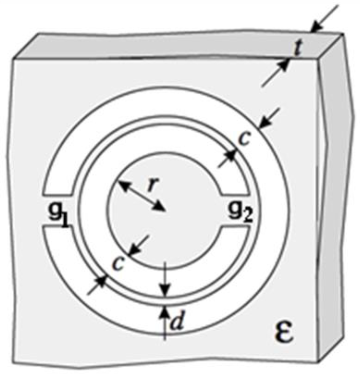
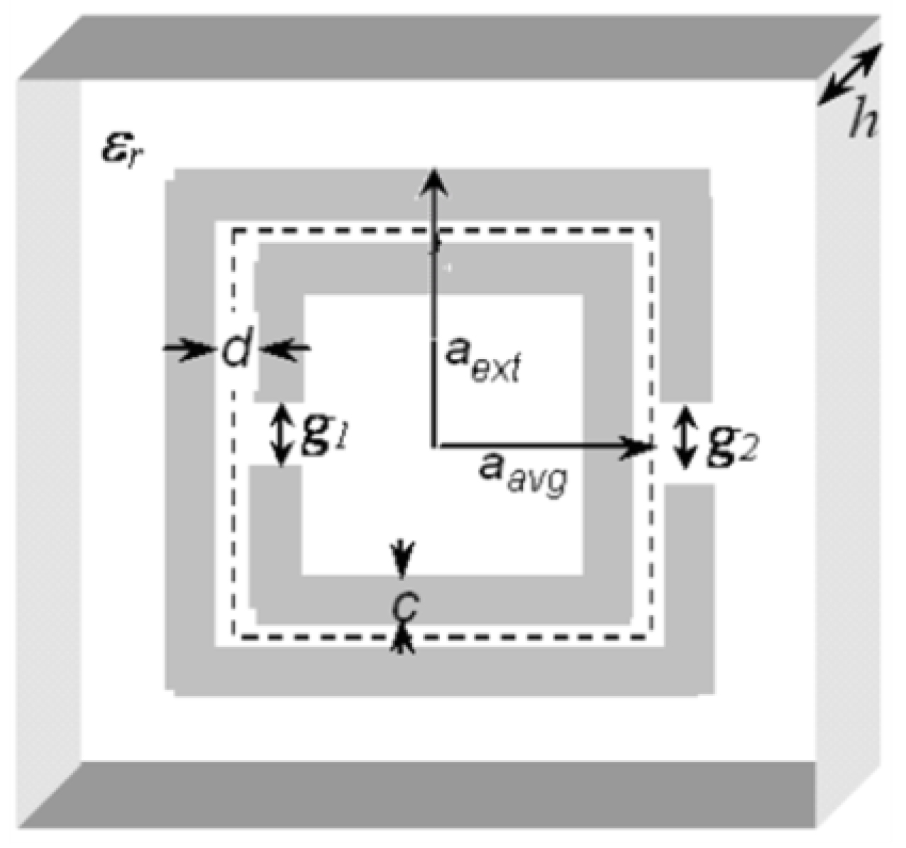
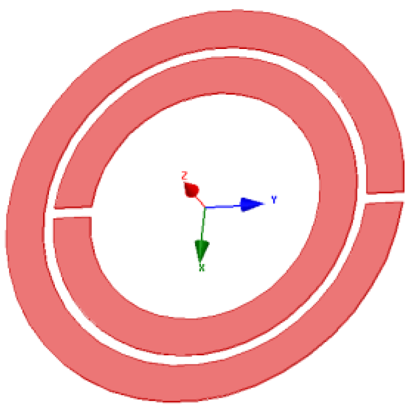
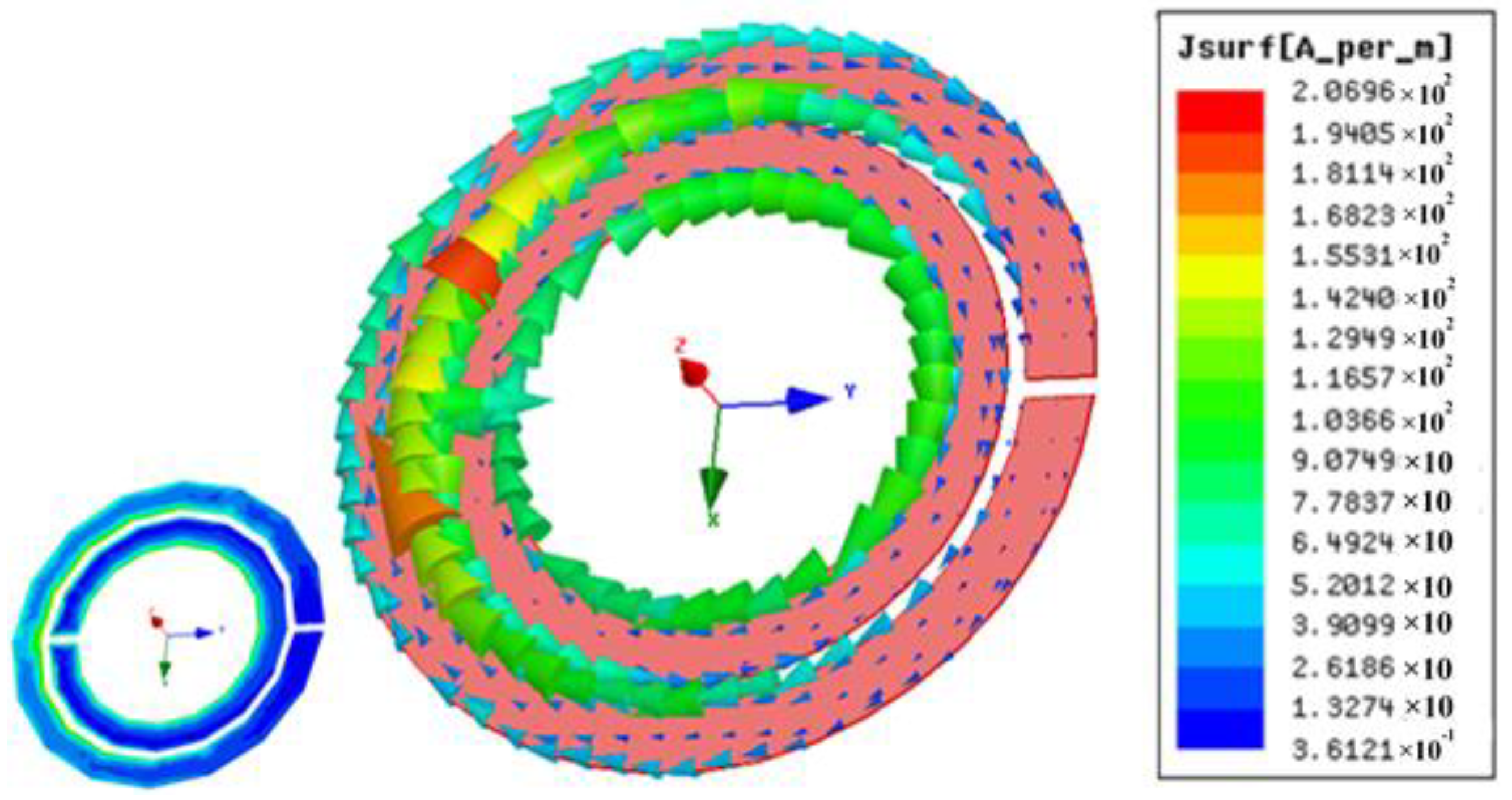
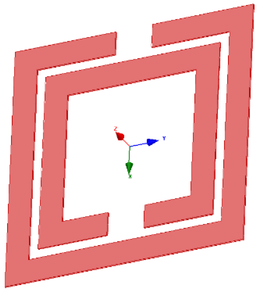
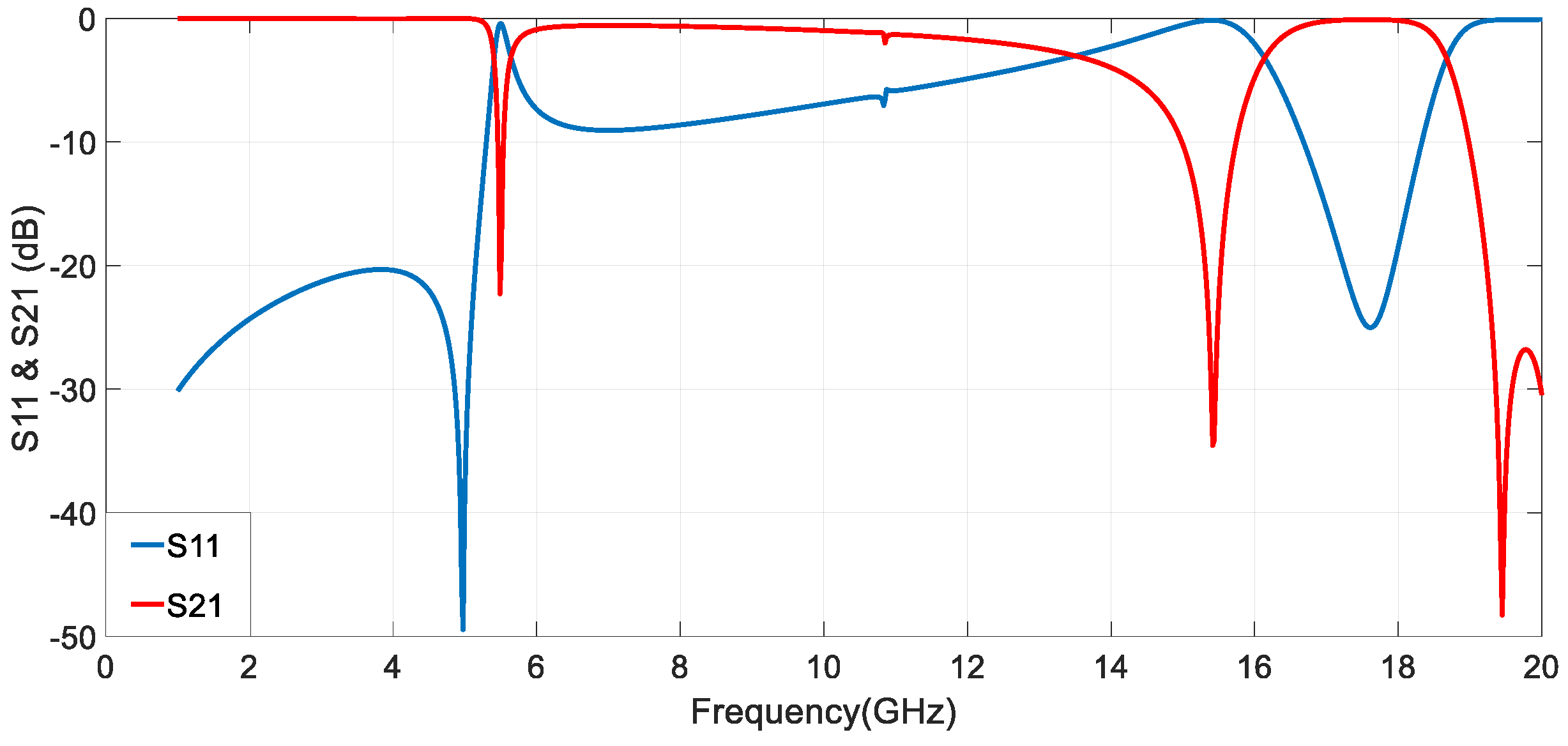
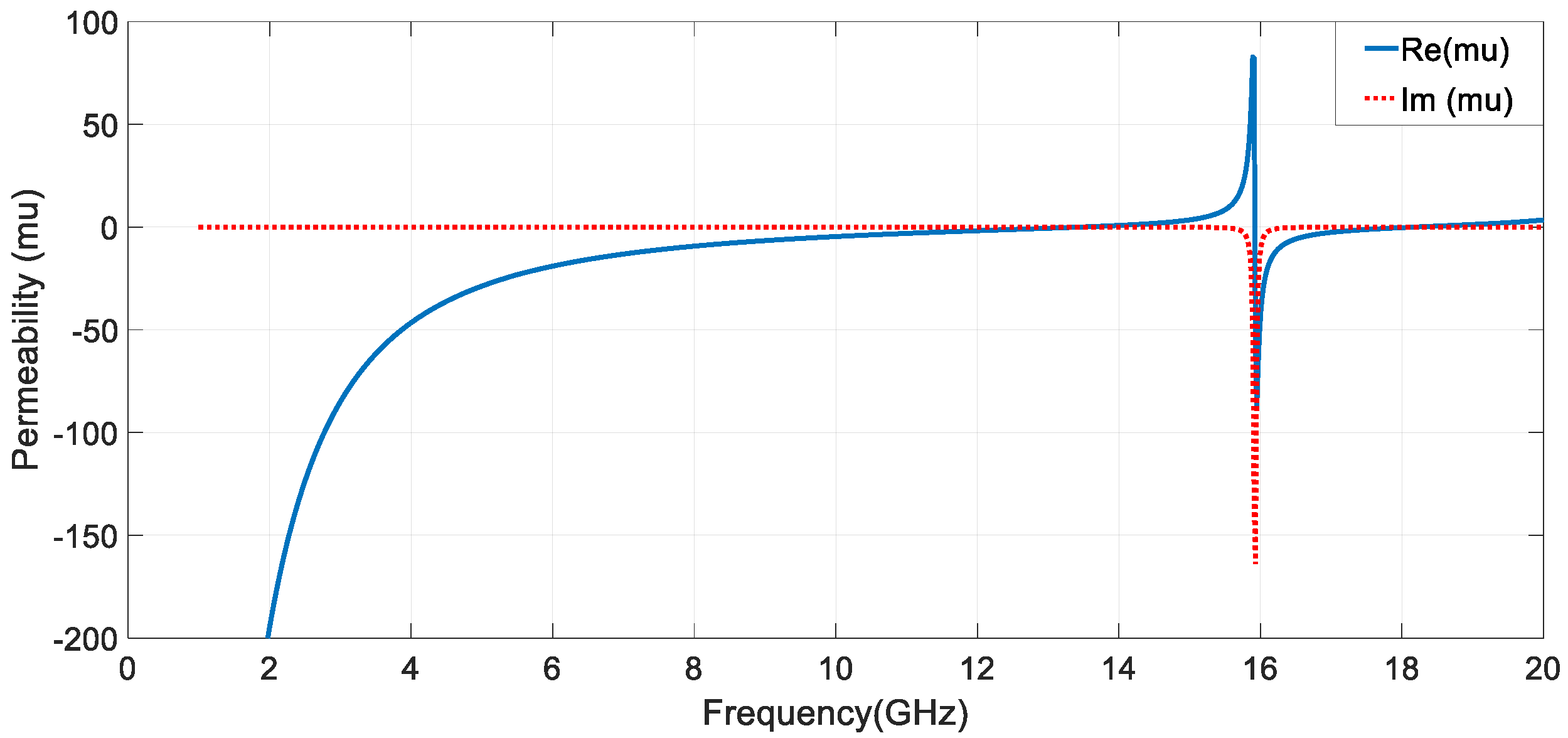
3.1. Circular SRR (C-SRR) and Square SRR (S-SRR) Design
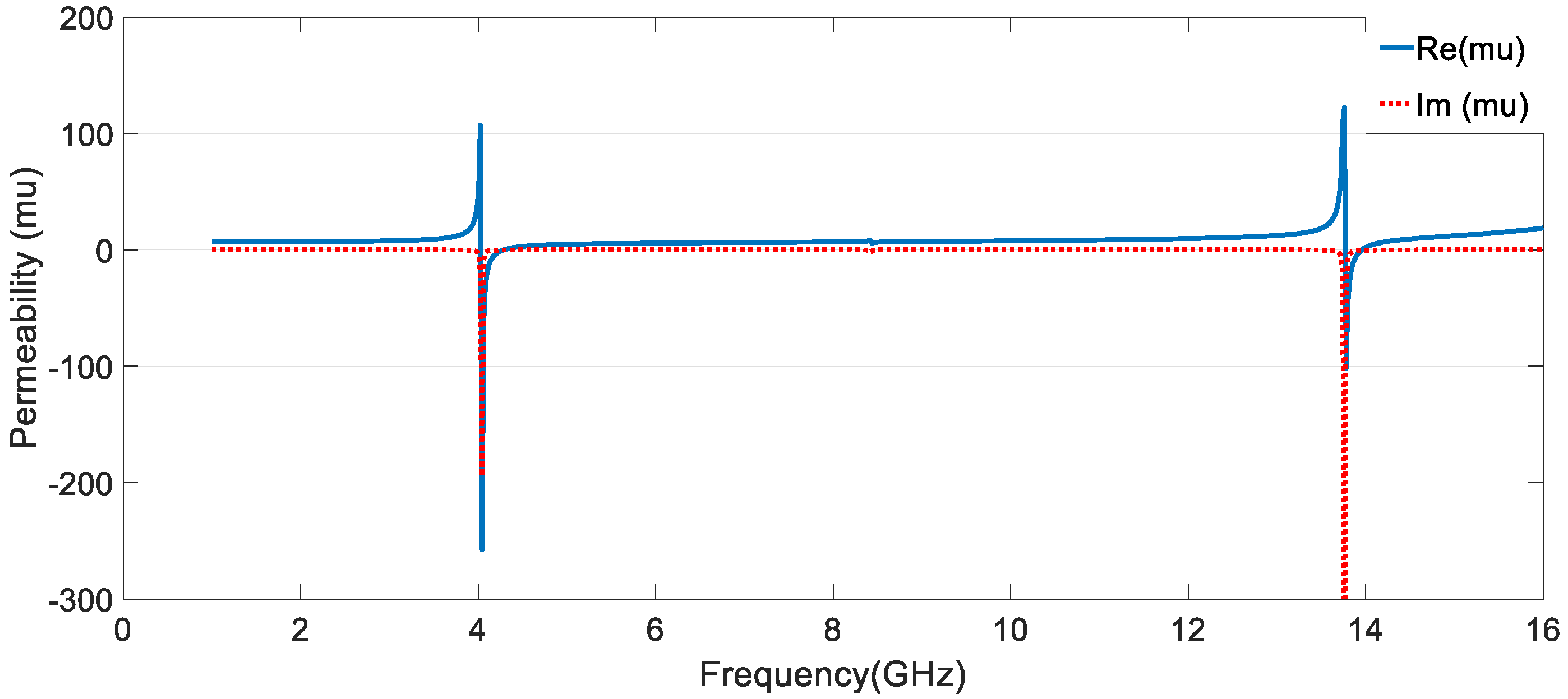
3.2. Circular and Square SRR Design Analysis
4. Antennas Implemented with Metamaterials
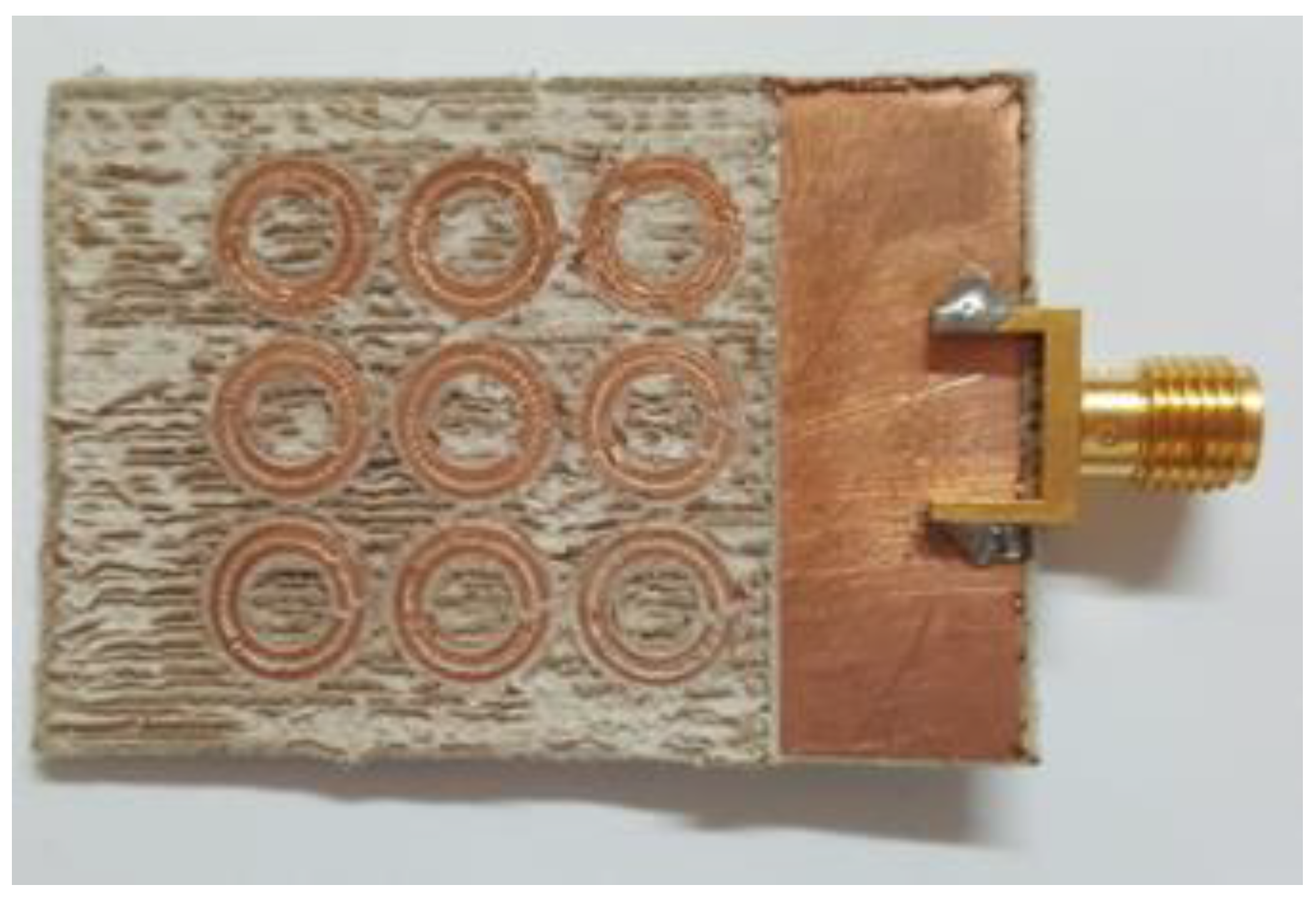
4.1. Implementation of Circular-SRR
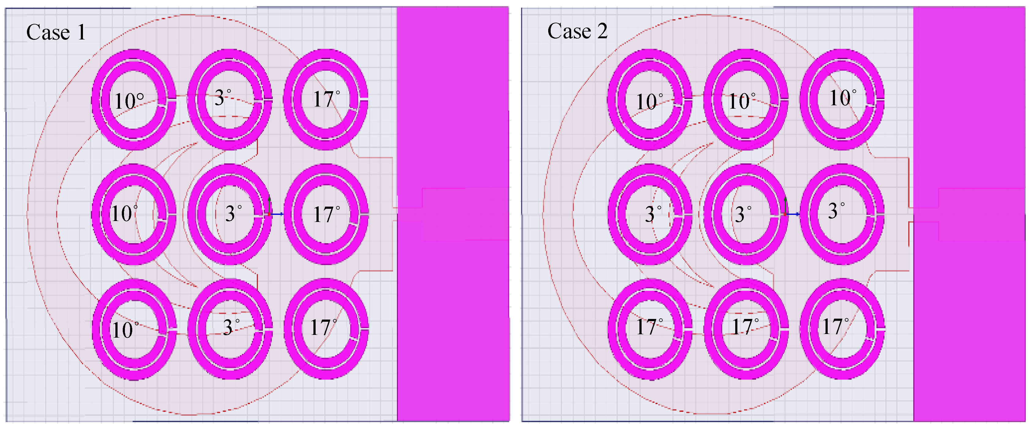
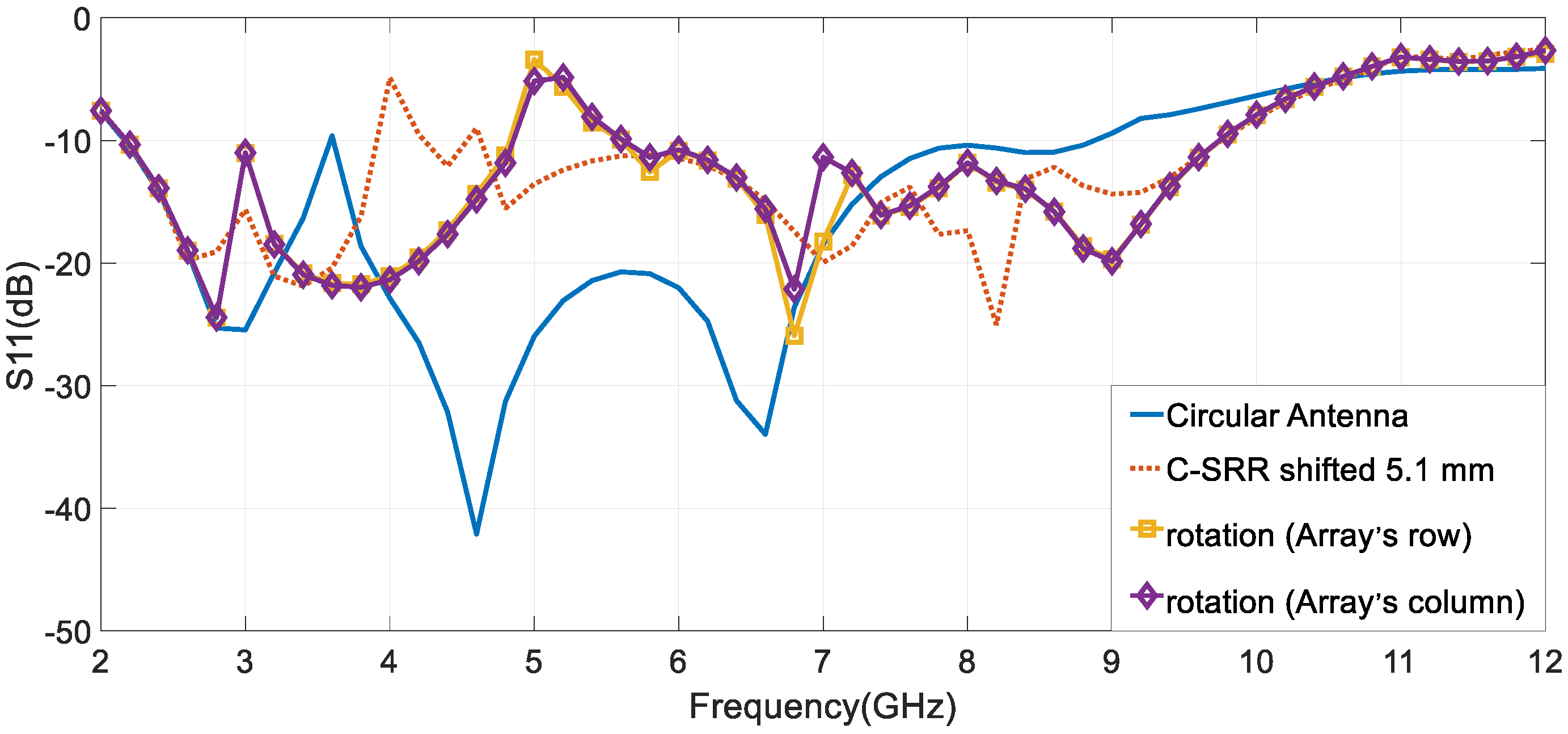
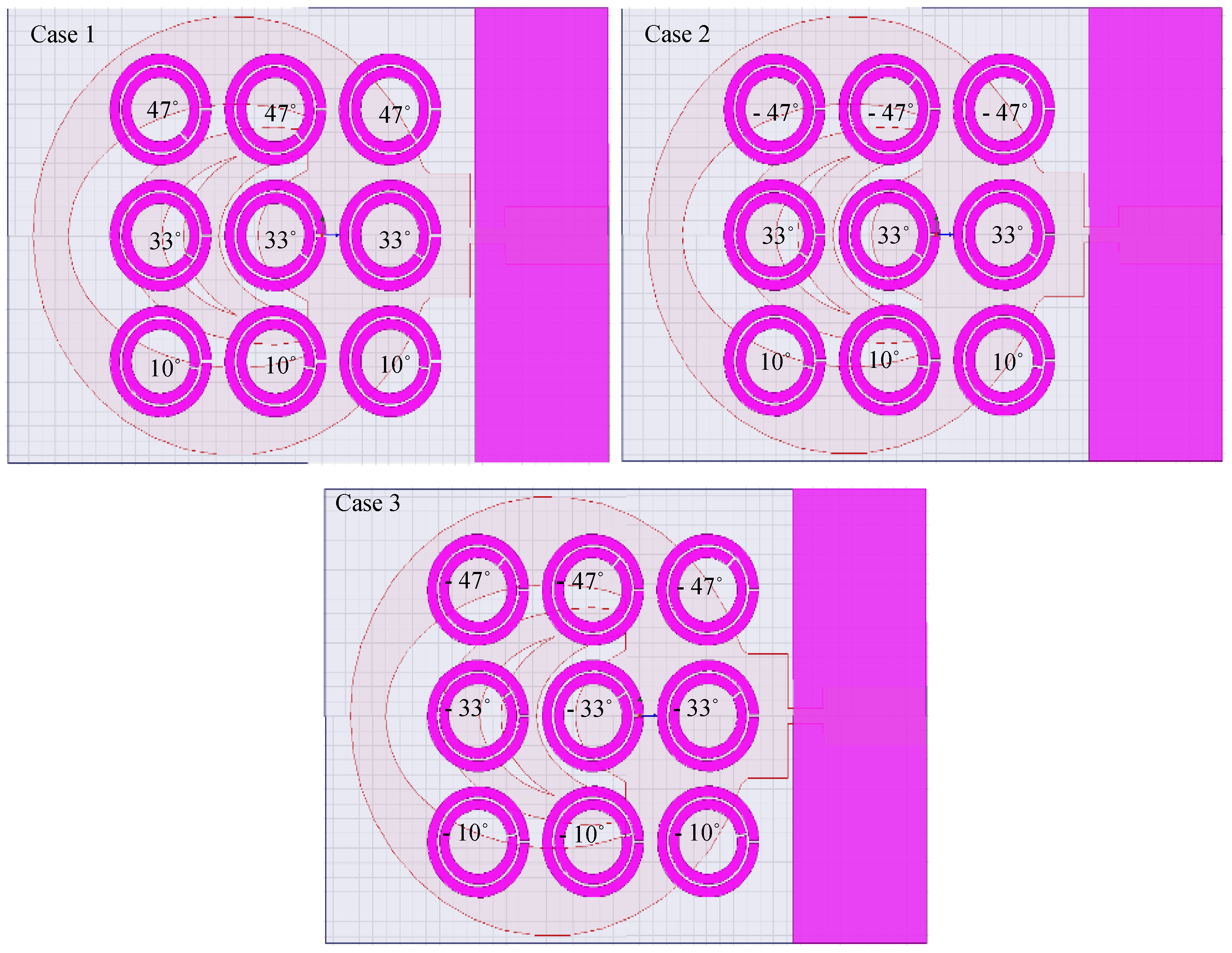
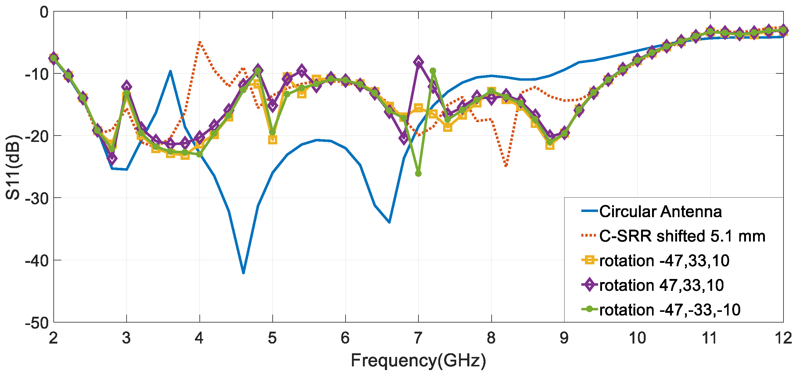
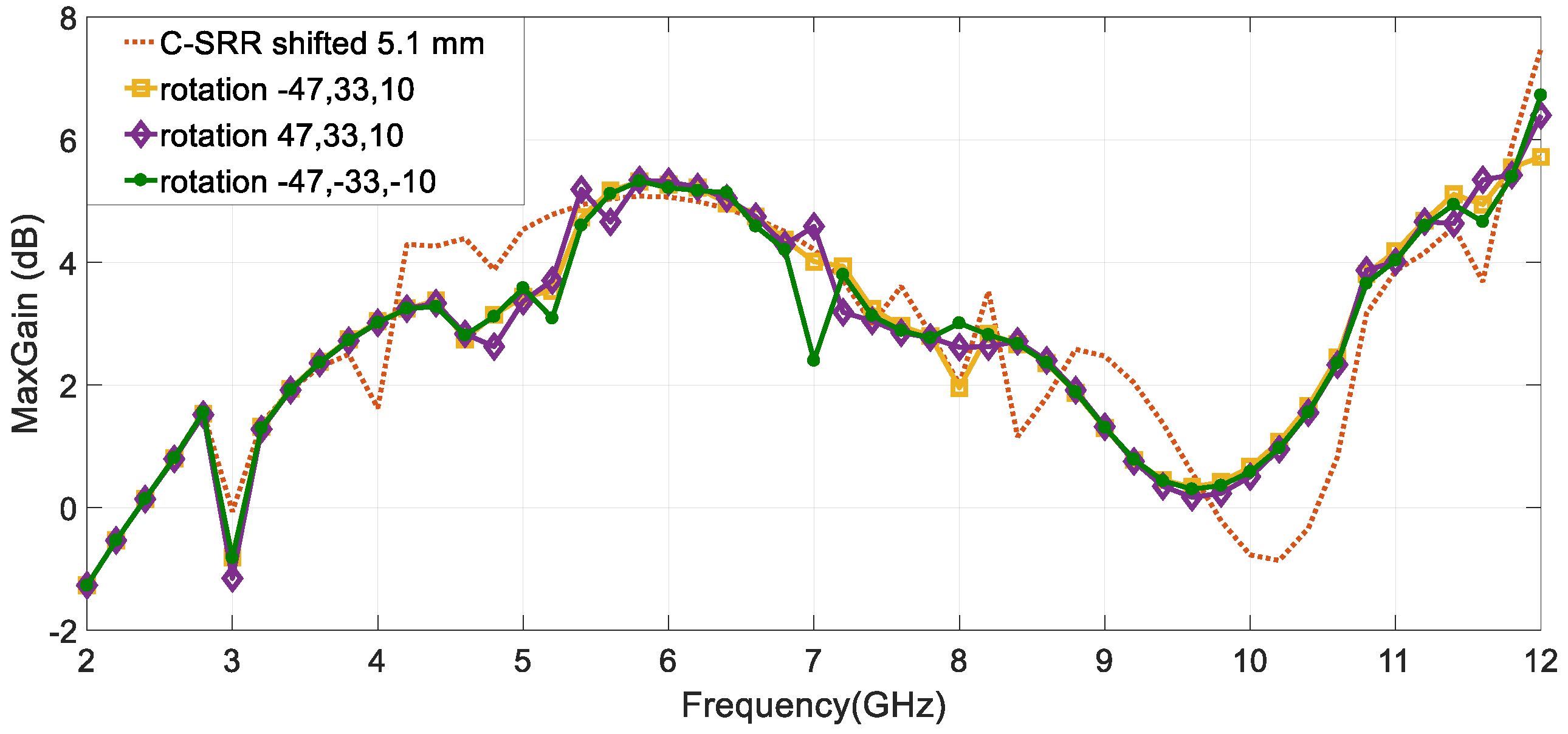
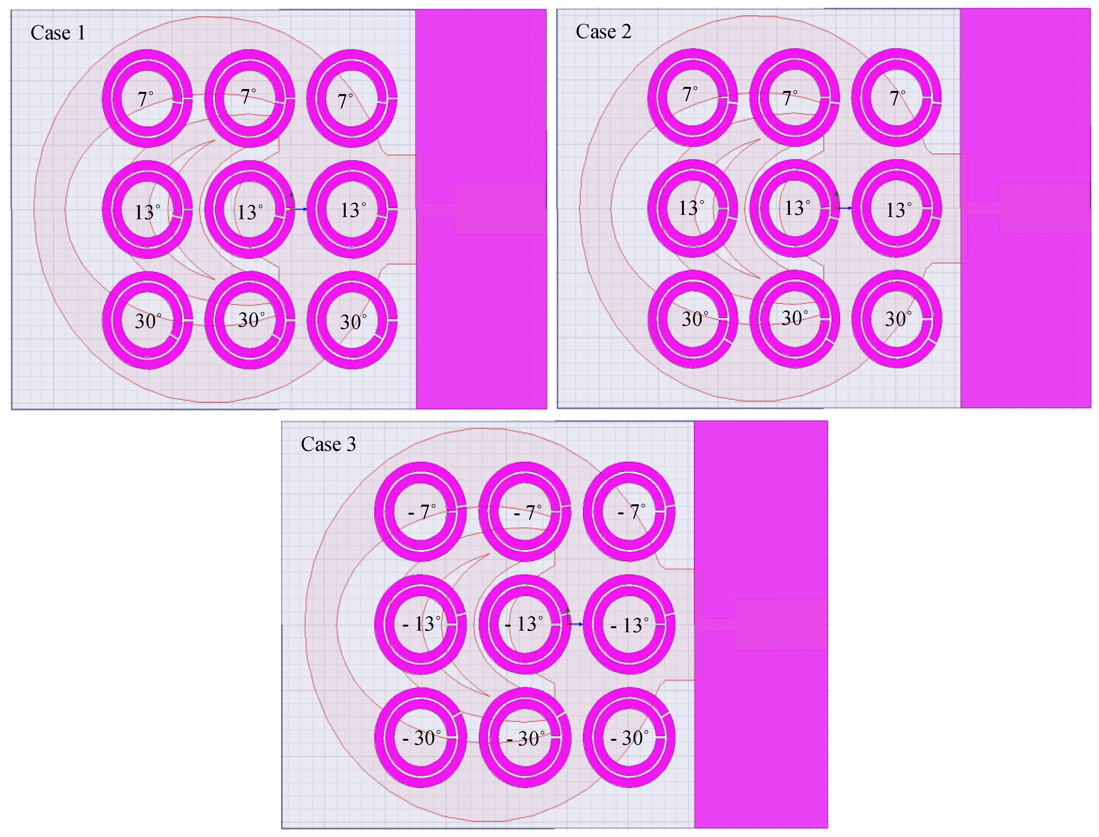
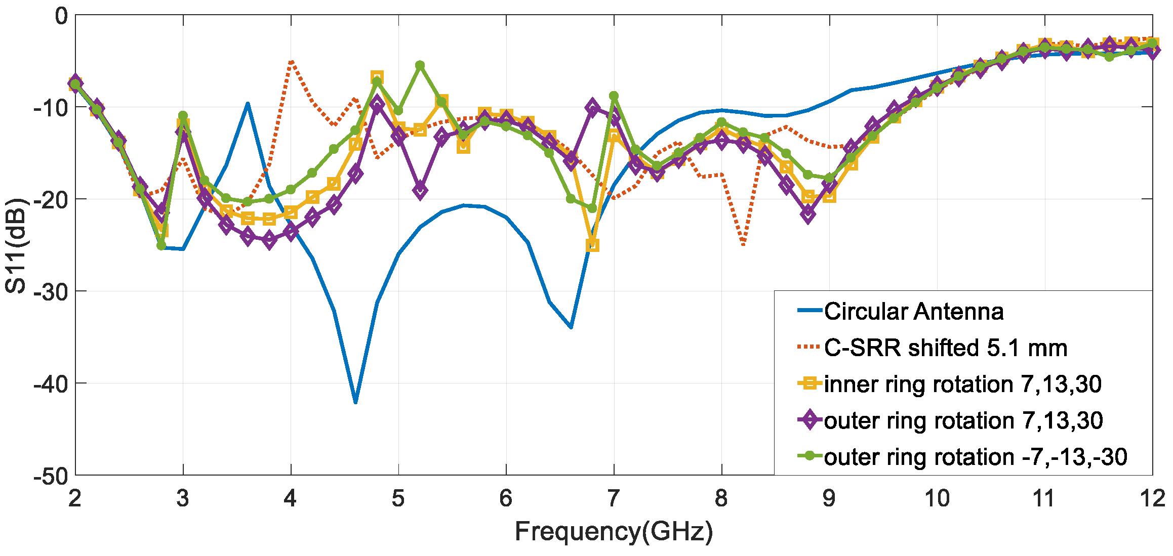
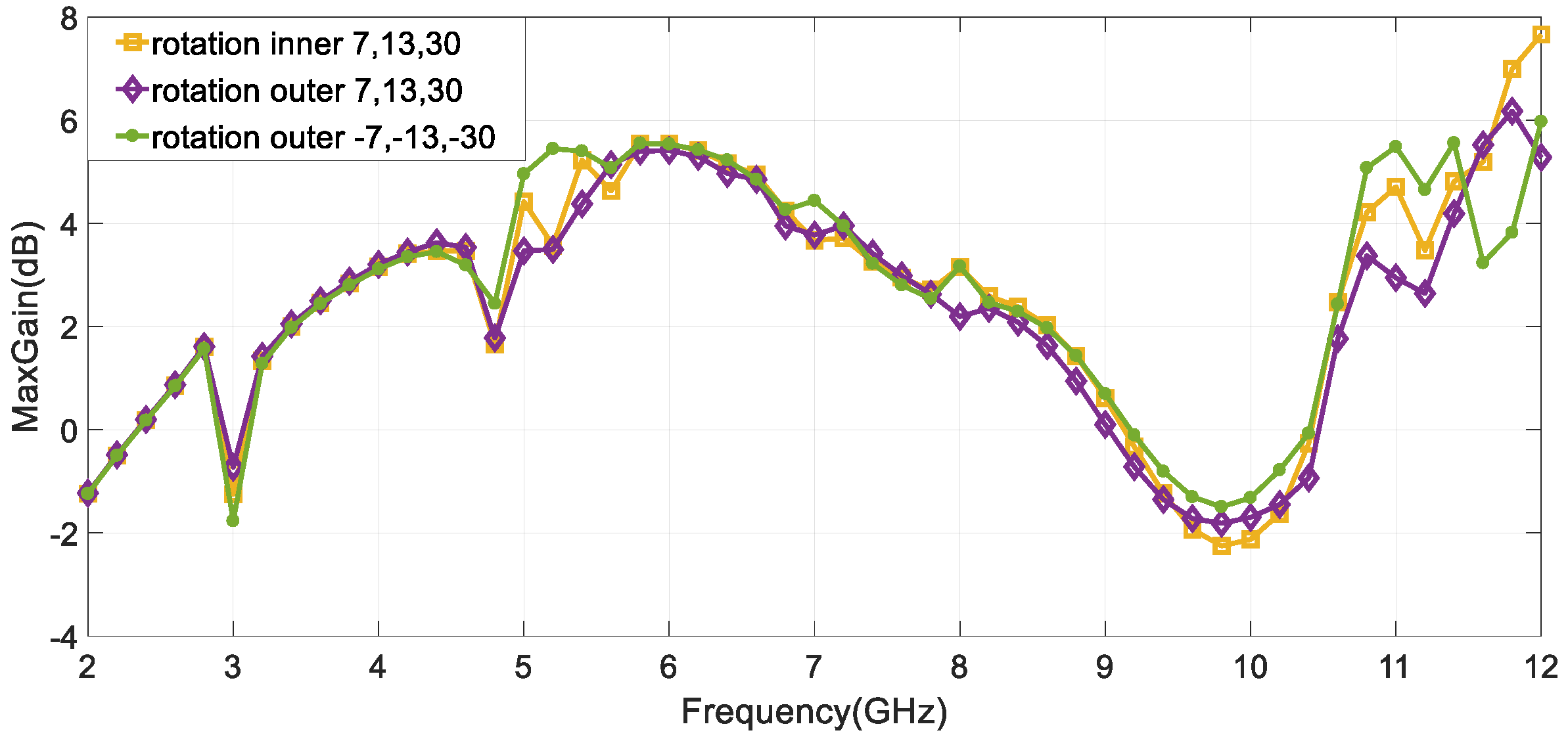
4.2. C-SRR and Ring Rotation
4.3. Implementation of Square-SRR
5. Conclusions
Author Contributions
Funding
Conflicts of Interest
References
- Stutzman, W.L.; Thiele, G.A. Antenna Theory and Design; John Wiley and Sons: Hoboken, NJ, USA, 1981. [Google Scholar]
- Balanis, C.A. Antenna Theory Analysis and Design, 3rd ed.; John Wiley and Sons: Hoboken, NJ, USA, 2005. [Google Scholar]
- Misra, G.; Agarwal, A.; Agarwal, K. Design and Performance Evaluation of Microstrip Antenna for Ultra-Wideband Applications Using Microstrip Feed. Am. J. Electr. Electron. Eng. 2015, 3, 93–99. [Google Scholar]
- Azim, R.; Islam, M.T. Printed Wide Slot Ultra-Wideband Antenna. In Advancement in Microstrip Antennas with Recent Applications; IntechOpen: London, UK, 2013; pp. 153–171. [Google Scholar]
- Islam, M.T.; Azim, R. Recent Trends in Printed Ultra-Wideband (UWB) Antennas. In Advancement in Microstrip Antennas with Recent Applications; IntechOpen: London, UK, 2013; pp. 173–201. [Google Scholar]
- Commission, F.C. Revision of Part 15 of the Commission’s Rules Regarding Ultra-Wideband Transmission Systems-First Report and Order; Federal Communications Commission: Washington, DC, USA, 2002.
- Foerster, J.; Green, E.; Somayazulu, S.; Leeper, D. Ultra-Wideband Technology for Short- or Medium-Range Wireless Communications. Intel Technol. J. Q2 2001, 5, 1–11. [Google Scholar]
- Chandrana, A.A.; Thankachanb, S. Triple Frequency Notch in UWB Antenna with Single Ring SRR loading. In Proceedings of the 6th International Conference on Advances in Computing & Communications, ICACC, Kochi, India, 6–8 September 2016. [Google Scholar]
- Haraz, O.; Sebak, A.R. UWB Antennas for Wireless Applications. In Advancement in Microstrip Antennas with Recent Applications; IntechOpen: London, UK, 2013; pp. 125–152. [Google Scholar]
- Farhood, A.D.; Naji, M.K.; Rhaif, S.H.; Ali, A.H. Design and analysis of dual band integrated hexagonal shaped microstrip UWB antenna. Indones. J. Electr. Eng. Comput. Sci. 2019, 15, 294–299. [Google Scholar] [CrossRef]
- Kardile, V.; Yadav, P.; Mishra, A. Design of Multiband Circular Microstrip Patch Antenna. Int. Res. J. Eng. Technol. (IRJET) 2016, 3, 1961–1963. [Google Scholar]
- Sultan, K.S.; Dardeer, O.M.A.; Mohamed, H.A. Design of Compact Dual Notched Self-Complementary UWB Antenna. Open J. Antennas Propag. 2017, 5, 99–109. [Google Scholar] [CrossRef][Green Version]
- Xiong, H.; Hong, J.-S.; Tan, M.-T.; Li, B. Compact Microstrip Antenna with Metamaterial for Wideband Applications. Turk. J. Electr. Eng. Comput. Sci. 2013, 21, 2233–2238. [Google Scholar] [CrossRef]
- Chandrasekaran, K.T.; Karim, M.F.; Alphones, A. Composite Right/Left-handed Structure based High Impedance Surface for Performance Enhancement of Planar Antennas. IET Microw. Antennas Propag. 2017, 11, 818–826. [Google Scholar] [CrossRef]
- Bautista, F.H.; Vargas, C.A.; Arcos, J.M.V. Negative Refractive Index in Split Ring Resonators. Materials 2013, 59, 141–146. [Google Scholar]
- Orten, P.Y.; Ekmekci, E.; Sayan, G.T. Equivalent Circuit Models for Split-ring Resonator Arrays. In Proceedings of the Progress in Electromagnetics Research Symposium, Cambridge, MA, USA, 5–8 July 2010; pp. 534–537. [Google Scholar]
- Balmaz, P.G.; Martina, O.J.F. Electromagnetic Resonances in Individual and Coupled Split-Ring Resonators. J. Appl. Phys. 2002, 92, 2929–2936. [Google Scholar] [CrossRef]
- Mahmud, M.Z.; Islam, M.T.; Misran, N.; Singh, M.J.; Mat, K. A Negative Index Metamaterial to Enhance the Performance of Miniaturized UWB Antenna for Microwave Imaging Applications. Appl. Sci. 2017, 7, 1149. [Google Scholar] [CrossRef]
- Hamad, E.K.I.; Nady, G. Bandwidth Extension of Ultra-wideband Microstrip Antenna Using Metamaterial Double-side Planar Periodic Geometry. Electromagn. Radio Eng. 2019, 28, 25–32. [Google Scholar] [CrossRef]
- Islam, M.T.; Ashraf, F.B.; Alam, T.; Misran, N.; Mat, K.B. A Compact Ultrawideband Antenna Based on Hexagonal Split-Ring Resonator for pH Sensor Application. Sensors 2018, 18, 2959. [Google Scholar] [CrossRef] [PubMed]
- Ebadzadeh, S.R.; Zehforoosh, Y. A Compact UWB Monopole Antenna with Rejected WLAN Band using Split-Ring Resonator and Assessed by Analytic Hierarchy Process Method. J. Microw. 2017, 16, 592–601. [Google Scholar] [CrossRef][Green Version]
- Apoorva. Designing of Circular Monopole Patch Antenna Loaded with Split Ring Resonator. Int. J. Adv. Res. Electr. Electron. Instrum. Eng. 2017, 6, 1–10. [Google Scholar]
- Li, R.; Zhang, Q.; Kuang, Y.; Chen, X.; Xiao, Z.; Zhang, J. Design of a Miniaturized Antenna Based on Split Ring Resonators for 5G Wireless Communications. In Proceedings of the Cross Strait Quad-Regional Radio Science and Wireless Technology Conference (CSQRWC), Taiyuan, China, 18–21 July 2019. [Google Scholar]
- Sharma, N.; Bhatia, S.S. Metamaterial Inspired Fidget Spinner-Shaped Antenna Based on Parasitic Split Ring Resonator for Multi-Standard Wireless Applications. J. Electromagn. Waves Appl. 2020, 34, 1471–1490. [Google Scholar] [CrossRef]
- Abdelkebir, S.; Mayouf, A.; Mayouf, F.; Zoubiri, B.; Devers, T. Study of Metamaterial Surface Wave Antenna Based on Split Ring Resonator. Microsyst. Technol. 2019, 25, 797–810. [Google Scholar] [CrossRef]
- Srifi, M.N.; Podilchak, S.K.; Essaaidi, M.; Antar, Y.M.M. Compact Disc Monopole Antennas for Current and Future Ultrawideband (UWB) Applications. IEEE Trans. Antennas Propag. 2011, 59, 4470–4480. [Google Scholar] [CrossRef]
- Ramakrishna, S.A. Physics of Negative Refractive Index Materials. Rep. Prog. Phys. 2005, 68, 449–521. [Google Scholar] [CrossRef]
- Singh, G.; Ni, R.; Marwaha, A. A Review of Metamaterials and its Applications. Int. J. Eng. Trends Technol. (IJETT) 2015, 19, 305–310. [Google Scholar] [CrossRef]
- Solymar, L.; Shamonina, E. Waves in Metamaterials; Oxford University Press: New York, NY, USA, 2009. [Google Scholar]
- Castro, P.J.; Barroso, J.J.; Neto, J.P.L. Experimental Study on Split-Ring Resonators with Different Slit Widths. J. Electromagn. Anal. Appl. (JEMAA) 2013, 5, 366–370. [Google Scholar] [CrossRef][Green Version]
- Al Nuaimi, M.K.T.; Whittow, W.G. Compact Microstrip Band Stop Filter Using SRR and CSSR: Design, Simulation and Results. In Proceedings of the European Conference on Antennas and Propagation (EuCAP 2010), Barcelona, Spain, 12–16 April 2010. [Google Scholar]
- Bulu, I.; Caglayan, H.; Aydin, K.; Ozbay, E. Compact Size Highly Directive Antennas Based on the SRR Metamaterial Medium. New J. Phys. 2005, 7, 1–10. [Google Scholar] [CrossRef]
- Patel, S.K.; Kosta, Y. Triband Microstrip-Based Radiating Structure Design Using Split Ring Resonator and Complementary Split Ring Resonator. Microw. Opt. Technol. Lett. 2013, 55, 2219–2222. [Google Scholar] [CrossRef]
- Aripin, Z.; Najmurrokhman, K.A.; Munir, A. Compact SRR-based Microstrip BPF for Wireless Communication. In Proceedings of the 2nd International Conference on Information Technology, Computer and Electrical Engineering (ICITACEE), Semarang, Indonesia, 16–18 October 2015. [Google Scholar]
- Marqués, R.; Mesa, F.; Martel, J.; Medina, F. Comparative Analysis of Edge- and Broadside-Coupled Split Ring Resonators for Metamaterial Design—Theory and Experiments. IEEE Trans. Antennas Propag. 2003, 51, 2572–2581. [Google Scholar] [CrossRef]
- Barroso, J.J.; Castro, P.J.; Neto, J.P.L. Experiments on Wave Propagation at 6.0 GHz in a Left-Handed Waveguide. Microw. Opt. Technol. Lett. 2010, 52, 2175–2178. [Google Scholar] [CrossRef]
- Kar, S.; Ghosh, M.; Kumar, A.; Majumder, A. Complementary Split Ring Resonator-Loaded Microstrip patch Antenna Useful for Microwave Communication. Int. J. Electron. Commun. Eng. 2016, 10, 1321–1325. [Google Scholar]
- Baena, J.D.; Bonache, J.; Martín, F.; Sillero, R.M.; Falcone, F.; Lopetegi, T.; Laso, M.A.G.; García, J.G.; Gil, I.; Portillo, M.F.; et al. Equivalent-Circuit Models for Split-Ring Resonators and Complementary Split-Ring Resonators Coupled to Planar Transmission Lines. IEEE Trans. Microw. Theory Tech. 2005, 53, 1451–1461. [Google Scholar] [CrossRef]
- Ballesta, F.A.; Gil, M.; Sindreu, M.D.; Bonache, J.; Martin, F. Characterization of Metamaterial Transmission Lines with Coupled Resonators through Parameter Extraction. In Metamaterial; Jiang, X.Y., Ed.; InTech Open Science|Open Minds: London, UK, 2012; pp. 303–320. [Google Scholar]
- Saha, C.; Siddiqui, J.Y. Theoretical Model for Estimation of Resonance Frequency of Rotational Circular Split-Ring Resonators. Electromagnetics 2012, 32, 345–355. [Google Scholar] [CrossRef]
- Saha, C.; Siddiqui, J.Y.; Antar, Y.M.M. Square Split Ring Resonator Backed Coplanar Waveguide for Filter Applications. In Proceedings of the URSI General Assembly and Scientific Symposium, Istanbul, Turky, 13–20 August 2011. [Google Scholar]
- Bahl, I.; Bhartia, P. Microwave Solid State Circuit Design, 2nd ed.; John Wiley and Sons: Hoboken, NJ, USA, 2003. [Google Scholar]


| Part | Length (mm) | Part | Length (mm) |
|---|---|---|---|
| L1 | 45.00 | L9 | 4.900 |
| L2 | 11.00 | L10 | 2.650 |
| L3 | 2.651 | L11 | 7.680 |
| L4 | 4.130 | W1 | 31.00 |
| L5 | 2.900 | W2 | 9.000 |
| L6 | 2.000 | W3 | 8.480 |
| L7 | 2.650 | W4 | 1.030 |
| L8 | 2.900 | W5 | 3.920 |
| Ellipse | Major Radius (mm) | Ration |
|---|---|---|
| A | 15.0 | 1 |
| B | 7.42 | 1.5 |
| C | 6.89 | 1.5 |
| D | 5.30 | 1.5 |
| Circular SRR | Square SRR | ||
|---|---|---|---|
| The Unit Cell Parameters | Value (mm) | The Unit Cell Parameters | Value (mm) |
| ) | 0.7 | ) | 0.5 |
| ) | 37 µm | ) | 35 µm |
| ) | 0.2 | ) | 0.2 |
| ) | 0.2 | ) | 0.8 |
| ) | 1.27 | ) | 1.27 |
| ) | 2.2 | ) | 2.6 |
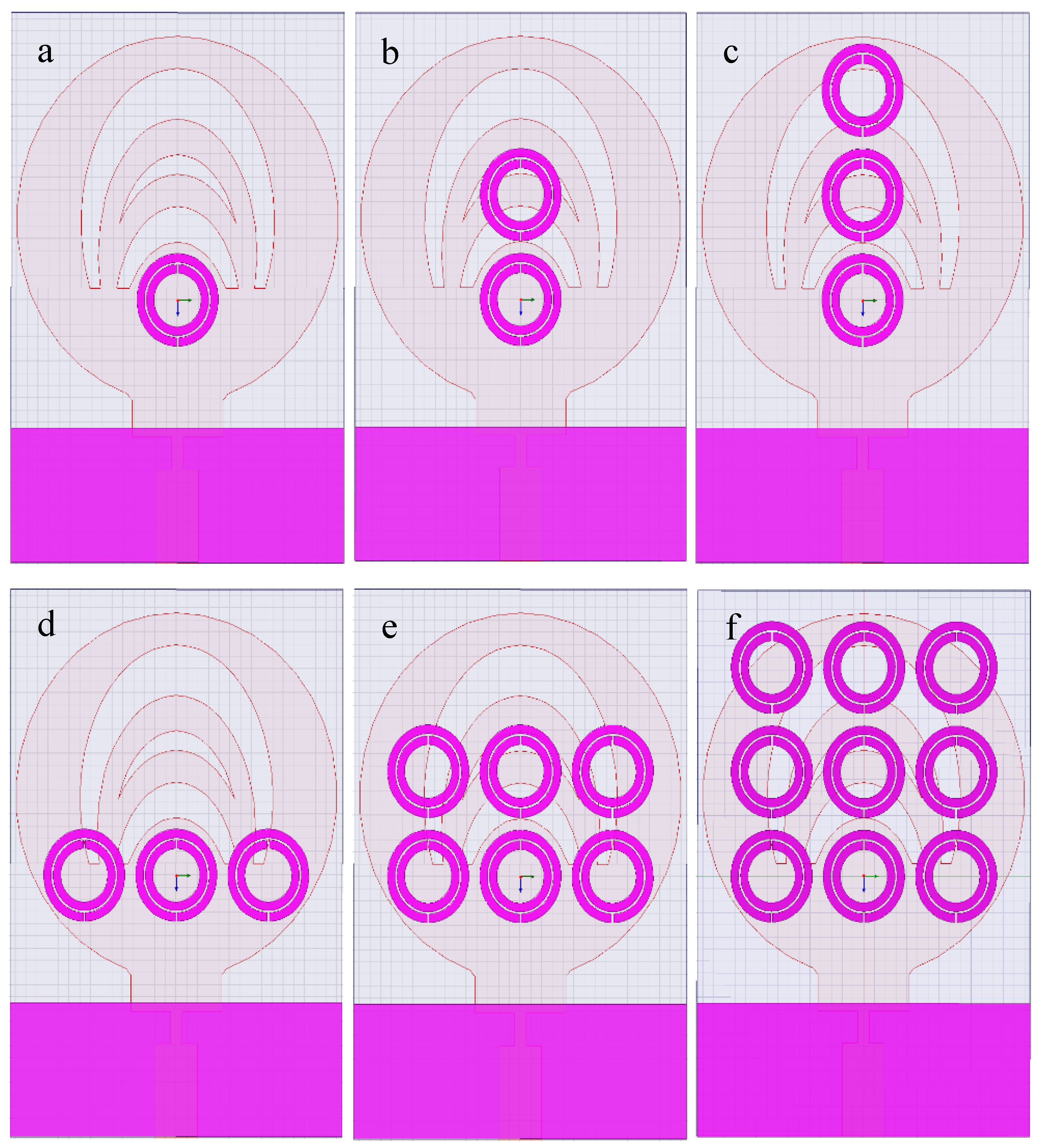
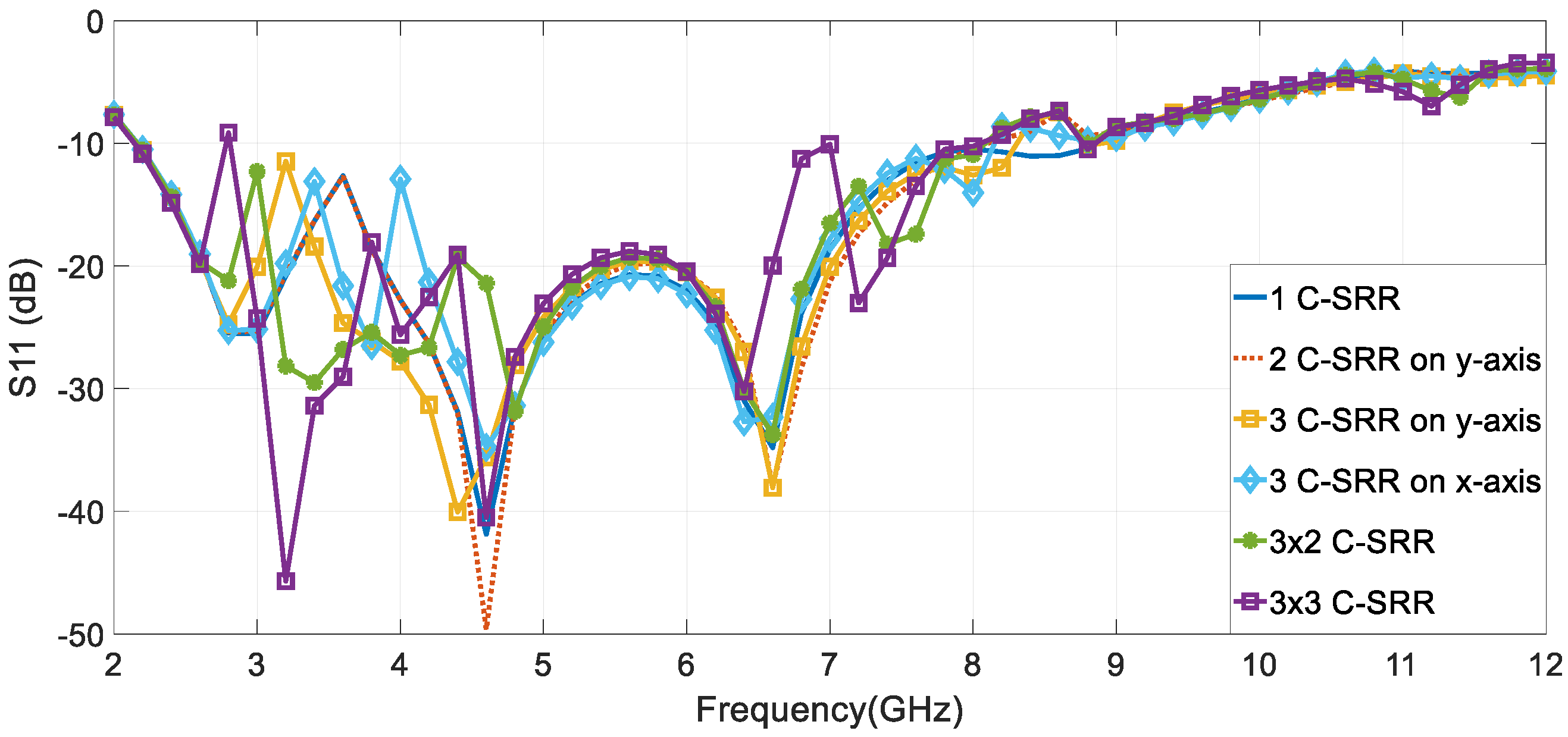
| Case | C-SRR No. | Frequency Bandwidth (GHz) | Return Loss (dB) |
|---|---|---|---|
| a | 1 | 3.5–9 | −42 |
| b | 2 on y-axis | 3.5–8 | −49.65 |
| c | 3 on y-axis | 3.2–8.2 | −40 |
| d | 3 on x-axis | 2.2–8 | −34.8 |
| e | 3 × 2 | 2.2–8 | −33.74 |
| f | 3 × 3 | 2.8–8 | −45.7 |
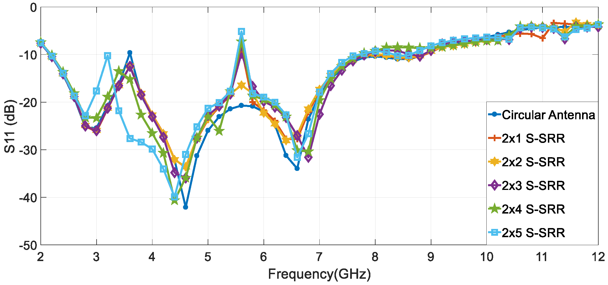
| Case | Array | Bandwidth (GHz) | Rejected Bands/Freq. (GHz) |
|---|---|---|---|
| a | 2 × 1 | 2.2–9 | 5.6 |
| b | 2 × 2 | 2.2–9 | - |
| c | 2 × 3 | 2.2–8 | 5.6 |
| d | 2 × 4 | 2.2–8 | 5.6 |
| e | 2 × 5 | 2.2–8 | 5.6 |
| f | 3 × 4 | 2.2–10 | 4.85–5.8 |
| g | 4 × 4 | 2.2–10 | 4.85–5.8 |
| h | 4 × 5 | 2.2–10 | 4.85–5.8 |
© 2020 by the authors. Licensee MDPI, Basel, Switzerland. This article is an open access article distributed under the terms and conditions of the Creative Commons Attribution (CC BY) license (http://creativecommons.org/licenses/by/4.0/).
Share and Cite
Serria, E.A.; Hussein, M.I. Implications of Metamaterial on Ultra-Wide Band Microstrip Antenna Performance. Crystals 2020, 10, 677. https://doi.org/10.3390/cryst10080677
Serria EA, Hussein MI. Implications of Metamaterial on Ultra-Wide Band Microstrip Antenna Performance. Crystals. 2020; 10(8):677. https://doi.org/10.3390/cryst10080677
Chicago/Turabian StyleSerria, Elham A., and Mousa I. Hussein. 2020. "Implications of Metamaterial on Ultra-Wide Band Microstrip Antenna Performance" Crystals 10, no. 8: 677. https://doi.org/10.3390/cryst10080677
APA StyleSerria, E. A., & Hussein, M. I. (2020). Implications of Metamaterial on Ultra-Wide Band Microstrip Antenna Performance. Crystals, 10(8), 677. https://doi.org/10.3390/cryst10080677