Article

Time Dependent Lyotropic Chromonic Textures in Microfluidic Confinements

Physics of Living Matter, Department of Physics and Materials Science, University of Luxembourg, 162 A, Avenue de la Faïencerie, L-1511 Luxembourg, Luxembourg
*
Author to whom correspondence should be addressed.
Crystals 2021, 11(1), 35; https://doi.org/10.3390/cryst11010035
Submission received: 10 November 2020 / Revised: 18 December 2020 / Accepted: 18 December 2020 / Published: 30 December 2020
(This article belongs to the Special Issue Early Career Stars of the Decade)

Abstract

:
Nematic and columnar phases of lyotropic chromonic liquid crystals (LCLCs) have been long studied for their fundamental and applied prospects in material science and medical diagnostics. LCLC phases represent different self-assembled states of disc-shaped molecules, held together by noncovalent interactions that lead to highly sensitive concentration and temperature dependent properties. Yet, microscale insights into confined LCLCs, specifically in the context of confinement geometry and surface properties, are lacking. Here, we report the emergence of time dependent textures in static disodium cromoglycate (DSCG) solutions, confined in PDMS-based microfluidic devices. We use a combination of soft lithography, surface characterization, and polarized optical imaging to generate and analyze the confinement-induced LCLC textures and demonstrate that over time, herringbone and spherulite textures emerge due to spontaneous nematic (N) to columnar M-phase transition, propagating from the LCLC-PDMS interface into the LCLC bulk. By varying the confinement geometry, anchoring conditions, and the initial DSCG concentration, we can systematically tune the temporal dynamics of the N- to M-phase transition and textural behavior of the confined LCLC. Overall, the time taken to change from nematic to the characteristic M-phase textures decreased as the confinement aspect ratio (width/depth) increased. For a given aspect ratio, the transition to the M-phase was generally faster in degenerate planar confinements, relative to the transition in homeotropic confinements. Since the static molecular states register the initial conditions for LC flows, the time dependent textures reported here suggest that the surface and confinement effects—even under static conditions—could be central in understanding the flow behavior of LCLCs and the associated transport properties of this versatile material.

1. Introduction

Lyotropic chromonic liquid crystals (LCLCs) are a class of lyotropic liquid crystals (LCs) that are formed by anisotropic assemblies of water-soluble disc-shaped molecules which have an aromatic core surrounded by ionic groups. Most commonly used chromonic LCs are sunset yellow (SSY), an azo dye used as a food additive, and disodium cromoglycate (DSCG), an anti-asthmatic drug. Unlike lyotropic LCs, LCLCs do not form micelles; rather, they stack up as linear aggregates, held together by non-covalent interactions which lead to self-assembled nematic (N) phase or columnar (M-phase) with a hexagonal arrangement [1,2,3,4]. In both the N- phase and the M-phase, the director is parallel to the columnar axis of the stacks, as was revealed by X-ray studies. The nematic phase consists of short columnar stacks of DSCG molecules and appears at room temperature for low DSCG concentrations, whereas with the increase in DSCG concentration, the stacks assemble into a two-dimensional hexagonal array of extended columns in the M-phase [5,6,7], archetypal herringbone and spherulite textures spanning a wide range of concentration and temperature conditions. The weak interaction forces underpinning the self-assembled phases render LCLCs highly responsive to external stimuli (temperature, concentration, pH, ionic content, etc.) and geometric constraints [1,2,3,4], thus bestowing distinctive properties such as negative birefringence and a large difference in elastic constants. Owing to the biocompatibility and anisotropic properties, LCLCs have been explored in biological applications such as for drug delivery [8], optical biosensors [9], as well in technological applications such as organic electronics and optical components [10]. Lately, LCLCs have also been explored as host systems for active bacterial systems [11,12].
The challenges involved with the alignment of LCLCs hinder its practical applications. Various techniques from traditional LC alignment methods such as rubbed polyimide [13], external fields [14], oblique evaporation [15], self-assembled monolayers [16], etc., to sophisticated and complex methods such as graphene deposition [17], sputter lithography [18], photo-patterning [19], and plasmonic photopatterning of the liquid crystal polymer network [20] have been explored to achieve uniform alignment. Recent studies by Peng et al. and Taras et al. showed that the photopatterned orientation of LCLC can be used to control the flow of active matter, which can be predesigned to streamline the chaotic movements of swimming bacteria [21,22]. These works demonstrate that precise control of LCLC alignment can be used to control the orientation of active matter and has potential in microcargo delivery and soft microrobotics. However, to align DSCG perpendicular to the surface, only a few techniques such as silanes [23], hydrophobic polymers [24], graphene [17], and parylene [25] have been successful. Recently, Guo and coworkers showed the use of two photon laser writing techniques to generate three-dimensional topographical structures that can be used to uniformly and precisely control the alignment of LCLCs [26] (Figure 1).
In the nematic phase, LCLCs are known to have an unusually low twist-elastic modulus [27,28] and large saddle-splay modulus that breaks the reflection symmetry and creates several new chiral director configurations when subjected to microscale confinements. Recently, a few research groups have studied the confinement induced reflection symmetry breaking and new chiral director configurations [25,28,29,30] of LCLCs. The chiral symmetry breaking for spherical droplets (tactoids) formed by both DSCG and SSY solutions of LCLCs have been reported [31,32]. Jeong and coworkers reported the formation of hexagonally faceted droplets when the system undergoes the transition from the nematic to columnar phase. When LCLCs are confined in glass capillaries with homeotropic boundary conditions, twisted escaped radial and twisted planar polar configurations have been reported. A third chiral configuration, the escaped twist configuration, was observed in capillaries with degenerate planar boundary conditions [28,30]. Dietrich et al. recently reported the same chiral twisted escaped radial configuration in the nematic phase of disc-like micelles of non-chromonic and achiral lyotropic LCs. A recent study showed that reflection symmetry breaking under confinement is not limited to LCLCs and is suggested to be a general phenomenon exhibited by the nematic phase formed by supramolecular aggregates [33]. On the other hand, Baza and coworkers explored the dynamics of the rheological properties of LCLCs under shear flow and showed that DSCG exhibits tumbling characteristics similar to LC polymers [34].
Despite continued efforts to understand LCLC rheological properties, motivated by both fundamental and applied interests, we still lack a mechanistic insight into the LCLC hydrodynamics at microscales—a universal variable in medical, industrial, and biological settings. With the advancement in soft lithography techniques that have enabled the precise design and modulation of microfluidic geometry, pressure, and boundary conditions, both biological and material technology have seen major advancements over the last decades [35]. Recent progress in liquid crystal microfluidics has demonstrated how hydrodynamics, in combination with surface anchoring and confinement, can be harnessed to generate tunable flow and topological structures with potential for novel applications. The works of Sengupta et al. [36,37,38] and others [39] have shown that by precisely tuning the flow of nematic LCs, anchoring conditions at channel walls, and confinement conditions in microchannels, interesting phenomenon such as defect-mediated flow at a low Reynolds number [40], a non-Poiseuille flow profile [41], hydrodynamic cavitation [42], and crosstalk between the topological fields [43] are observed. The works on nematic LCs in microconfinement have revealed significant insight into the interplay of topological defects with microflows of nematic LCs, with potential applications in microcargo systems [44,45], optofluidic systems [46,47,48], and fluidic resistance circuits [49]. Based on these works, recently, flow-induced deformations have also been studied in chiral nematic LCs [50,51] and blue phases. Spontaneous tunable flow structures [41,52] were given a second look by Čopar and coworkers [53], revealing a hidden non-equilibrium chiral nematic state that could be stabilized by tuning microchannel dimensions and the driving pressure.
The behavior of LCLCs in strict microfluidic environments still awaits exploration, with multiple key variables (that determine their interactions) yet to be uncovered and understood. As microfluidic environments offer distinct interplays between the surface, confinement, and viscous parameters, one expects rich and unique interactions emerging at the LCLC-microfluidic interfaces. By substituting thermotropic nematic LCs with LCLCs within microfluidic confinements, the authors observed a wealth of novel phenomena—under both static and dynamic conditions—which warrant fundamental investigations. Building on our insights from experiments on thermotropic LCs in strictly microfluidic confinements, here we continue with state-of-the-art soft lithography techniques to fabricate microchannels of different dimensions and modify the surface anchoring conditions on the channel walls. It is known from the study of thermotropic LCs in microfluidic environments that the initial conditions for flow-induced director response are defined by the static (no flow) conditions [52]. With a vision to comprehensively understand the flow-confinement-anchoring couplings in LCLCs confined within microchannels, here we analyze the fundamental no flow state of LCLCs within microfluidic environments. Specifically, we characterize how the LCLC self-organizes within microscale confinements as a function of three fundamental variables: (i) channel dimensions, (ii) anchoring conditions, and (iii) LCLC concentration. In doing so, we uncover a fourth factor—the experimental timescale—which could play an important role in establishing the static director configurations within PDMS-glass microchannels. Our results reveal that the set of four variables is fundamental in determining the outcome of flow experiments (flow results will be discussed elsewhere) and thus need to be taken into account when designing LCLC microfluidic experiments. In our first attempt to bridge the gap between LCLC dynamics and microfluidics, here we will focus on recent results on the temporal dynamics of LCLC textures formed by static DSCG solutions confined in PDMS-glass microchannels, spanning different aspect ratios ( A R = width/depth = w / d ) and anchoring conditions. The basic structure of DSCG along with the stack configurations representing different phases are shown in Figure 1.

2. Materials and Methods

Using a combination of precision microfluidics and polarization microscopy, we characterized the concentration dependent static LCLC textures. We compared three concentrations of DSCG and characterized the LCLC optical textures as a function of anchoring conditions and channel aspect ratios, using polarizing optical microscopy and image analysis. Our results indicate that the emergence and orientation of the LCLC micro-domains are highly sensitive to the confinement length scales and surface anchoring conditions. Additionally, a highlight of this work is the spontaneous nematic to columnar (M) phase transition in PDMS-glass microchannels, as a function of time (under steady state temperature conditions). The time of the appearance of the M-phase shows a strong dependence on the channel geometry (width and depth) and surface anchoring (degenerate planar vs. homeotropic), indicating the fundamental role played by the properties of the confining surfaces (specifically, PDMS in this case) that need quantitative discussions detailed in [55]. All our experiments were conducted in multiple replicates (a minimum of 3) to ensure the reproducibility of the results.

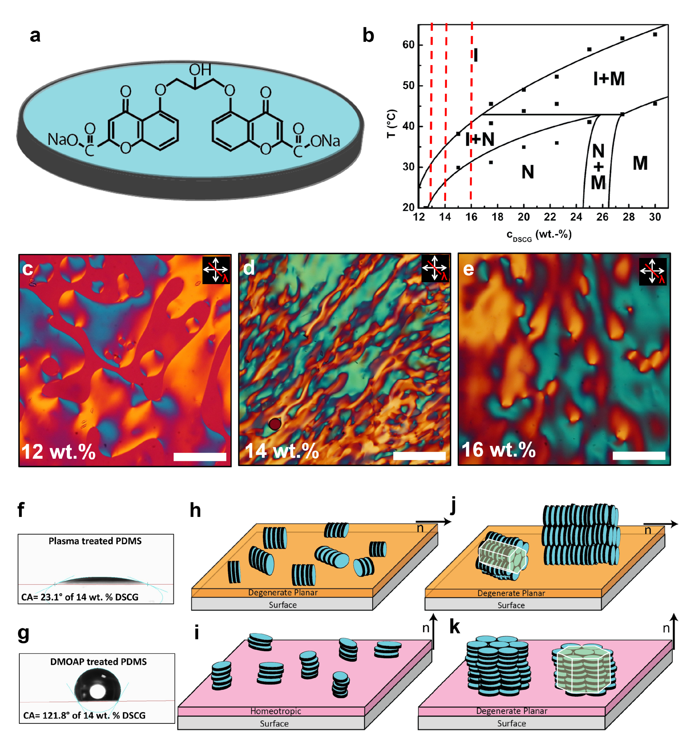
2.1. Materials and Solution Preparation

Disodium cromoglycate and dimethyloctadecyl [3-(trimethoxysilyl)propyl] ammonium chloride solution (DMOAP) were purchased from Sigma-Aldrich. 4-cyano-4-pentyl-1, 10-biphenyl (5CB) was procured from Synthon Chemicals and used as received. All the solvents used were of GC purity (≥99.8%) sourced from Carl-Roth. Solutions with 12, 14, and 16 wt.% of DSCG were prepared in Millipore water, vortexed for 30 min and stirred at room temperature for 12 h to obtain a homogeneous solution. The two component epoxy Araldit® Rapid was purchased from Carl-Roth. Glass capillaries were acquired from CM Scientific Ltd. (Vitrocom Vitrotubes®).

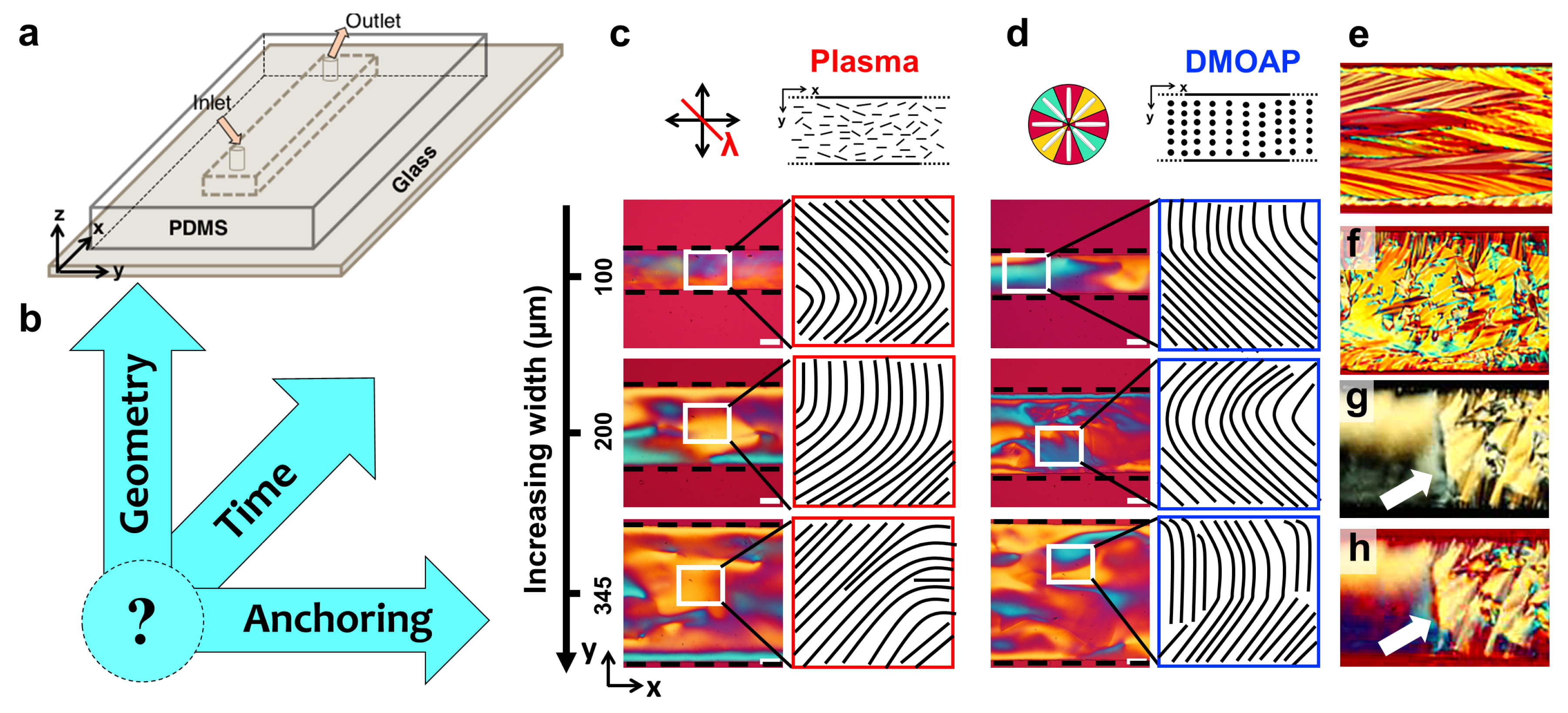
2.2. Microfluidic Confinement

The experimental protocol used in the fabrication of PDMS microfluidic channels is based on the setup described previously [40]. Briefly, microchannels were constructed using polydimethylsiloxane (PDMS, Sylgard 184, Dow Corning) reliefs and prepared by following the standard soft lithography techniques. The substrates were cleaned thoroughly with isopropanol and dried by placing the surfaces on a hot plate (80 ° C for 30 min). The molded PDMS reliefs were bonded to glass substrates after being exposed to air plasma. We prepared linear channels with a rectangular cross-section. The channel depth (d) was varied between 10 and 40 μ m, while the channel width (w) was varied between 100 and 345 μ m. The distance between the inlet and the outlet port was set to 20 mm, defining the length (l) of the channel. Different regions along the channel length were observed under the microscope to estimate the uniformity of functionalization. At both ends of the microchannel, cylindrical holes with a 1.5 mm diameter were punched through the PDMS to provide the housings for the tubings. Two Teflon (PTFE) tubes with a 0.5 mm inner diameter and a 1.58 mm outer diameter were inserted into each of the housings and served as connectors for the inlet-to-source and outlet-to-sink, respectively. For glass devices, hollow rectangle capillaries of dimensions (depth × width) 10 × 100 ± 10% μ m, 40 × 400 ± 10% μ m, and 100 × 1000 ± 10% μ m were used to study the texture development of LCLCs. Glass capillaries were either used as such or treated in order to obtain suitable surface anchoring and then filled with the liquid crystal.

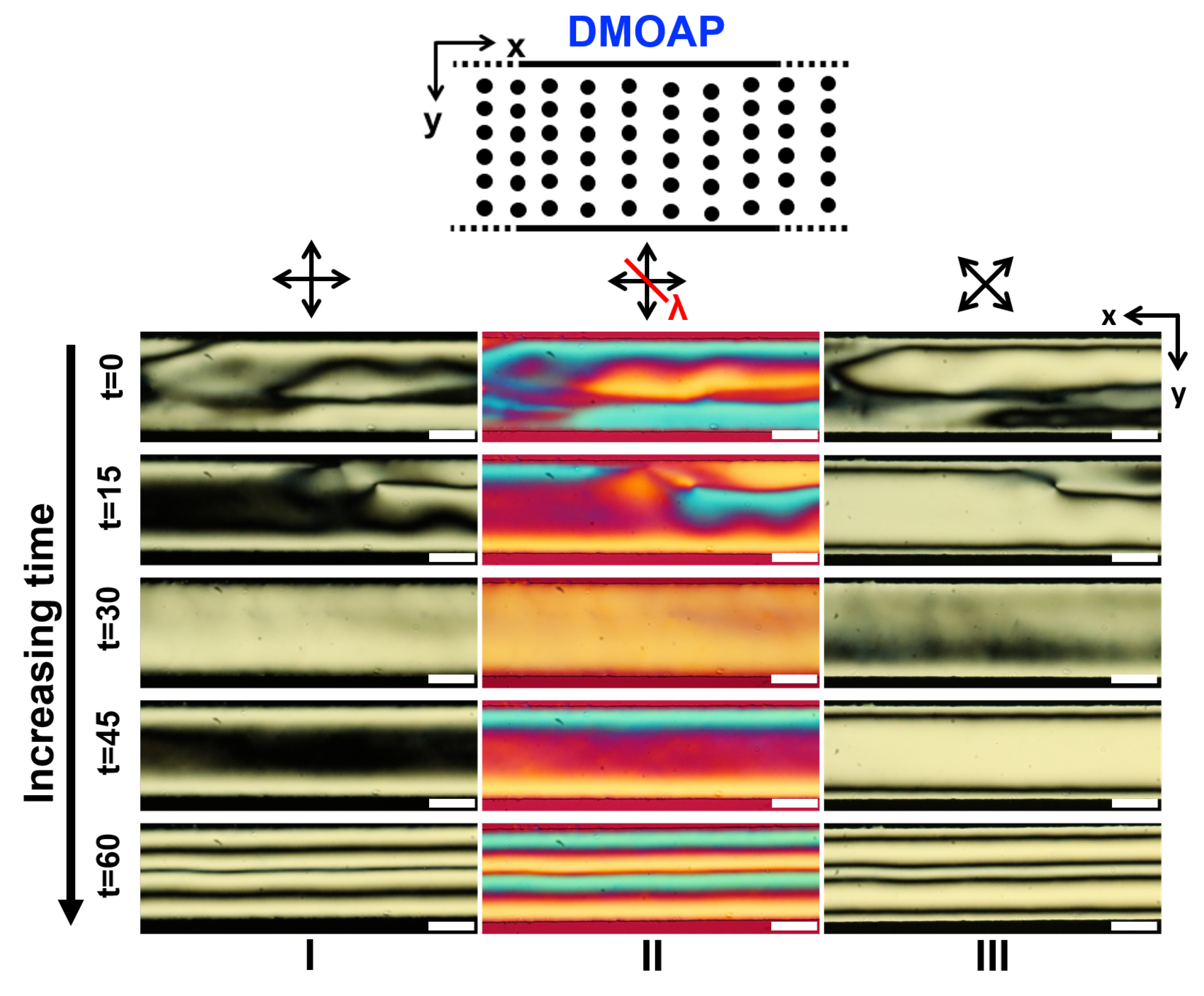
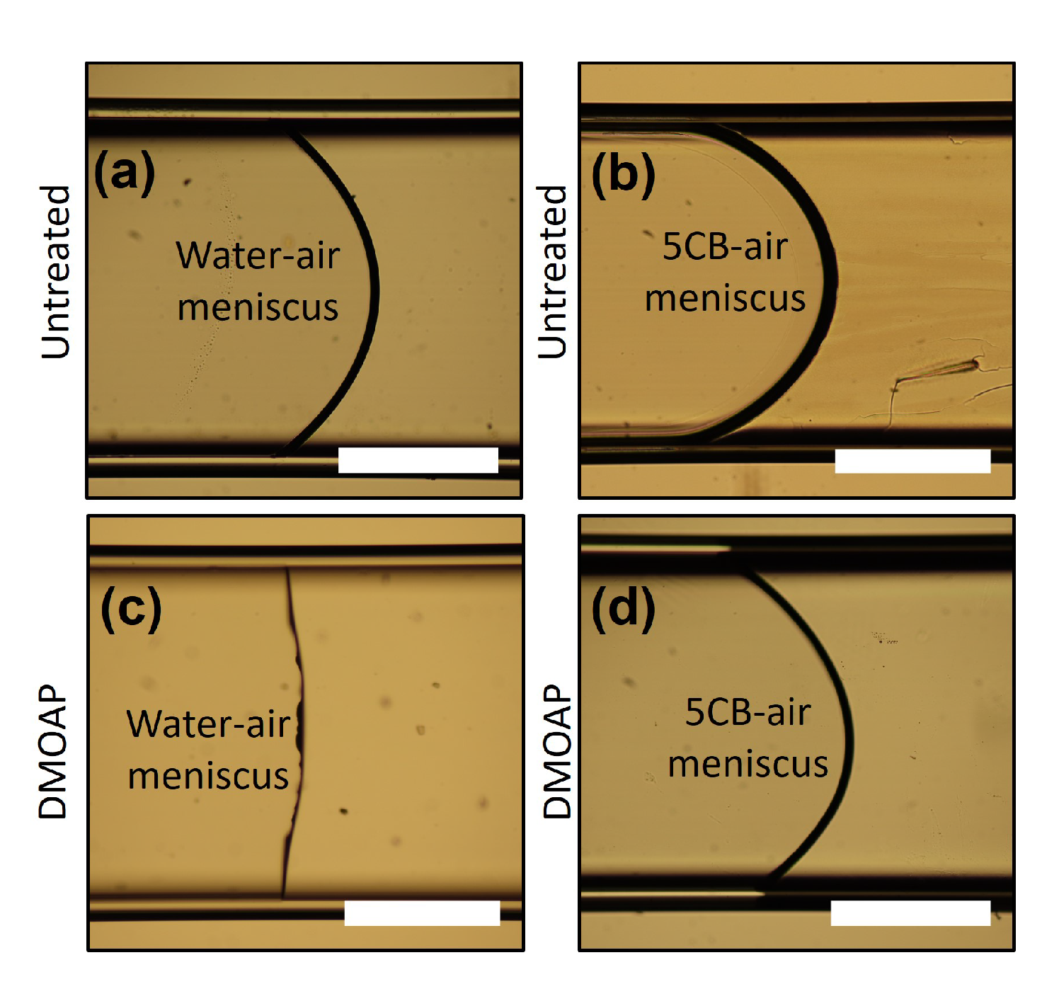
2.3. Surface Anchoring and Boundary Conditions

Microfluidic devices were functionalized for investigating LCLC textures within microchannels and glass capillaries possessing two distinct surface anchoring conditions: degenerate planar and homeotropic. Specific anchoring states within the microfluidic devices were achieved using a combination of different physical and chemical methods. We applied well studied plasma exposure (inducing degenerate planar anchoring) and DMOAP treatment (homeotropic) for surface functionalization of the PDMS-glass microchannels and glass-only devices [52,56]. The anchoring conditions were validated using thermotropic nematic 5CB as our control sample, for which detailed studies exist [57].
The degenerate planar surface anchoring was obtained after treatment of the PDMS surface by air plasma. Experiments under degenerate planar alignment conditions were conducted under freshly treated channels only. For homeotropic alignment, the channels were first filled with 0.4 wt.% aqueous solution of DMOAP and then dried in an oven at 80 ° C for 2 h to render both the PDMS and glass surfaces hydrophobic, inducing perpendicular (homeotropic) boundary conditions. In order to achieve homeotropic anchoring of the director at the LC-glass interface, the glass capillaries were filled with a 0.4 wt.% aqueous solution of DMOAP, and the solvent was allowed to evaporate before the capillary was filled with the liquid crystal. The anchoring inside the capillaries was characterized through the shape of the meniscus of water and nematic 5CB, relative to the shape inside native capillaries, as shown in Figure A2.

2.4. Filling the Microfluidic Devices

Glass-PDMS and glass capillaries were filled above the isotropic-nematic transition temperature of the LCLC solution for a given concentration of DSCG (12, 14, or 16 wt.%) at 45 ° C, either with a syringe and needle or capillary filling, respectively. Typically, a microchannel kept at 45 ° C was filled with a syringe (3 mL) with a beveled tip needle (23 gauge, 25 mm long, 0.6 mm outer diameter), to which a PTFE tube (0.5 mm inner diameter and 1.58 mm outer diameter) was connected. The other end of the PTFE tube was inserted into the microchannel. After filling, the microchannel was sealed with epoxy glue, to avoid flow-induced effects (e.g., alignment) and, crucially, to prevent water evaporation, which could change the DSCG concentration. Thereafter, microchannels were slowly cooled down to 22 ° C with a ramp rate of 1.5 ° C per minute. The capillaries were filled with 14 wt.% DSCG solution by capillarity at 45 ° C and then immediately sealed with epoxy to prevent water evaporation and to avoid flow-induced effects, then allowed to slowly cool down to 22 ° C with a ramp rate of 1.5 ° C per minute.

2.5. Optical Microscopy and Image Acquisition

The director orientation of LCLCs in the PDMS-microchannels and glass capillaries was determined using a polarized light microscope (Eclipse LV100N-POL, Nikon), equipped with ×5, ×10, ×20, and ×40 objectives and with a Linkam (PE120) heating/cooling stage. The samples were observed between crossed polarizers in the transmission mode using monochromatic light and several polarizer configurations. Additionally, the channels were oriented at 45 ° with respect to the polarizers and with and without the insertion of a 530 nm phase-retardation plate. The images (6000 × 4000 resolution) and videos (1920 × 1080 resolution) were acquired using a digital Canon EOS77D camera, and videos were recorded in full HD color at a frame rate of 25 frames per second. The image and video analysis was performed by using the tools ImageJ® and VideoMach®, respectively.

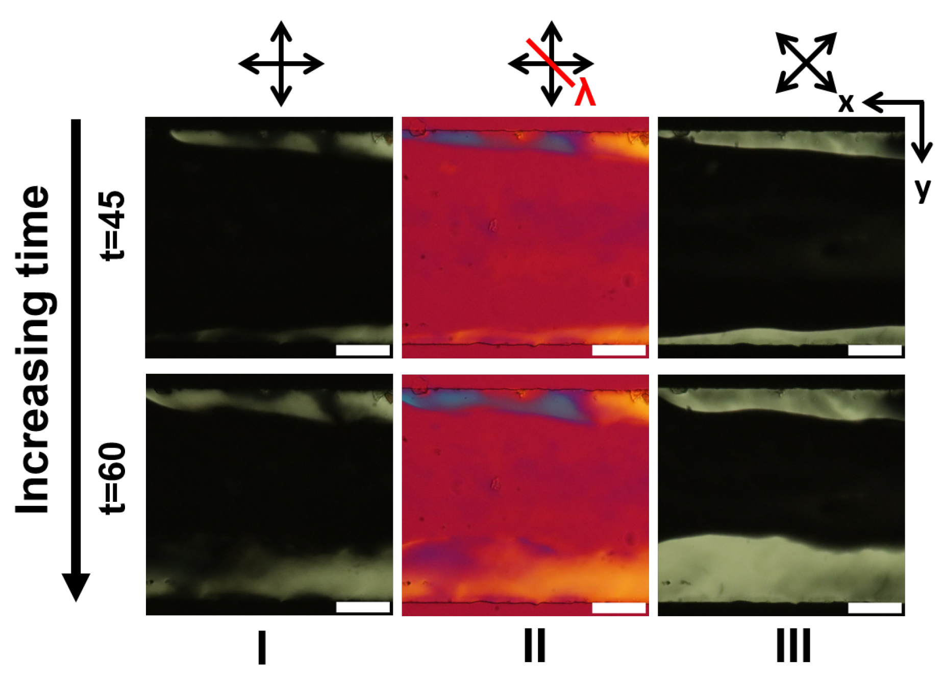
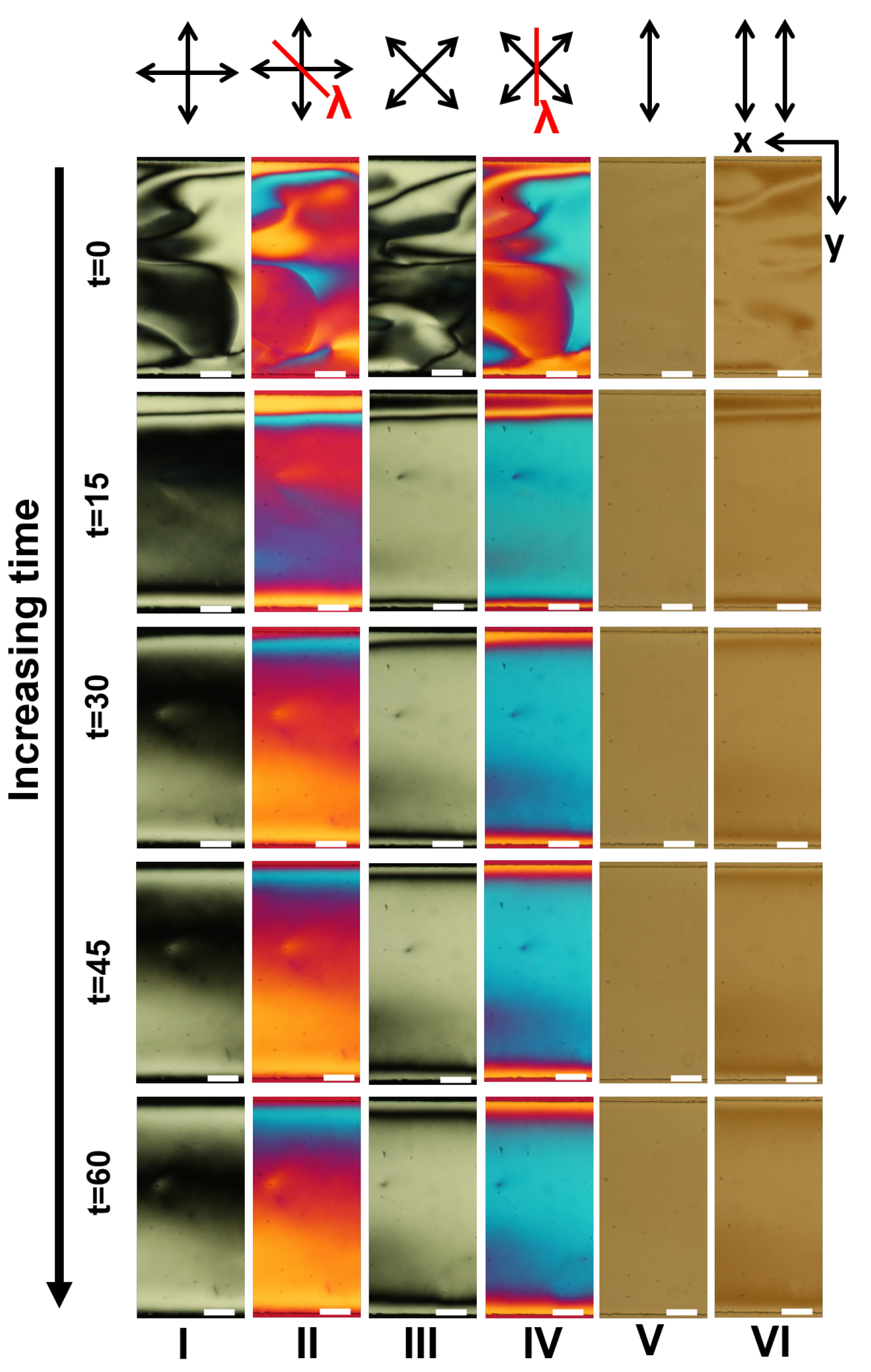
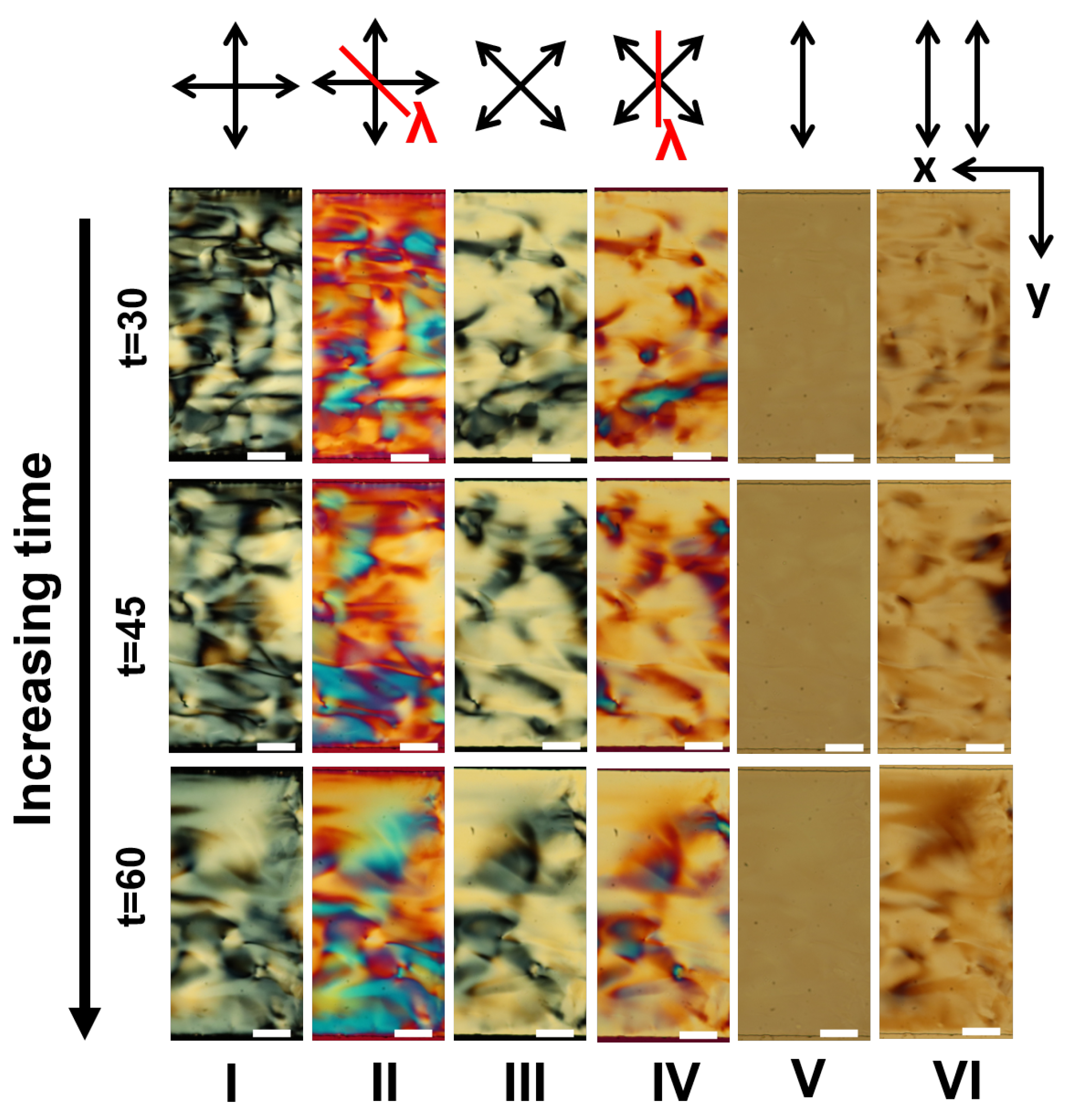
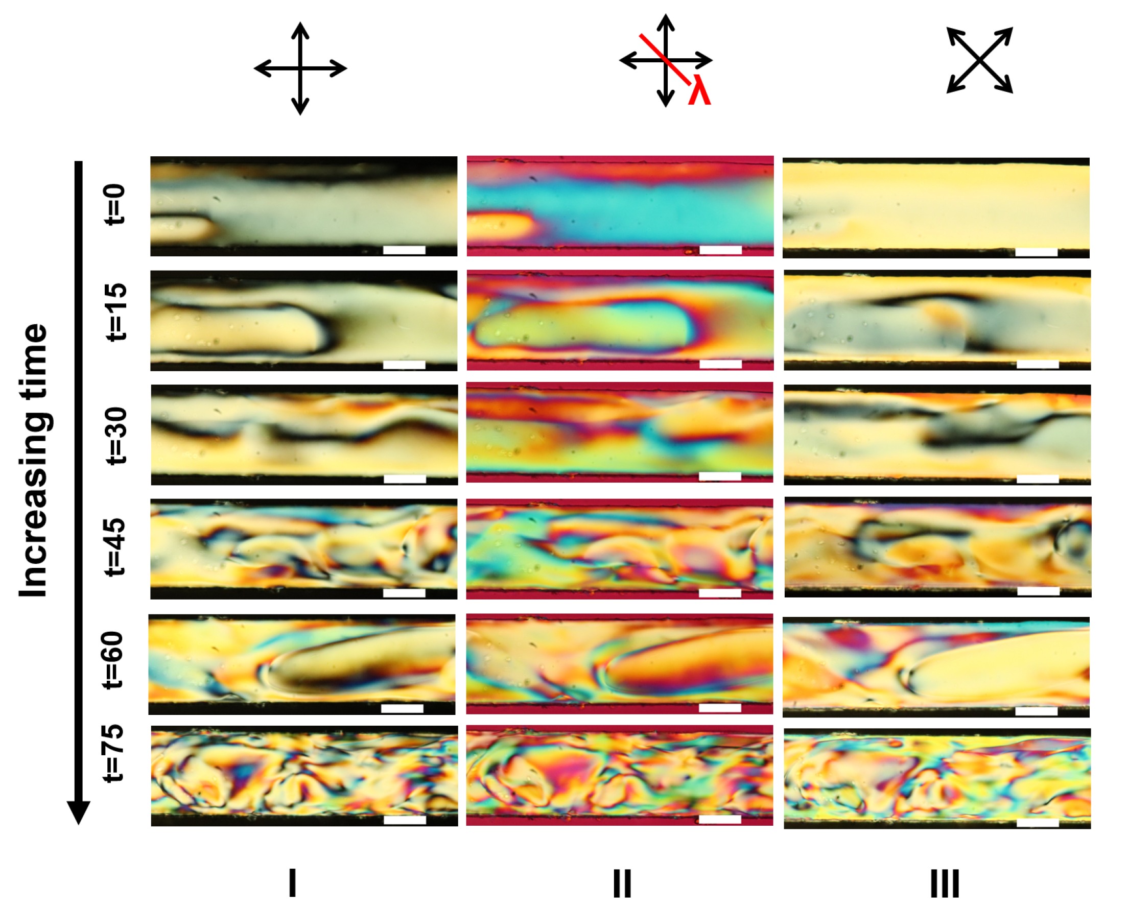
3. Results and Discussion

The goal of this work is to study the equilibrium textures LCLC under strict microfluidic confinements possessing distinct surface anchoring conditions and channel dimensions. Figure 2 shows the experimental variables considered here: channel dimension, anchoring conditions, and experimental timeline. For experiments conducted with PDMS-glass microchannels, all four walls possessed either a degenerate planar anchoring or homeotropic anchoring. From hereon, the results presented will focus on the concentration of DSCG of 14 wt.%, as our control case. Over the following sections, we present the dynamics of the emergence of the LCLC textures due to the DSCG solution. Based on the initial observations, a number of key questions—on the emergence of the dynamic and equilibrium LCLC textures—arise, the answers to which could identify specific roles of surface anchoring, confinement, and LCLC concentrations. Below, we present a step-by-step, detailed report on the emergent textures as a function of the aforesaid factors.

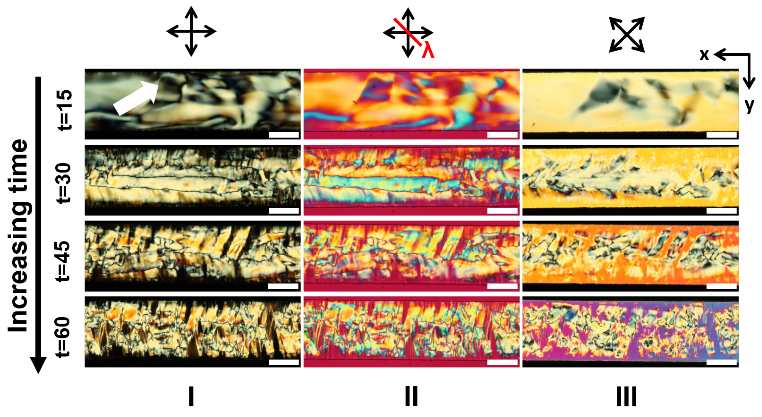
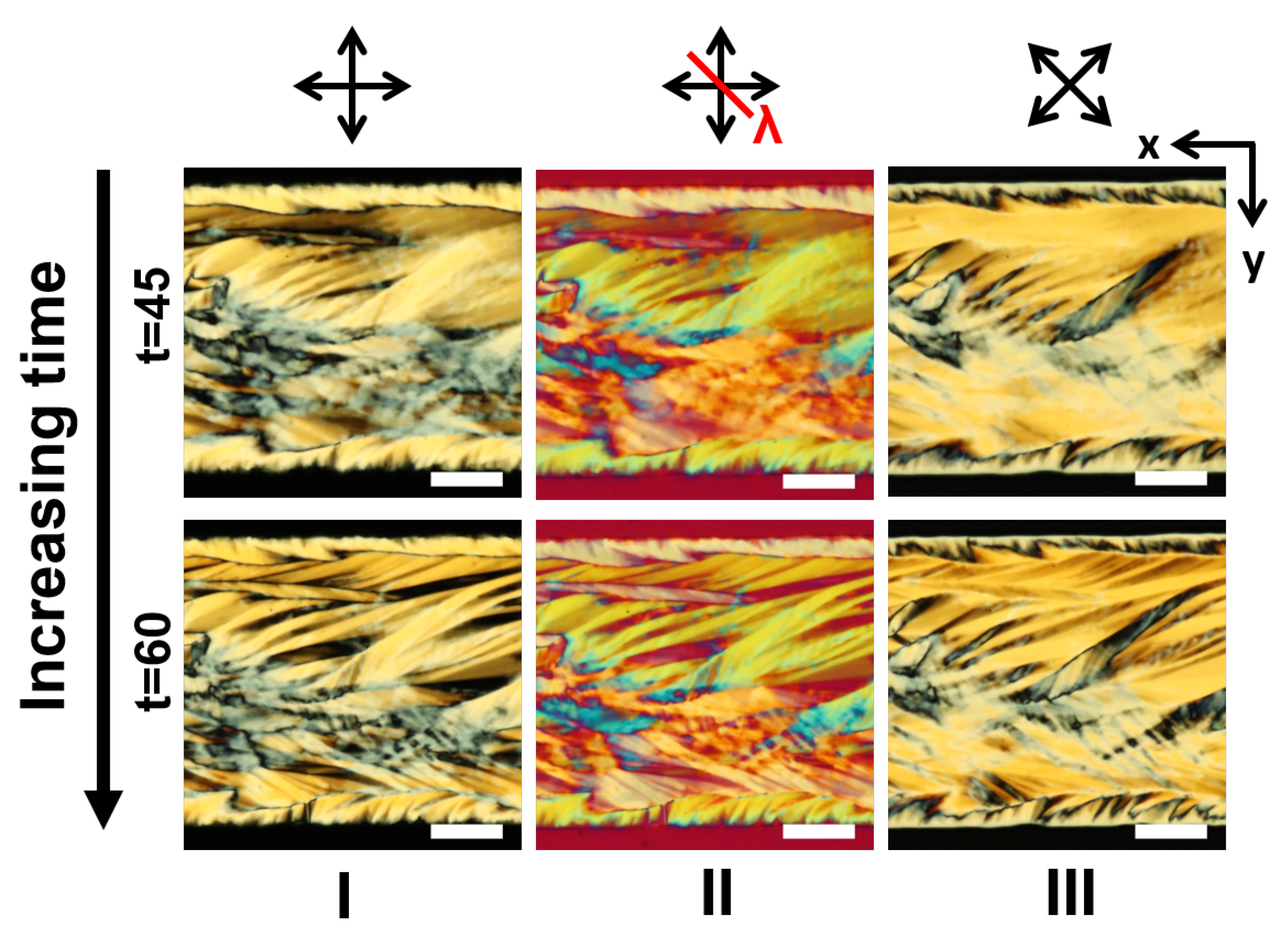
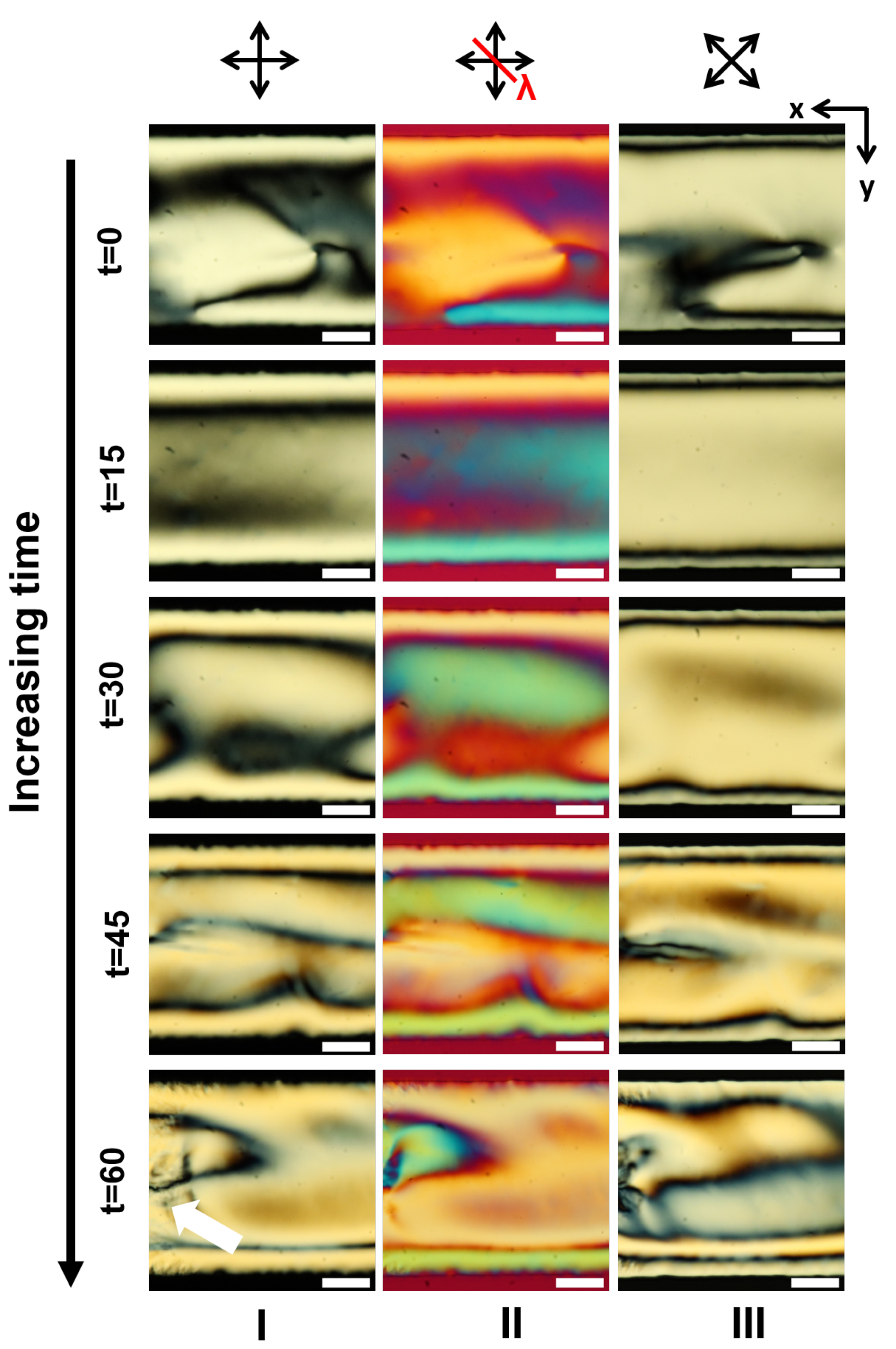
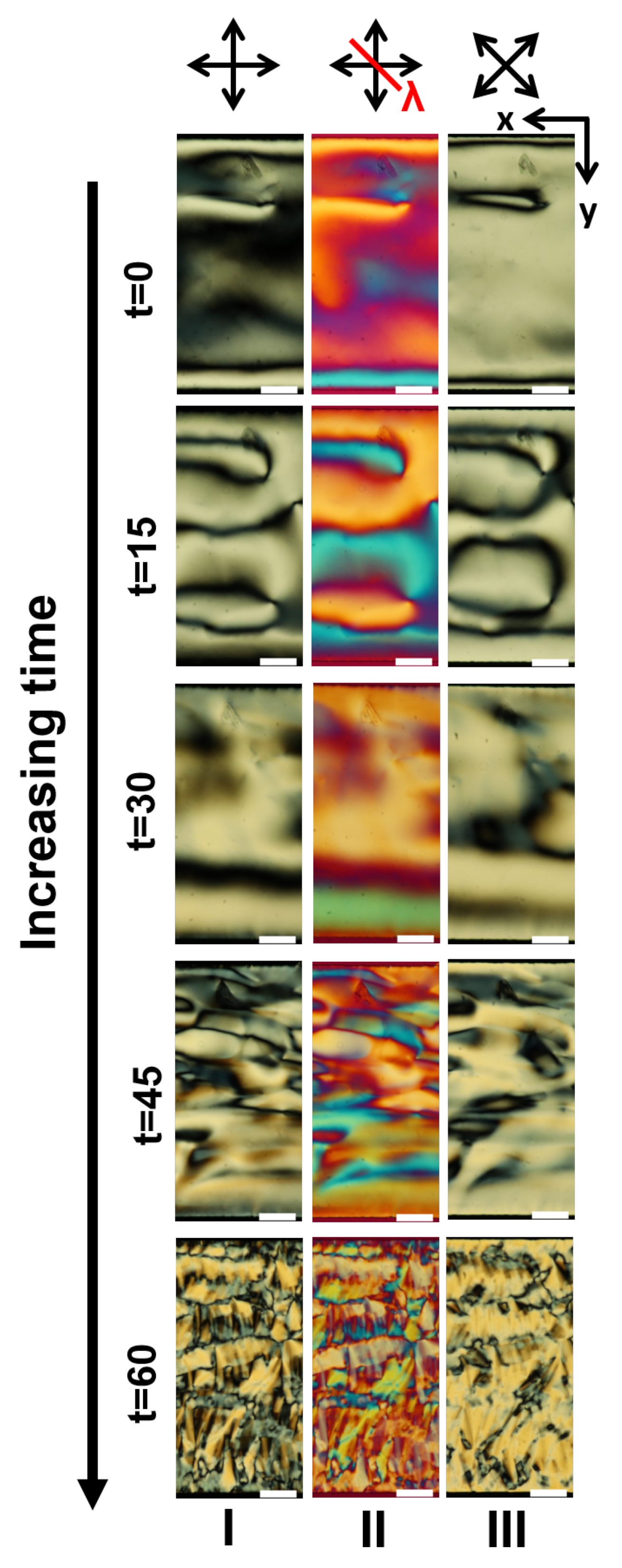
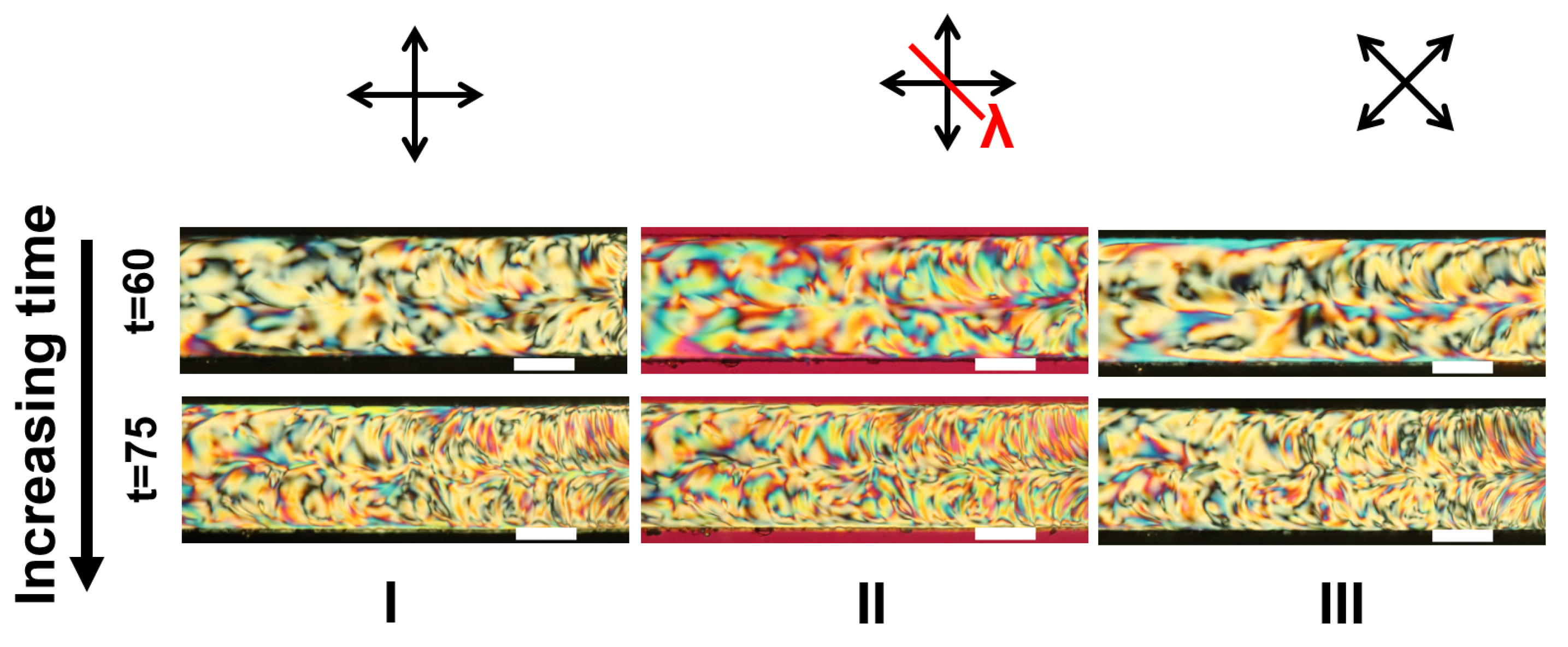
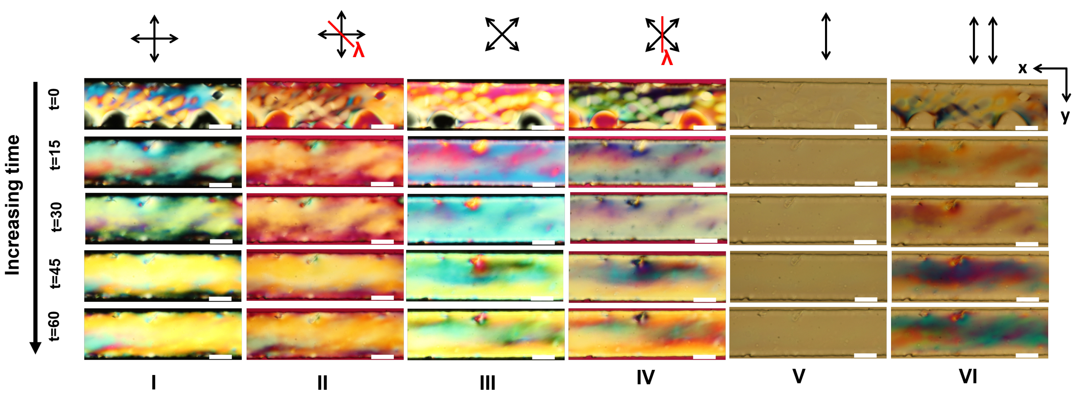
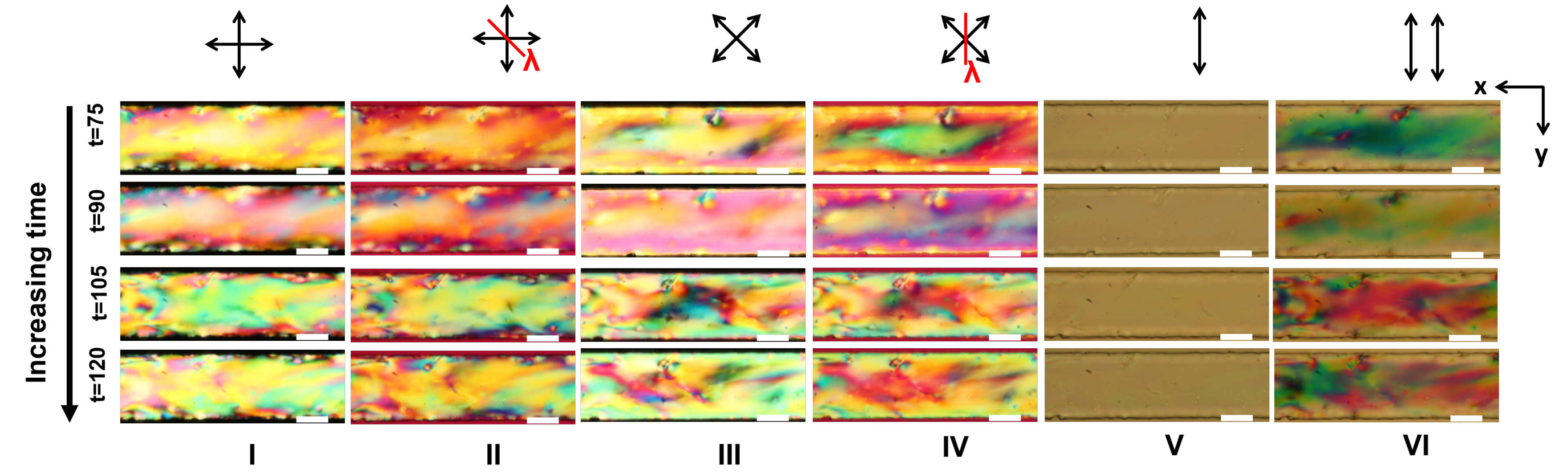
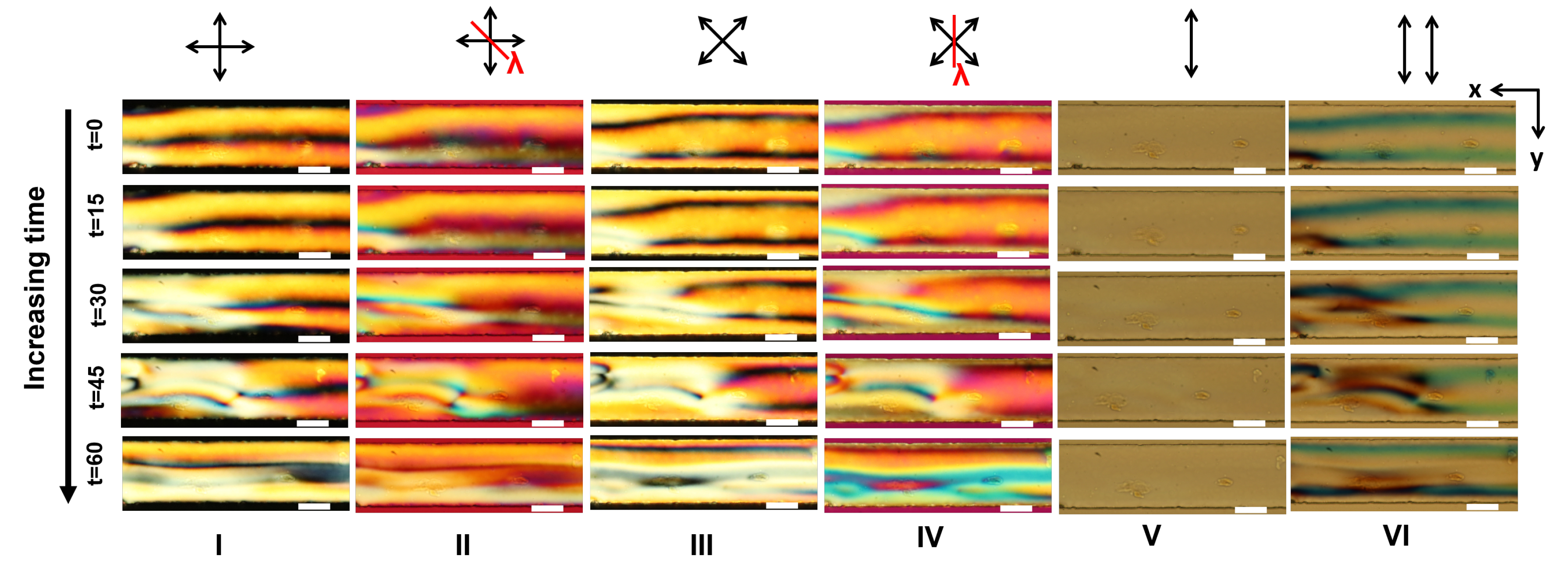
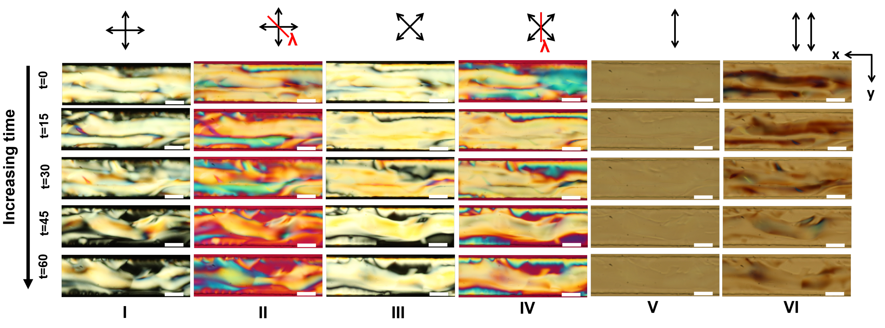
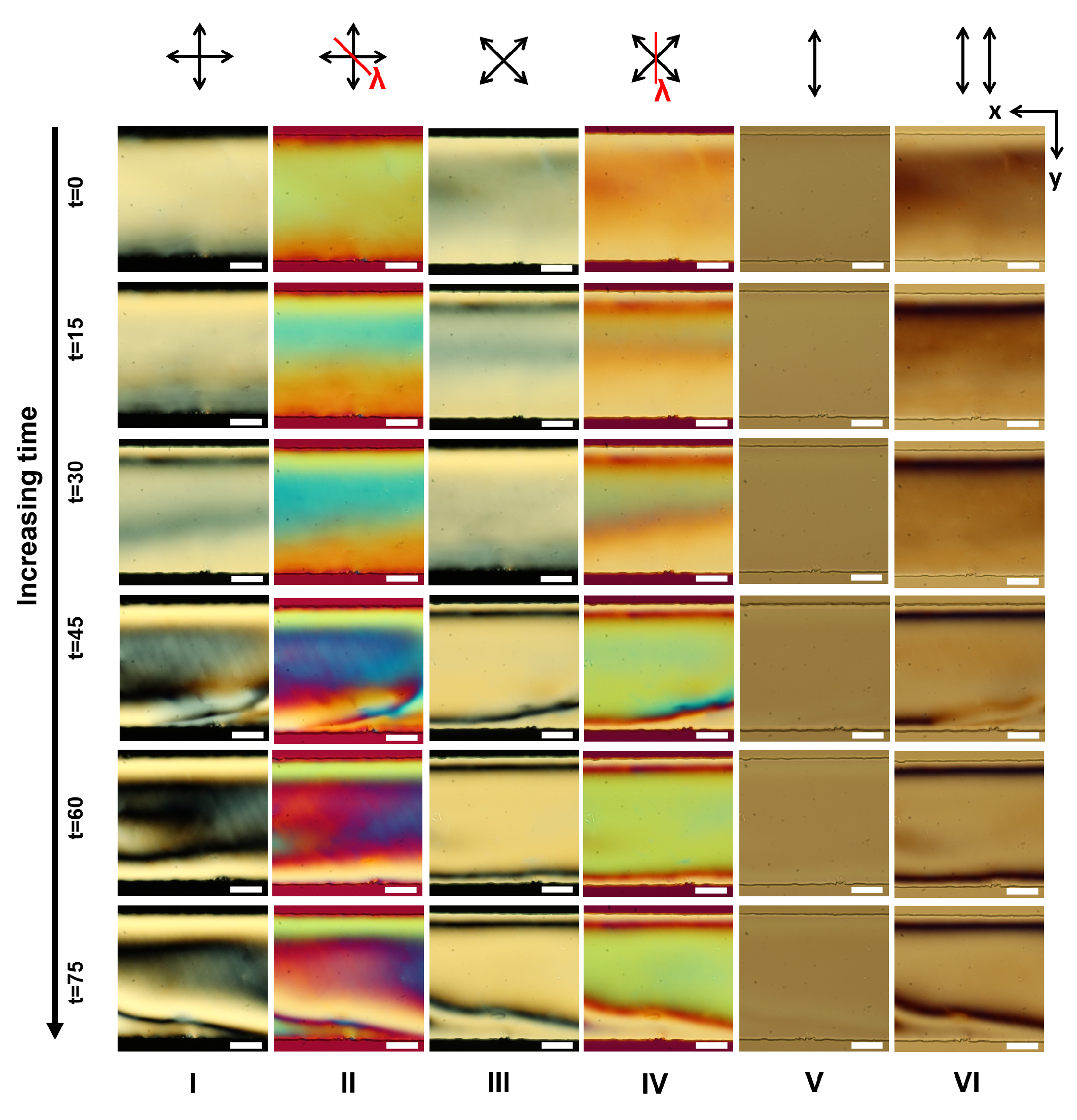
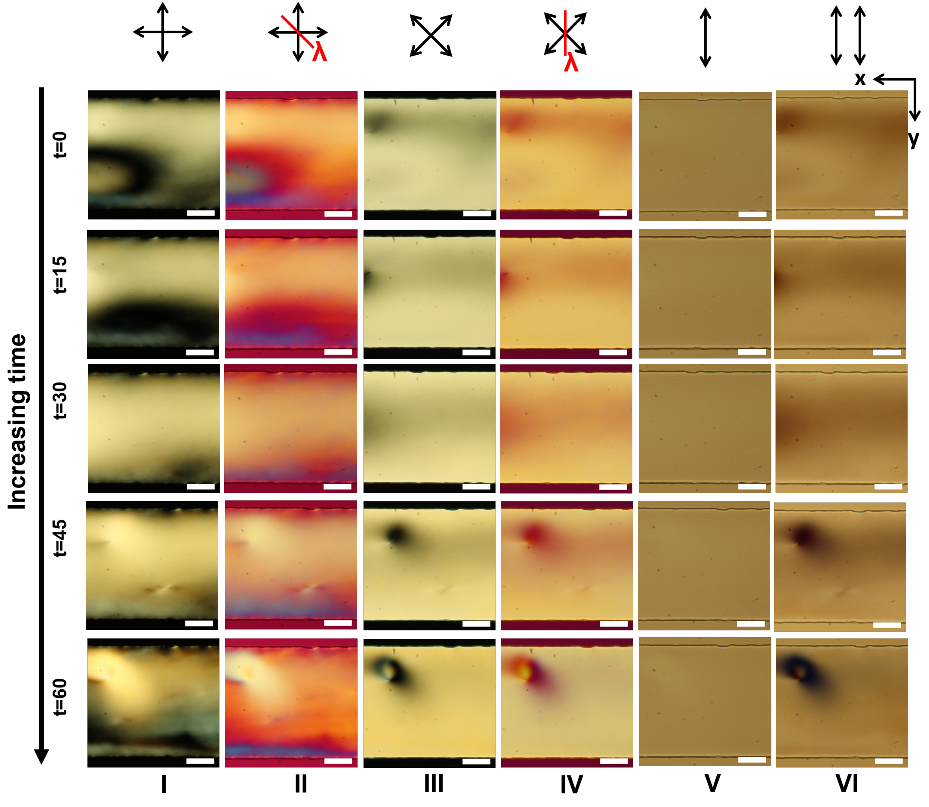
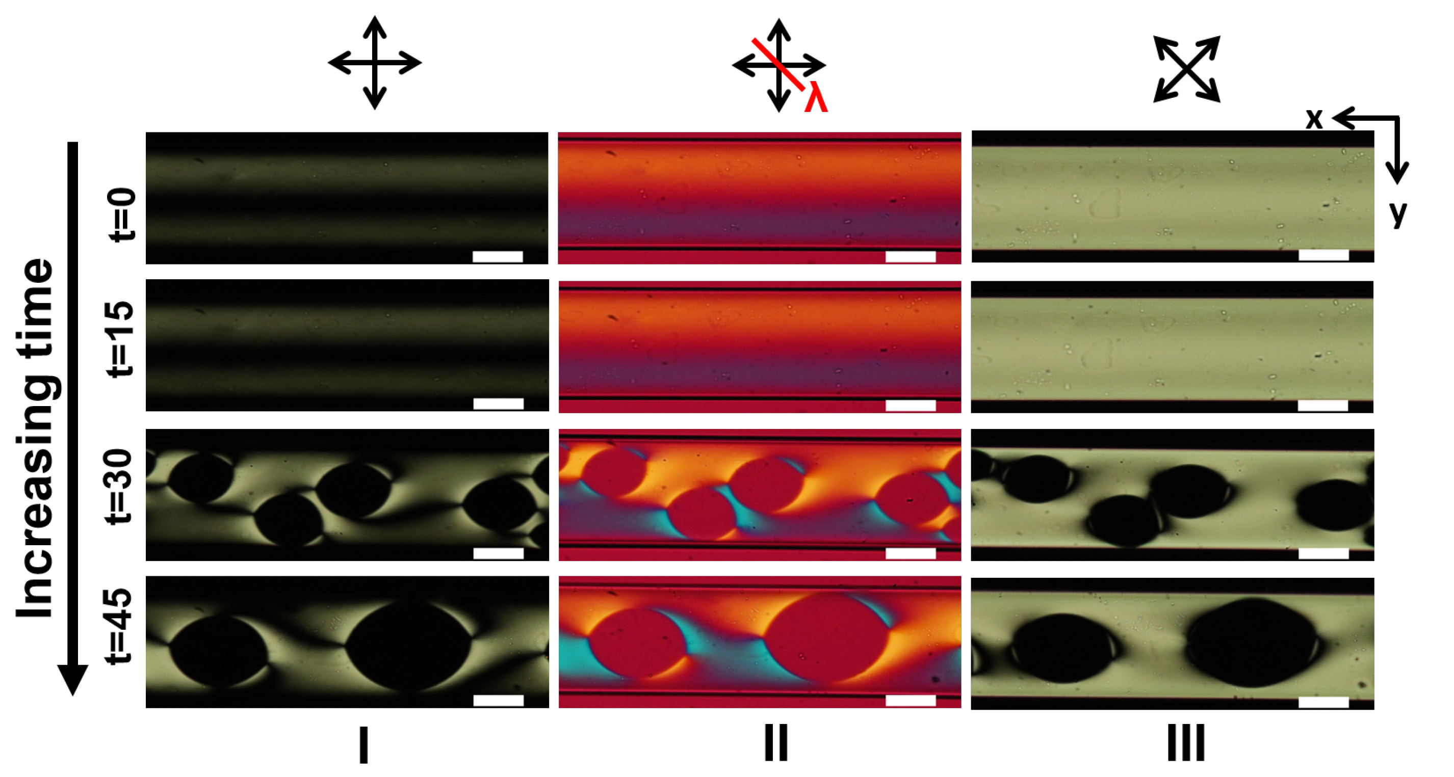
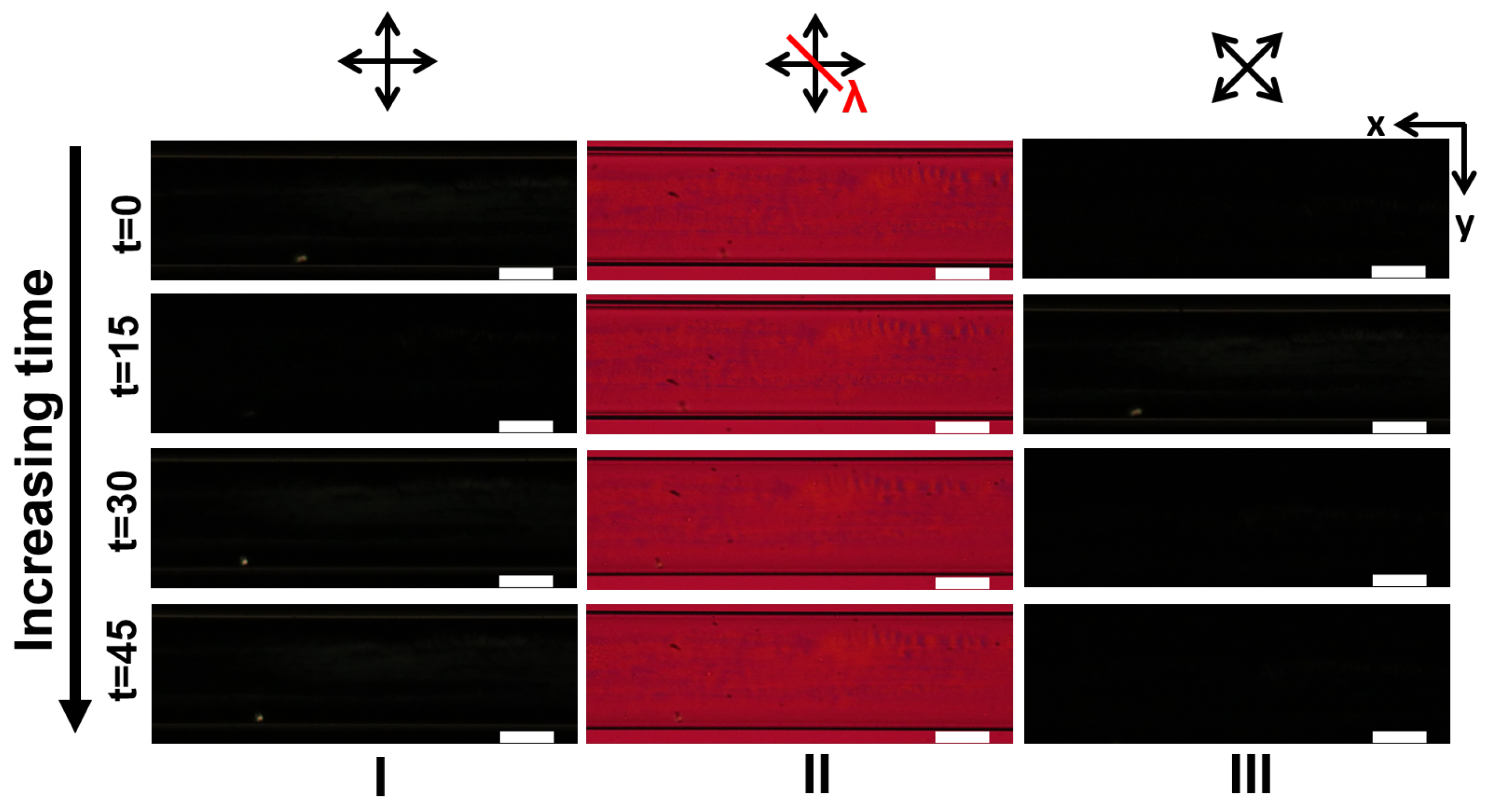
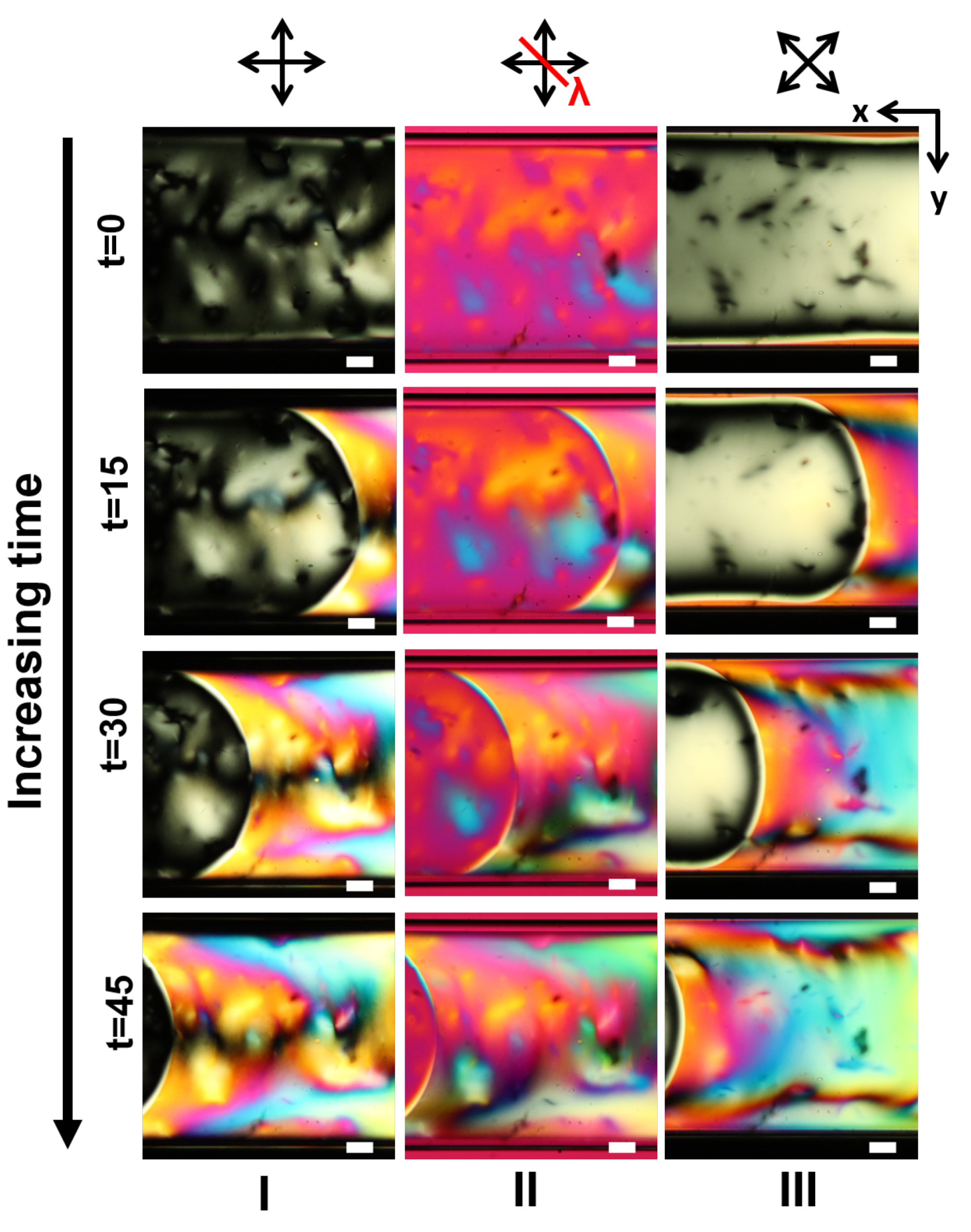
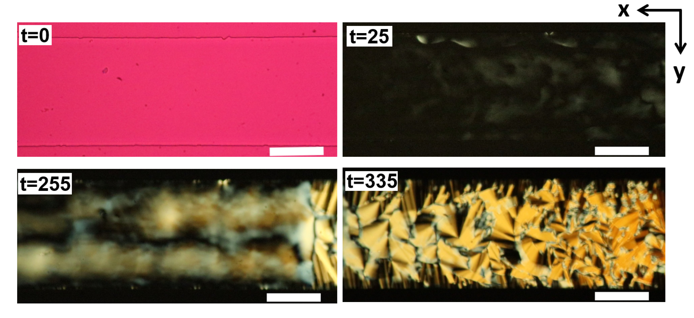
3.1. LCLC Microfluidic Textures Due to Degenerate Planar Anchoring

As shown in Figure 2a–f, POM imaging was used to characterize the developing director orientation within the microchannels. To create the degenerate planar anchoring, we employed plasma treatment (discussed previously) as a way to modify the microchannel surfaces to align the nematic phase exhibited by 14 wt.% DSCG. The plasma-treated microchannel was filled with DSCG, sealed, and cooled to 22 ° C with a ramp rate of 1.5 ° C per minute. In order to perform preliminary optical characterization of the textures, we scanned the entire channel at a lower magnification (×5), followed by images from selected areas (that best represented the overall director profile) taken at a higher magnification (×20), presented in Figure 2a–c. The corresponding textures in the homeotropic channels are shown in Figure 2d–f, which interestingly, right after the isotropic to nematic phase transition, resemble the degenerate planar textures texture. The anchoring condition was confirmed to be homeotropic by filling in 5CB and comparing the resulting texture with those in our previous works.
Figure 3 captures the time evolution of the DSCG textures within channels possessing degenerate planar anchoring. The dimension of the microchannel was kept fixed, with an A R 10 (w = 100 μ m, d = 10 μ m). Figure 3 (I–II) shows the POM micrographs obtained from a combination of different polarizer orientations, used to deduce the average molecular orientations corresponding to the planar textures. The birefringent domains appear shortly after the sample is cooled down below the isotropic-nematic phase transition temperature and stabilize over a timescale of 60 min. This appears as dark and bright regions between crossed polarizers, which show the formation of randomly oriented planar DSCG domains. The textures were further characterized using a λ -retardation plate along with the crossed polarizers (II). It may be worthwhile to note here that the DSCG (nematic and M-phase) possesses negative birefringence [58]; thus, in our POM micrographs with λ -retardation plates, the regions in yellow represent the nematic director orientation parallel to the slow axis of the retardation plate (please see Figure 2 for the reference color wheel). The region, where the director is oriented perpendicular to the slow axis of the retardation plate, appears blue [59]. The color variation can be attributed to the varying LC director orientations of microdomains formed by LCLC stacks in the nematic phase. In order to determine the stability of the planar textures, we checked the texture evolution every 15 min after the ramp had finished, for at least 60 min. Our observations reveal that initially (right after transition, t = 0 min), the DSCG solution has degenerate planar orientations. Different parts of the microfluidic channel were monitored to ascertain the homogeneity of the textures along the channel length. For the region of interest presented here, the planar nematic textures were found to be stable and homogeneous for about 60 min.
Interestingly, within similar timescales, isolated microdomains of the M-phase (visualized as non-planar static nematic textures) appeared, as shown in (Figure 4). Starting from a degenerate alignment, such textures grew and propagated over time, ultimately stabilizing into a herringbone configuration, a classical M-phase texture observed in LCLC materials. Figure 4, Figure 5 and Figure A18 (I) present different manifestations of the M-phase observed in our experiments. Tone et al. reported a similar degenerate planar texture for a 13 wt.% DSCG solution in polylysine-coated LC glass cell [15]. It was also observed that the degenerate planar texture evolved to a ribbon structure, a texture corresponding to the coexistence of the M and isotropic phase. As there is no preferential alignment of the director along any direction, the DSCG stacks orient randomly, forming a multi-domain structure of different orientations of the director. However, the timescale over which the planar textures transition from nematic to herringbone (M-phase) depends on the channel aspect ratio and the DSCG concentration, as discussed in Section 3.3.

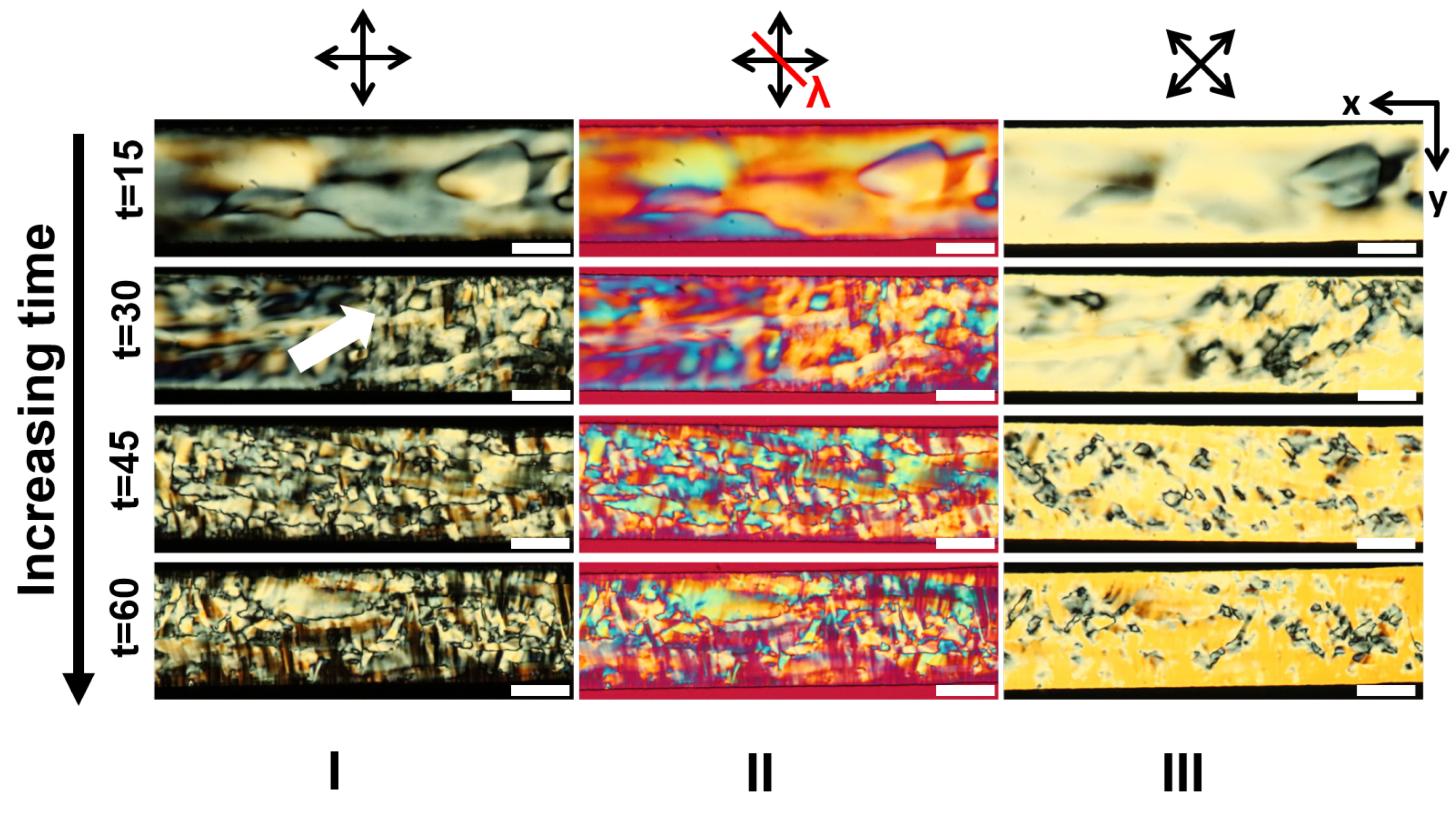
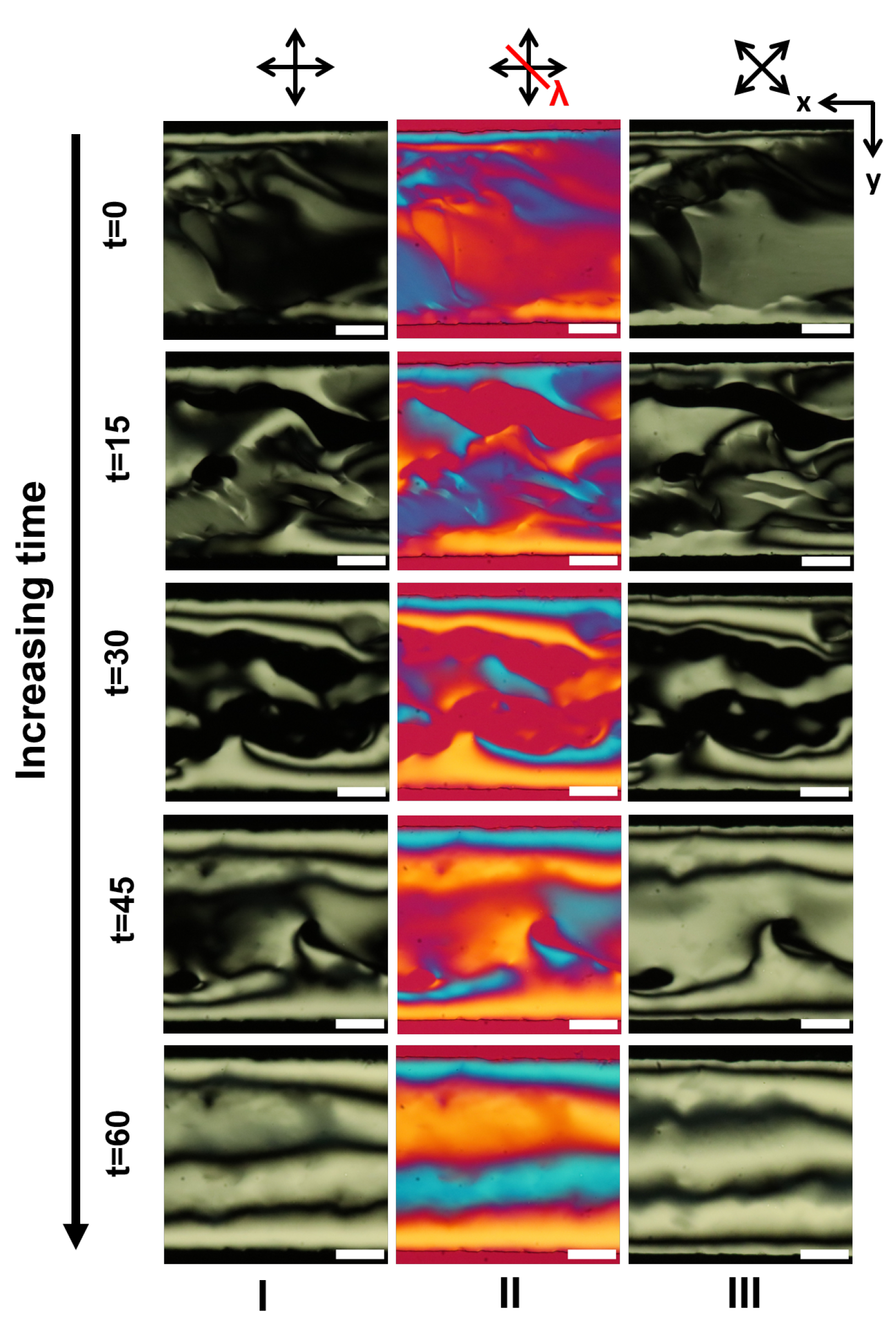
3.2. LCLC Texture in Homeotropic Microchannels

We explored the surface treatment with silanes as a way to modify the surface of PDMS-glass microchannels that support homeotropic anchoring. DMOAP-treated microchannels (prepared freshly) were filled with 14 wt.% DSCG solution in the isotropic phase, sealed, and then allowed to cool down to 22 ° C, maintaining a steady ramp rate of 1.5 ° C per minute, as reported previously for the plasma-treated glass-PDMS microchannels. Figure 6 presents the LCLC textures of the 14 wt.% DSCG solution within homeotropic PDMS-glass microchannels, formed right after the isotropic to nematic transition. The non-zero birefringence patterns suggest that, within the homeotropic channels, the DSCG molecules self-organize into uniformly aligned planar or tilted domains of DSCG columns over the observed time window.
By capturing the evolution of the textures over time, we observe that, initially, the LCLC textures formed within channels with homeotropic anchoring resemble the texture formed within channels with degenerate planar anchoring. We call this as the pseudo planar texture, arising due to the planar or tilted organization of the DSCG discotic stacks in the nematic phase. This is in contrast to the thermotropic nematic textures under homeotropic boundary conditions: here, the polarized light undergoes complete extinction upon passing through the sample, thus appearing completely dark regardless of the polarizer orientation. As observed in the degenerate planar case (previous section), for the homeotropic channels as well, we observe isolated microscale domains of the M-phase nucleation, however at a slower rate than that under the planar conditions. Once formed, the domains propagate through the channel, filling it up completely within about 60 min (Figure 7).
The DSCG M-phase under homeotropic conditions manifests as the characteristic spherulite texture, whereas within planar microchannels, the M-phase resembles the herringbone texture. These contrasting outcomes—herringbone microfluidic texture in degenerate planar and spherulite texture in homeotropic boundary conditions—suggest that the anchoring conditions play a key role in establishing the equilibrium LCLC textures, in absence of flows, within PDMS-glass microfluidic confinements. Nazarenko and coworkers showed a weak homeotropic anchoring on hydrophobic silane-treated substrates [23], which eventually, at a later time, transitioned from homeotropic to planar anchoring, while Tone et al. reported that use of silane to get homeotropic alignment, which does not work on glass LC cells [24]. From the textural evolution shown in Figure 6, it can be deduced that the emergent pseudo planar DSCG texture is in contrast with the typical homeotropic alignment of thermotropic LCs within similar DMOAP-treated channels (the silane DMOAP induces homeotropic surface anchoring). Furthermore, the areas with homeotropic textures were found to be unstable, and as presented using the time lapse sequence in Figure A22, the texture changes spontaneously from the pseudo planar to the spherulite texture.

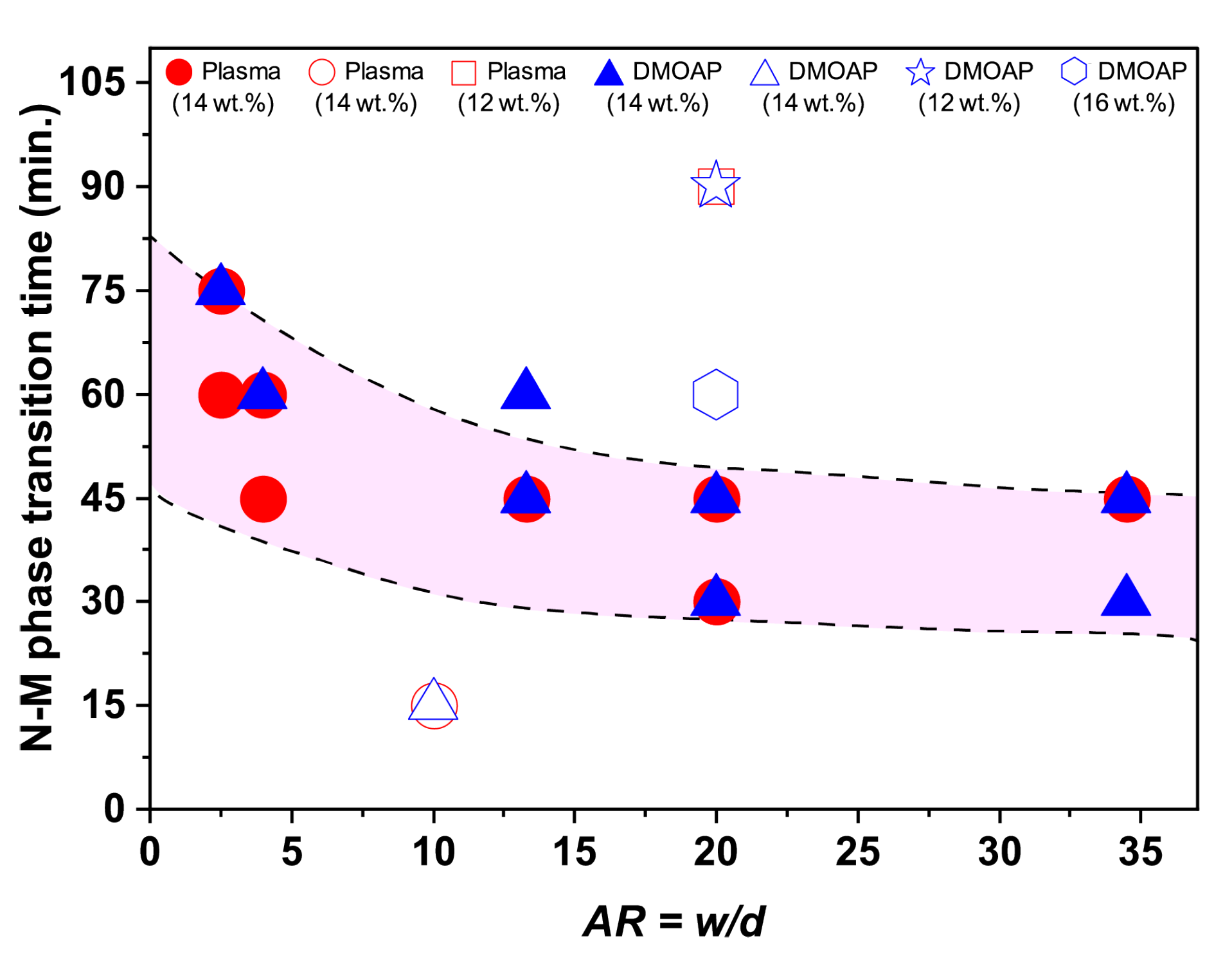
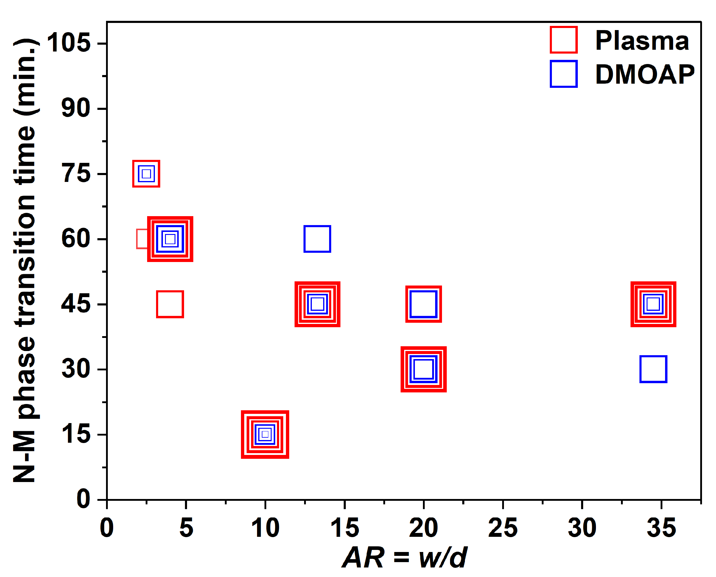
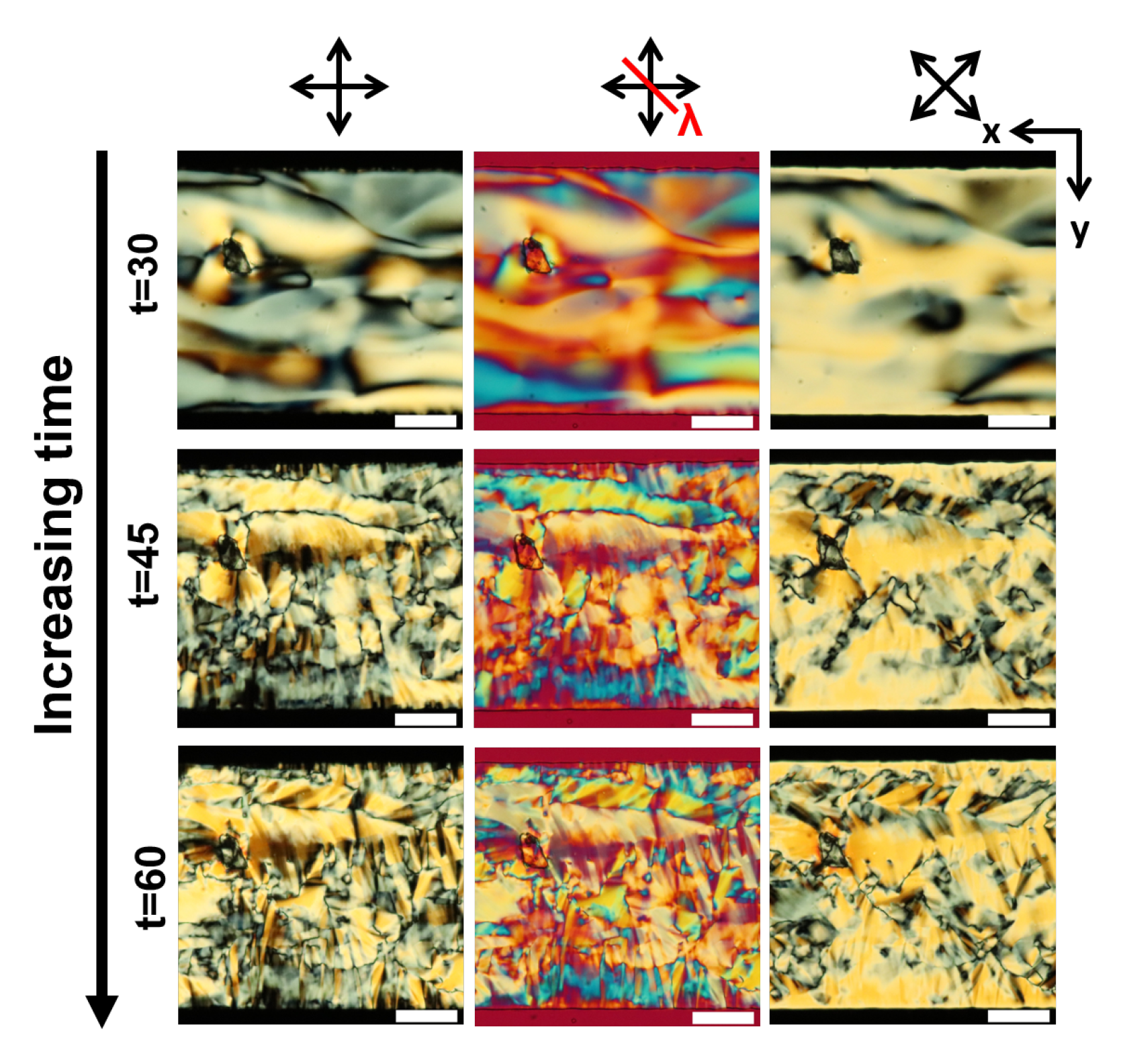
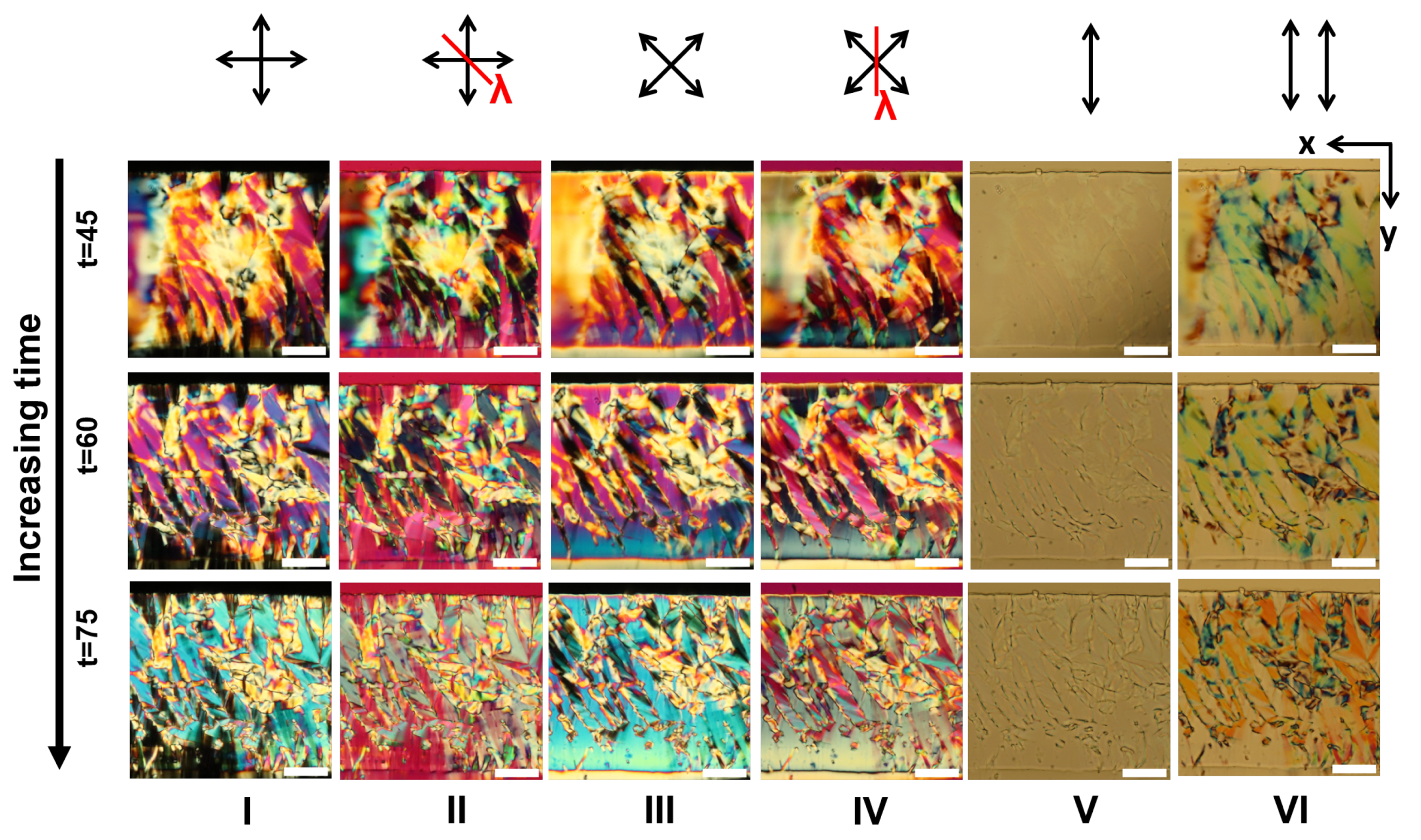
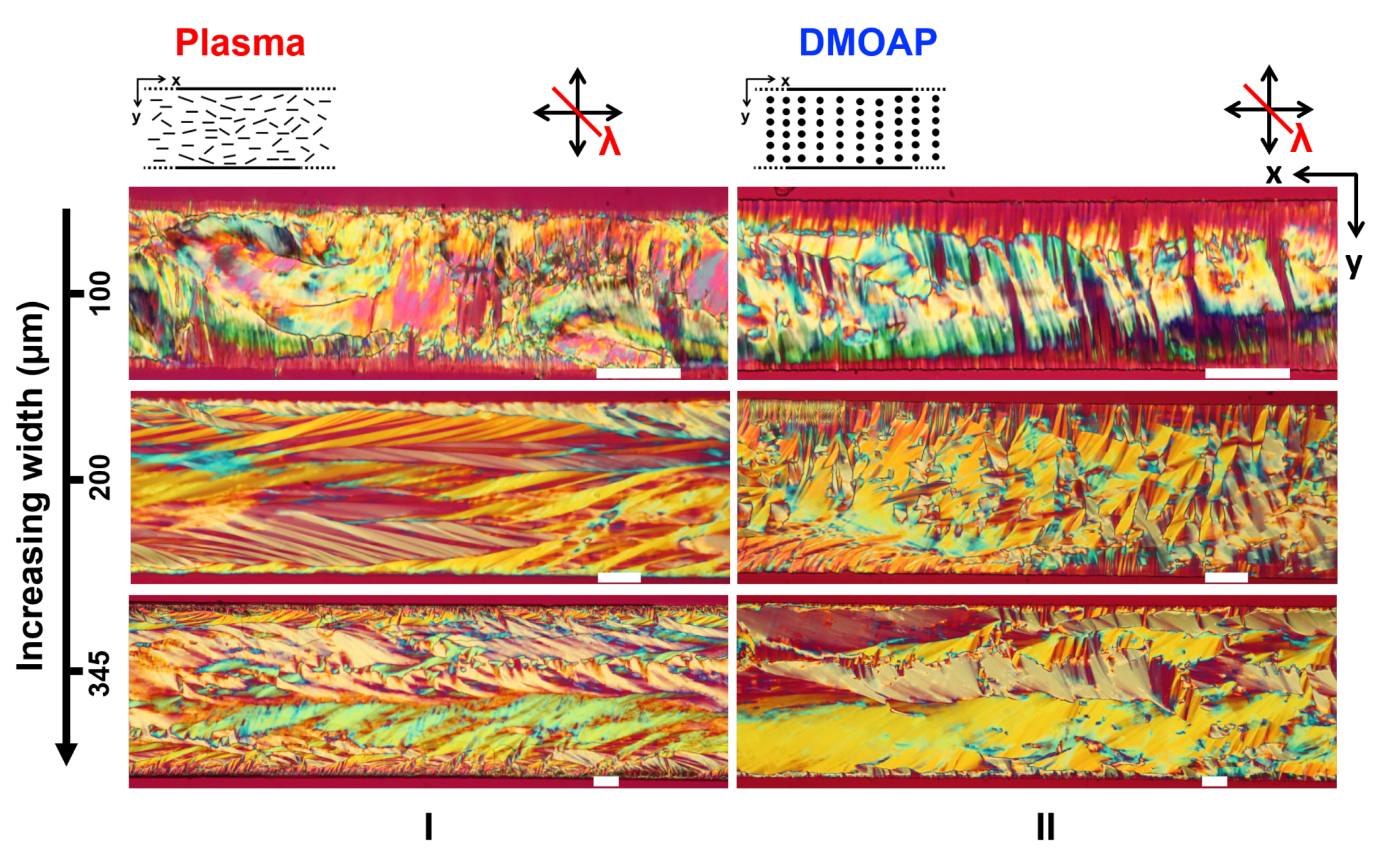
3.3. Role of the Channel Dimensions on the Evolution of the LCLC Textures

The role of microfluidic dimensions was investigated by varying the channel aspect ratio: the ratio between the channel width, w, and the channel depth, d ( A R = w / d ). We studied the texture evolution by systematically varying both the channel width and depth, through the following combinations of w × d (all dimensions in micrometers): (i) variation of width (in μ m): 100 × 10, 200 × 10, and 345 × 10; and variation of depth (in μ m): 100 × 10, 100 × 25, and 100 × 40.

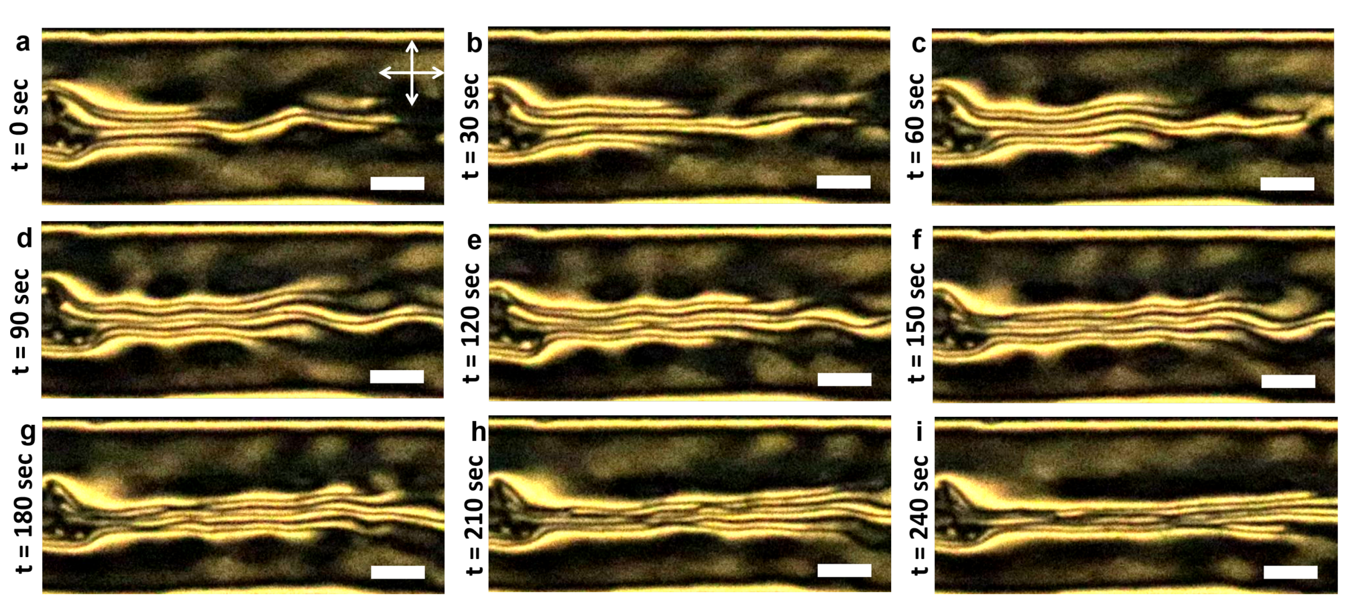
3.3.1. Role of the Channel Width

The role of channel width was investigated by studying two additional dimensions: 200 μ m and 345 μ m, while keeping the depth fixed at 10 μ m. All other experimental conditions and parameters were kept similar to those in the experiments with the 100 μ m wide channels. As described earlier, the stability of the degenerate planar anchoring was checked every 15 min after the cooling ramp concluded (this coincided with the first appearance of the birefringent domains). For both the 200 μ m and 345 μ m wide microchannels, the observations lasted up to 60 min (or slightly longer, as the case was in a few instances), till the equilibrium LCLC static texture was observed, i.e., no further change in the overall pattern and birefringence. Figure 8 presents the POM micrographs of the 200 μ m wide, 10 μ m deep microchannels possessing degenerate anchoring conditions.
Initially, we observed the expected planar texture of DSCG due to the degenerate planar anchoring conditions on the channel walls. The planar microdomains, signifying different orientations of the DSCG discotic stacks in the nematic phase, gave way to the nucleation of a more ordered two-dimensional lattice of the M-phase herringbone texture. Starting from a degenerate alignment (Figure 8), the herringbone texture proliferated along the channel length and, over a timescale of about 60 min, covered the entire channel (shown in Figure 5). It might be worth noting that the herringbone texture manifests a global orientation parallel to the length of the microchannel: this suggests that under degenerate planar anchoring conditions, the microfluidic geometry underpins the emergent textural anisotropy of the confined DSCG. Figure A18I captures the variation of the textural anisotropy with the dimensions of microchannels possessing degenerate planar anchoring. The herringbone texture was found to be most pronounced within the 200 μ m × 10 μ m channels.
On increasing the width to 345 μ m, as shown in Figure A3, we observed the textural transition from Schlieren to herringbone texture consistently; however, for wider channels, the transition occurs over a shorter timescale. The overall dependence of the transition time on channel width (and the aspect ratio) is summarized in Figure 9; a physical basis of the same will be reported elsewhere [55].
Moving from degenerate planar to homeotropic anchoring conditions, the texture initially appears patchy (Figure A4), with complete extinction of the polarized light, a characteristic signature of homeotropic anchoring. Over a time span of about 15 min, the patchy homeotropic domains gradually transformed into the pseudo planar texture, as shown in Figure A4 for the 200 μ m × 10 μ m DMOAP-treated microchannel. Finally, the planar texture transforms into the M-phase, over a timescale of 30 min. Apart from the textures observed in area of the microchannel as shown in Figure A4, two other areas of this microchannel were observed: one where the M-phase (Figure A5) first nucleated and the other with a stable homeotropic texture (Figure A6), developed at t = 45 min. For areas where the homeotropic texture developed, on observing between crossed polarizers and the rotation of the sample by 45 ° , the intensity of transmission light remained low. This area with homeotropic alignment further propagated in the microchannel until t = 60 min, but eventually changed to a degenerate planar texture. At another part of the microchannel where the M-phase appeared at t = 30 min (Figure 7), the observed area completely changed to the M-phase after 45 min. On changing the channel width further to 345 μ m (Figure A7 and Figure A8), qualitatively, we observed the same trend: regions of low intensity of transmitted light were first observed, which then transformed into pseudo planar (within t = 15 min), which eventually changed to the M-phase at t = 45 min. It may be worthwhile to repeat here that, under homeotropic boundary conditions, the M-phase is distinct from that within degenerate planar microchannels: in homeotropic channels, the spherulite texture stretches transversely across the channel width, whereas within the degenerate planar channels, the herringbone structure organizes along the channel length (Figure A18). Taken together, these observations indicate that the channel geometry and surface anchoring, together, play a central role in the development of the static LCLC textures within PDMS-glass devices. In the next section, we report the effect of the channel depth on the textural attributes.

3.3.2. Role of the Channel Depth

The effect of the channel depth was studied using microchannels with d = 25 μ m and 40 μ m, while maintaining the channel width w = 100 μ m. The time evolution of the DSCG textures obtained for plasma-treated microchannels of depth 25 μ m and 40 μ m are shown in Figure A9 and Figure A10; while Figure A11 and Figure A12 capture the effect of the depth in homeotropic channels. On increasing the depth by 150% (i.e., from 10 μ m to 25 μ m deep), the M-phase appeared between 45 and 60 min, whereas on increasing the depth by 300% (100 μ m wide, from 10 μ m to 40 μ m deep), the M-phase appeared between 60 and 75 min. Thus, the appearance of the M-phase, and hence, the nematic to M-phase transition, is retarded due to the increase in the microchannel depth. For the DMOAP-treated microchannels (homeotropic anchoring), the time evolution of the textures are shown in Figure A13 and Figure A14, respectively. Here also, the transition time scale is stretched, relative to the control case (d = 10 μ m): the M-phase appears at about 60 min within the 100 μ m wide, 25 μ m deep channel; while no phase change was captured within the first 60 min within the 40 μ m deep channel. Thus, an increment in the channel depth counters the effects of the increment of the channel width: the two opposing effects can be effectively captured in terms of the channel aspect ratio ( A R = w/d). A careful choice of the aspect ratio should allow us to harness the trade-off between the transition timescales for tuning the nematic to M-phase transitions within microfluidic geometries.
Once LCLC textures stabilized within the channels, we observed qualitative differences in their appearance due to variations in the channel depths. The general features of respective textures are however detectable in both shallow and deeper channels, as shown in Figure A15 and Figure A16 (for planar anchoring) and in Figure A17 (for homeotropic anchoring). Overall, the DSCG textures change from a uniform to a non-uniform appearance with the increase in the channel depth from 10 μ m to 40 μ m, for both the degenerate (Figure A11) and the homeotropic (Figure A14) boundary conditions. Based on the above results, we concluded that the stability of the nematic and M-phase textures, and the transitions therein, depends on the channel dimensions and the surface anchoring conditions. Furthermore, the depth of the microchannel regulates the uniformity of the emergent textures: the lower the depth (i.e., stronger confinement), the more uniform is the stabilized texture, whereas within deeper channels, the textures become increasingly non-uniform, possibly due to increased bulk effects (due to relatively weak surface effects). Additionally, we used two other DSCG concentrations for our experiments: 12 wt.% (closer to the isotropic phase at the operating temperature) and 16 wt.% (closer to the M-phase) and studied the POM textures 200 μ m wide and 10 μ m microchannels. As shown in Figure 10 (I–IV), initially, no microfluidic texture was detected at 12 wt.% DSCG, under both degenerate planar and homeotropic boundary conditions. This is due to the presence of a high proportion of the isotropic phase in the DSCG solution. Then, between 45 and 60 min, planar nematic textures emerged, which at about 90 min changed to the M-phase texture. The sequence of isotropic-nematic-M-phase transition confirms the gradual increase of the DSCG concentration within the microfluidic environment. At 16 wt.%, within the DMOAP-treated microchannel (V–VI), a patchy homeotropic domain was observed (with regions of total light extinction), while the rest of the regions were birefringent, which ultimately transformed to the M-phase at around 60 min.

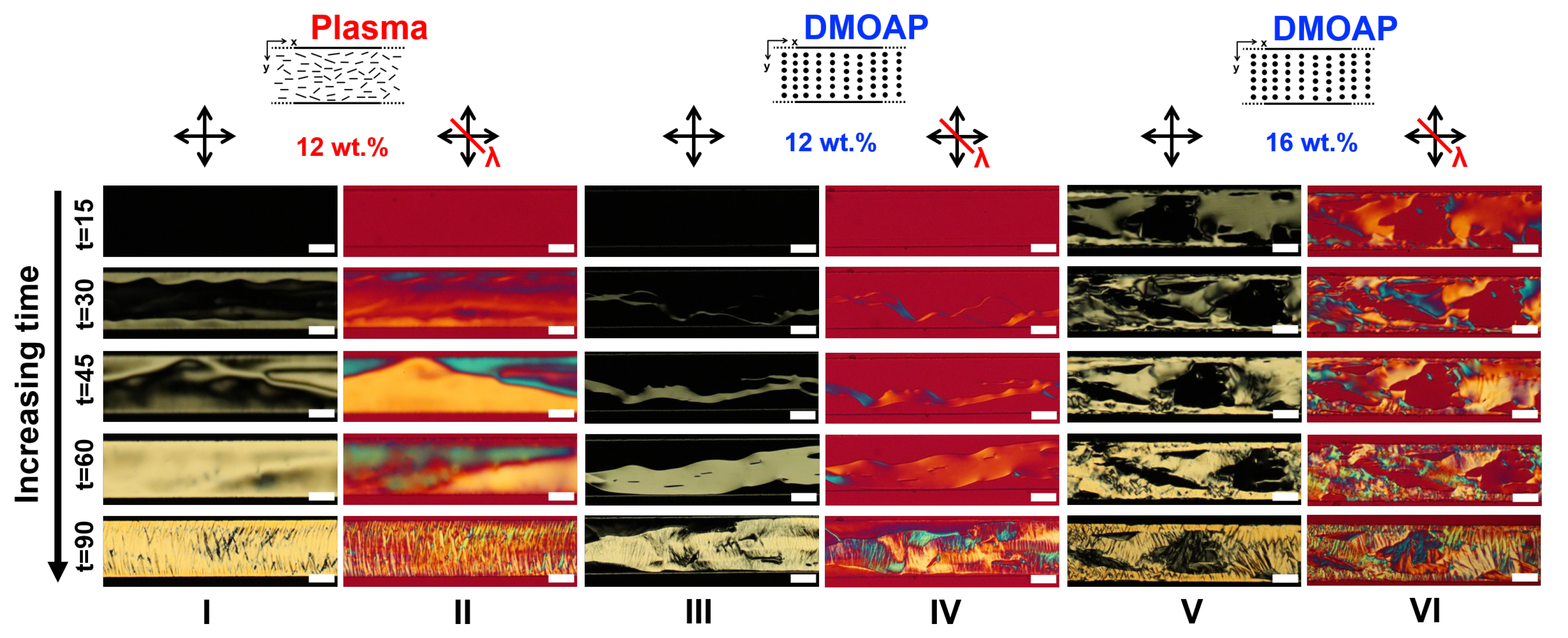
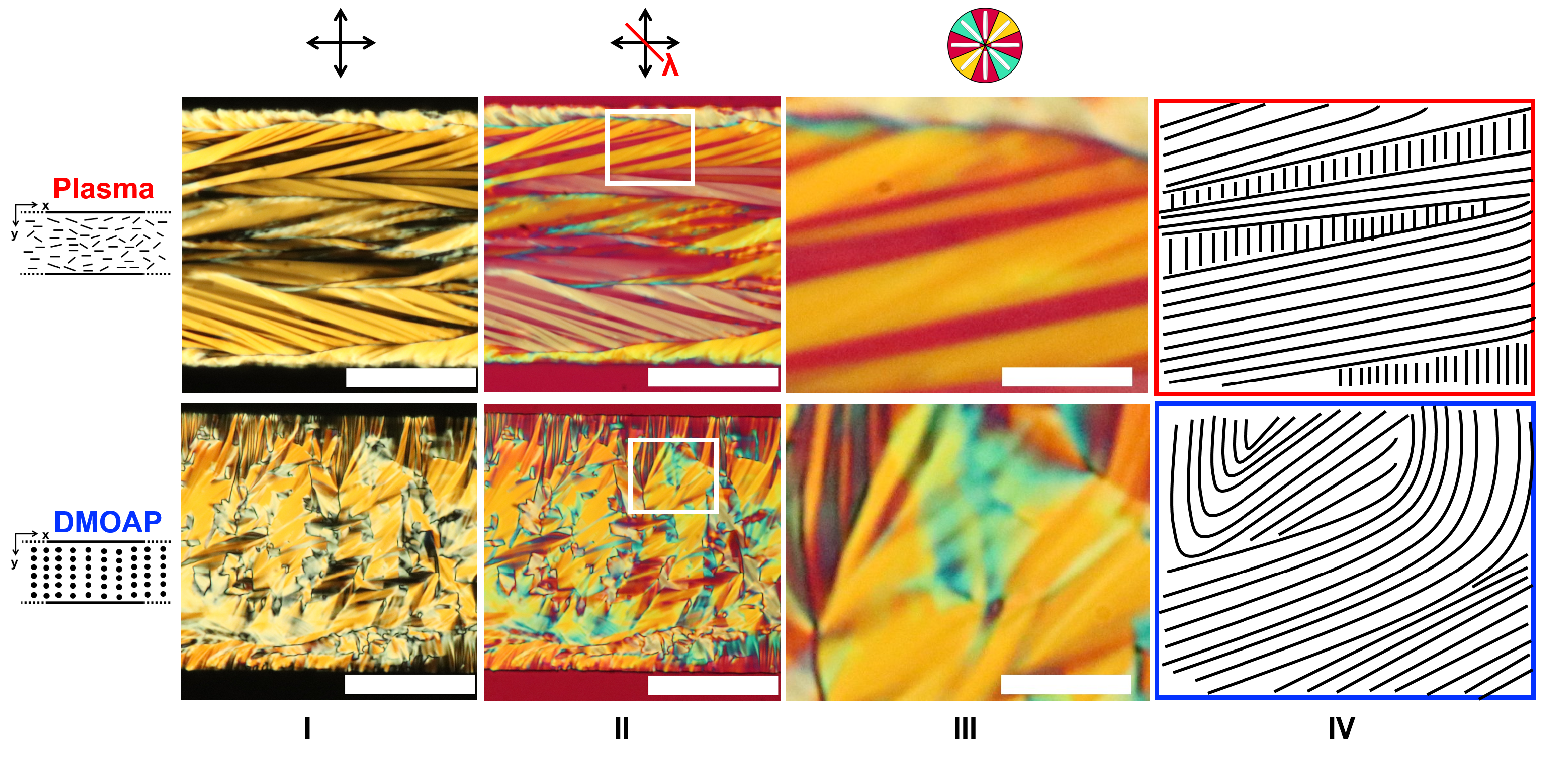
3.4. Comparing the Effects of Surface Treatment on the Stable LCLC Microfluidic Textures

Figure 11 and Figure A18 present a comparative analysis of the M-phase texture developed in PDMS-glass microchannels, under both plasma (degenerate planar) and DMOAP (homeotropic) surface treatments. For the microchannels with plasma treatment, the M-phase yields the herringbone texture, with an overall structural orientation along the channel length. For the DMOAP-treated microchannel, the M-phase elicits the spherulite texture, which aligns perpendicular to the channel walls, i.e., along the transverse direction (Figure 11 and Figure A18). As indicated by the contact angle measurement of the 14 wt.% DSCG solution (Figure 1, Panels f and g), plasma exposure renders both PDMS and glass surfaces hydrophilic, whereas the silane, DMOAP, makes the surface hydrophobic. Consequently, the nucleation, growth, and propagation of the textures will be locally influenced by the nature of the boundary conditions. In the planar case, the discotic stacks in the nematic or M-phase are expected to align along the planar domains imposed by the plasma treatment. This, with the additional constraint from the long axis of the microchannel, guides the herringbone structure along the channel length. For the homeotropic case, the spherulite texture emerges due to the normal alignment of the discotics on the channel surfaces and is thus constrained to grow from the ceiling to the floor and from wall-to-wall of the microchannel. Thus, we do not see any structural bias along the channel length.

3.5. Discussions

In order to gain qualitative insights into the textural transitions, we looked into the impact of air plasma and DMOAP treatments on the PDMS surface morphology. It has been known that plasma treatment of the PDMS surface causes nano-structuring of PDMS and increases the water contact angles depending on the duration and intensity of the plasma treatment used [60,61,62,63]. Bodas et al. showed the notable cracks (through SEM) of the PDMS upon 150 W, 15 min, plasma treatment [60]. On the other hand, Hillborg et al. employed 40 W, 3 min, plasma treatment and observed insignificant surface morphological changes (through SEM and AFM) [63]. From the surface hydro-philicity/-phobicity angle (a surface parameter modified reproducibly by air plasma exposure of glass and PDMS), Ruben et al. reported enhanced capillary flow within PDMS microchannels that were hydrophilic [64]. Complementarily, from a membrane perspective, hydrophobic species, depending on the molecular size, can permeate readily through PDMS [65,66]. Since DSCG is a bulkier molecule with a much higher solubility value (195.3 mg/mL [67]) compared to small molecules like quinine or Nile red, we could rule out the possibility of DSCG permeation in PDMS. On the other hand, hydrophilized PDMS surfaces (after plasma exposure) would enhance the permeation of water molecules through PDMS; hydrophobic PDMS (native or DMOAP-treated) will hinder the permeation of water molecules. Consequently, depending on the surface treatment used in our experiments (plasma vs. DMOAP), we expect water uptake by the PDMS surfaces to vary. Consequently, this impacts the timescales over which the water molecules disappear from the DSCG solution, triggering an increase in the local DSCG concentration, ultimately pushing the solution closer to the nematic to M-phase transition. Once the M-phase nucleates locally, it propagates through the channel thereafter as more water molecules permeate into the PDMS over time. However, the rate at which the water molecules enter PDMS is determined by the surface hydro-philic/-phobic characteristics. The experimental timescales of the nematic-M-phase transition in our study confirm this and that the surface properties along with geometric dimensions mediate the textural dynamics of LCLC solutions under static conditions.
It is evident from the time dependent optical observations that the nematic phase of 14 wt.% DSCG, within both plasma- and DMOAP-treated microchannels, exhibited a phase transition from the nematic to the more ordered columnar M-phase. It is known that the M-phase occurs at a higher concentration of DSCG, and for a nematic-M-phase transition to occur from a nematic phase, there has to be a change in the concentration of DSCG (unless the temperature of the environment changes, which in our experiments was kept fixed). The DSCG concentration can change either by the variation of the temperature or due to the loss of water from the solution. As all measurements were done at a constant temperature, in evaporation-proof microfluidic devices, the change in the initial concentration of the DSCG solution has to come from the loss of water due to permeation into PDMS. To confirm that the nematic to M-phase transition results due to the permeation of water molecules into the PDMS, we compared the stability of the DSCG textures (for the 14 wt.% DSCG solution) within glass capillaries, for both native and DMOAP-treated samples. As shown in Figure A19 and Figure A20, for untreated glass capillaries (weakly homeotropic) and DMOAP-treated glass capillaries (strong homeotropic anchoring), respectively, the textures for degenerate planar and homeotropic alignment were observed. The time dependent texture analysis did not reveal the nematic to M-phase transition, regardless of the surface treatment, thus confirming the role of PDMS surfaces in taking up water molecules. Furthermore, we studied the nematic phase of the 14 wt.% DSCG solution by keeping one end of the glass capillary open to allow the evaporation of water. The time evolution of texture showed an increase in the birefringence, indicating a transition to a more ordered phase, though no herringbone M-phase texture was observed due to the weakly homeotropic conditions within the native capillaries (Figure A21). The above combination of control tests confirms that the M-phase development within the PDMS-glass microchannels is mediated by the surface attributes of PDMS, which is currently being investigated further.
We studied the 12 wt.% DSCG solution in a plasma-treated PDMS-glass microchannel Figure A22. As this concentration is close to the isotropic-nematic phase transition temperature (see the phase diagram in Figure 1), one should expect that the system has to first reach a concentration of DSCG that shows a stable nematic phase, and then, the N-M-phase transition follows. We filled a plasma-treated PDMS-glass microchannel with the 12 wt.% solution and sealed it, then as discussed previously, we carried out the POM time lapse imaging (imaged every 30 s). As hypothesized, initially, the system was observed to be in the isotropic phase, with the nematic phase emerging after about 25 min. Thereafter, the system stayed in the nematic phase for about 255 min, before the M-phase finally appeared. This confirmatory test consolidates our conclusions that the surface properties of PDMS induces systematic changes in the initial concentration of DSCG, which ultimately lead to the formation of the spontaneous, yet tunable, LCLC phase transitions. A detailed quantitative analysis of the surface-mediated phase transition will be discussed elsewhere [55].

4. Conclusions

We exploit a simple and flexible soft lithography technique to create PDMS-glass microfluidic devices for studying the nucleation, growth, and stability of LCLC textures. The temporal study carried out here reveals the spontaneous (and unexpected) emergence of M-phase textures, with DSCG solutions that are originally in the nematic phase. Our comprehensive polarization optical study demonstrates that the static LCLC microfluidic textures, within standard PDMS-glass microfluidic devices, are far from trivial due to their dependence on the following key parameters:
(i)
microchannel dimensions (confinement effect),
(ii)
surface anchoring (anchoring effects, specifically in relation to the PDMS surface), and
(iii)
experimental timescale (spontaneous surface-mediated effects).
The three fundamental variables determine the local and temporal no-flow LCLC microfluidic textures, giving us a set of key experimental parameters which could be potentially employed to register the initial conditions for microfluidic flow experiments.
Table 1 summarizes the textural manifestations of DSCG solutions in PDMS-glass microchannels and the timescales over which various surface-induced phase transitions occur. Multiple experimental replicates confirm the reproducibility of the values included in Table 1, for a range of aspect ratios ( w / d ) of channels possessing either degenerate planar or homeotropic boundary conditions (Figure 9). Although plasma treatment of microchannels successfully imposed degenerate planar conditions (for both the thermotropic and LCLC nematic phase), the DMOAP treatment, used frequently to generate homeotropic alignment, failed to have a similar effect on DSCG solutions at 12 and 14 wt.% concentrations. However, at 16 wt.%, we observed larger homeotropic patches (leading to a higher cumulative area showing homeotropic texture), with longer temporal stability. We conclude that silane derivatives (e.g., DMOAP), usually employed for generating homeotropic alignment for thermotropic LCs, may not be as effective for inducing normal surface anchoring of the LCLCs within PDMS-glass devices. Based on a previous report by Tone et al., both hydrophobicity and chemical affinity could play a role in inducing homeotropic alignment. Here, materials with low surface energy—without alkyl chains—could be considered as suitable alternatives to generate homeotropic alignment, for instance polybutadiene and styrene-butadiene-styrene [24]. These materials can work for glass devices; however, there are a few technical hurdles in coating PDMS-glass microchannels with these materials, primarily due to the dissolution step (with organic solvents), which can cause swelling of the PDMS, thereby modifying the microfluidic geometry.
The key and the most striking result of this work as summarized in Figure 9 and Figure A1 is the temporal variation of lyotropic textures induced by a spontaneous phase transition from the nematic to the M-phase. The time of first appearance of the M-phase varied inversely with the channel aspect ratio ( A R = w / d ). This trend was most pronounced in the 14 wt.% sample. By changing the channel dimensions, surface anchoring, and the concentration of the LCLC material, we could systematically tune both the nature of the characteristic texture and the temporal dynamics of the nematic to M-phase transition. Additionally, the texture of the M-phase depended on the surface anchoring conditions: herringbone texture under degenerate planar conditions; and spherulite texture under homeotropic conditions. Furthermore, both herringbone and spherulite textures manifested global orientations: while the herringbone texture was oriented along the channel length, the spherulite texture was oriented perpendicular to the channel length (in the transverse direction). The temporal dynamics of the nematic to M-phase transition and the final M-phase texture (stable over a long time) could be controlled by varying the aspect ratio or, independently, the channel width and the depth. Our straightforward strategy to employ LCLC self-organization within a soft-lithography-based microfluidic platform considerably widens the scope of LCLCs, for both applied and fundamental research, and sets the stage for future studies on the flow behavior LCLCs in strict microfluidic environments. Interestingly, even the static no-flow textures hold promising prospects for potential applications in LCLC-mediated transport processes, for instance, in regulating the anisotropic diffusion coefficients locally over time.
As shown through the time lapse image sequence in Figure 12, defect lines near a microscale inclusion (the channel and inclusion were DMOAP-treated) can transition over time—purely due to surface-mediated effects—thereby triggering microscale transport, even in absence of external pressure gradients [55]. Investigations on the dynamics of LCLCs under flow within PDMS-glass microfluidic devices is currently underway and can be extended to other systems to study surface-mediated phase transitions, for instance in water-based lyotropic liquid crystals systems such as peptides, liquid crystal polymers, and viruses. The temporal stability of textures can result in significant real-world applications, in particular to capture the dynamics of in biological systems, where transport processes can respond to (or be modulated by) the compliance, surface, and morphological attributes of the system.

Author Contributions

A.S. (Anshul Sharma) and A.S. (Anupam Sengupta) designed the research, performed the experiments, and analyzed data. All authors interpreted the data and wrote the paper. All authors have read and agreed to the published version of the manuscript.

Funding

This work was supported by the ATTRACT Investigator Grant to A.S.G. (Grant Number: A17/MS/ 11572821/MBRACE) of the Luxembourg National Research Fund.

Institutional Review Board Statement

Not applicable.

Informed Consent Statement

Not applicable.

Data Availability Statement

For all supporting data, contact the corresponding author or refer to the Appendix A.

Acknowledgments

The authors thank the Luxembourg National Research Fund for supporting this work through the ATTRACT Investigator Grant (to A.S., Grant Number: A17/MS/ 11572821/MBRACE), and are grateful to M.G. Mazza, A. Ghoshal, and J. Dhar for valuable discussions during the course of this work.

Conflicts of Interest

The authors declare no conflict of interest.

Appendix A. Supplementary Figures

Figure A1. Dependence of the nematic to M-phase transition time on the channel aspect ratio, shown here for the experimental replicates covered in this study (34 replicates for 14 wt.% DSCG concentration, under both plasma and DMOAP surface treatments). Red squares indicate degenerate planar data, while blue squares represent homeotropic data. For t = 15 min and AR = 10, the plot shows 3 overlying data points for plasma (red square), and 3 overlying data points for DMOAP (blue square); for t = 30 min and AR = 20, 2 overlying data points are shown for plasma (red square), and 2 overlying data points for DMOAP (blue square); for t = 45 min and AR = 13.3, the plot shows 3 overlying data points for plasma (red square), and 2 overlying data points for DMOAP (blue square); for t = 45 min and AR = 20, the plot shows 1 overlying data points for plasma (red square), and 1 overlying data point for DMOAP (blue square); for t = 45 min and AR = 34.5, the plot shows 3 overlying data points for plasma (red square), and 2 overlying data points for DMOAP (blue square); for t = 60 min and AR = 2.5, the plot shows single data point for plasma (red square); and AR = 4, the plot shows 2 overlying data points for plasma (red square), and 2 overlying data points for DMOAP (blue square); and for t = 75 min and AR = 2.5, the plot shows 2 overlying data points for plasma (red square), and 2 overlying data points for DMOAP (blue square).
Crystals 11 00035 g0a1
Figure A2. Optical micrographs of menisci within glass capillaries (viewed horizontally under microscope) with dimensions 100 μ m × 1000 μ m (cross-section dimensions), without any treatment: (a) Water; (b) 5CB (filled in nematic phase). Optical micrograph of glass capillary after DMOAP treatment: (c) water and (d) 5CB (filled in isotropic phase). Scale bar: 500 μ m.
Crystals 11 00035 g0a2
Figure A3. Degenerate planar anchoring within wider channels, here using 345 μ m wide, 10 μ m deep microfluidic device. The transition to herringbone texture is accelerated in wider channels, as captured by the time lapse imaging with polarizers at various configurations: (I) between crossed polarizers; (II) crossed polarizers with the λ -plate; (III) crossed polarizers with channel at 45 ° relative to the polarizer. Here, time (t) is in minutes after the cooling ramp is completed. Scale bar: 50 μ m.
Crystals 11 00035 g0a3
Figure A4. LCLC microfluidic textures in 200 μ m wide, 10 μ m deep microchannels treated for homeotropic anchoring. The textural evolution was observed over time, using polarizing optical microscopy. The configuration of the polarizer and λ -retardation plate are presented at the top of each image. Here, time (t) is in minutes after cooling ramp is concluded. (IIII) shows the POM micrographs obtained from a combination of different polarizer orientations at the corresponding time. Scale bar: 50 μ m.
Crystals 11 00035 g0a4
Figure A5. Long-term textures in 200 μ m wide, 10 μ m deep microchannels treated for homeotropic anchoring. The nucleation and propagation of M-phase can be observed here, imaged between polarizers under different configurations as described above. Here, time (t) is in minutes after cooling ramp is concluded. Scale bar: 50 μ m.
Crystals 11 00035 g0a5
Figure A6. Patchy homeotropic anchoring in certain regions within the DMOAP treated 200 μ m wide, 10 μ m deep microchannel, with 14 wt.% DSCG solution. The textures were stable over long timescales, observed here between polarizers under different configurations, as described above. Here, time (t) is in minutes after cooling ramp is concluded. (IIII) shows the POM micrographs obtained from a combination of different polarizer orientations at the corresponding time. Scale bar: 50 μ m.
Crystals 11 00035 g0a6
Figure A7. LCLC textures within wider channels possessing homeotropic anchoring, here within 345 μ m wide, 10 μ m deep microchannel, leading to the pseudo planar texture (14 wt.% DSCG). Overall, the texture resembled that of planar or tilted orientation. Imaging details are noted at the top of each image. Here, time (t) is in minutes after cooling ramp is concluded. (IVI) shows the POM micrographs obtained from a combination of different polarizer orientations at the corresponding time. Scale bar: 50 μ m.
Crystals 11 00035 g0a7
Figure A8. Gradual formation of the spherulite texture within DMOAP treated microchannel (345 μ m wide, 10 μ m deep), with 14 wt.% DSCG. Imaging started at 30 min after the end of the cooling ramp, and lasted till 60 min: (I) between crossed polarizers; (II) crossed polarizers and λ -plate; (III) crossed polarizers at 45 ° relative to channel length; (IV) under crossed polarizers with 45 ° rotation and λ -plate; (V) with only analyzer and (VI) analyzer parallel to the polarizer, with both perpendicular to the channel length. Here, time (t) is in minutes after cooling ramp is concluded. Scale bar: 50 μ m.
Crystals 11 00035 g0a8
Figure A9. Degenerate planar anchoring-(100 μ m wide, 25 μ m deep)-14 wt.% DSCG. Evolution of textures exhibited as a function of time under various configurations of the polarizers. Polarizing optical micrographs show the top view of the channel from t = 0 to 75 min, images were taken as per the scheme discussed in the previous images. Here, time (t) is in minutes after ramp is completed. (IIII) shows the POM micrographs obtained from a combination of different polarizer orientations at the corresponding time. Scale bar: 50 μ m.
Crystals 11 00035 g0a9
Figure A10. M-phase texture in 100 μ m wide, 25 μ m deep microchannel. Evolution of textures exhibited as a function of time under various conditions. Polarizing optical micrographs showing the top view of the channel from t = 60 to 75 min. Evolution of textures under crossed polarizers; images were taken as per the scheme discussed in the previous images. Here, time (t) is in minutes after ramp is completed. (IIII) shows the POM micrographs obtained from a combination of different polarizer orientations at the corresponding time. Scale bar: 50 μ m.
Crystals 11 00035 g0a10
Figure A11. Degenerate planar anchoring textures in 100 μ m wide, 40 μ m deep channel. Evolution of textures as a function of time under various polarizer configurations, as described in previous images. Here, time (t) is in minutes after cooling ramp is concluded. (IVI) shows the POM micrographs obtained from a combination of different polarizer orientations at the corresponding time. Scale bar: 50 μ m.
Crystals 11 00035 g0a11
Figure A12. Long-term textures in 100 μ m wide, 40 μ m deep channels. The absence of the well-aligned herringbone texture, under degenerate planar boundary conditions, suggests that the textural transitions are hindered within d e e p e r channels. Here, time (t) is in minutes after cooling ramp is concluded. (IVI) shows the POM micrographs obtained from a combination of different polarizer orientations at the corresponding time. Scale bar: 50 μ m.
Crystals 11 00035 g0a12
Figure A13. Effect of the channel depth on the DSCG texture, here observed within 100 μ m wide, 25 μ m deep microchannel possessing homeotropic anchoring conditions. The concentration of DSCG was 14 wt.%. Polarizing optical micrographs were taken using same configuration of polarizers and λ -plate, as described previously. Here, time (t) is in minutes after cooling ramp is concluded. (IVI) shows the POM micrographs obtained from a combination of different polarizer orientations at the corresponding time. Scale bar: 50 μ m.
Crystals 11 00035 g0a13
Figure A14. Loss of textural uniformity upon increasing the channel depth, here observed within 100 μ m wide, 40 μ m deep microchannel, for the 14 wt.% DSCG. Time (t) is in minutes after cooling ramp is concluded. (IVI) shows the POM micrographs obtained from a combination of different polarizer orientations at the corresponding time. Scale bar: 50 μ m.
Crystals 11 00035 g0a14
Figure A15. DSCG textures within 200 μ m wide, 15 μ m deep microchannel possessing degenerate planar anchoring, here observed with 14 wt.% DSCG. Here, time (t) is in minutes after cooling ramp is concluded. (IVI) shows the POM micrographs obtained from a combination of different polarizer orientations at the corresponding time. Scale bar: 50 μ m.
Crystals 11 00035 g0a15
Figure A16. Degenerate planar anchoring within 200 μ m wide, 15 μ m deep microchannel yields M-phase textures at 14 wt.% DSCG. Imaging details are described previously. Here, time (t) is in minutes after cooling ramp is concluded. (IVI) shows the POM micrographs obtained from a combination of different polarizer orientations at the corresponding time. Scale bar: 50 μ m.
Crystals 11 00035 g0a16
Figure A17. DSCG textures within 200 μ m wide, 15 μ m deep microchannel possessing homeotropic surface anchoring, here shown for 14 wt.% DSCG. Imaging details are described previously. Here, time (t) is in minutes after cooling ramp is concluded. (IVI) shows the POM micrographs obtained from a combination of different polarizer orientations at the corresponding time. Scale bar: 50 μ m.
Crystals 11 00035 g0a17
Figure A18. Herringbone and spherulite microfluidic textures formed by DSCG under degenerate planar and homeotropic anchoring conditions respectively. The textures corresponding to DSCG M-phase were observed between crossed polarizers with λ -retardation plate. The textures depend on the channel aspect ratio and imposed surface anchoring. (I) Microchannel with degenerate planar anchoring with dimensions: (100 μ m wide, 10 μ m deep), (200 μ m wide, 10 μ m deep) and (345 μ m wide, 10 μ m deep), respectively. Note the structural orientation of the herringbone texture along the channel length. (II) Observation of the spherulite texture in microchannels possessing homeotropic anchoring. The spherulite texture exhibits an overall orientation along the channel transverse direction (wall-to-wall). Scale bar: 50 μ m.
Crystals 11 00035 g0a18
Figure A19. DSCG textures within untreated glass capillaries having weakly homeotropic anchoring. Evolution of textures exhibited by 14 wt.% DSCG in 10 × 100 μ m (depth × width) glass capillary as a function of time. Polarizing optical micrographs show the top view of the channel from t = 0 to 45 min: (I) between crossed polarizers; (II) crossed polarizers with λ -plate and (III) crossed polarizers at 45 ° relative to channel length. Here, time (t) is in minutes after cooling ramp is concluded. No textural transition was observed, and the texture stabilizes to a typical homeotropic appearance (dark appearance between crossed polarizers, independent of the polarizer orientations. Scale bar: 50 μ m.
Crystals 11 00035 g0a19
Figure A20. DSCG textures within DMOAP treated glass capillaries (strong homeotropic anchoring). The texture exhibited by 14 wt.% DSCG in 10 × 100 μ m (depth × width) DMOAP treated glass capillary is stable over time. The POM textures confirm the homeotropic anchoring due to complete extinction of the polarized light (dark appearance). Here, time (t) is in minutes after cooling ramp is concluded. (IIII) shows the POM micrographs obtained from a combination of different polarizer orientations at the corresponding time. Scale bar: 50 μ m.
Crystals 11 00035 g0a20
Figure A21. Evolution of DSCG textures (14 wt.% DSCG) in 40 μ m × 400 μ m untreated glass capillary, open from both sides. The transition from nematic to M-phase could be reproduced by allowing evaporation of water from the original DSCG solution (14 wt.%). The sequence of images follow similar polarization configuration as described throughout the text. Here, time (t) is in minutes after cooling ramp is concluded. (IIII) shows the POM micrographs obtained from a combination of different polarizer orientations at the corresponding time. Scale bar: 100 μ m.
Crystals 11 00035 g0a21
Figure A22. POM time lapse micrographs capture the isotropic-nematic-M phase transition of 12 wt.% DSCG within 200 μ m wide, 10 μ m deep microchannel with degenerate planar anchoring. Clockwise from top-left panel: isotropic phase observed under crossed polarizers with λ -plate inserted (t = 0 min); top-right panel shows crossed polarized micrograph at t = 25 min: faint birefringence is noted, indicating nematic phase; bottom-right panel presents crossed polarized image at t = 255 min, capturing the appearance of the M-phase (right edge of the micrograph); and bottom-left panel at t = 355 min shows the crossed polarized image of the spherulite (M-phase) texture. Here, time (t) is in minutes after cooling ramp is concluded. Scale bar: 100 μ m.
Crystals 11 00035 g0a22

References

  1. Lydon, J. Chromonic review. J. Mater. Chem. 2010, 20, 10071–10099. [Google Scholar] [CrossRef]
  2. Lydon, J. Chromonic liquid crystalline phases. Liq. Cryst. 2011, 38, 1663–1681. [Google Scholar] [CrossRef]
  3. Zhou, S. Recent progresses in lyotropic chromonic liquid crystal research: Elasticity, viscosity, defect structures, and living liquid crystals. Liq. Cryst. Today 2018, 27, 91–108. [Google Scholar] [CrossRef]
  4. Lubensky, T.C. Confined chromonics and viral membranes. Mol. Cryst. Liq. Cryst. 2017, 646, 235–241. [Google Scholar] [CrossRef] [Green Version]
  5. Hartshorne, N.H.; Woodard, G.D. Mesomorphism in the system disodium cromoglycate-water. Mol. Cryst. Liq. Cryst. 1973, 23, 343–368. [Google Scholar] [CrossRef]
  6. Cox, J.S.; Woodard, G.D.; McCrone, W.C. Solid-state chemistry of cromolyn sodium (disodium cromoglycate). J. Pharm. Sci. 1971, 60, 1458–1465. [Google Scholar] [CrossRef]
  7. Agra-Kooijman, D.M.; Singh, G.; Lorenz, A.; Collings, P.J.; Kitzerow, H.S.; Kumar, S. Columnar molecular aggregation in the aqueous solutions of disodium cromoglycate. Phys. Rev. E Stat. Nonlinear Soft Matter Phys. 2014, 89, 062504. [Google Scholar] [CrossRef] [Green Version]
  8. Simon, K.A.; Sejwal, P.; Falcone, E.R.; Burton, E.A.; Yang, S.; Prashar, D.; Bandyopadhyay, D.; Narasimhan, S.K.; Varghese, N.; Gobalasingham, N.S.; et al. Noncovalent polymerization and assembly in water promoted by thermodynamic incompatibility. J. Phys. Chem. B 2010, 114, 10357–10367. [Google Scholar] [CrossRef]
  9. Shiyanovskii, S.V.; Lavrentovich, O.D.; Schneider, T.; Ishikawa, T.; Smalyukh, I.I.; Woolverton, C.J.; Niehaus, G.D.; Doane, K.J. Lyotropic chromonic liquid crystals for biological sensing applications. Mol. Cryst. Liq. Cryst. 2005, 434, 259/[587]–270/[598]. [Google Scholar] [CrossRef]
  10. Guo, F.; Mukhopadhyay, A.; Sheldon, B.W.; Hurt, R.H. Vertically Aligned Graphene Layer Arrays from Chromonic Liquid Crystal Precursors. Adv. Mater. 2011, 23, 508–513. [Google Scholar] [CrossRef] [PubMed]
  11. Mushenheim, P.C.; Trivedi, R.R.; Tuson, H.H.; Weibel, D.B.; Abbott, N.L. Dynamic self-assembly of motile bacteria in liquid crystals. Soft Matter 2014, 10, 88–95. [Google Scholar] [CrossRef] [PubMed] [Green Version]
  12. Zhou, S.; Sokolov, A.; Lavrentovich, O.D.; Aranson, I.S. Living liquid crystals. Proc. Natl. Acad. Sci. USA 2014, 111, 1265–1270. [Google Scholar] [CrossRef] [PubMed] [Green Version]
  13. Collings, P.J.; van der Asdonk, P.; Martinez, A.; Tortora, L.; Kouwer, P.H. Anchoring strength measurements of a lyotropic chromonic liquid crystal on rubbed polyimide surfaces. Liq. Cryst. 2017, 44, 1165–1172. [Google Scholar] [CrossRef]
  14. Lee, H.; Labes, M.M. Lyotropic cholesteric and nematic phaes of disodium cromoglycate in magnetic fields. Mol. Cryst. Liq. Cryst. 1982, 84, 137–157. [Google Scholar] [CrossRef]
  15. Tone, C.M.; De Santo, M.P.; Buonomenna, M.G.; Golemme, G.; Ciuchi, F. Dynamical homeotropic and planar alignments of chromonic liquid crystals. Soft Matter 2012, 8, 8478–8482. [Google Scholar] [CrossRef]
  16. Simon, K.A.; Burton, E.A.; Cheng, F.; Varghese, N.; Falcone, E.R.; Wu, L.; Luk, Y.Y. Controlling thread assemblies of pharmaceutical compounds in liquid crystal phase by using functionalized nanotopography. Chem. Mater. 2010, 22, 2434–2441. [Google Scholar] [CrossRef]
  17. Jeong, J.; Han, G.; Johnson, A.T.C.; Collings, P.J.; Lubensky, T.C.; Yodh, A.G. Homeotropic Alignment of Lyotropic Chromonic Liquid Crystals Using Noncovalent Interactions. Langmuir 2014, 30, 2914–2920. [Google Scholar] [CrossRef]
  18. Kim, J.Y.; Nayani, K.; Jeong, H.S.; Jeon, H.J.; Yoo, H.W.; Lee, E.H.; Park, J.O.; Srinivasarao, M.; Jung, H.T. Macroscopic alignment of chromonic liquid crystals using patterned substrates. Phys. Chem. Chem. Phys. 2016, 18, 10362–10366. [Google Scholar] [CrossRef]
  19. Peng, C.; Guo, Y.; Turiv, T.; Jiang, M.; Wei, Q.H.; Lavrentovich, O.D. Patterning of Lyotropic Chromonic Liquid Crystals by Photoalignment with Photonic Metamasks. Adv. Mater. 2017, 29, 1606112. [Google Scholar] [CrossRef]
  20. Dhakal, N.P.; Jiang, J.; Guo, Y.; Peng, C. Self-Assembly of Aqueous Soft Matter Patterned by Liquid-Crystal Polymer Networks for Controlling the Dynamics of Bacteria. ACS Appl. Mater. Interfaces 2020, 12, 13680–13685. [Google Scholar] [CrossRef]
  21. Peng, C.; Turiv, T.; Guo, Y.; Wei, Q.H.; Lavrentovich, O.D. Command of active matter by topological defects and patterns. Science 2016, 354, 882–885. [Google Scholar] [CrossRef] [PubMed] [Green Version]
  22. Turiv, T.; Koizumi, R.; Thijssen, K.; Genkin, M.M.; Yu, H.; Peng, C.; Wei, Q.H.; Yeomans, J.M.; Aranson, I.S.; Doostmohammadi, A.; et al. Polar jets of swimming bacteria condensed by a patterned liquid crystal. Nat. Phys. 2020, 16, 481–487. [Google Scholar] [CrossRef] [Green Version]
  23. Nazarenko, V.G.; Boiko, O.P.; Park, H.S.; Brodyn, O.M.; Omelchenko, M.M.; Tortora, L.; Nastishin, Y.A.; Lavrentovich, O.D. Surface alignment and anchoring transitions in nematic lyotropic chromonic liquid crystal. Phys. Rev. Lett. 2010, 105, 017801. [Google Scholar] [CrossRef] [Green Version]
  24. Tone, C.M.; De Santo, M.P.; Ciuchi, F. Alignment of chromonic liquid crystals: A difficult task. In Molecular Crystals and Liquid Crystals; Taylor & Francis Group: Abingdon, UK, 2013; Volume 576, pp. 2–7. [Google Scholar] [CrossRef]
  25. Jeong, J.; Kang, L.; Davidson, Z.S.; Collings, P.J.; Lubensky, T.C.; Yodh, A.G. Chiral structures from achiral liquid crystals in cylindrical capillaries. Proc. Natl. Acad. Sci. USA 2015, 112, E1837–E1884. [Google Scholar] [CrossRef] [Green Version]
  26. Guo, Y.; Shahsavan, H.; Davidson, Z.S.; Sitti, M. Precise Control of Lyotropic Chromonic Liquid Crystal Alignment through Surface Topography. ACS Appl. Mater. Interfaces 2019, 11, 36110–36117. [Google Scholar] [CrossRef] [Green Version]
  27. Zhou, S.; Nastishin, Y.A.; Omelchenko, M.M.; Tortora, L.; Nazarenko, V.G.; Boiko, O.P.; Ostapenko, T.; Hu, T.; Almasan, C.C.; Sprunt, S.N.; et al. Elasticity of lyotropic chromonic liquid crystals probed by director reorientation in a magnetic field. Phys. Rev. Lett. 2012, 109, 037801. [Google Scholar] [CrossRef] [Green Version]
  28. Nayani, K.; Chang, R.; Fu, J.; Ellis, P.W.; Fernandez-Nieves, A.; Park, J.O.; Srinivasarao, M. Spontaneous emergence of chirality in achiral lyotropic chromonic liquid crystals confined to cylinders. Nat. Commun. 2015, 6, 8067. [Google Scholar] [CrossRef]
  29. Tortora, L.; Lavrentovich, O.D. Chiral symmetry breaking by spatial confinement in tactoidal droplets of lyotropic chromonic liquid crystals. Proc. Natl. Acad. Sci. USA 2011, 108, 5163–5168. [Google Scholar] [CrossRef] [Green Version]
  30. Davidson, Z.S.; Kang, L.; Jeong, J.; Still, T.; Collings, P.J.; Lubensky, T.C.; Yodh, A.G. Chiral structures and defects of lyotropic chromonic liquid crystals induced by saddle-splay elasticity. Phys. Rev. E Stat. Nonlinear Soft Matter Phys. 2015, 91, 050501. [Google Scholar] [CrossRef] [Green Version]
  31. Jeong, J.; Davidson, Z.S.; Collings, P.J.; Lubensky, T.C.; Yodh, A.G. Chiral symmetry breaking and surface faceting in chromonic liquid crystal droplets with giant elastic anisotropy. Proc. Natl. Acad. Sci. USA 2014, 111, 1742–1747. [Google Scholar] [CrossRef] [Green Version]
  32. Nayani, K.; Fu, J.; Chang, R.; Park, J.O.; Srinivasarao, M. Using chiral tactoids as optical probes to study the aggregation behavior of chromonics. Proc. Natl. Acad. Sci. USA 2017, 114, 3826–3831. [Google Scholar] [CrossRef] [PubMed] [Green Version]
  33. DIetrich, C.F.; Rudquist, P.; Lorenz, K.; Giesselmann, F. Chiral structures from achiral micellar lyotropic liquid crystals under capillary confinement. Langmuir 2017, 33, 5852–5862. [Google Scholar] [CrossRef] [PubMed]
  34. Baza, H.; Turiv, T.; Li, B.X.; Li, R.; Yavitt, B.M.; Fukuto, M.; Lavrentovich, O.D. Shear-induced polydomain structures of nematic lyotropic chromonic liquid crystal disodium cromoglycate. Soft Matter 2020, 16, 8565–8576. [Google Scholar] [CrossRef] [PubMed]
  35. Whitesides, G.M. The origins and the future of microfluidics. Nature 2006, 442, 368–373. [Google Scholar] [CrossRef]
  36. Sengupta, A.; Tkalec, U.; Bahr, C. Nematic textures in microfluidic environment. Soft Matter 2011, 7, 6542–6549. [Google Scholar] [CrossRef]
  37. Sengupta, A.; Pieper, C.; Enderlein, J.; Bahr, C.; Herminghaus, S. Flow of a nematogen past a cylindrical micro-pillar. Soft Matter 2013, 9, 1937–1946. [Google Scholar] [CrossRef]
  38. Sengupta, A. Topological microfluidics: Present and prospects. Liq. Cryst. Today 2015, 24, 70–80. [Google Scholar] [CrossRef]
  39. Emeršič, T.; Zhang, R.; Kos, Z.; Čopar, S.; Osterman, N.; de Pablo, J.J.; Tkalec, U. Sculpting stable structures in pure liquids. Sci. Adv. 2019, 5, eaav4283. [Google Scholar] [CrossRef] [Green Version]
  40. Sengupta, A.; Schulz, B.; Ouskova, E.; Bahr, C. Functionalization of microfluidic devices for investigation of liquid crystal flows. Microfluid. Nanofluidics 2012, 13, 941–955. [Google Scholar] [CrossRef]
  41. Sengupta, A.; Tkalec, U.; Ravnik, M.; Yeomans, J.M.; Bahr, C.; Herminghaus, S. Liquid crystal microfluidics for tunable flow shaping. Phys. Rev. Lett. 2013, 110, 048303. [Google Scholar] [CrossRef]
  42. Stieger, T.; Agha, H.; Schoen, M.; Mazza, M.G.; Sengupta, A. Hydrodynamic cavitation in Stokes flow of anisotropic fluids. Nat. Commun. 2017, 8, 15550. [Google Scholar] [CrossRef] [PubMed] [Green Version]
  43. Giomi, L.; Kos, Z.; Ravnik, M.; Sengupta, A. Cross-talk between topological defects in different fields revealed by nematic microfluidics. Proc. Natl. Acad. Sci. USA 2017, 114, E5771–E5777. [Google Scholar] [CrossRef] [PubMed] [Green Version]
  44. Sengupta, A.; Bahr, C.; Herminghaus, S. Topological microfluidics for flexible micro-cargo concepts. Soft Matter 2013, 9, 7251–7260. [Google Scholar] [CrossRef] [Green Version]
  45. Na, Y.J.; Yoon, T.Y.; Park, S.; Lee, B.; Lee, S.D. Electrically Programmable Nematofluidics with a High Level of Selectivity in a Hierarchically Branched Architecture. ChemPhysChem 2010, 11, 101–104. [Google Scholar] [CrossRef] [PubMed]
  46. Cuennet, J.G.; Vasdekis, A.E.; De Sio, L.; Psaltis, D. Optofluidic modulator based on peristaltic nematogen microflows. Nat. Photonics 2011, 5, 234–238. [Google Scholar] [CrossRef]
  47. Cuennet, J.G.; Vasdekis, A.E.; Psaltis, D. Optofluidic-tunable color filters and spectroscopy based on liquid-crystal microflows. Lab Chip 2013, 13, 2721–2726. [Google Scholar] [CrossRef] [Green Version]
  48. Wee, D.; Hwang, S.H.; Song, Y.S.; Youn, J.R. Tunable optofluidic birefringent lens. Soft Matter 2016, 12, 3868–3876. [Google Scholar] [CrossRef]
  49. Sengupta, A. Tuning Fluidic Resistance via Liquid Crystal Microfluidics. Int. J. Mol. Sci. 2013, 14, 22826–22844. [Google Scholar] [CrossRef] [Green Version]
  50. Wiese, O.; Marenduzzo, D.; Henrich, O. Microfluidic flow of cholesteric liquid crystals. Soft Matter 2016, 12, 9223–9237. [Google Scholar] [CrossRef] [Green Version]
  51. Guo, Y.; Afghah, S.; Xiang, J.; Lavrentovich, O.D.; Selinger, R.L.; Wei, Q.H. Cholesteric liquid crystals in rectangular microchannels: Skyrmions and stripes. Soft Matter 2016, 12, 6312–6320. [Google Scholar] [CrossRef]
  52. Sengupta, A.; Herminghaus, S.; Bahr, C. Liquid crystal microfluidics: Surface, elastic and viscous interactions at microscales. Liq. Cryst. Rev. 2014, 2, 73–110. [Google Scholar] [CrossRef]
  53. Čopar, S.; Kos, Z.; Emeršič, T.; Tkalec, U. Microfluidic control over topological states in channel-confined nematic flows. Nat. Commun. 2020, 11, 59. [Google Scholar] [CrossRef] [PubMed]
  54. Zimmermann, N.; Jünnemann-Held, G.; Collings, P.J.; Kitzerow, H.S. Self-organized assemblies of colloidal particles obtained from an aligned chromonic liquid crystal dispersion. Soft Matter 2015, 11, 1547–1553. [Google Scholar] [CrossRef] [PubMed] [Green Version]
  55. Sharma, A.; Ong, I.; Mazza, M.; Sengupta, A. Surface-mediated stability of lyotropic textures in microfluidic environments. 2020. in prepration. [Google Scholar]
  56. Sengupta, A.; Herminghaus, S.; Bahr, C. Nematic liquid crystals and nematic colloids in microfluidic environment. Mol. Cryst. Liq. Cryst. 2011, 547, 203–212. [Google Scholar] [CrossRef]
  57. Sengupta, A. Topological Microfluidics: Nematic Liquid Crystals and Nematic Colloids in Microfluidic Environment; Springer International Publishing: Cham, Switzerland, 2013; Volume 1, pp. 1–150. [Google Scholar] [CrossRef]
  58. Nastishin, Y.A.; Liu, H.; Schneider, T.; Nazarenko, V.; Vasyuta, R.; Shiyanovskii, S.V.; Lavrentovich, O.D. Optical characterization of the nematic lyotropic chromonic liquid crystals: Light absorption, birefringence, and scalar order parameter. Phys. Rev. E Stat. Nonlinear Soft Matter Phys. 2005, 72, 041711. [Google Scholar] [CrossRef] [Green Version]
  59. Mirri, G.; Jampani, V.S.; Cordoyiannis, G.; Umek, P.; Kouwer, P.H.; Muševič, I. Stabilisation of 2D colloidal assemblies by polymerisation of liquid crystalline matrices for photonic applications. Soft Matter 2014, 10, 5797–5803. [Google Scholar] [CrossRef]
  60. Bodas, D.; Khan-Malek, C. Hydrophilization and hydrophobic recovery of PDMS by oxygen plasma and chemical treatment-An SEM investigation. Sens. Actuators B Chem. 2007, 123, 368–373. [Google Scholar] [CrossRef]
  61. Mata, A.; Fleischman, A.J.; Roy, S. Characterization of Polydimethylsiloxane (PDMS) Properties for Biomedical Micro/Nanosystems. Biomed. Microdevices 2005, 7, 281–293. [Google Scholar] [CrossRef]
  62. Bhattacharya, S.; Datta, A.; Berg, J.M.; Gangopadhyay, S. Studies on surface wettability of poly(dimethyl) siloxane (PDMS) and glass under oxygen-plasma treatment and correlation with bond strength. J. Microelectromech. Syst. 2005, 14, 590–597. [Google Scholar] [CrossRef]
  63. Hillborg, H.; Ankner, J.F.; Gedde, U.W.; Smith, G.D.; Yasuda, H.K.; Wikström, K. Crosslinked polydimethylsiloxane exposed to oxygen plasma studied by neutron reflectometry and other surface specific techniques. Polymer 2000, 41, 6851–6863. [Google Scholar] [CrossRef]
  64. Ruben, B.; Elisa, M.; Leandro, L.; Victor, M.; Gloria, G.; Marina, S.; Mian, S.K.; Pandiyan, R.; Nadhira, L. Oxygen plasma treatments of polydimethylsiloxane surfaces: Effect of the atomic oxygen on capillary flow in the microchannels. Micro Nano Lett. 2017, 12, 754–757. [Google Scholar] [CrossRef]
  65. Toepke, M.W.; Beebe, D.J. PDMS absorption of small molecules and consequences in microfluidic applications. Lab Chip 2006, 6, 1484–1486. [Google Scholar] [CrossRef] [PubMed]
  66. Waters, L.J.; Finch, C.V.; Bhuiyan, A.K.H.; Hemming, K.; Mitchell, J.C. Effect of plasma surface treatment of poly(dimethylsiloxane) on the permeation of pharmaceutical compounds. J. Pharm. Anal. 2017, 7, 338–342. [Google Scholar] [CrossRef] [PubMed]
  67. Yoshimi, A.; Hashizume, H.; Tamaki, S.; Tsuda, H.; Fukata, F.; Nishimura, K.i.; Yata, N. Importance of Hydrolysis of Amino Acid Moiety in Water-Soluble Prodrugs of Disodium Cromoglycate for Increased Oral Bioavailability. J. Pharmacobio Dyn. 1992, 15, 339–345. [Google Scholar] [CrossRef] [PubMed] [Green Version]
Figure 1. Lyotropic chromonic liquid crystal (LCLC) phases and surface-mediated alignment. (a) Molecular structure of the disodium cromoglycate (DSCG) molecule. (b) Phase diagram of DSCG in water (highlighted dotted red lines indicate the three concentrations used in the current experiments), reproduced with permission from [54]. POM image of (c) the isotropic-nematic co-existence phase formed by 12 wt.% DSCG solution and (d,e) the Schlieren textures due to the nematic phase formed by 14 wt.% and 16 wt.% DSCG at 22 ° C. The DSCG solutions, imaged between crossed polarizers with a λ -retardation plate, were confined within cells made of an untreated glass slide and a cover slip, scale: 200 μ m. (f,g) show the contact angles of the 14 wt.% DSCG with plasma- and DMOAP-treated PDMS surfaces, respectively. Schematic representation of the LCLCs: (h,i) for the nematic and (j,k) the columnar phase in degenerate planar alignment (edge-on arranged molecules) and homeotropic alignment (face-on arranged molecules), respectively.
Crystals 11 00035 g001
Figure 2. Experimental scheme and parameters considered in this work. (a) PDMS-glass microfluidic devices were fabricated using the soft lithography technique, whereby the channel geometry and anchoring conditions could be altered systematically. (b) In a nutshell, the key variables considered in this study: channel geometry, anchoring conditions, and the time elapsed since the isotropic-nematic transition. (c) PDMS-glass microfluidic devices possessed degenerate planar anchoring with dimensions (from top): (100 μ m wide, 10 μ m deep), (200 μ m wide, 10 μ m deep), and (345 μ m wide, 10 μ m deep), respectively; and (d) presents the corresponding textures within channels treated for homeotropic anchoring. Microfluidic textures exhibited by the 14 wt.% DSCG, shortly after the isotropic-nematic phase transition, are imaged between crossed polarizers with a λ -retardation plate. The two-dimensional integrated director field of the LCLC in the nematic phase (sketched alongside) indicates the planar director configuration. Overall, no significant difference is observed between the two anchoring conditions during the short time span elapsed (order of a few minutes) after the isotropic-nematic transition. Scale bars: 50 μ m. (eh) Polarized optical images represent stable LCLC M-phase textures at longer timescales (of the order of hours) within a 200 μ m wide, 10 μ m deep channel. Degenerate planar anchoring induces herringbone texture (e), and homeotropic anchoring induces spherulite texture (f), as observed between crossed polarizers with the λ -retardation plate. Panels (g,h) capture the transient nematic to M-phase interface, shown here using white arrow, between crossed polarizers (without and with the λ -retardation plate, respectively).
Crystals 11 00035 g002
Figure 3. Nematic textures of 14 wt.% DSCG within microchannels possessing degenerate planar anchoring. Polarizing optical micrographs show the time evolution of the planar nematic textures in 14 wt.% DSCG after the isotropic-nematic transition, observed over a duration of 60 min, between: (I) crossed polarizers; (II) crossed polarizers and the λ -retardation plate; (III) crossed polarizers with 45 ° rotation. Here, time (t) is in minutes after the first appearance of the nematic domains. The microchannels were 100 μ m wide and 10 μ m deep, scale bar: 50 μ m.
Crystals 11 00035 g003
Figure 4. Appearance of the herringbone microfluidic texture due to the formation of the M-phase in degenerate planar microchannels. (IIII) present the formation of the characteristic herringbone texture (in the M-phase) in 14 wt.% DSCG, seen here on the right half of the micrographs (the appearance of herringbone can be seen at t = 15 min, on the right boundary of the image, shown here using a white arrow head). The micrographs were captured using different orientations of the polarizers relative to the channel, with or without the λ -retardation plate, as described in Figure 3. Here, time (t) is in minutes after the first appearance of the nematic domains. Microchannels were 100 μ m wide and 10 μ m deep, scale bar: 50 μ m.
Crystals 11 00035 g004
Figure 5. Stabilization of the herringbone texture in a (200 μ m wide, 10 μ m deep) microchannel with degenerate planar anchoring. The well developed M-phase texture (at t = 45 min) stabilized at around t = 60 min. Thereafter, no perceptible change in the herringbone texture was observed, consistently across multiple replicates. The images present polarized micrographs under different crossed polarizer configurations, as described in previous images. Globally, the herringbone structure is oriented parallel to the length of the microfluidic device. (IIII) shows the POM micrographs obtained from a combination of different polarizer orientations at the corresponding time. Scale bar: 50 μ m.
Crystals 11 00035 g005
Figure 6. LCLC texture in microchannels possessing homeotropic anchoring. Polarizing optical micrographs capture the time evolution (t = 0 to 60 min) of LCLC texture within homeotropic device. The pseudo planar texture arises due to the spontaneous organization of the confined DSCG solution into planar or tilted regions of DSCG stacks. (I,III) are imaged between crossed polarizers with the channel oriented parallel and at π / 4 to the polarizer, respectively; (II) micrographs imaged between crossed polarizers with an additional λ -plate. Here, time (t) is in minutes after the first detection of birefringence after the isotropic-nematic transition. Scale bar: 50 μ m.
Crystals 11 00035 g006
Figure 7. Transition of pseudo planar texture to spherulite texture over time in 14 wt.% DSCG, within microchannels functionalized for homeotropic anchoring. As indicated by the white arrow head, the appearance of the spherulite texture can be seen at t = 30 min, on the right boundary of the image. Polarizing optical micrographs show the top view of the channel from t = 15 to 60 min. The micrographs were captured using different orientations of the polarizers relative to the channel length, with or without the λ -retardation plate, as described in Figure 6. (I–III) shows the POM micrographs obtained from a combination of different polarizer orientations at the corresponding time. Scale bar: 50 μ m.
Crystals 11 00035 g007
Figure 8. Increasing channel width accelerates the nematic texture to herringbone transition. Evolution of the textures shown as a function of time, within 200 μ m wide, 10 μ m deep microchannel possessing degenerate planar anchoring, captured through polarized optical micrographs over t = 0 to 60 min (the appearance of the herringbone can be seen at t = 60 min, on the left boundary of the image, shown here using a white arrow head): (I) between crossed polarizers; (II) between crossed polarizers with the λ -plate inserted; (III) similar to I and II, but with the crossed polarizers rotated by 45 ° . To the left of the Schlieren-herringbone interface (shown by the white arrow), the M-phase texture was well developed (Figure 5). Here, time (t) is in minutes after completion of the cooling ramp. Scale bar: 50 μ m.
Crystals 11 00035 g008
Figure 9. Surface-induced phase transition timescales. The plot summarizes the time dependence of nematic to M-phase textural transitions on the aspect ratio of the microfluidic devices, shown for various DSCG concentrations (12, 14, and 16 wt.%) and anchoring conditions (degenerate planar vs. homeotropic). Red circles: degenerate planar-14 wt.%, blue triangle: homeotropic-14 wt.%, (the empty red circle and empty triangle represent the outliers for 14 wt.%), red square: degenerate planar-12 wt.%, blue star: homeotropic-12 wt.%, and hexagon: homeotropic-16 wt.%. The shaded region captures the overall trend of the nematic to M-phase transition time over the confinement aspect ratio. Data points of the individual replicates are shown in the Appendix A, Figure A1. For all the samples, the time reported corresponds to the time at which the M-phase first appears after the cooling ramp ends.
Crystals 11 00035 g009
Figure 10. DSCG textures at 12 wt.% and 16 wt.%, within a 200 μ m wide, 10 μ m deep microchannel. (IIV) show textures exhibited by the nematic phase formed by 12 wt.% DSCG, under degenerate planar and homeotropic anchoring conditions, respectively. While the planar channel transitioned from the isotropic to nematic to M-phase herringbone texture, the homeotropic channel transitioned from the isotropic to the spherulite texture over long times. (V,VI) present LCLC textures formed by 16 wt.% DSCG, under homeotropic anchoring, observed through crossed polarizers and the λ -retardation plate. The sequence of transition was similar to that of the 12 wt.% DSCG; however, the transitions were relatively faster due to the proximity of the 16 wt.% to the phase transition. Here, time (t) is in minutes after filling and sealing of the glass-PDMS microfluidic device. Scale bar: 200 μ m.
Crystals 11 00035 g010
Figure 11. Comparative analysis of stable herringbone and spherulite microfluidic textures. By observing 14 wt.% DSCG within the 200 μ m wide, 10 μ m deep channel, distinct anisotropic microscale textures are revealed for degenerate planar and homeotropic anchoring, respectively, here visualized between (I) crossed polarizers and (II) crossed polarizers with a λ -retardation plate. The polarized micrographs in (III) present zoomed-in regions from each of the samples, and (IV) presents the corresponding schematic of the integrated M-phase director field in 2D. Scale bar in (I,II): 100 μ m; in (III): 20 μ m.
Crystals 11 00035 g011
Figure 12. Pseudo flow textures exhibited by the nematic phase of 14 wt.% DSCG between crossed polarizers, imaged within a 345 μ m wide, 10 μ m deep microchannel with homeotropic anchoring. (ai) Time evolution of the disclination lines. Scale bar: 100 μ m.
Crystals 11 00035 g012
Table 1. Effect of the channel dimension (variation in width or depth shown as underlined), surface anchoring (degenerate planar vs. homeotropic), and DSCG concentration (12, 14 and 16 wt.%) on the nematic to M-phase transition time.
Channel Dimension
w × d ( μ m)
Anchoring ConditionDSCG Concentration
(%)
Nematic to M-Phase
Transition
Time (min)
100 × 10Degenerate planar1415
100 × 10Homeotropic1415
200× 10Degenerate planar1430–45
200 × 10Homeotropic1430–45
345× 10Degenerate planar1445
345 × 10Homeotropic1430–45
100 × 25Degenerate planar1445–60
100 × 25Homeotropic1460
100 × 40Degenerate planar1460–75
100 × 40Homeotropic1475
200 × 15Degenerate planar1445
200 × 15Homeotropic1445–60
200 × 10Degenerate planar1290
200 × 10Homeotropic1290
200 × 10Homeotropic1660
Publisher’s Note: MDPI stays neutral with regard to jurisdictional claims in published maps and institutional affiliations.

