Article

Correlation Analysis of Heat Curing and Compressive Strength of Carbon Nanotube–Cement Mortar Composites at Sub-Zero Temperatures

1
Department of Civil Engineering, Chosun University, 309 Pilmun-Daero, Dong-gu, Gwangju 61452, Korea
2
Department of Civil Engineering, College of Engineering, Kyung Hee University, 1732 Deokyoung-daero, Giheung-gu, Yongin-si 17104, Korea
*
Author to whom correspondence should be addressed.
Crystals 2021, 11(10), 1182; https://doi.org/10.3390/cryst11101182
Submission received: 9 September 2021 / Revised: 23 September 2021 / Accepted: 24 September 2021 / Published: 28 September 2021
(This article belongs to the Section Inorganic Crystalline Materials)

Abstract

:
Concrete curing under sub-zero temperatures causes various problems, such as initial cracking and a decrease in mechanical strength. This study investigated the effect of sub-zero ambient temperature and multi-walled carbon nanotube (MWCNT) content on the heat and strength characteristics of heat-cured MWCNT cementitious composites. The experimental parameters were the application of heat curing, MWCNT content, use of an insulation box to achieve a closed system, and ambient temperature. The results showed that the internal temperature change of the MWCNT cementitious composite increased with the ambient temperature and MWCNT content. When an insulation box was installed, the maximum temperature change of the MWCNT cementitious composite during curing increased. Furthermore, heat curing increased the compressive strength of the cementitious composite. Moreover, a microstructure analysis using field-emission scanning electron microscopy verified the formation of a MWCNT network among the cement hydrates.

1. Introduction

Concrete is widely used in the construction of infrastructures such as roads, dams, and retaining walls. When designing and constructing concrete structures, their safety and durability are significant factors to be considered. In particular, a safe work environment is indispensable to minimize accidents during the construction of concrete structures, and thus, these structures should be maintained to manage material separation and cracks in the early stage of construction. However, it is difficult for concrete to maintain durability when cured under sub-zero conditions, because moisture freezes within the concrete, resulting in initial cracks and strength reduction due to the nonuniform hydration reaction in cement. This phenomenon causes a reduced safety of structures, because the optimum strength of the resulting concrete is not fully achieved. Heat curing and heat generation curing methods are generally used for concrete pouring at sub-zero temperatures. The former is performed by supplying heat to a heat protection structure over cured concrete during pouring, but this method cannot efficiently transfer heat to large structures. Furthermore, heat protection structures can be easily damaged by wind and snow, resulting in heat loss. In addition, it may be impossible to install a heat protection structure over a concrete floor slab that has been cured in one piece depending on the size. The existing heat generation curing method directly supplies heat through wires buried inside the concrete, which is easier to use than heat curing, which requires external devices such as heat protection structures and heat suppliers. However, heat generation curing using buried wires can cause problems, such as partial cutting or peeling of the wires during construction.
Heat-generating concrete that can overcome the limitations of the hot wire burying method has been actively researched. Zhang et al. [1] investigated the deicing of cementitious composites mixed with multi-walled carbon nanotubes (MWCNTs). The experiments were conducted in a refrigerator at ambient temperatures of −30 °C, −20 °C, and −10 °C. The experimental results showed that the time required to melt ice increased with decreasing ambient temperature, and a heat conductive layer was generated when 3 wt% of MWCNTs was mixed into the composite. Won et al. [2] investigated the thermal characteristics of a conductive heated packaging system, composed of a base concrete layer, including a copper plate, a conductive cementitious composite layer, and a protective concrete layer, with deicing features. Graphite (5 wt%) was added to the conductive cementitious composite relative to the cement weight. The experimental parameter was the distance between the copper plates. The experimental results showed that the temperature distribution was uniform when the distance between the copper plates was 1000–1250 mm. Kim et al. [3] studied the electric and thermal properties of cementitious composites mixed with CNTs. The specimens were fabricated with CNT contents of 0.1 wt%, 0.3 wt%, 0.6 wt%, 1.0 wt%, and 2.0 wt% relative to the cement weight. The supply voltage was 3–10 V, and the experiment was conducted for 1 h. The experimental results showed that the exothermic performance of the cementitious composite mixed with CNTs improved as the CNT content increased. The temperature of the specimen with a 2.0 wt% CNT content was 67.8 °C. Lee et al. [4] investigated the electric and thermal properties of cementitious composites mixed with MWCNTs. The experimental parameters were the mixing method and MWCNT content. The mixing method involved coating fine aggregates with MWCNTs and adding cement to an aqueous solution in which MWCNTs were dispersed. The composites were mixed with 0.125 wt% and 0.25% wt% MWCNTs relative to the cement weight. The experiment was conducted for 6000 s, and the supply voltages were 50 V and 100 V. The experimental results showed that coating fine aggregates with MWCNTs yielded a much better exothermic performance than that achieved by adding cement to the aqueous solution.
In a study on the early age compressive strength of concrete, Al-Khaiat et al. [5] investigated the initial compressive strength and durability of lightweight concrete. The experimental parameters included the underwater curing period and exposure to the salt damage environment. The authors conducted compressive and tensile strength experiments, measured the modulus of rupture and the moisture penetration depth, and monitored the drying shrinkage. Sukumar et al. [6] examined the initial compressive strength of self-compacting concrete (SCC) composites mixed with fly ash. The specimens were fabricated using a mix of cement, fly ash, and a high-performance water-reducing agent. The compressive strength was examined in terms of the SCC age. The experimental results showed that the compressive strength of SCC at the age of 12 h exceeded 10% of that at the age of 28 d. The compressive strength at the age of 1 d was approximately 18–20% that at the age of 28 d. Furthermore, the rate of increase in the compressive strength according to age was higher for SCC than that of general concrete. Assi et al. [7] investigated the initial compressive strength of fly ash-based geopolymer concrete according to the active solvent type and curing conditions. A sodium hydroxide solution mixed with silica fume and a sodium hydroxide solution mixed with sodium silicate were used as the active solvents. The experimental results showed that the initial compressive strength of the geopolymer concrete using sodium hydroxide solution mixed with silica fume was the highest at 105.1 MPa. In contrast, the curing condition had an insignificant effect on the compressive strength of the geopolymer concrete. Li and Zhao [8] studied the effect of a combination of fly ash and ground granulated blast furnace slag on the compressive strength of high-strength concrete. The experimental results showed that the specimen mixed with fly ash had a high long-term compressive strength but a low initial compressive strength. The specimen mixed with both fly ash and blast furnace slag showed improved initial compressive strength because of the increase in the initial hydration reaction rate of cement.
Curing is the most influential factor for the concrete strength. Many researchers have studied the physical and chemical properties of concrete cured under various temperatures. Kim et al. [9] modeled the compressive strength of concrete according to the curing period and temperature and found that concrete exposed to a high temperature exhibits a high initial compressive strength but low long-term compressive strength. Lura et al. [10] studied the autogenous deformation and self-induced stress of early age concrete according to the curing temperature and cement type. The selected curing temperatures were 10, 20, 30, and 40 °C, and the cement types were ordinary Portland cement and blast furnace slag cement. They tested the autogenous deformation, measured the self-induced stress, conducted a compressive strength test, and measured the modulus of elasticity. The curing temperature did not significantly affect the autogenous deformation, but the faster contraction and self-induced stress resulting from higher curing temperatures increased the cracking risk. Arioz [11] investigated the physical and mechanical properties of concrete exposed to high temperatures based on the relative compressive strength, which is a comparison of the compressive strengths of concrete that was exposed or not to a high temperature. The relative compressive strength was estimated by testing the compressive strength after measuring the weight loss rate, which was determined by comparing the weights of the concrete before and after exposure to a high temperature. The experimental results showed that the weight loss rate of the concrete increased, and the relative compressive strength of the concrete decreased with the exposure temperature. Husem et al. [12] experimentally investigated the changes in the compressive strength of concrete cured at low temperatures of 10 °C, 5 °C, 0 °C, and −5 °C. A compressive strength test was performed 7 and 28 d after specimen fabrication. The compressive strength of concrete cured for 7 d at temperatures below 10 °C was lower than that of concrete fabricated under standard curing conditions. Furthermore, an analysis performed at 28 d showed that the compressive strength loss of concrete was larger for a curing temperature lower than that of standard curing conditions.
In a study on the strength characteristics of a cementitious composite mixed with a carbon-based nanomaterial, Chaipanich et al. [13] mixed a fly ash-based cementitious composite with CNTs and tested its compressive strength. CNTs were mixed at 0.5 wt% and 1.0 wt% relative to the weight of the fly ash–cement composite. The specimens were fabricated using a cement paste and mortar. The compressive strength test results showed that the fly ash–cement mortar mixed with 1.0 wt% CNT had the highest compressive strength (51.8 MPa), and the addition of CNTs improved the compressive strength of the fly ash–cement mortar. Manzur et al. [14] studied the compressive strength of MWCNT cementitious composites according to the size of the MWCNTs. The smaller the MWCNT, the greater was the compressive strength of the MWCNT cementitious composite, because the microstructures were formed more efficiently in the specimen. Li et al. [15] examined the mechanical properties of an MWCNT cementitious composite fabricated by adding MWCNTs to a cementitious composite. The MWCNTs used in this experiment were surface-treated with a solution of sulfuric acid and nitric acid before being mixed with the specimen. Then, the flexural strength and compressive strength of the MWCNT cementitious composite were measured experimentally. The scanning electron microscopy analysis results showed that the MWCNTs dispersed in the MWCNT cementitious composite interconnected the cement matrices, thus increasing the load transfer efficiency. In addition, the MWCNTs increased the compressive strength by filling the pores inside the MWCNT cementitious composite and enhanced the flexural strength by acting as a bridge interconnecting the internal cracks and pores. AI-Rub et al. [16] and Mohsen et al. [17] mixed cement with MWCNTs and analyzed the mixing time, dynamic characteristics, and strength according to the porosity. Tyson et al. [18] studied the mechanical properties of cementitious composites mixed with CNTs and carbon nanofibers (CNFs). The experimental parameters were the type, content, and curing period of the carbon nanomaterial. The CNT and CNF contents were set to 0.1 wt% and 0.2 wt% relative to the cement weight, respectively, and the curing periods were set to 7, 14, and 28 d. The flexural strength, elastic modulus, and fracture toughness of the nano-cementitious composite after 7 and 14 d of curing were lower than those of the general cementitious composite. By contrast, the nano-cementitious composite after 28 d of curing showed improved physical properties due to enhanced bonding between the nanomaterial and cement matrix.
Several studies on the strength and thermal properties of cementitious mortar composites mixed with carbon-based nanomaterials have been conducted independently; however, there is a paucity of studies on the heat curing of early age concrete using nano-cementitious mortar composites. Furthermore, previous studies analyzing the strength and durability of cementitious composites according to the curing temperature were conducted mostly at room temperature, and studies analyzing the effects of heat at sub-zero temperatures are limited. Therefore, the heat curing of cementitious mortar composites mixed with MWCNTs as heating elements was investigated, and their heat and strength characteristics were analyzed according to the ambient sub-zero temperature and MWCNT content. For elucidating the internal structure of the MWCNT cementitious composites, field-emission scanning electron microscopy (FE-SEM) was used to analyze the network formed between the MWCNTs and cement hydrates.

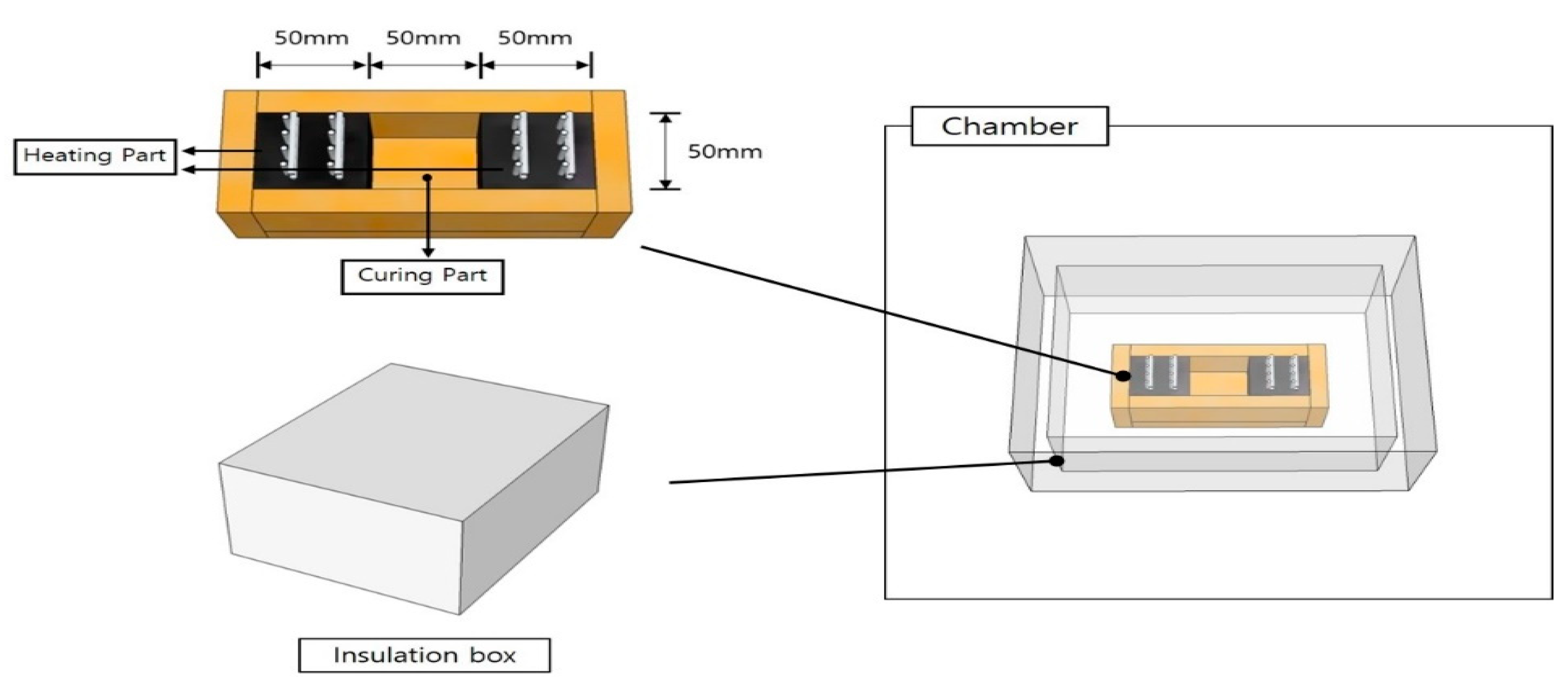
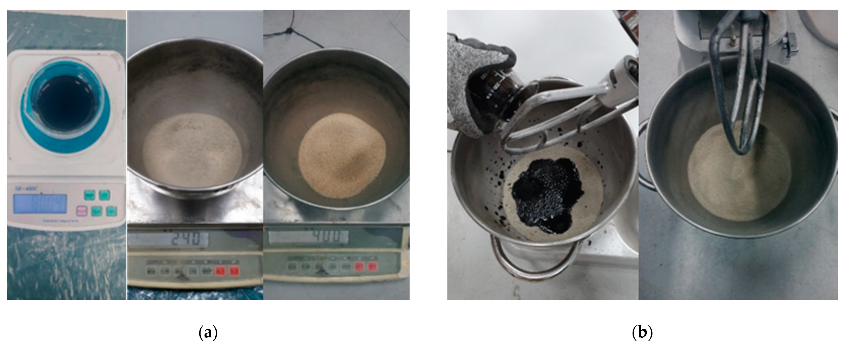
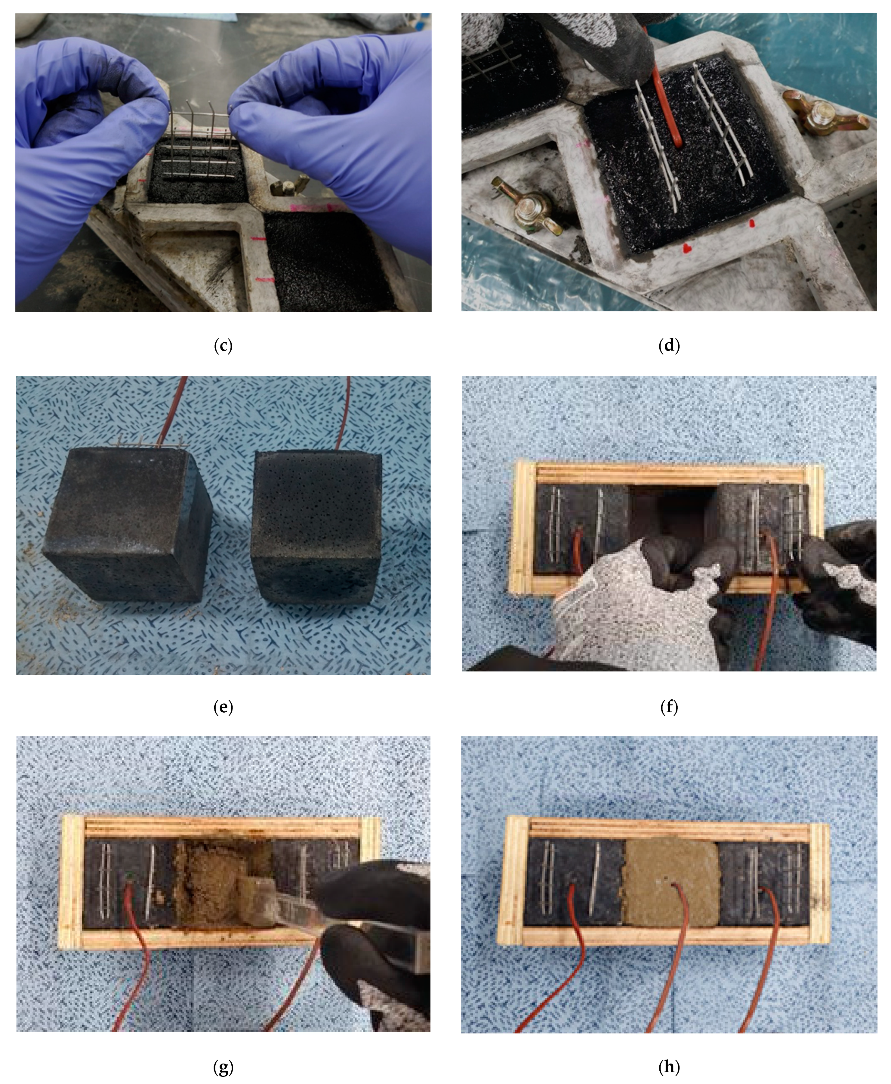
2. Experimental Methods

In this study, heat curing experiments on MWCNT cementitious mortar composites were conducted using the ambient sub-zero temperature and MWCNT content as parameters. A test mold composed of a curing part sandwiched between heating parts was used, as shown in Figure 1. Table 1 lists the parameters for the curing part in the heat curing experiment. The parameters used in this study were those optimized in previous studies [4,19,20]. The ambient temperatures were set to −20 °C, −10 °C, and 0 °C in a temperature-controllable chamber, and the MWCNT content of the curing part was set to 0.1 wt% and 1.0 wt% relative to the cement weight [19,20]. The heat curing experiment was conducted separately for the MWCNT cementitious composites used in their heating and curing parts. For the heating parts, the MWCNT cementitious composite was fabricated by mixing cement with 1.0 wt% MWCNT relative to the cement weight; after which, the composite was dry-cured for 91 d [19,21,22,23]. For the curing part, the MWCNT cementitious composite was mixed with different contents of MWCNTs and poured between the heating parts. To analyze the initial compressive strength of the curing part of the MWCNT cementitious composite according to the ambient temperature and MWCNT content, the compressive strength was tested at 7 and 28 d after the heating experiment (Figure 2). A microstructure analysis of the CNT cementitious composite was conducted using field-emission scanning electron microscopy (FE-SEM) to examine the effects of CNTs on the thermal conductivity [20,24,25,26,27,28,29,30,31].
The specimen notations are based on the application of heat curing, MWCNT mixing, MWCNT content, and ambient temperature. For simplicity, the following annotations are used hereafter. First, “HT” indicates a heat-cured specimen, and “NHT” a specimen that was left at ambient temperature without heat curing. Second, “OPC” indicates ordinary Portland cement (OPC) without MWCNTs, and “MW” a cementitious composite mixed with MWCNTs. Third, numbers 0.0, 0.1, and 1.0 indicate the MWCNT content relative to the cement weight. Finally, numbers 0, 10, and 20 indicate ambient temperatures of 0 °C, −10 °C, and −20 °C, respectively. For example, NHT-OPC-0.0-0 denotes OPC not heat cured but left at an ambient temperature of 0 °C. Similarly, HT-MW-1.0-20 denotes a 1.0 wt% MWCNT cementitious composite heat cured at −20 °C. The MWCNT cementitious composite was fabricated in accordance with the cement mortar compressive strength test standard ASTM C 109 with a size of 50 × 50 × 50 mm3, and 60 specimens were fabricated (five specimens for each parameter set) [32,33]. The curing of the MWCNT cementitious composite was performed by dry-curing to minimize the effect of moisture on both the heating and curing parts.
The specimens were fabricated using grade 1 OPC and typical sand following the ISO 679 standard [33]. The mean diameter of the MWCNTs used in this experiment was 9.5 nm, and the mean length was 1.5 μm. To ensure dispersibility, the MWCNTs were ultrasonically dispersed in a polyacrylic acid copolymer using 22-kHz ultrasonic waves for 2 h [33,34,35,36,37]. Figure 3 shows the fabrication process of the test specimens. The mold was divided into three 50-mm parts; the two parts at both ends were set as heating parts, and the center was set as the curing part. The water/cement ratio applied for the fabrication of the specimens was 0.5, and the mixing ratio of water, cement, and sand was set to 1:2:5. As shown in Figure 3a, the MWCNT solution, cement, and sand were weighed according to the mixing ratio. The cement and sand were dry-mixed for 2 min to ensure material homogeneity; then, the MWCNT solution was added to the cement sand and mixed for 3 min (Figure 3b). After mixing, the MWCNT cementitious composite was poured into the mold in three parts and compacted 30 times each. A stainless-steel mesh was inserted into the cementitious composite of the heating parts, and a voltage was supplied to the mesh. A thermocouple was inserted into both the heating and curing parts, and the internal temperatures were measured [38]. Two stainless steel meshes were inserted at 20-mm intervals in the MWCNT cementitious composite, as shown in Figure 3c. The thermocouple was inserted 24-mm deep at the center of the specimen (Figure 3d). The MWCNT cementitious composite was demolded after 24 h of curing and then dry-cured for 91 d to minimize the effect of moisture (Figure 3e). The MWCNT cementitious composites of the heating parts were installed in the mold, as shown in Figure 3f. The cementitious composite of the curing part was poured between the MWCNT cementitious composites in the heating parts. In addition, the cementitious composite of the curing part was compacted in three layers, as shown in Figure 3g, and the thermocouple was inserted at a depth of 25 mm to measure the internal temperature during the heat curing experiment (Figure 3h).
The heat curing experiment was performed by adjusting the ambient temperature in the chamber. The properties of the chambers used are listed in Table 2. To simulate the actual concrete curing environment, the specimen was covered by an insulation box built in advance. A voltage was supplied for 4 h by connecting a power supply (EX-200) to the electrode installed in the MWCNT cementitious composites of the heating parts. The internal temperatures of the cementitious composites of the heating and curing parts were measured by connecting the thermocouple inserted at the center of the specimen to a static data logger (TDS-303). The specimens were placed inside the chamber, as shown in Figure 4.

3. Experimental Results

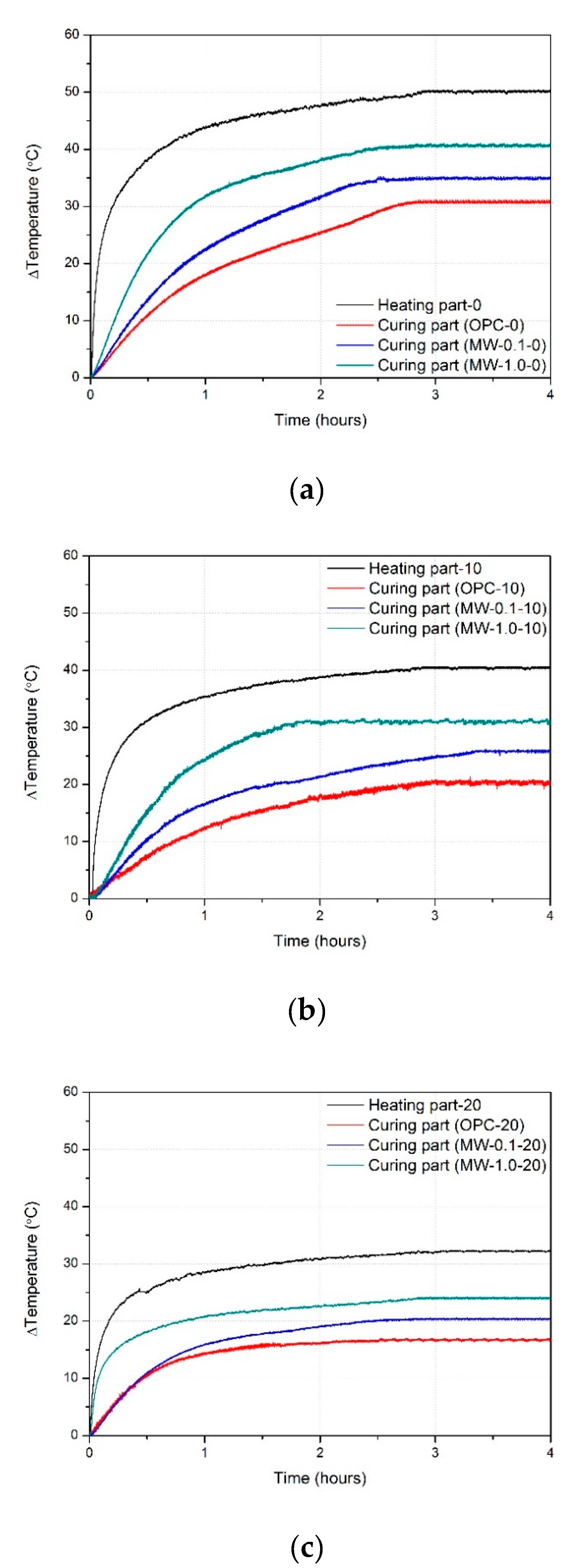
3.1. Results of Heat Curing Experiment

Once the temperature of the chamber was set, it was regulated by the activation of a cooler when the heating part caused the temperature to increase. Owing to this, maintaining a constant temperature for this experiment was difficult. When heat curing is performed in the field, a closed system is created using a cast or heat protection to prevent temperature differences between the inner and outer portions of the cement due to heat loss to the ambient environment. Such temperature differences can cause initial cracking, thus weakening the cement. In this study, to analyze the heat curing of cement composites at sub-zero temperatures, the gap due to the temperature change inside the chamber was eliminated by using an insulation box. Figure 5 shows the temperature changes inside and outside the insulation box during the heat curing experiment. The internal temperature of the insulation box increased gradually with time. When the ambient temperatures were −20 °C, −10 °C, and 0 °C, the temperatures inside the box were −10.2 °C, 1.7 °C, and 14.7 °C, respectively. The MWCNT cementitious composites inside the box increased the internal temperature of the box by generating heat during voltage supply. The temperature inside the insulation box was higher than the ambient temperature by 10 °C or more, and the internal temperature increase improved as the ambient temperature increased.
Figure 6 shows the internal temperature graphs of the heating and curing parts of the MWCNT cementitious composite specimens during heat curing without the insulation box at ambient temperatures of 0 °C, −10 °C, and −20 °C. The internal temperatures of the heating part increased by 53.2 °C, 30.1 °C, and 20.6 °C when curing at ambient temperatures of 0 °C, −10 °C, and −20 °C, respectively. The internal temperatures of the curing part of the OPC, a 0.1 wt% MWCNT cementitious composite, and a 1.0 wt% MWCNT cementitious composite increased as follows: by 29.3 °C, 32.5 °C, and 37.3 °C at an ambient temperature of 0 °C; by 11 °C, 17 °C, and 19.3 °C at an ambient temperature of −10 °C; and by 8.7 °C, 10 °C, and 14.3 °C at an ambient temperature of −20 °C. At the first ambient temperature, the internal temperature increases of the 0.1 wt% and 1.0 wt% MWCNTs were higher than that of OPC by 10.9% and 27.3%, respectively. At -10 °C, the corresponding temperatures increased by 54.5% and 75.5%, respectively, in the curing part. Finally, when the ambient temperature was –20 °C, the internal temperature increases of the 0.1 wt% and 1.0 wt% MWCNTs were higher than that of OPC by 14.9% and 64.4%, respectively, in the curing part. The internal temperature change of the cementitious composite in the curing part was sensitive to the heating temperature of the MWCNT cementitious composite in the heating part and the ambient temperature. When the same voltage was supplied to the MWCNT cementitious composite in the heating part, the internal heating temperature increased with the MWCNT content. As the MWCNT content increased, the heat transferred from the MWCNT cementitious composite in the heating part to that in the curing part increased. Thus, the internal temperature of the cementitious composite in the curing part also increased.
Figure 7 shows the internal temperature graphs of the heating and curing parts of the MWCNT cementitious composite specimens during heat curing with the insulation box at ambient temperatures of 0 °C, −10 °C, and −20 °C. The internal temperature of the heating part increased by 50.2 °C, 40.4 °C, and 32.4 °C when curing at ambient temperatures of 0 °C, −10 °C, and −20 °C, respectively. The internal temperatures of the curing part of the OPC, 0.1 wt% MWCNT cementitious composite, and 1.0 wt% MWCNT cementitious composite increased as follows: by 30.8 °C, 35.0 °C, and 40.8 °C at an ambient temperature of 0 °C; 20.0 °C, 25.8 °C, and 30.7 °C at an ambient temperature of −10 °C; and 16.7 °C, 20.4 °C, and 24.1 °C at an ambient temperature of −20 °C. Compared with the case without the insulation box, the internal temperature changes of the curing part of the OPC, 0.1 wt% MWCNT cementitious composite, and 1.0 wt% MWCNT cementitious composite increased by 5.1%, 7.7%, and 9.4% at an ambient temperature of 0 °C; 81.8%, 51.8%, and 59.1%% at an ambient temperature of −10 °C; and 92.0%, 104.0%, and 68.5%% at an ambient temperature of −20 °C. The installation of the insulation box created an environment similar to a closed system with no heat loss. The temperature change inside the insulation box increased, because the insulation box increased the heating effect of the heat generated in the heating part of the MWCNT cementitious composite (Figure 5). The increased internal temperature of the specimen increased the surface temperature, which, in turn, increased the heating temperature of the heating part of the MWCNT cementitious composite. Consequently, the internal temperature increase of the cementitious composite in the curing part was enhanced.

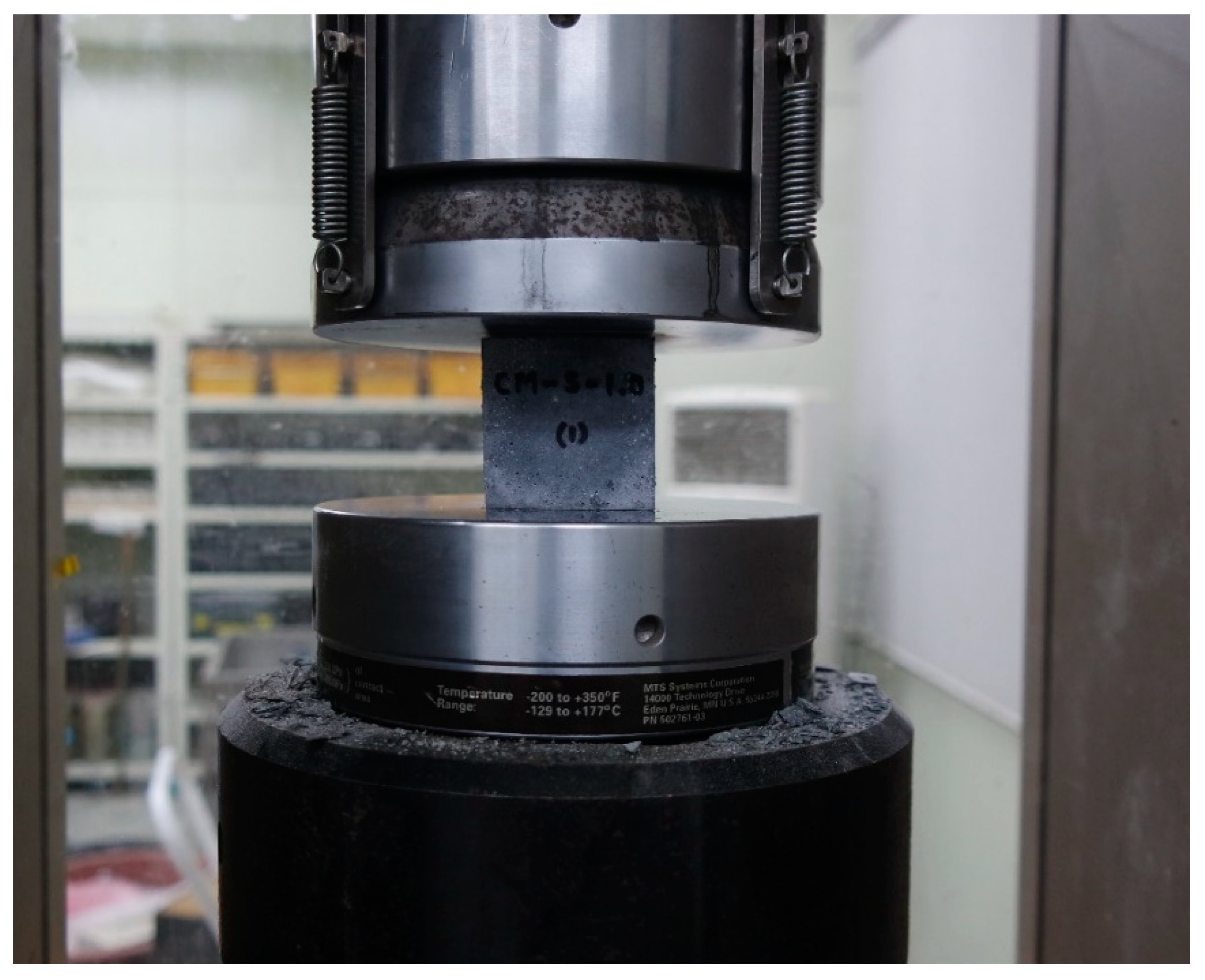
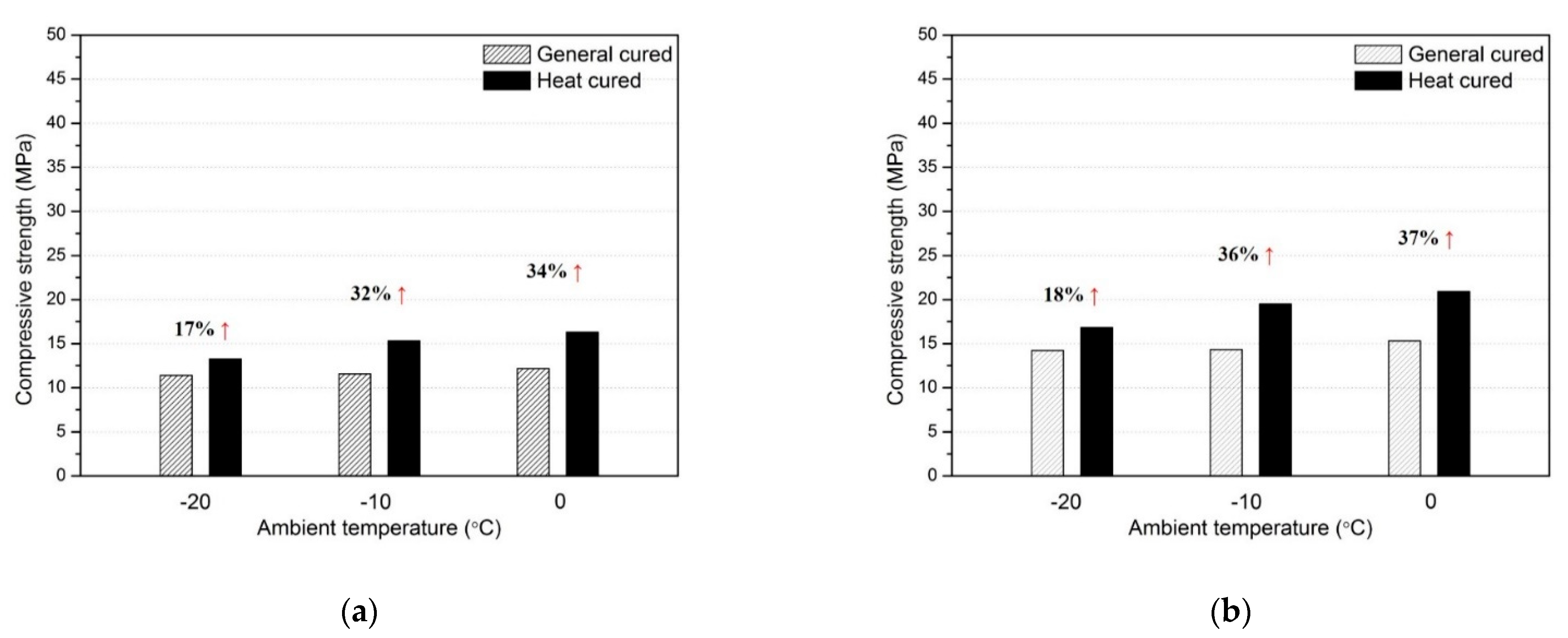
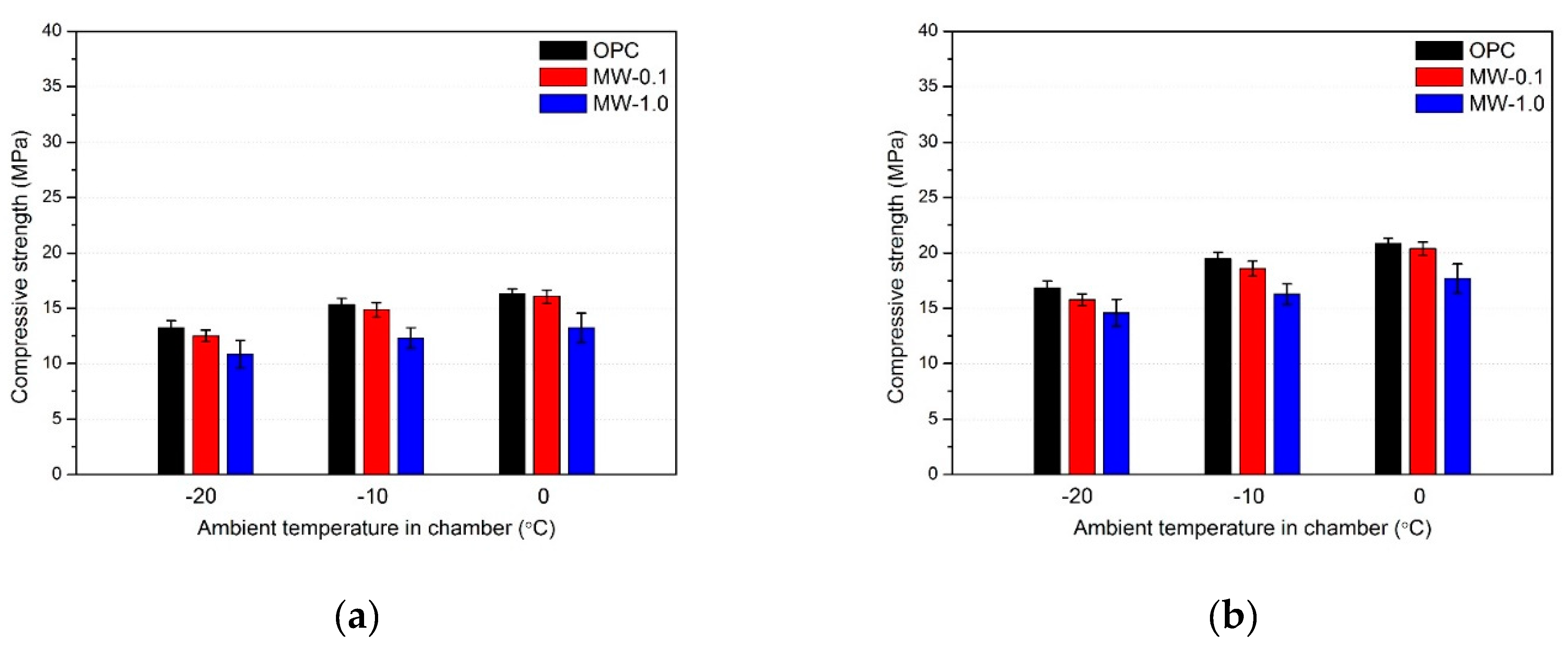
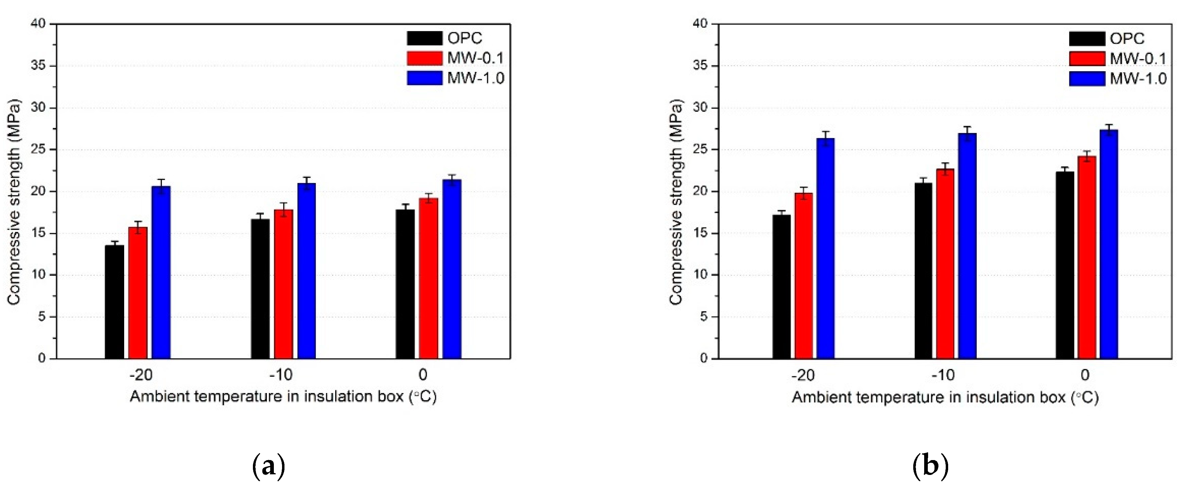
3.2. Results of Compressive Strength Test

Table 3 summarizes the results of the compressive strength test for the curing specimen. The specimen was cured in the chamber for 7 and 28 d. Figure 8 shows a graph of the compressive strength improvement effect of the heat-cured curing part of the OPC. Figure 8a,b shows the results of the compressive strengths of the cement mortar 7 and 28 d after heat curing, respectively. The strengths of the heat-cured specimens were 13.3 MPa, 15.3 MPa, and 16.3 MPa for the 7-d compressive strength test and 16.8 MPa, 19.5 MPa, and 20.9 MPa for the 28-d compressive strength test at ambient temperatures of −10 °C, −20 °C, and 0 °C, respectively. As the ambient temperature increased, the compressive strength also increased. Heat curing resulted in an increase in the compressive strength by 17%, 32%, and 34% for the 7-d test and by 18%, 36%, and 37% for the 28-d test at ambient temperatures of −10 °C, −20 °C, and 0 °C, respectively. The compressive strength improvement effect of heat curing was the lowest at an ambient temperature of −20 °C. The heating temperature of the heating part of the MWCNT cementitious composite increased with the increasing ambient temperature. At sub-zero temperatures, the compressive strength of the heat-cured specimen was higher than that of the specimen that was not heat-cured. Hydration does not occur in a specimen exposed to sub-zero temperatures because of the freezing of internal moisture, which leads to the expansion of the pores inside the specimen. By contrast, the internal temperature of the heat-cured specimen was maintained at 8 °C or higher, and the moisture was not frozen, thus improving the compressive strength.
Figure 9 shows the results of the 7-d and 28-d compressive strength tests for the heat-cured part of the specimens without an insulation box at ambient temperatures of 0 °C, −10 °C, and −20 °C. The initial compressive strengths of the curing part for the 7-d test for the OPC, 0.1 wt% MWCNT cementitious composite, and 1.0 wt% MWCNT cementitious composite were as follows: 16.3 MPa, 16.1 MPa, and 13.2 MPa at an ambient temperature of 0 °C; 15.3 MPa, 14.9 MPa, and 12.3 MPa at an ambient temperature of −10 °C; and 13.3 MPa, 12.5 MPa, and 10.9 MPa at an ambient temperature of −20 °C. For the 28-d test, the initial compressive strengths of the curing part for the OPC and 0.1 wt% and 1.0 wt% MWCNT cementitious composites were as follows: 20.9 MPa, 20.4 MPa, and 17.7 MPa at an ambient temperature of 0 °C and 19.5 MPa, 18.6 MPa, and 16.3 MPa at an ambient temperature of −10 °C. For the 28-d test at an ambient temperature of −20 °C, the initial compressive strengths were 16.8 MPa and 14.6 MPa for the OPC and 1.0 wt% MWCNT cementitious composite, respectively. Consequently, the compressive strength of the specimens cured for 7 d decreased as the MWCNT content increased. Thus, as shown in Figure 9b, when the insulation box was not installed, the compressive strength of the specimens decreased by up to 16.4% as the MWCNT content increased.
Figure 10 shows the results of the compressive strength test for the heat-cured specimen with an insulation box. In contrast to the results shown in Figure 9, when the insulation box was installed, the initial compressive strength of the heat-cured specimens increased with the increasing MWCNT content. Figure 10a shows the results of the 7-d compressive strength test for the heat-cured specimen. When the ambient temperature was −20 °C, the compressive strength of the curing part of the specimen cured for 7 d was 13.5 MPa and 20.6 MPa for the OPC and 1.0 wt% MWCNT cementitious composite, respectively. At an ambient temperature of 0 °C, the compressive strengths were 17.8 MPa, 19.2 MPa, and 21.4 MPa for the OPC and 0.1 wt% and 1.0 wt% MWCNT cementitious composites, respectively. The results of the heat curing test showed that the temperature inside the box increased by 10 °C or more with respect to the ambient temperature, and the center temperature of the MWCNT cementitious composite increased by 10 °C or more, thus improving the heat curing effect. Figure 10b shows the results of the 28-d compressive strength test for the heat-cured specimens. The compressive strengths of the part cured for 28 d for the OPC, 0.1 wt% MWCNT cementitious composite, and 1.0 wt% MWCNT cementitious composite were as follows: 17.2 MPa, 19.8 MPa, and 26.3 MPa at an ambient temperature of −20 °C and 22.3 MPa, 24.2 MPa, and 27.3. MPa at 0 °C. As shown in Figure 10b, the insulation box improved the compressive strength of the specimens by up to 52.9% as the MWCNT content increased. However, the compressive strength of the specimens cured for 7 d decreased with the ambient temperature, regardless of whether the insulation box was installed. The heating temperature of the heating part of the MWCNT cementitious composite decreased with the decreasing ambient temperature; as a result, the heat transferred to the cementitious composite of the curing part decreased. Consequently, the normal compressive strength was not developed, because the internal temperature of the cementitious composite of the curing part decreased with the ambient temperature. The MWCNTs act as connectors between the cement hydrates [39]. However, a high thermal conductivity can facilitate the leakage of heat from the heating part to the outside. Therefore, it was determined that, when the insulation box was not used, the MWCNT cementitious composite interfered with heat curing by leaking heat from the heating part, thus lowering the compressive strength compared to the OPC.

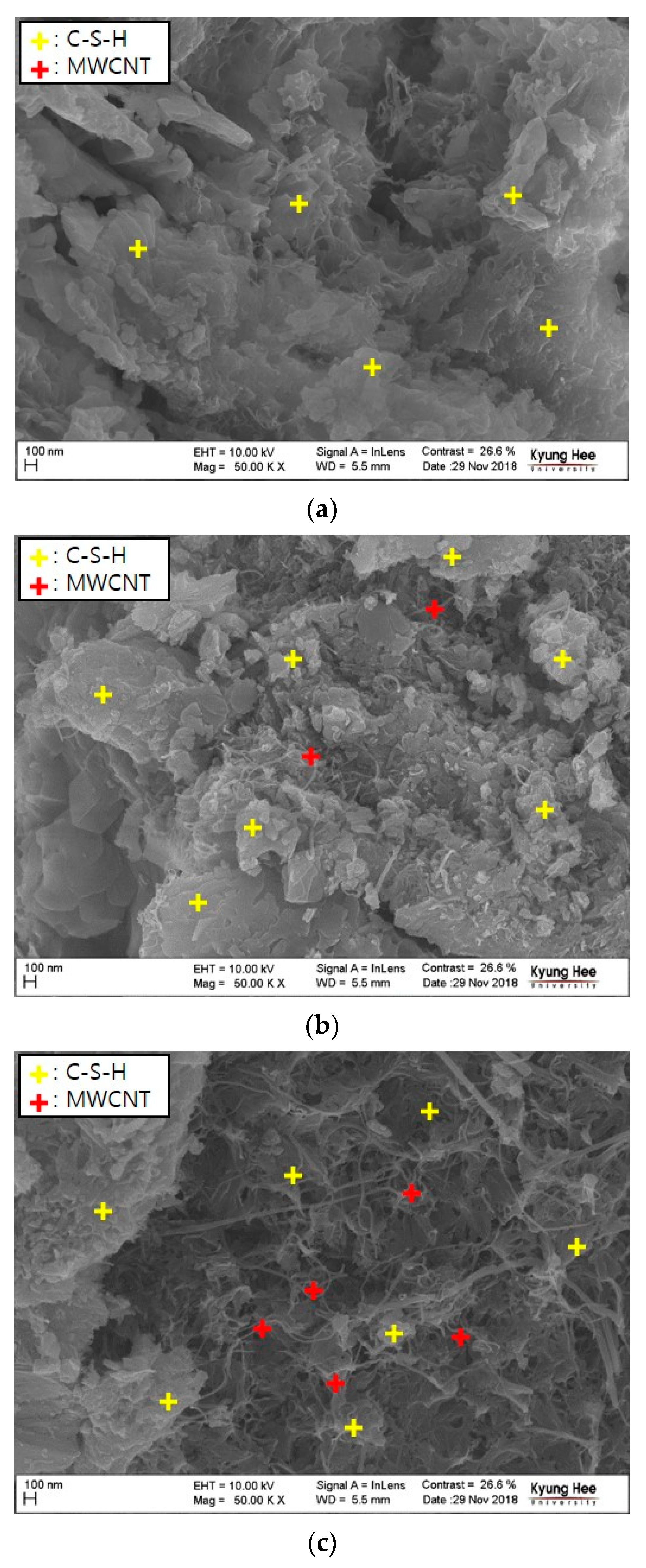
3.3. Results of Microstructure Analysis

Figure 11 shows the results of the FE-SEM analysis of the MWCNT cementitious composites, according to the MWCNT content. The yellow crosses indicate C–S–H (calcium–silicate–hydrate), and the red crosses indicate MWCNTs. Figure 11a shows the internal structure of the OPC without MWCNTs, and many pores were generated among the cement hydrates.
Figure 11b shows the internal structure of the 0.1 wt% MWCNT cementitious composite, which shows a small number of MWCNTs among the cement hydrates. There were fewer pores than OPC, but many pores were generated in the part without MWCNT. The image of the 1.0 wt% MWCNT cementitious composite, which was mixed with a large amount of MWCNTs, showed many MWCNTs distributed throughout the internal structure (Figure 11c). In the 1.0 wt% MWCNT cementitious composite, the evenly distributed MWCNTs acted as bridges for the interconnecting cement hydrates, thus increasing the heat and load transfer efficiency. The mixing of MWCNTs provided additional nucleation sites, thus promoting the generation of a larger amount of C–S–H compared to OPC [40,41,42]. C–S–H, which has a dense structure and high strength, improved the compressive strength of the MWCNT cementitious composite by filling the micropores inside the cementitious composite [43,44].

4. Conclusions

In this study, heat curing experiments were performed on MWCNT cementitious mortar composites under varying ambient temperatures and MWCNT contents. The strength improvement effect of the cured cementitious mortar composite under low ambient temperatures was verified through a compressive strength test. In addition, the effects of the MWCNT content on the heat and strength characteristics were analyzed using FE-SEM. From the results, the following conclusions are drawn.
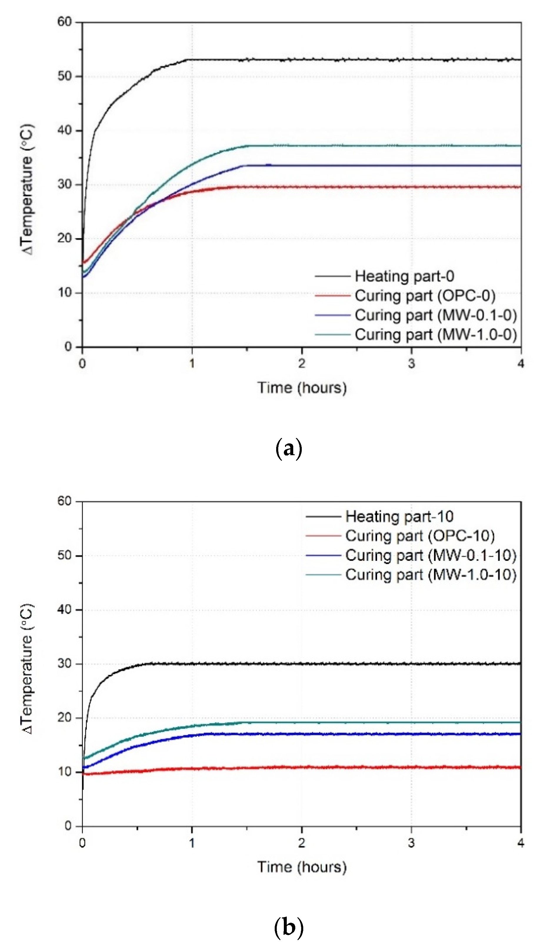
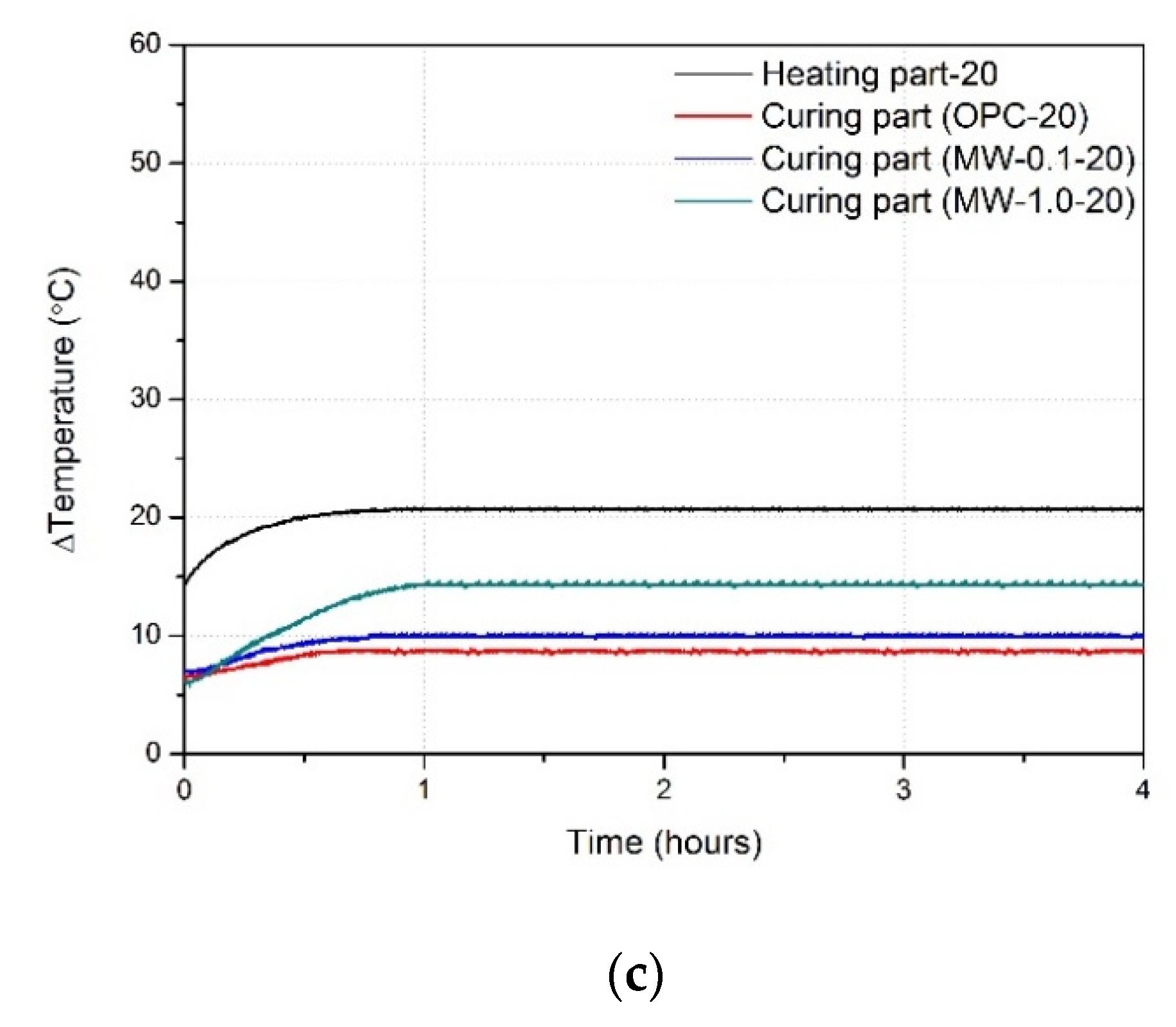
  • The internal temperature change of the MWCNT cementitious mortar composites increased with the increasing ambient temperature and MWCNT content. At higher ambient temperatures, the heating temperature of the heating part of the MWCNT cementitious mortar composite increased, transmitting a large amount of heat to the curing part. Furthermore, owing to the excellent thermal conductivity of MWCNTs, the heat generated in the heating part spread more rapidly to the curing part of the MWCNT cementitious composite compared with the OPC. As the MWCNT content increased, the amount of MWCNTs dispersed inside the cementitious mortar composite increased, and the thermal conductivity of the composite improved.
  • The installation of an insulation box increased the maximum temperature change of the curing part of the MWCNT cementitious mortar composite. The insulation box created an environment similar to a closed system, in which heat generated in the heating part circulated, causing the internal temperature to increase. The temperature on the surface of the cementitious mortar composite also increased, which further increased the heating temperature of the heating part of the MWCNT cementitious mortar composite. Consequently, the maximum temperature change in the cementitious composite of the curing part increased.
  • The results of the compressive strength test under sub-zero temperatures showed that the heat-cured cementitious mortar composite of the curing part with an insulation box had a higher compressive strength than the OPC in the curing part. As the ambient temperature increased, the compressive strength of the cementitious mortar composite of the curing part improved by up to 47%. Inside the insulation box, the internal temperature of the cementitious composite of the heat-cured curing part was maintained at 8 °C or higher, thus preventing the freezing of moisture. Consequently, as the ambient temperature increased, the heating temperature of the MWCNT cementitious mortar composite of the heating part increased, which improved the compressive strength of the cementitious mortar composite of the curing part.
  • When the insulation box was not installed in the heat curing experiment, the compressive strength of the cementitious composite of the curing part decreased with the increasing MWCNT content. In contrast, when the insulation box was installed in the heat curing experiment, the compressive strength of the cementitious composite of the curing part increased by up to 52.9% with the increasing MWCNT content. The MWCNTs not only increased the load transfer efficiency by interconnecting the cement hydrates but also improved the compressive strength of the MWCNT cementitious mortar composites by filling the micropores. The installation of the insulation box created a closed system, and the increased temperature inside the box improved the strength of the MWCNTs. Therefore, it is essential to use an insulation box when using MWCNT cementitious mortar composites for heat curing.
  • The FE-SEM images of the internal microstructure of the MWCNT cementitious mortar composites confirmed the network connections between the MWCNTs and cement hydrates inside the cementitious composites. The thermal conductivity of the cementitious composites improved, because the high thermal conductivity of the MWCNTs interconnected the cement hydrates. Furthermore, the MWCNTs improved the compressive strength by promoting the formation of C–S–H and filling the micropores inside the cementitious mortar composites.

Author Contributions

H.L.: data curation, writing—reviewing and editing, and conceptualization. J.S.: formal analysis and investigation. W.C.: writing—original draft preparation, writing—reviewing and editing, and project administration. All authors have read and agreed to the published version of the manuscript.

Funding

This work was supported by a grant from the Korea Agency for Infrastructure Technology Advancement (KAIA) funded by the Ministry of Land, Infrastructure and Transport (Grant 20CTAP-C157602-01).

Institutional Review Board Statement

Not applicable.

Informed Consent Statement

Not applicable.

Data Availability Statement

Data is contained within the article.

Conflicts of Interest

The authors declare no conflict of interest.

References

  1. Zhang, Q.; Li, H. Experimental investigation on the ice/snow melting performance of CNFP & MWCNT/cement-based deicing system. In Proceedings of the 6th International Workshop on Advanced Smart Materials and Smart Structures Technology, Dalian, China, 25–26 July 2011; pp. 25–26. [Google Scholar]
  2. Won, J.P.; Kim, C.K.; Lee, S.J.; Lee, J.H.; Kim, R.W. Thermal characteristics of a conductive cement-based composite for a snow-melting heated pavement system. Compos. Struct. 2014, 118, 106–111. [Google Scholar] [CrossRef]
  3. Kim, G.M.; Naeem, F.; Kim, H.K.; Lee, H.K. Heating and heat-dependent mechanical characteristics of CNT-embedded cementitious composites. Compos. Struct. 2016, 136, 162–170. [Google Scholar] [CrossRef]
  4. Lee, H.; Song, Y.M.; Loh, K.J.; Chung, W. Thermal response characterization and comparison of carbon nanotube-enhanced cementitious composites. Compos. Struct. 2018, 202, 1042–1050. [Google Scholar] [CrossRef] [Green Version]
  5. Al-Khaiat, H.; Haque, M.N. Effect of initial curing on early strength and physical properties of a lightweight concrete. Cem. Concr. Res. 1998, 28, 859–866. [Google Scholar] [CrossRef]
  6. Sukumar, B.; Nagamani, K.; Raghavan, R.S. Evaluation of strength at early ages of self-compacting concrete with high volume fly ash. Constr. Build. Mater. 2008, 122, 394–1401. [Google Scholar] [CrossRef]
  7. Assi, L.N.; Deaver, E.E.; ElBatanouny, M.K.; Ziehl, P. Investigation of early compressive strength of fly ash-based geopolymer concrete. Constr. Build. Mater. 2016, 112, 807–815. [Google Scholar] [CrossRef] [Green Version]
  8. Li, G.; Zhao, X. Properties of concrete incorporating fly ash and ground granulated blast-furnace slag. Cem. Concr. Compos. 2003, 25, 293–299. [Google Scholar] [CrossRef]
  9. Kim, J.K.; Moon, Y.H.; Eo, S.H. Compressive strength development of concrete with different curing time and temperature. Cem. Concr. Res. 1998, 28, 1761–1773. [Google Scholar] [CrossRef]
  10. Lura, P.; van Breugel, K.; Maruyama, I. Effect of curing temperature and type of cement on early-age shrinkage of high-performance concrete. Cem. Concr. Res. 2001, 31, 1867–1872. [Google Scholar] [CrossRef]
  11. Arioz, O. Effects of elevated temperatures on properties of concrete. Fire Saf. J. 2007, 42, 516–522. [Google Scholar] [CrossRef]
  12. Husem, M.; Gozutok, S. The effects of low temperature curing on the compressive strength of ordinary and high performance concrete. Constr. Build. Mater. 2005, 19, 49–53. [Google Scholar] [CrossRef]
  13. Chaipanich, A.; Nochaiya, T.; Wongkeo, W.; Torkittikul, P. Compressive strength and microstructure of carbon nanotubes–fly ash cement composites. Mater. Sci. Eng. A 2010, 527, 1063–1067. [Google Scholar] [CrossRef]
  14. Manzur, T.; Yazdani, N.; Emon, M.; Bashar, A. Effect of carbon nanotube size on compressive strengths of nanotube reinforced cementitious composites. J. Mater. 2014, 2014, 1–8. [Google Scholar] [CrossRef]
  15. Li, G.Y.; Wang, P.M.; Zhao, X. Mechanical behavior and microstructure of cement composites incorporating surface-treated multi-walled carbon nanotubes. Carbon 2005, 436, 1239–1245. [Google Scholar] [CrossRef]
  16. Al-Rub, R.K.A.; Ashour, A.I.; Tyson, B.M. On the aspect ratio effect of multi-walled carbon nanotube reinforcements on the mechanical properties of cementitious nanocomposites. Constr. Build. Mater. 2012, 35, 647–655. [Google Scholar] [CrossRef]
  17. Mohsen, M.O.; Al-Nuaimi, N.; Al-Rub, R.K.A.; Senouci, A.; Bani-Hani, K.A. Effect of mixing duration on flexural strength of multi walled carbon nanotubes cementitious composites. Constr. Build. Mater. 2016, 126, 586–598. [Google Scholar] [CrossRef]
  18. Tyson, B.M.; Abu Al-Rub, R.K.; Yazdanbakhsh, A.; Grasley, Z. Carbon nanotubes and carbon nanofibers for enhancing the mechanical properties of nanocomposite cementitious materials. J. Mater. Civ. Eng. 2011, 23, 1028–1035. [Google Scholar] [CrossRef]
  19. Lee, H.; Park, S.; Cho, S.; Chung, W. Correlation analysis of heating performance and electrical energy of multi-walled carbon nanotubes cementitious composites at sub-zero temperatures. Compos. Struct. 2020, 238, 111977. [Google Scholar] [CrossRef]
  20. Lee, H.; Park, S.; Park, S.; Chung, W. Enhanced Detection Systems of Filling Rates Using Carbon Nanotube Cement Grout. Nanomaterials 2020, 10, 10. [Google Scholar] [CrossRef] [PubMed] [Green Version]
  21. Gomis, J.; Galao, O.; Gomis, V.; Zornoza, E.; Garcés, P. Self-heating and deicing conductive cement: Experimental study and modeling. Constr. Build. Mater. 2015, 75, 442–449. [Google Scholar] [CrossRef]
  22. Tawfik, T.A.; Abd El-Aziz, M.A.; Abd El-Aleem, S.; Serag Faried, A. Influence of nanoparticles on mechanical and nondestructive properties of high-performance concrete. J. Chin. Adv. Mater. Soc. 2018, 6, 409–433. [Google Scholar] [CrossRef]
  23. Cha, S.W.; Song, C.; Cho, Y.H.; Choi, S. Piezoresistive properties of CNT reinforced cementitious composites. Mater. Res. Innov. 2014, 18 (Suppl. 2), S2-716. [Google Scholar] [CrossRef]
  24. Liew, K.M.; Kai, M.F.; Zhang, L.W. Mechanical and damping properties of CNT-reinforced cementitious composites. Compos. Struct. 2017, 160, 81–88. [Google Scholar] [CrossRef]
  25. Han, B.; Zhang, K.; Yu, X.; Kwon, E.; Ou, J. Fabrication of piezoresistive CNT/CNF cementitious composites with superplasticizer as dispersant. J. Mater. Civ. Eng. 2011, 24, 658–665. [Google Scholar] [CrossRef]
  26. Lee, H.; Kang, D.; Song, Y.M.; Chung, W. Heating experiment of CNT cementitious composites with single-walled and multiwalled carbon nanotubes. J. Nanomater. 2017, 2017, 1–8. [Google Scholar] [CrossRef] [Green Version]
  27. Wang, B.; Han, Y.; Zhang, T. Morphological properties of surface-treated carbon nanotubes in cement-based composites. J. Nanosci. Nanotechnol. 2012, 12, 8415–8419. [Google Scholar] [CrossRef]
  28. Lu, L.; Ouyang, D.; Xu, W. Mechanical properties and durability of ultra high strength concrete incorporating multi-walled carbon nanotubes. Materials 2016, 9, 419. [Google Scholar] [CrossRef] [PubMed] [Green Version]
  29. Siddique, R.; Mehta, A. Effect of carbon nanotubes on properties of cement mortars. Constr. Build. Mater. 2014, 50, 116–129. [Google Scholar] [CrossRef]
  30. Carriço, A.; Bogas, J.A.; Hawreen, A.; Guedes, M. Durability of multi-walled carbon nanotube reinforced concrete. Constr. Build. Mater. 2018, 164, 121–133. [Google Scholar] [CrossRef]
  31. Lee, H.; Yu, W.; Loh, K.J.; Chung, W. Self-heating and electrical performance of carbon nanotube-enhanced cement composites. Constr. Build. Mater. 2020, 250, 118838. [Google Scholar] [CrossRef]
  32. ASTM C 109. Standard Test Method for Compressive Strength of Hydraulic Cement Mortars (Using 2-in, or [50-mm] Cube Specimens); ASTM International: West Conshohocken, PA, USA, 2016. [Google Scholar]
  33. ISO (International Organisation for Standardisation). ISO 679. Cement–Test Methods–Determination of Strength; ISO: Geneva, Switzerland, 2009. [Google Scholar]
  34. Lee, H.; Jeong, S.; Park, S.; Chung, W. Enhanced mechanical and heating performance of multi-walled carbon nanotube-cement composites fabricated using different mixing methods. Compos. Struct. 2019, 225, 111072. [Google Scholar] [CrossRef]
  35. Wang, B.; Han, Y.; Liu, S. Effect of highly dispersed carbon nanotubes on the flexural toughness of cement-based composites. Constr. Build. Mater. 2013, 46, 8–12. [Google Scholar] [CrossRef]
  36. Kim, G.M.; Yang, B.J.; Cho, K.J.; Kim, E.M.; Lee, H.K. Influences of CNT dispersion and pore characteristics on the electrical performance of cementitious composites. Compos. Struct. 2017, 164, 32–42. [Google Scholar] [CrossRef]
  37. Hu, Y.; Luo, D.; Li, P.; Li, Q.; Sun, G. Fracture toughness enhancement of cement paste with multi-walled carbon nanotubes. Constr. Build. Mater. 2014, 70, 332–338. [Google Scholar] [CrossRef]
  38. Lee, H.; Kang, D.; Kim, J.; Choi, W.C. Void detection of cementitious grout composite using single-walled and multi-walled carbon nanotubes. Cem. Concr. Compos. 2019, 95, 237–246. [Google Scholar] [CrossRef]
  39. Lee, H.; Jeong, S.; Cho, S.; Chung, W. Enhanced bonding behavior of multi-walled carbon nanotube cement composites and reinforcing bars. Compos. Struct. 2020, 112201. [Google Scholar] [CrossRef]
  40. Naqi, A.; Abbas, N.; Zahra, N.; Hussain, A.; Shabbir, S.Q. Effect of multi-walled carbon nanotubes (MWCNTs) on the strength development of cementitious materials. J. Mater. Res. Technol. 2019, 8, 1203–1211. [Google Scholar] [CrossRef]
  41. Thomas, J.J.; Jennings, H.M.; Chen, J.J. Influence of nucleation seeding on the hydration mechanisms of tricalcium silicate and cement. J. Phys. Chem. C 2009, 113, 4327–4334. [Google Scholar] [CrossRef] [Green Version]
  42. Morsy, M.S.; Alsayed, S.H.; Aqel, M. Hybrid effect of carbon nanotube and nano-clay on physico-mechanical properties of cement mortar. Constr. Build. Mater. 2011, 25, 145–149. [Google Scholar] [CrossRef]
  43. Bharj, J.; Singh, S.; Chander, S.; Singh, R. Role of dispersion of multiwalled carbon Nanotubes on compressive strength of cement paste. World Academy of Science, Engineering and Technology. Int. J. Math. Comput. Phys. Electr. Comput. Eng. 2014, 8, 340–343. [Google Scholar]
  44. Nochaiya, T.; Chaipanich, A. Behavior of multi-walled carbon nanotubes on the porosity and microstructure of cement-based materials. Appl. Surf. Sci. 2011, 257, 1941–1945. [Google Scholar] [CrossRef]
Figure 1. Test mold of the cementitious composites specimens.
Crystals 11 01182 g001
Figure 2. Setup of the compressive strength test of the specimens.
Crystals 11 01182 g002
Figure 3. Fabrication process of the test specimens. (a) Measuring. (b) Mixing (3 min). (c) Installing a stainless-steel mesh. (d) Installing a thermocouple in the heating part. (e) Curing of the heating part (91 d). (f) Installing the heating part. (g) Tamping of the curing part. (h) Installing a thermocouple in the curing part.
Crystals 11 01182 g003aCrystals 11 01182 g003b
Figure 4. Setup of the heat curing experiment.
Crystals 11 01182 g004
Figure 5. Temperature versus time at a chamber temperature of (a) 0 °C, (b) 10 °C, and (c) 20 °C inside and outside the insulation box.
Crystals 11 01182 g005
Figure 6. Temperature variation of the specimens with heat curing versus time at a chamber temperature of (a) 0 °C, (b) 10 °C, and (c) 20 °C.
Crystals 11 01182 g006aCrystals 11 01182 g006b
Figure 7. Temperature variation of the specimens with heat curing in the insulation box at a chamber temperature of (a) 0 °C, (b) 10 °C, and (c) 20 °C.
Crystals 11 01182 g007
Figure 8. Compressive strength of the OPC specimens after (a) 7 days and (b) 28 days.
Crystals 11 01182 g008
Figure 9. Compressive strength of the specimens without the insulation box after (a) 7 days and (b) 28 days.
Crystals 11 01182 g009
Figure 10. Compressive strength of the specimens with the insulation box after (a) 7 days and (b) 28 days.
Crystals 11 01182 g010
Figure 11. FE-SEM images of the (a) OPC, (b) MW-0.1, and (c) MW-1.0 specimens.
Crystals 11 01182 g011
Table 1. Test parameters.
Specimen NameMWCNT Content of the Curing Part(wt%)Ambient Temperature(°C)
NHT-OPC-0.0-00.00
HT-OPC-0.0-00.0
HT-MW-0.1-00.1
HT-MW-1.0-01.0
NHT-OPC-0.0-100.1−10
HT-OPC-0.0-101.0
HT-MW-0.1-100.0
HT-MW-1.0-100.1
NHT-OPC-0.0-201.0−20
HT-OPC-0.0-200.0
HT-MW-0.1-200.1
HT-MW-1.0-201.0
Table 2. Chamber specifications.
PropertyUnitValue
Maximum temperature°C−20
Minimum temperature°C100
Humidity range%30–90
Capacity/volume m 3 0.28
Power requirementsV200–208
Table 3. Compressive strength of the specimens.
Specimen NameCompressive Strength (MPa)
UninsulatedInsulated
7 d28 d7 d28 d
HT-OPC-0.0-016.3120.8717.8322.30
HT-MW-0.1-016.0520.3819.2124.2
HT-MW-1.0-013.2417.6821.3627.35
HT-OPC-0.0-1015.3219.4616.6620.99
HT-MW-0.1-1014.8618.5717.8422.65
HT-MW-1.0-1012.3216.2820.9726.91
HT-OPC-0.0-2013.2516.8313.5217.17
HT-MW-0.1-2012.5115.7615.7219.81
HT-MW-1.0-2010.8614.5720.5826.34
Publisher’s Note: MDPI stays neutral with regard to jurisdictional claims in published maps and institutional affiliations.

