1. Introduction
Light control is extremely important for observing objects correctly without stress. In particular, the light observed directly from the sky to the eyes can be a large hindrance to observing an object correctly. Under typical conditions, objects are observed in the front or lower direction. Therefore, optical filters whose transmittance is small in the upward direction and large in the front or downward directions should be valuable.
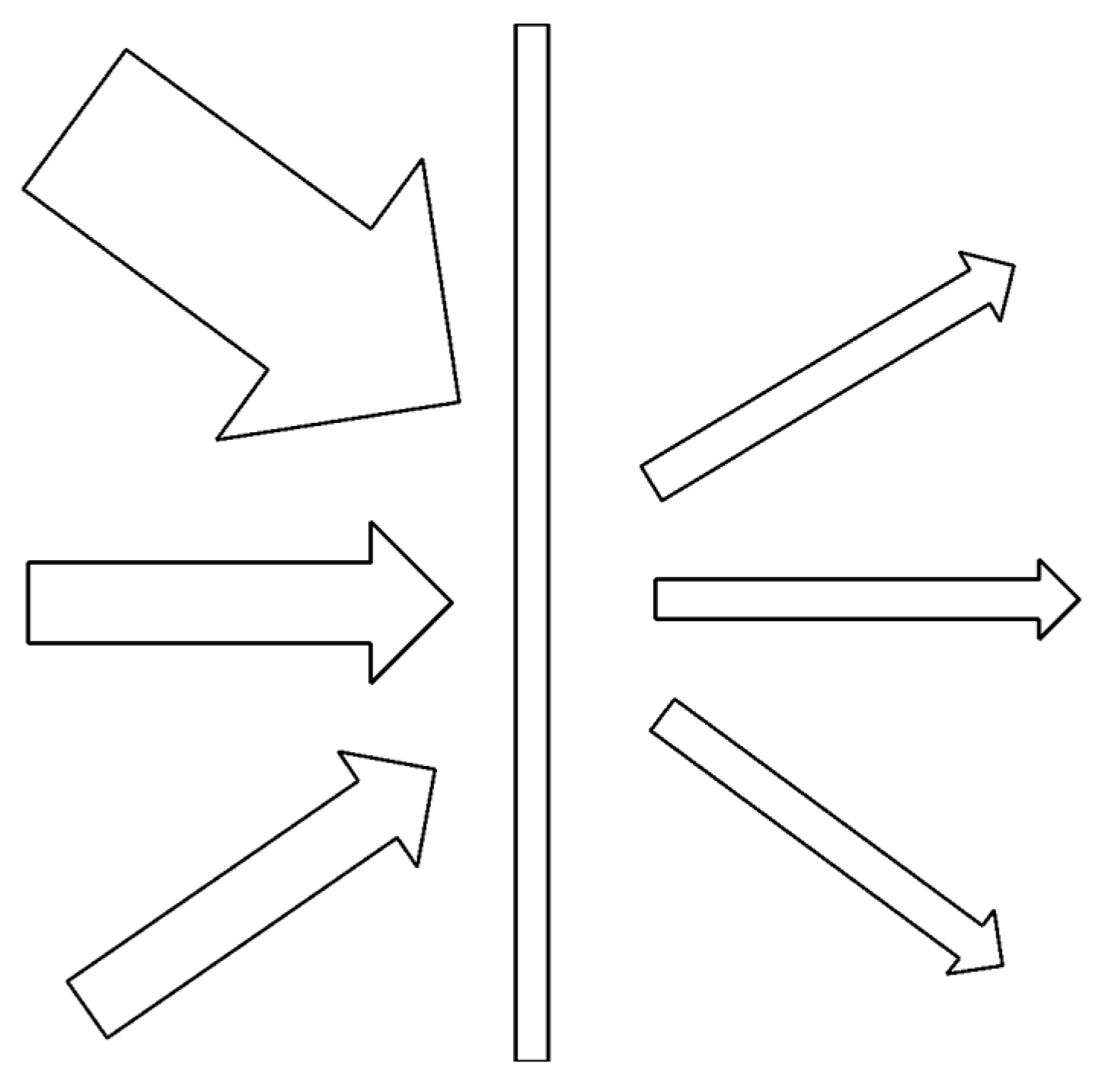
Figure 1 shows the function of the optical filter with the incident angular dependence of the transmittance, which presents as a “louver” function. The louver can reduce the light only from the upward direction. Thin optical films with this function have a variety of applications, such as buildings, vehicles, and glasses. It can also be valuable if the transmittance is controlled by the electric field. This investigation used guest-host (GH) liquid crystal (LC) devices for these applications. GH-liquid crystal devices (LCDs) are devices that use dichroic dyes without polarizers. The dye molecules are aligned parallel to the molecular axis of the LC and absorb polarized light vibrating parallel to the molecular axis.
By using the structure in which the dye molecules decline to the substrate plane, the incident light propagating along the dye molecules passes through the molecules with little absorption, and the light moving perpendicular to the molecular axis is absorbed more effectively. Two types of LCDs possess this structure. The first is the hybrid aligned nematic (HAN) and the other is the high pretilt angle LCDs. High pretilt angle LCDs are defined by alignment layers showing a high pretilt angle, and the directions of LC molecular declination on both substrates are opposite. The structures of these types of LCDs are shown in
Figure 2a,b.
As shown in
Figure 2a, the two substrates of HAN GH-LCDs possess two types of alignment layers, namely a homogeneous and a homeotropic layer. The polar angle of LC molecules varies from 2 or 3 degrees (the pretilt angle of the homogeneous alignment layer) to 90° continuously from the surface of the homogeneous alignment layer to that of the homeotropic alignment layer. Therefore, the molecules at the center of the LC layer are inclined at approximately 45° from the substrate surface plane.
It was proposed that by using an inclined molecular arrangement, the incident angle dependence of the transmittance can be controlled. The reverse polymer-dispersed LC (PD-LC) mode with a HAN structure, which causes light scattering when an electric field is applied, shows the incident angle dependence of the transmittance [
1,
2,
3]. This application has been proposed for smart windows as well as displays and other applications [
4,
5,
6,
7]. In these papers, except for the usage of the light scattering phenomenon [
1,
2,
3], polarized light was used. This is because HAN-LCDs work only for the polarized light vibrating parallel to the LC direction. This study proposes a method for HAN-LCDs to work for non-polarized light.
Figure 2b shows the alignment layers of high pretilt angles. Alignment layers with a high pretilt angle can be realized by a mixture of the polyimide material for homogeneous alignment layers and one for homeotropic alignment layers [
8].
In
Figure 3, the light passes through the single HAN-LCD from the incident angles
Θ and–
θ, where
Θ is the polar angle in the middle of the LCD. The p-wave of the incident light, from the direction
Θ, vibrates parallel to the long axis of the dichroic dye and is absorbed effectively.
In contrast, the vibration of the s-wave is perpendicular to the molecular axis and the absorption is small. For the incident light from the direction of −θ, both the p- and s-waves vibrate perpendicularly to the molecular axis of the dye, resulting in the absorption being small. The transmittance, even from the Θ direction, is not sufficiently reduced owing to the presence of the s-wave.
The optical device shown in
Figure 4 was proposed to realize a large ratio of the light strength from the
Θ and −
θ directions. By utilizing this device, it is possible to realize the ratio between the largest light strength from the −
θ direction and the smallest one from the
Θ direction.
Figure 5 shows the mechanism which causes the incident angle dependence of the transmittance. In the case of incident light to LCD1 from the
Θ direction, the absorption of the p-wave is large, and the one of s-wave is small. By passing through the half-wave plate, the s-wave changes into a p-wave, which is effectively absorbed by passing through LCD2. However, in the case of incident light from the −
θ direction, both p- and s-waves vibrate perpendicular to the dye molecular axis, passing through both LCD1 and LCD2 without large absorption. Therefore, the transmittance from the
Θ direction becomes low and that from the
θ direction becomes high. The device shown in
Figure 4 would realize the largest ratio between the large light strength from the
Θ direction and the smallest one from the −
θ direction.
The demands for the devices which control transmittance depending on the incident angle exist in various situations. Especially, the demand to reduce only sunlight is usual. The function of the devices described in this paper should be desired for sunglasses, sunvisors, vehicle windows, and so on. Furthermore, the demand to show information to the limited direction also exists in the fields of information displays in vehicles, displays for games, and so on. The switching function is also effective for these purposes. The films named “louver film” also have a similar function. However, those films cannot show the switching function, and the incident angle for high transmittance is limited.
3. Results and Discussions
Transmittance Dependences on the Incident Angles for HAN-LCDs
Figure 6 shows the transmittance dependence on the incident angles for HAN-LCDs using LC materials containing 1, 3, and 5 wt.% of the dichroic dye NKX-4173 (Hayashibara Ltd., Japan). In the case of 1 wt.%, the maximum value, minimum value, and ratio between them was 71%, 55%, and 1.3 respectively, in the range of ±45°.
Figure 7 shows the dependence of the transmittance on the incident angles for the 2-layer HAN-LCDs, as shown in
Figure 4, using LC materials containing 1, 3, and 5 wt.% of the dichroic dye NKX-4173 (Hayashibara Ltd., Japan). In the case of 1 wt.%, the maximum value, minimum value, and ratio was 37%, 21%, and 1.8, respectively, in the range of ±45°.
Figure 8 shows the behaviors of the p- and s-waves parallel and perpendicular to the dye molecules for single and two-layer HAN-LCDs. In the case of HAN-LCDs, the polar angle of the LC molecules or dye molecules is distributed from several degrees in the vicinity of one alignment layer to 90° in another. The polar angle of the LC molecule can be considered to represent either the angle in the middle of the LC layer or the average of the LC alignment.
T∥ shows the transmittance of the polarized light vibrating parallel to the molecular axis of the dichroic dye through GH-LC materials. T⊥ shows the transmittance of the polarized light vibrating perpendicular to the molecular axis of the dye.
T∥ and
T⊥ are the transmittances of the p- and s-waves from the angle
Θ in
Figure 8a, respectively.
T⊥ is almost equal to the transmittance p-wave and s-wave from the angle −
θ.
TΘ and
T−θ are the transmittance of light from the incident angles
Θ and −
θ, respectively. As shown in
Figure 8a, for a single cell
T−θ is equal to
T⊥. In the case of light from the incident angle
Θ, the transmittance of the p-wave is equal to
T∥ and that of the s-wave is equal to
T⊥. Generally, the strengths of the p- and s-waves are identical. Consequently,
TΘ can be represented by Equation (1):
and the ratio
r, where
T∥<
T⊥, can be expressed as follows:
Therefore, the ratio r should be limited.
Figure 8b shows the behavior of the p- and s-waves that enter into the two-layer HAN-LCDs from the incident angle −
θ and
Θ. The transmittance of the p-wave through LCD1 from the incident angle −
θ can be considered to be
T⊥, as described above. The p-wave changes into the s-wave by passing through the half-wave plate. The transmittance of the s-wave is also considered to be equal to
T⊥. Therefore, the transmittance of the p-wave passing through two-layer LCDs is
T⊥2. The transmittance of the s-wave incident from −
θ passing through two-layer HAN-LCDs is also equal to
T⊥2. As a result, the transmittance of the incident light from −
θ should be
T⊥2.
The transmittance of the p-wave through LCD1 from the incident angle
Θ can be expressed as
T∥. The p-wave changes to the s-wave by a half-wave plate. As a result, the p-wave transmittance from the incident angle
Θ can be represented by Equation (3):
In contrast, the s-wave transmittance for LCD1 is T⊥ and changes to a p-wave by a half-wave plate. The p-wave transmittance through LCD2 is represented by Equation (3). Consequently, the transmittance of the incident light from Θ can be expressed by Equation (3).
The ratio
r of the maximum transmittance
T−θ and minimum transmittance
TΘ can be expressed as follows:
For an increasing T⊥ and T∥ ratio, it is effective to increase the dichroic ratio of the dye and the order parameters of the LC materials. Increasing the dye concentration and the cell thickness is effective in increasing the r value by reducing the minimum transmittance, TΘ. The required maximum transmittance is determined depending on the application. Therefore, to achieve a large r value, the dichroic ratio of the dye and the order parameters of the LC materials are important.
Figure 9 shows the dependence of the transmittance on the incident angles for HAN-LCDs using LC materials containing 1, 3, and 5 wt.% of the dichroic dye NKX-4173 (Hayashibara Ltd., Japan) with a polarizer. The optical axis of the polarizer was parallel to the alignment direction of the HAN-LCD. The transmittance was halved with the use of the polarizer. From
Figure 9, it can be determined that
T∥ was 0.32, and
T⊥ was 0.62 for 1 wt.%. For these values, the transmittance in Fig.9 was doubled because of the usage of the polarizer. By using these values for the two-layer LCD device,
becomes 0.38 and
becomes 0.20. These values show the good correspondence with
Figure 7. By using these values,
Figure 6 can also be approximately explained. In the case of 3 and 5 wt.%, the relationship can also be approximately confirmed.
The absorbances and were measured by polarized light parallel and perpendicular to the alignment directions. Antiparallel LCD of pretilt angle using ZLI-4792 and NKX-4173 was used. and were 0.835 and 0.0725, respectively. By Lambert-Beer’s law, the ratio of the absorption coefficients of dichroic dye, /,was 11.5 (/=/). On the other hand, the transmittance of HAN LCD without a dichroic dye of incident angle was 0.785. By using the value, the absorbances and of HAN GH-LCD of incident angle were calculated (= 0.39, = 0.102). The ratio of absorption coefficients of incident angle was 3.80. The value was reduced to be 1/3. This is considered to be the distribution of the dichroic dye polar angle from the homogeneous alignment layer to the homeotropic alignment layer.
Figure 10 shows the transmittance dependencies on the incident angle for two-layer HAN-LCDs using LC materials containing 3 wt.% of dichroic dye with applied voltages of 0, 1, 3, 5, and 10 V. The same voltage was applied to the two LC panels during the measurements. By applying a voltage, the polar angle of the LC molecules increased, resulting in the asymmetric properties of the LCDs decreasing. The saturated voltage of LCDs, using the LC material ZLI-4792, was approximately 4 V. However, the asymmetric properties were still observed at applied voltages as high as 10 V because of the effect of the pretilt angle and the LC molecular arrangement maintained in the vicinity of homogeneous alignment layer.
Figure 11 and
Figure 12 show the dependence of the transmittance on the incident angle for the two-layer LCDs, as shown in
Figure 2b, with pretilt angles of 25° and 40°, respectively. In the case of the two-layer LCDs with a 25°pretilt angle, the maximum value was 28% at an incident angle of −30°. The value at 45° was 8% and the ratio
r was found to be 3.5. In the case of two-layer LCDs with a 40° pretilt angle, the maximum value was 35% at −30°. The value at 45° was 8% and the ratio
r was found to be 4.4. In the case of two-layer HAN-LCDs with 1 wt.% dye concentration, the maximum value, the value of 45 degrees and the ratio were 37%, 21% and 1.8, respectively. In the case of high pretilt angle LCDs, all the LC molecules were expected to be aligned in the same direction, although those of HAN-LCDs were distributed. As a result, the ratio of two-layer high pretilt angle LCDs was larger than that for HAN-LCDs.
In the case of high pretilt angle LCDs, the incident angle of the maximum value was approximately 30°. This is different from the incident angle, which was expected from the polar angle or pretilt angle. The incident angle of the maximum transmittance depends not only on the polar angle but also on the optical path length and reflection, as expected from the Fresnel law. Based on these three factors, both high pretilt two-layer LCDs were considered to show the maximum value at approximately 30°.
By using Fresnel’s equations, the transmittance through glass (refractive index: 1.5) from air was calculated. When the transmittance perpendicular to the glass is 80 degrees, the transmittance for p-wave/s-wave are 77%//76% at 30 degrees and 64%/58% at 60 degrees, respectively. By increasing the incident angle, the transmittance decreases and the difference of the transmittance between p-wave and s-wave increases. In
Figure 9, only the p-wave was used by a polarizer. By increasing the incident angle at (−) direction, the transmittance increases monotonically. However, in
Figure 7,
Figure 11 and
Figure 12, both s-waves and p-waves were used. This should be one of the reasons why the maximum value is observed. The same tendency is also observed in
Figure 6.


