
Characterization of the Strain-Rate-Dependent Plasticity of Alloys Using Instrumented Indentation Tests


Abstract
:1. Introduction
2. Finite Element Modeling
2.1. Strain-Rate-Dependent Constitutive Model
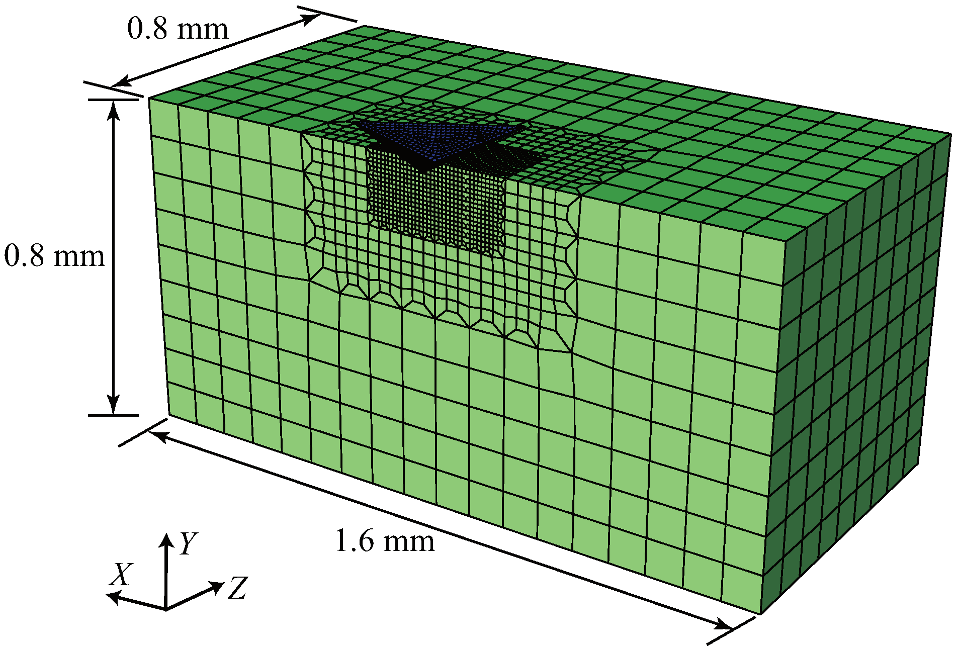
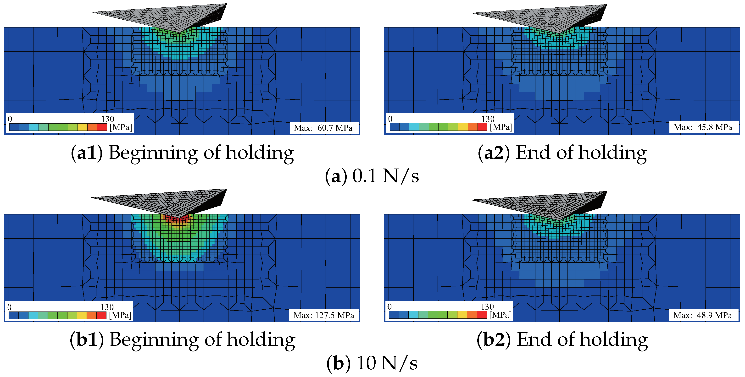
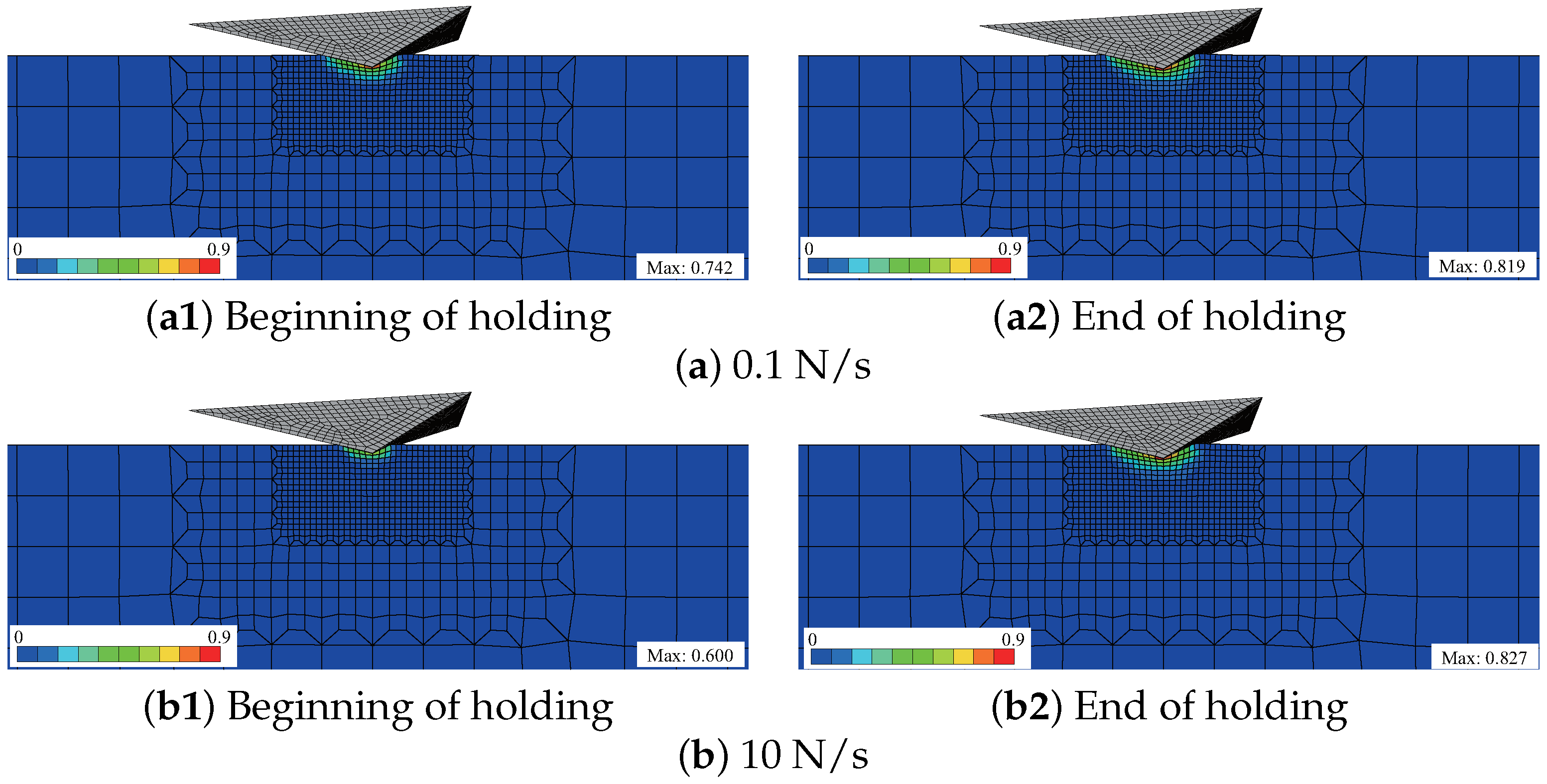
2.2. Finite Element Model of the Instrumented Indentation Test
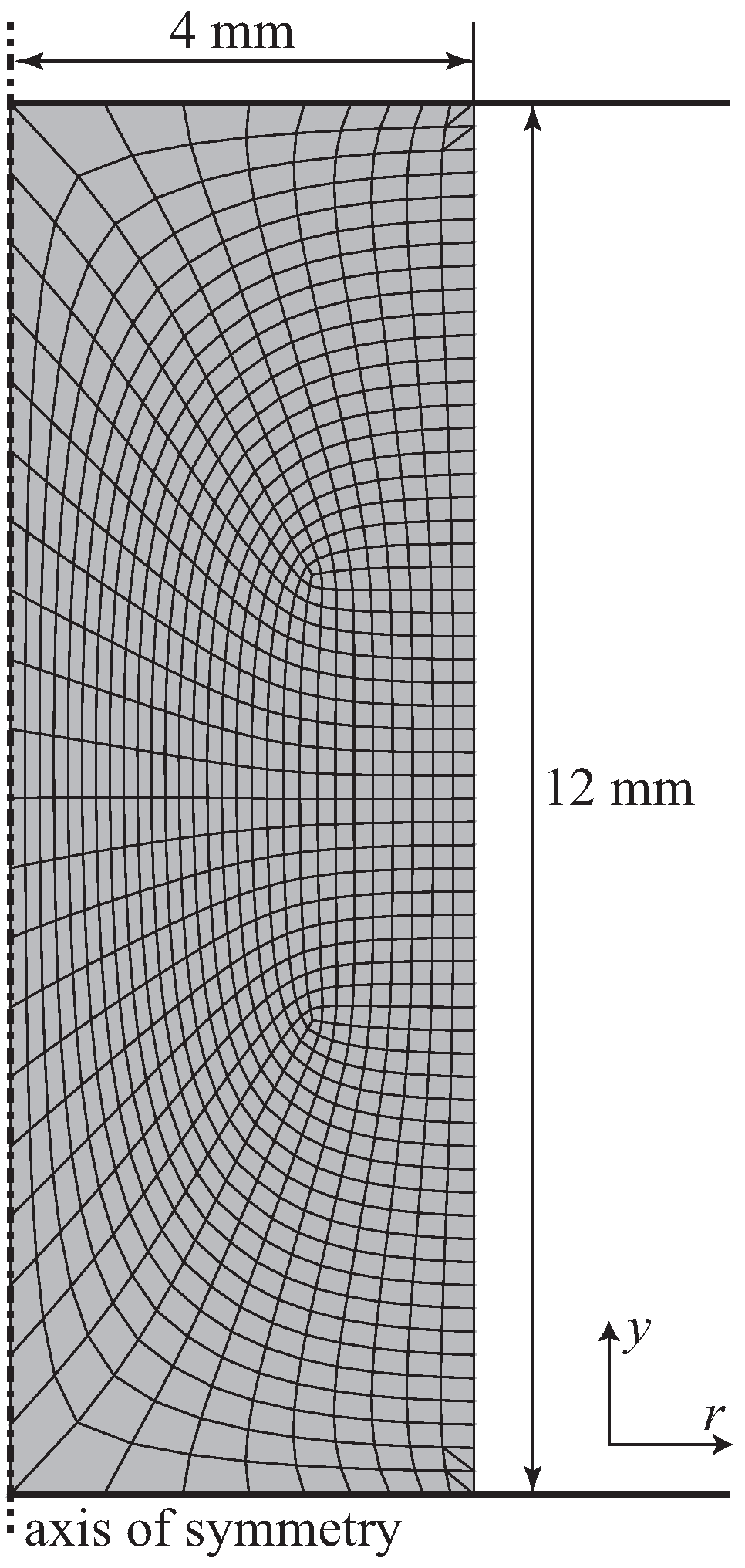
2.3. Finite Element Model of the Compression Test
3. Experiments
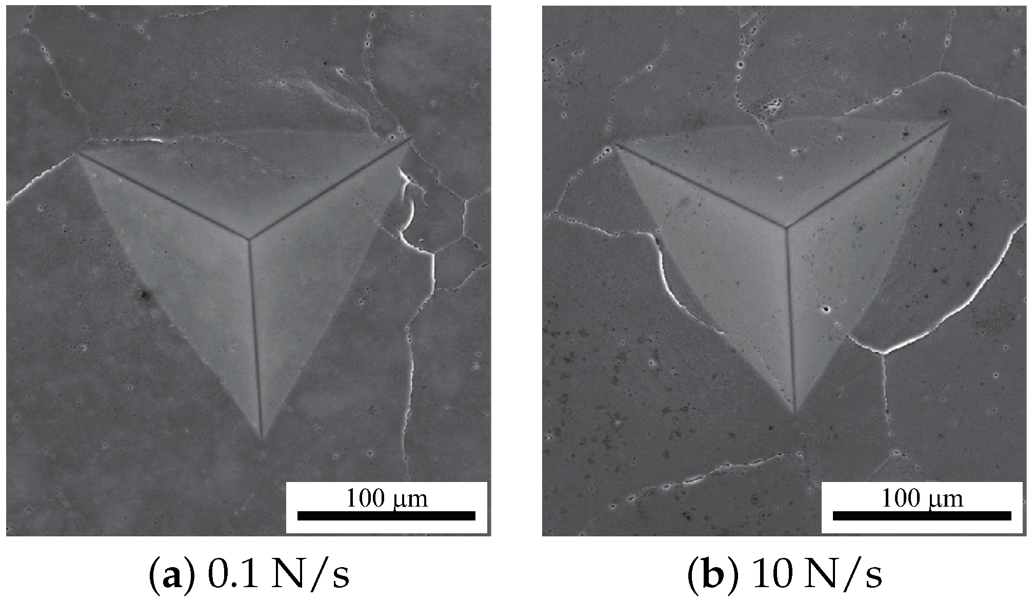
3.1. Specimen
3.2. Instrumented Indentation Tests at High Temperatures
3.2.1. Compression Tests at High Temperatures
4. Characterization of Strain Rate Dependency
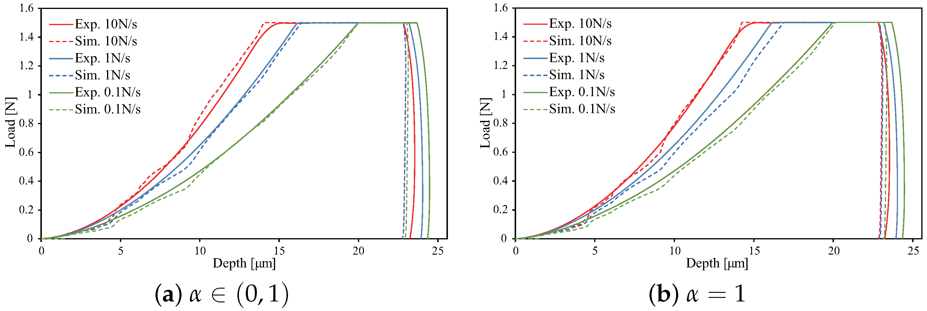
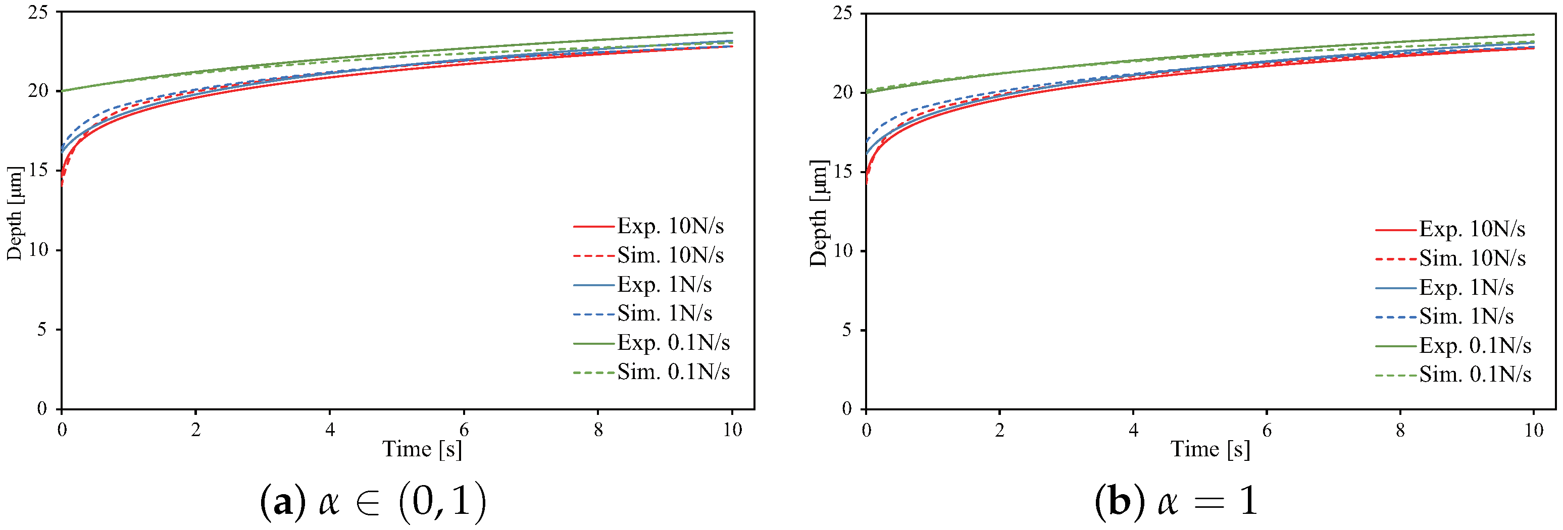
4.1. Determination of Material Constants
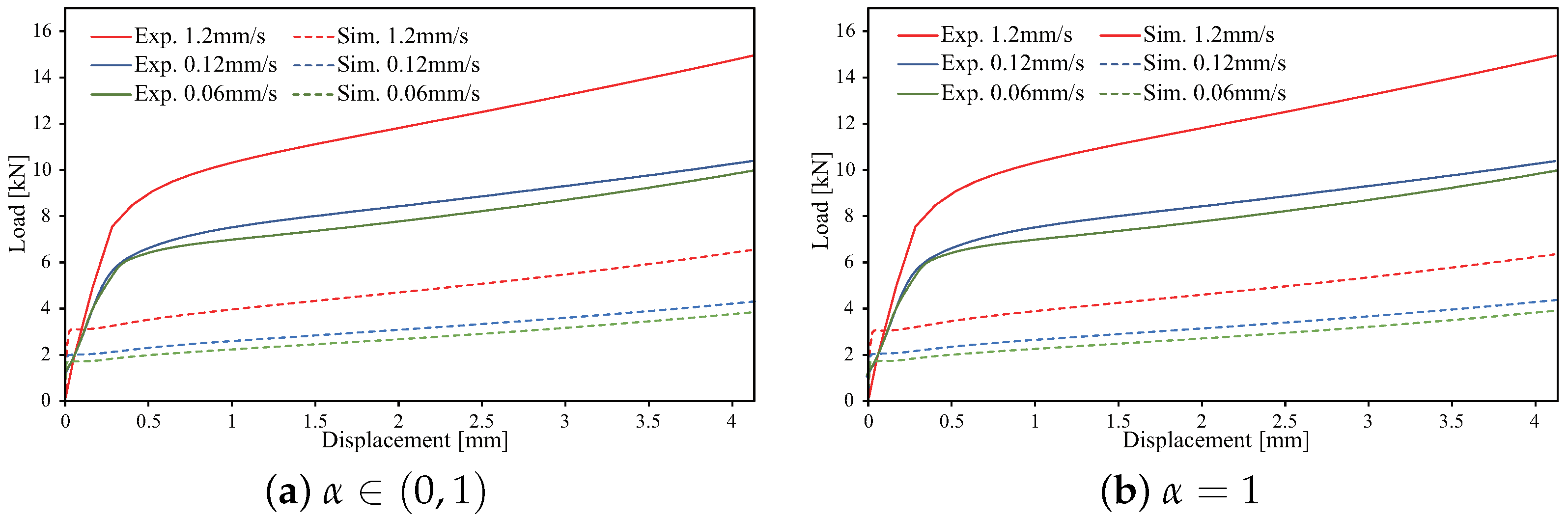
4.2. Validation in Compression Tests
5. Conclusions
Author Contributions
Funding
Institutional Review Board Statement
Informed Consent Statement
Data Availability Statement
Acknowledgments
Conflicts of Interest
References
- Spary, I.; Bushby, A.; Jennett, N.M. On the indentation size effect in spherical indentation. Philos. Mag. 2006, 86, 5581–5593. [Google Scholar] [CrossRef] [Green Version]
- Rester, M.; Motz, C.; Pippan, R. Indentation across size scales–A survey of indentation-induced plastic zones in copper {1 1 1} single crystals. Scr. Mater. 2008, 59, 742–745. [Google Scholar] [CrossRef]
- Fincher, C.D.; Ojeda, D.; Zhang, Y.; Pharr, G.M.; Pharr, M. Mechanical properties of metallic lithium: From nano to bulk scales. Acta Mater. 2020, 186, 215–222. [Google Scholar] [CrossRef]
- Ruzic, J.; Emura, S.; Ji, X.; Watanabe, I. Mo segregation and distribution in Ti–Mo alloy investigated using nanoindentation. Mater. Sci. Eng. A 2018, 718, 48–55. [Google Scholar] [CrossRef]
- Hintsala, E.D.; Hangen, U.; Stauffer, D.D. High-throughput nanoindentation for statistical and spatial property determination. JOM 2018, 70, 494–503. [Google Scholar] [CrossRef] [Green Version]
- Matsuno, T.; Ando, R.; Yamashita, N.; Yokota, H.; Goto, K.; Watanabe, I. Analysis of preliminary local hardening close to the ferrite–martensite interface in dual-phase steel by a combination of finite element simulation and nanoindentation test. Int. J. Mech. Sci. 2020, 180, 105663. [Google Scholar] [CrossRef]
- Li, K.; Injeti, V.; Misra, R.; Cai, Z.; Ding, H. On the strain rate sensitivity of aluminum-containing transformation-induced plasticity steels: Interplay between TRIP and TWIP effects. Mater. Sci. Eng. A 2018, 711, 515–523. [Google Scholar] [CrossRef]
- Man, T.; Ohmura, T.; Tomota, Y. Mechanical behavior of individual retained austenite grains in high carbon quenched-tempered steel. ISIJ Int. 2019, 59, 559–566. [Google Scholar] [CrossRef] [Green Version]
- Man, T.; Ohmura, T.; Tomota, Y. The effect of boundary or interface on stress-induced martensitic transformation in a Fe-Ni alloy. Mater. Today Commun. 2020, 23, 100896. [Google Scholar] [CrossRef]
- Chen, Y.; Hintsala, E.; Li, N.; Becker, B.R.; Cheng, J.Y.; Nowakowski, B.; Weaver, J.; Stauffer, D.; Mara, N.A. High-throughput nanomechanical screening of phase-specific and temperature-dependent hardness in AlxFeCrNiMn high-entropy alloys. JOM 2019, 71, 3368–3377. [Google Scholar] [CrossRef]
- Suzuki, T.; Ohmura, T. Ultra-microindentation of silicon at elevated temperatures. Philos. Mag. A 1996, 74, 1073–1084. [Google Scholar] [CrossRef]
- Ruzic, J.; Watanabe, I.; Goto, K.; Ohmura, T. Nano-indentation measurement for heat resistant alloys at elevated temperatures in inert atmosphere. Mater. Trans. 2019, 60, 1411–1415. [Google Scholar] [CrossRef] [Green Version]
- Ruzic, J.; Goto, K.; Watanabe, I.; Osada, T.; Wu, L.; Ohmura, T. Temperature-dependent deformation behavior of γ and gamma’ single-phase nickel-based superalloys. Mater. Sci. Eng. A 2021, 818, 141439. [Google Scholar] [CrossRef]
- Minnert, C.; Oliver, W.C.; Durst, K. New ultra-high temperature nanoindentation system for operating at up to 1100 °C. Mater. Des. 2020, 192, 108727. [Google Scholar] [CrossRef]
- Chu, S.; Li, J. Impression creep of β-tin single crystals. Mater. Sci. Eng. 1979, 39, 1–10. [Google Scholar] [CrossRef]
- Dean, J.; Bradbury, A.; Aldrich-Smith, G.; Clyne, T. A procedure for extracting primary and secondary creep parameters from nanoindentation data. Mech. Mater. 2013, 65, 124–134. [Google Scholar] [CrossRef]
- Takagi, H.; Dao, M.; Fujiwara, M.; Otsuka, M. Experimental and computational creep characterization of Al–Mg solid-solution alloy through instrumented indentation. Philos. Mag. 2003, 83, 3959–3976. [Google Scholar] [CrossRef]
- Takagi, H.; Dao, M.; Fujiwara, M. Analysis on pseudo-steady indentation creep. Acta Mech. Solida Sin. 2008, 21, 283–288. [Google Scholar] [CrossRef]
- Takagi, H.; Fujiwara, M. Set of conversion coefficients for extracting uniaxial creep data from pseudo-steady indentation creep test results. Mater. Sci. Eng. A 2014, 602, 98–104. [Google Scholar] [CrossRef]
- Fujiwara, M.; Takagi, H.; Higashida, K. High-temperature creep mechanism of dual-ductile-phase magnesium alloy with long-period stacking ordered phase. Mater. Trans. 2019, 60, 503–512. [Google Scholar] [CrossRef] [Green Version]
- Cheng, Y.T.; Cheng, C.M. Can stress–strain relationships be obtained from indentation curves using conical and pyramidal indenters? J. Mater. Res. 1999, 14, 3493–3496. [Google Scholar] [CrossRef] [Green Version]
- Tho, K.K.; Swaddiwudhipong, S.; Liu, Z.S.; Zeng, K.; Hua, J. Uniqueness of reverse analysis from conical indentation tests. J. Mater. Res. 2004, 19, 2498–2502. [Google Scholar] [CrossRef]
- Alkorta, J.; Martinez-Esnaola, J.M.; Sevillano, J.G. Absence of one-to-one correspondence between elastoplastic properties and sharp-indentation load–penetration data. J. Mater. Res. 2005, 20, 432–437. [Google Scholar] [CrossRef]
- Futakawa, M.; Wakui, T.; Tanabe, Y.; Ioka, I. Identification of the constitutive equation by the indentation technique using plural indenters with different apex angles. J. Mater. Res. 2001, 16, 2283–2292. [Google Scholar] [CrossRef] [Green Version]
- Bucaille, J.L.; Stauss, S.; Felder, E.; Michler, J. Determination of plastic properties of metals by instrumented indentation using different sharp indenters. Acta Mater. 2003, 51, 1663–1678. [Google Scholar] [CrossRef]
- Chollacoop, N.; Dao, M.; Suresh, S. Depth-sensing instrumented indentation with dual sharp indenters. Acta Mater. 2003, 51, 3713–3729. [Google Scholar] [CrossRef]
- Taljat, B.; Zacharia, T.; Kosel, F. New analytical procedure to determine stress–strain curve from spherical indentation data. Int. J. Solids Struct. 1998, 35, 4411–4426. [Google Scholar] [CrossRef]
- Ahn, J.H.; Kwon, D. Derivation of plastic stress–strain relationship from ball indentations: Examination of strain definition and pileup effect. J. Mater. Res. 2001, 16, 3170–3178. [Google Scholar] [CrossRef]
- Swadener, J.; Taljat, B.; Pharr, G. Measurement of residual stress by load and depth sensing indentation with spherical indenters. J. Mater. Res. 2001, 16, 2091–2102. [Google Scholar] [CrossRef]
- Goto, K.; Watanabe, I.; Ohmura, T. Determining suitable parameters for inverse estimation of plastic properties based on indentation marks. Int. J. Plast. 2019, 116, 81–90. [Google Scholar] [CrossRef]
- Goto, K.; Watanabe, I.; Ohmura, T. Inverse estimation approach for elastoplastic properties using the load-displacement curve and pile-up topography of a single Berkovich indentation. Mater. Des. 2020, 194, 108925. [Google Scholar] [CrossRef]
- Duan, Y.; Xu, J.; Chen, J.; Yu, C.; Chen, J.; Lu, H. The effects of heat treatment on the microstructure and cyclic behavior of A7N01-T4 aluminum alloy. Mater. Charact. 2017, 131, 201–209. [Google Scholar] [CrossRef]
- Chen, T.; Watanabe, I.; Liu, D.; Goto, K. Data-driven estimation of plastic properties of alloys using neighboring indentation test. Sci. Technol. Adv. Mater. Methods 2021, 1, 143–151. [Google Scholar]
- Simmons, G.; Wang, H. Single Crystal Elastic Constants and Calculated Aggregate Properties; MIT Press: Cambridge, MA, USA, 1971. [Google Scholar]
- Marquardt, D.W. An algorithm for least-squares estimation of nonlinear parameters. J. Soc. Ind. Appl. Math. 1963, 11, 431–441. [Google Scholar] [CrossRef]
- Lüthy, H.; White, R.A.; Sherby, O.D. Grain boundary sliding and deformation mechanism maps. Mater. Sci. Eng. 1979, 39, 211–216. [Google Scholar] [CrossRef]
- Cipoletti, D.E.; Bower, A.F.; Qi, Y.; Krajewski, P.E. The influence of heterogeneity in grain boundary sliding resistance on the constitutive behavior of AA5083 during high-temperature deformation. Mater. Sci. Eng. A 2009, 504, 175–182. [Google Scholar] [CrossRef]


| Zn | Mg | Zr | Cu | Fe | Si | Ti |
|---|---|---|---|---|---|---|
| 5.60 | 1.34 | 0.16 | 0.15 | 0.03 | 0.02 | 0.02 |
Publisher’s Note: MDPI stays neutral with regard to jurisdictional claims in published maps and institutional affiliations. |
© 2021 by the authors. Licensee MDPI, Basel, Switzerland. This article is an open access article distributed under the terms and conditions of the Creative Commons Attribution (CC BY) license (https://creativecommons.org/licenses/by/4.0/).
Share and Cite
Chen, T.-T.; Watanabe, I.; Funazuka, T. Characterization of the Strain-Rate-Dependent Plasticity of Alloys Using Instrumented Indentation Tests. Crystals 2021, 11, 1316. https://doi.org/10.3390/cryst11111316
Chen T-T, Watanabe I, Funazuka T. Characterization of the Strain-Rate-Dependent Plasticity of Alloys Using Instrumented Indentation Tests. Crystals. 2021; 11(11):1316. https://doi.org/10.3390/cryst11111316
Chicago/Turabian StyleChen, Ta-Te, Ikumu Watanabe, and Tatsuya Funazuka. 2021. "Characterization of the Strain-Rate-Dependent Plasticity of Alloys Using Instrumented Indentation Tests" Crystals 11, no. 11: 1316. https://doi.org/10.3390/cryst11111316
APA StyleChen, T.-T., Watanabe, I., & Funazuka, T. (2021). Characterization of the Strain-Rate-Dependent Plasticity of Alloys Using Instrumented Indentation Tests. Crystals, 11(11), 1316. https://doi.org/10.3390/cryst11111316