Abstract
Polyetheretherketone (PEEK) has been the focus of substantial additive manufacturing research for two principal reasons: (a) the mechanical performance approaches that of aluminum at relatively high temperatures for thermoplastics and (b) the potential for qualification in both the aerospace and biomedical industries. Although PEEK provides outstanding strength and thermal stability, printing can be difficult due to the high melting point. Recently, high-temperature soluble support has enabled the printing of lattices and stochastic foams with overhanging features in these high-performance carbon fiber thermoplastics, in which density can be optimized to strike a balance between weight and strength to enhance performance in applications such as custom implants or aerospace structures. Although polymer powder bed fusion has long been capable of the combination of these geometries and materials, material extrusion with high-temperature sacrificial support is dramatically less expensive. This research provides a comprehensive mechanical analysis and CT-scan-based dimensional study of carbon fiber PEEK lattice structures enabled with high-temperature support and including model validation.
1. Introduction
Poly (ether-ether-ketone) (PEEK) is a melt-processable semi-crystalline engineering polymer that transforms from amorphous in its melt state to crystalline structure during the solidification process. PEEK displays high strength, stability, stiffness, and high-temperature performance. These engineering-grade thermoplastics, when formed with traditional methods, can potentially replace non-ferrous metals (such as aluminum) in some applications, providing high wear resistance and low friction coefficient benefits [1,2]. Furthermore, these thermoplastics are flame-, smoke- and toxicity-qualifiable materials, making them most sought out in industries such as aerospace, electronics, automotive, health care, oil and marine [3,4,5,6,7,8,9]. PEEK has a high thermal degradation resistance with a continuous working temperature of up to 260 °C and a melting point of 343 °C [10,11,12,13]. Since the 1980s, PEEK has been used for medical applications such as orthopedics and dentistry [14,15,16,17,18,19,20,21,22,23,24].
Although the properties and performance of these thermoplastics have been well- studied in the context of traditional forming methods, the use of 3D printing requires further investigation in order to fabricate geometrically complex high-performance structures. The limitations of manufacturing these polymers include shrinkage due to crystallization [25,26] and high melting temperatures. Given these difficulties, reports of additively manufactured (AM) PEEK have been performed on extrusion printers [27,28] and by powder bed fusion [29,30]. It has also been determined that extrusion printers offer a more economical solution compared to powder bed fusion for manufacturing lightweight structures. Investigations of optimal PEEK printing parameters have been performed to avoid warping with the nozzle and chamber temperatures of 400 °C and 130 °C, respectively. An investigation on the influence of thermal post-processing on printed PEEK structures highlighted that the tensile strength strongly depends on the post-thermal treatments [31].
Three-dimensionally printed PEEK was found to have tensile strength of 56.6 MPa with compressive strength of 60.9 MPa and compressive modulus of 0.7 GPa, and the flexural strength and modulus were determined to be 56.2 MPa and 1.6 GPa [32]. In contrast, additive manufactured CF-PEEK was reported to have tensile strength of 125 MPa, tensile modulus of 4.1 GPa [33], flexural strength of 519.2 MPa and flexural modulus of 26.9 GPa [34]. The increase in the mechanical properties of PEEK vs. CF-PEEK could be attributed to the addition of the carbon fibers, which have been known to enhance material properties. Consequently, carbon fibers have been included as fillers to reinforce the polymers’ feedstock for additive manufacturing [35]. This has dramatically improved their mechanical performance such as strength, stiffness and fatigue [36,37]. Beyond PEEK, poly-ether-ketone-ketone (PEKK) is also of interest in additive manufacturing. PEKK can serve in many applications due to the flexibility in tuning the melting temperature, crystallinity and crystallization rate [38]. After conducting thermal and rheological analysis and impact tests, PEKK was demonstrated to be printed at large scales [39]. Three-dimensionally printed PEKK reported tensile strength of 90.6 MPa, tensile modulus of 2.92 GPa, compressive strength of 97.5 MPa and compressive modulus of 2.36 GPa [40]. The flexural strength and modulus were reported to be 127 MPa and 2.72 GPa, respectively [41]. On the other hand, CF-PEKK had a tensile modulus of 2.9 GPa and a flexural modulus of 3 GPa, which depends on the number of fibers and their size [42]. In a study conducted by Fischer, the mechanical properties of PEKK were found to be enhanced by adding carbon fibers in a laser sintering system [43].
In the current contribution, complex lattice structures were fabricated using high performance PEEK- and PEKK-based thermoplastics with the benefit of soluble support material formulated to be compatible with the printing of engineering-grade, high-temperature filament. Tensile, flexural and compression testing were completed on standard coupons and low-velocity impact tests were performed on lattices which included internal features with long overhanging spans. Lattices in additive manufacturing often require sacrificial support material for features such as overhangs and bridges [44]. Dimensional compliance was evaluated using a CT scan. Finally, ANSYS simulations were performed and were in good agreement with the experimental results, and consequently, the design space of a wide range of potential lattice architectures can be explored virtually to optimize the balance between strength and weight for specific biomedical or aerospace applications. This simulation platform can be further used to explore the mechanical performance of additional configurations without the need to run experimental testing.
2. Materials and Methods
2.1. Feedstock Material
This work studied the mechanical performance of four different 3D-printed systems of the polyaryletherketone (PAEK) family: amorphous PEEK (labeled as “PEEK” in this work), PEKK, semi-crystalline PEEK (SCP) and carbon fiber PEEK (CF-PEEK). The build material used commercially available off-the-shelf PEEK, PEKK and CF-PEEK filaments, with 1.75 mm diameter. The thermal characteristics of the investigated material have been extensively reported [38,45,46,47]. PEEK has a glass transition temperature of 143 °C and a melting point of 343 °C. Similarly, PEKK material has a glass transition temperature of 165 °C and melts at 300 °C. CF-PEEK material displays a Tg at 150 °C and a Tm at 340 °C.
2.2. Printing Process
A 3DGence Industry F420 fused filament fabrication (FFF) unit was used to print the PAEK materials. The printer used in this study featured fully enclosed heated chambers capable of reaching over 180 °C, which is required to provide a stable temperature environment to print PAEK structures. The printer also features a dual-nozzle printhead system to print at temperatures ranging from 190 to 500 °C. The dual-nozzle modules printed the primary high-temperature build materials as well as a sacrificial support material. Both printheads used stainless steel nozzles 0.4 mm in diameter. The infill was set as 100%, layer thickness at 0.15 mm, and printing process parameters as presented in Table 1.

Table 1.
Printing process parameters.
Support material used in this effort was a styrene-acrylic copolymer. The material dissolves in alkaline solutions of 11–12 pH, leaving no residue after 3 h. The mode of operation is based on converting anhydrides to acids and polymer chain disintegration by dissociation. The exact reason for styrene-acrylic or similar support material compatibility to the PAEK family of polymers is still under investigation, but ample anecdotal evidence suggests that sufficient bonding occurs. Without soluble support, the range of geometries would be significantly limited for these high-temperature thermoplastics. Here, a hexagonal lattice was printed with and without support to emphasize the necessity of sacrificial support in printing complex structures with overhanging features.
2.3. X-ray Computed Tomography (CT Scan) for Geometry Compliance
X-ray CT scanning was completed with a GE Nanotom S system at the Stellenbosch CT facility in South Africa [48]. The entire sample was scanned at 100-micron voxel size, with X-ray settings of 100 kV and 150 μA using 3000 projection images, acquired at 500 ms each (in one full rotation of the sample). Reconstruction was completed with a GE Datos 2.3 and visualization was performed in Volume Graphics VGSTUDIO MAX 3.3.1.
2.4. Mechanical Testing Coupons and Methods
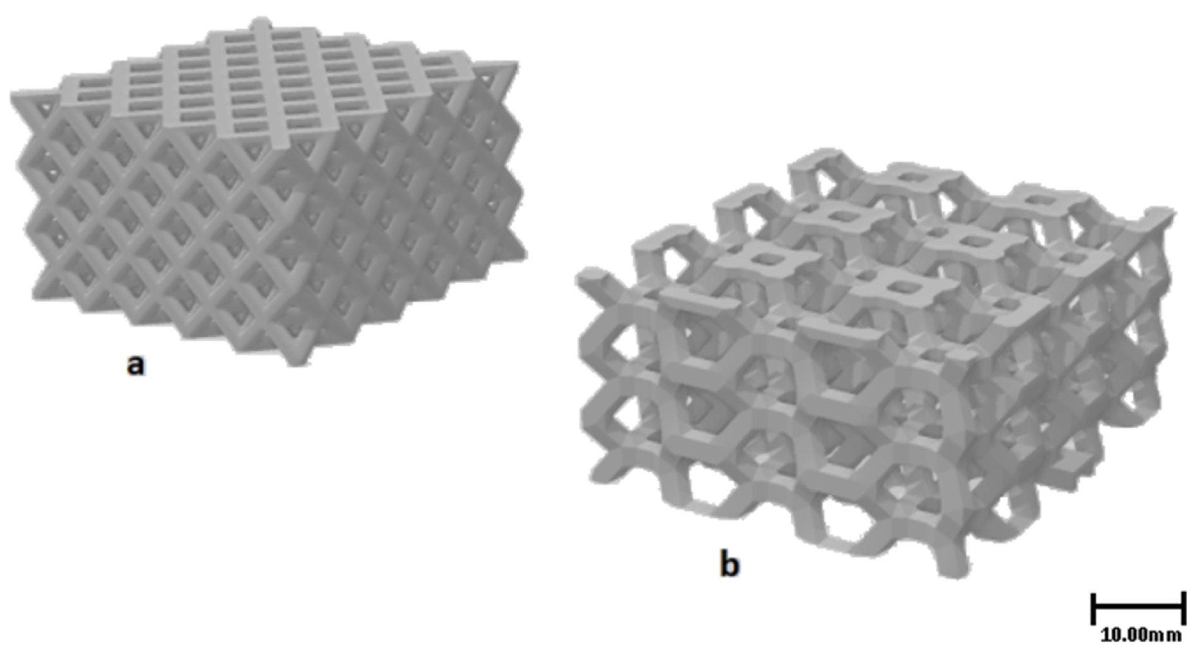
In this work, the dimensions and testing setup of the lattice flexural specimens were based on the work performed by Li and Wang [49], while the compression lattice specimens followed the ASTM D1621 standard, and the tensile specimens the ASTM D638. All tests were performed on an Instron 5500 R. A previous study on various lattice structures was completed in [50], in which the mechanical performance was compared among different architectures, and the octet lattice demonstrated a promising stretching-dominated behavior (Figure 1a). Figure 1b shows the hexagonal lattice with long unsupported spans to highlight the need for sacrificial support. A tensile test was performed only on the carbon fiber PEEK system to evaluate the fundamental mechanical properties to support the FEA modeling. The carbon fiber PEEK was selected for modeling due to the outstanding ductility observed during preliminary testing.

Figure 1.
(a) Three-dimensionally printed lattices investigated in this work: octet design for compression and flexural testing. (b) Hexagonal design with long unsupported spans for studying the utility of soluble supporting material.
2.5. Mechanical Modeling
Numerical simulations of carbon fiber PEEK were performed using ANSYS® (version 19.2, ANSYS, Canonsburg, PA, USA), a commercial finite element analysis (FEA) software, to evaluate the fitting of the material to a multilinear isotropic hardening (MISO) model and to reproduce the results of the experimental tensile and compression tests. A MISO model considers a uniaxial case of loading through a piecewise stress–strain curve, which starts from the origin and has positive stress and strain values. MISO assumes that an element is composed of several segments with common total strain and modulus of elasticity, which differs according to each yield strength segment [51,52,53]. Thus, the observed tensile behavior for each printing direction is fitted to sets of modulus elasticity, yield strength and stress–plastic strain listed in Table 2. The first simulation considered a CAD model of the D638 Type IV tensile test specimen generated and imported into ANSYS®, where the MISO material model with the mechanical properties listed in Table 2 were used. Boundary conditions included one end of the specimen fully restricted while the remaining end had a displacement aligned with the centerline of the specimen to track it.
Table 2.
Mechanical properties of carbon fiber PEEK fitted to an isotropic-hardened material model for simulations with ANSYS FEA.
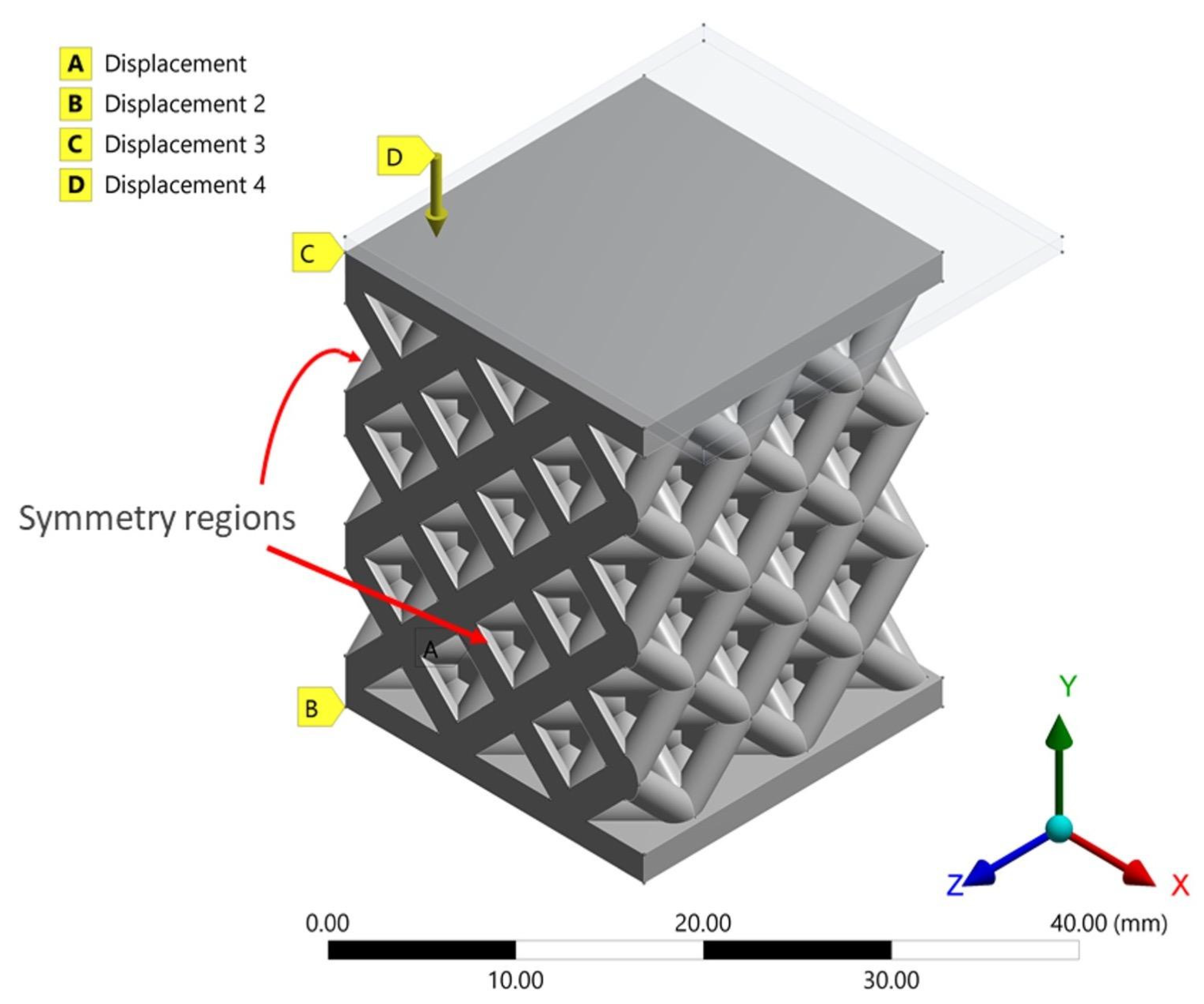
The second numerical simulation included the geometry of the octahedral lattice, which was built and imported into ANSYS®. In this case, symmetry conditions were imposed to reduce computing time. Other boundary conditions included displacement restrictions to the bottom surface and a downward displacement of the top body to generate a 50% compression of the lattice (see Figure 2). Moreover, the mechanical properties and material model described for the Z printing direction case were here defined (see Table 2).

Figure 2.
Symmetric geometry and boundary conditions for the lattice specimens.
3. Results and Discussion
A series of mechanical tests were performed to demonstrate the applicability of a myriad of applications possible for the materials studied in this research work. Additionally, the use of recent and commercially available sacrificial soluble support has broadened the geometries that are now possible. Through CT scanning, the improvement in dimensional compliance with the addition of high-temperature support material was demonstrated.
3.1. Computer Tomography to Evaluate Geometrical Compliance
Compliance to the intended geometries was evaluated using a CT scan as shown in Figure 3. The lattices included long unsupported spans which, without support material, can cause printability problems. In the CT scan image in Figure 3a, the lattice was printed with support material and the down-facing surfaces are well-defined. However, the image in Figure 3b highlights defects in red, as drooping occurred during filament extrusion without soluble supports. As some fraction of the material on these bridges was detached from the lattice, an unintentional decrease in the cross-section occurred and mechanical performance was expected to be reduced. For more pathological geometries with long bridging or overhanging features, the structures may not be possible to fabricate at all without the benefit of high-temperature support material. A video flythrough is included here of the CT scan, which clearly shows the challenges of the down-facing surfaces printed without support.
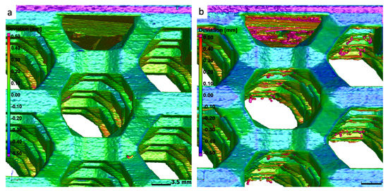
Figure 3.
(a) Lattice with supports and (b) without supports. Red coloring indicates geometry error approaching and exceeding positive deviation of 0.5 mm. Unsupported spans are as long as 7 mm on the down-facing surfaces for this structure. Drooping is evident without support.
3.2. Mechanical Properties
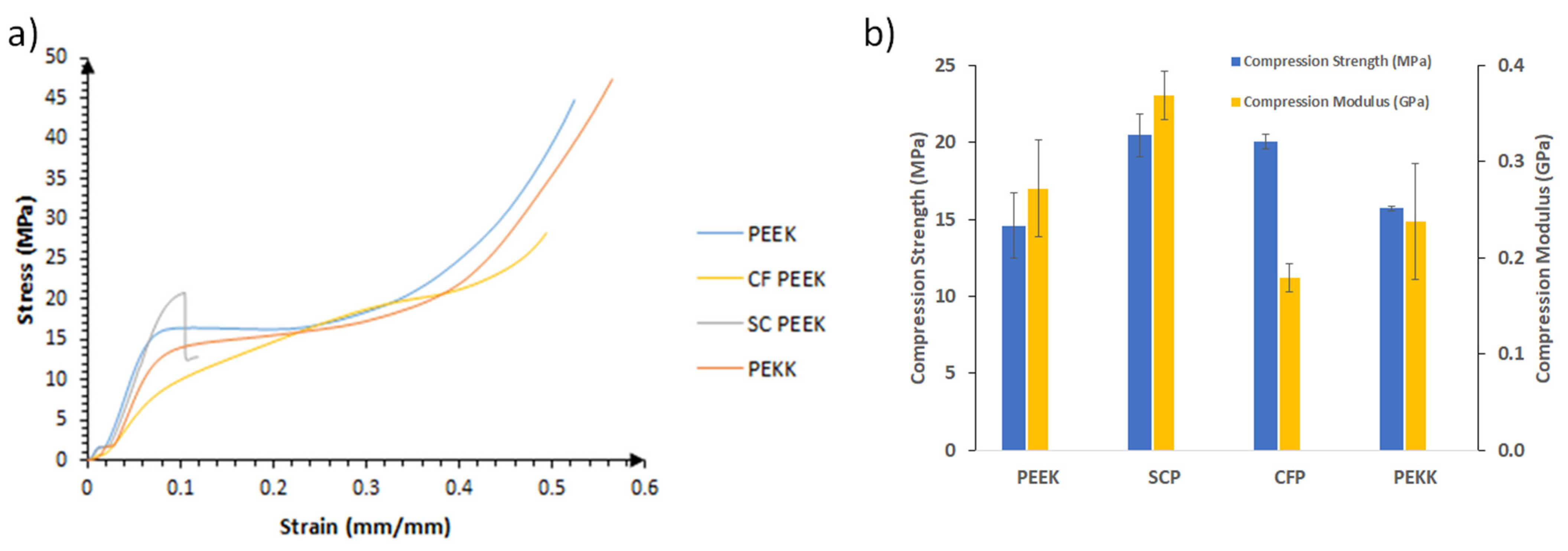
Compression and flexural tests were performed on lattice structures based on the octet unit cell using the amorphous PEEK, semi-crystalline PEEK, carbon fiber PEEK and PEKK. Figure 4 shows the stress–strain curves of the compressed lattice structures, where the degree of densification on the amorphous PEEK, CF-PEEK, and PEKK is observed. From the figure, the lack of ductility of the semi-crystalline PEEK when compared to the other materials is clearly observed. Figure 4 also summarizes the compressive strength and modulus of the four investigated materials. The semi-crystalline PEEK resulted in the highest strength and modulus, a mechanism associated with the stronger and stiffer effect of the spherulites in the polymeric structure [31,54].
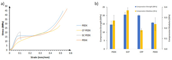
Figure 4.
(a) Stress–strain of the investigated lattices under compression conditions. (b) Compressive strength and modulus of the lattice structures investigated based on four different PAEK constituents: amorphous PEEK, semi-crystalline PEEK, carbon fiber PEEK and PEKK.
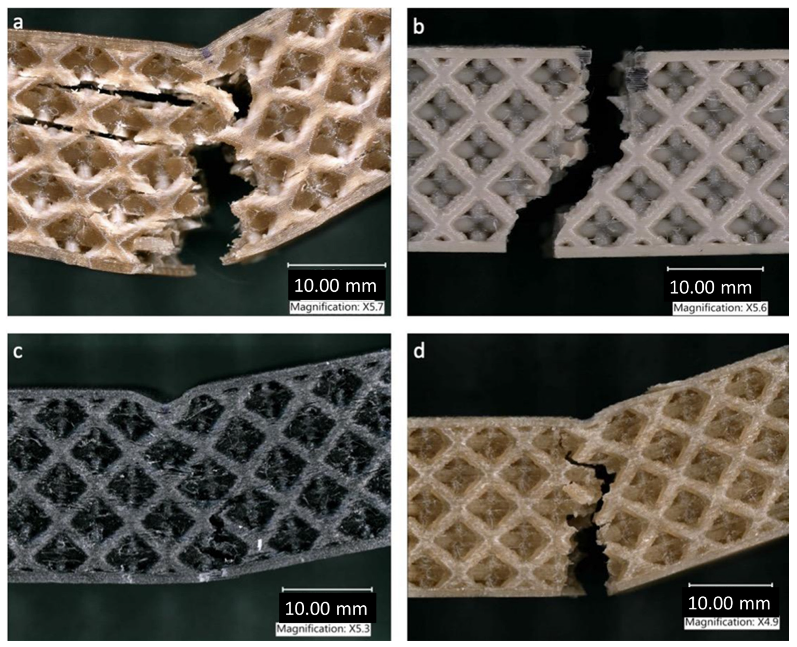
The fracture profile of the lattices following the compression testing is shown in Figure 5, where the ductility features of the amorphous PEEK are observed. Because of lack of crystallinity in the structure, the PEEK lattices reach the densification point without a visible fracture as shown in Figure 5a,c [54]. In contrast, the semi-crystalline PEEK displays a clear failure across the lattice struts as shown in Figure 5b. Figure 5c also shows the compressive profile of the carbon fiber PEEK lattice, where a large degree of plasticity is observed. This ductility could be associated with the amorphous constitution of the system and probably with the incorporation of additives within the carbon fibers. Compression of PEKK lattice structures has resulted in the crack propagation within the struts of the walls of the structure, as shown in Figure 5d.
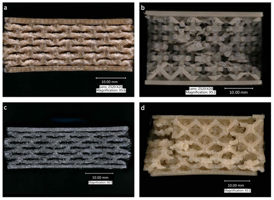
Figure 5.
Optical microscope images of the lattice structures samples after compression testing. (a) Amorphous PEEK, (b) semi-crystalline PEEK, (c) carbon fiber PEEK and (d) PEKK.
The flexural results of the investigated lattices are shown in Figure 6. Here, PEKK, amorphous PEEK and carbon fiber PEEK have similar flexural strength and modulus. The lowest flexural strength was recorded on the semi-crystalline PEEK, with a strength lower than 20 MPa. This unexpected result is the subject of future work. It could be theorized that the lower strength could be associated with a sensitivity under the tensile condition faced at the bottom section of the flexural testing. This susceptibility could have induced an initial fracture on the lower face of the specimen followed by catastrophic rupture through the entire specimen. In contrast, its high degree of crystallinity resulted in the highest flexural modulus among the different materials investigated.
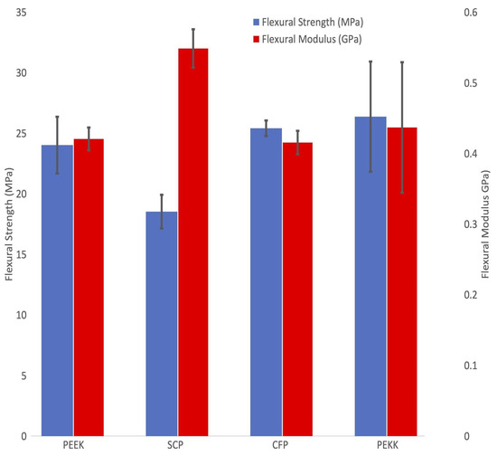
Figure 6.
Flexural strength and modulus of the lattice structures investigated based on four different PAEK systems.
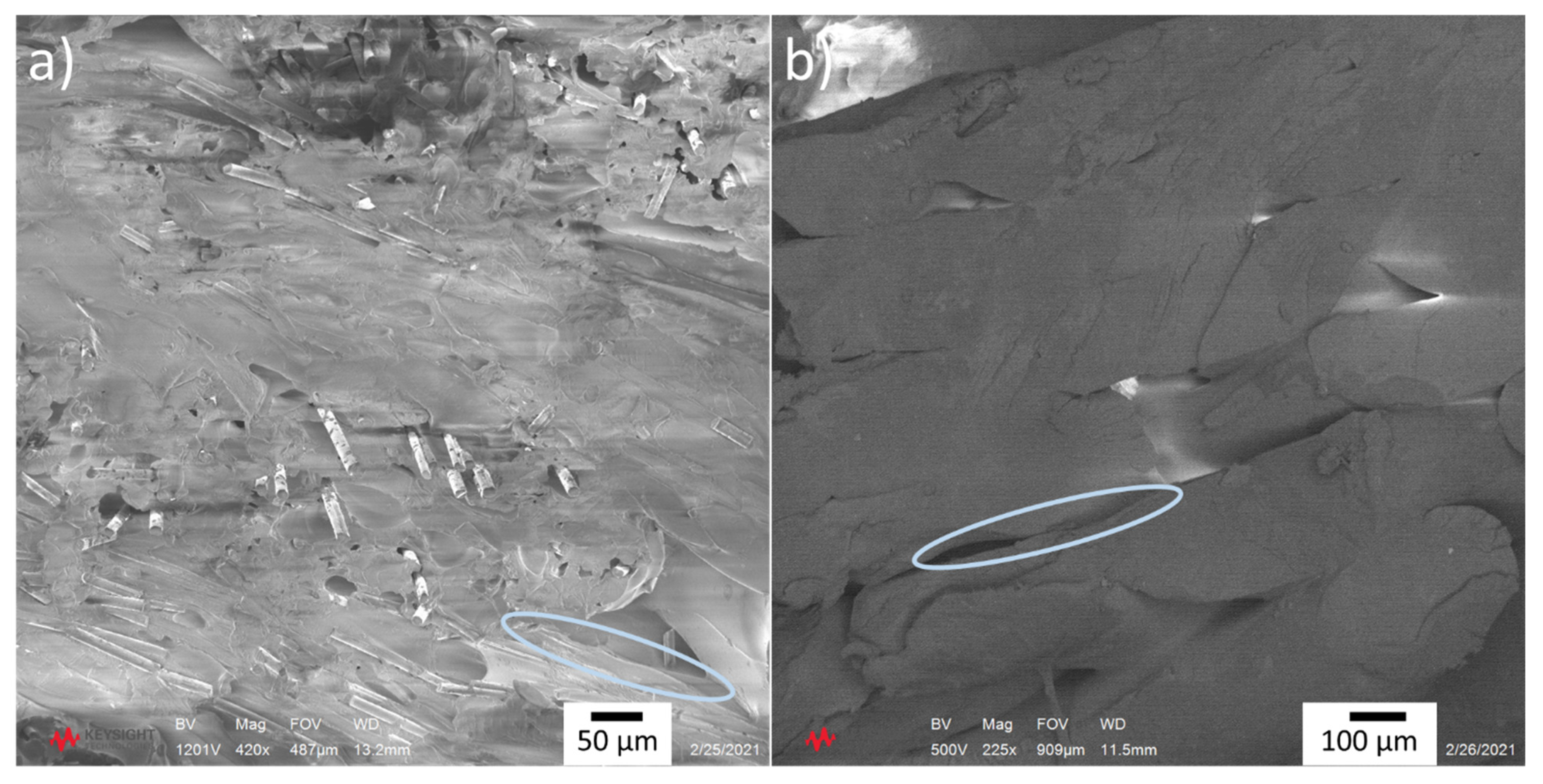
Figure 7 shows the lattice materials after the flexural testing. The samples highlight that the flexural performance is governed by the tensile section of the specimens. It is interesting to observe that the amorphous PEEK and PEKK shown in Figure 7a,d display a similar fracture mechanism, with the crack initiating on the opposite face and propagating towards the loading point. The strength and modulus are also similar. As in the case of the compression testing, the benefit of the PEKK could be associated with its performance at higher temperatures and characteristic of higher shock absorbance compared to PEEK. Figure 7c also shows the similar yielding fracture profile on the carbon fiber PEEK and semi-crystalline PEEK systems. These fracture modes were also observed in the samples subjected to the flexural testing under a SEM. Figure 8 images illustrate that the carbon fiber PEEK displays a ductile ploughing fracture mechanism. Similarly, the sample shows a high degree of fiber–matrix adhesion. No fiber pull-out is observed; in fact, the carbon fibers remain attached to the matrix, with a fracture across their cross-sectional area.

Figure 7.
Optical micrographs of the fractured flexural specimens. (a) Amorphous PEEK, (b) semi-crystalline PEEK, (c) carbon fiber PEEK and (d) PEKK.
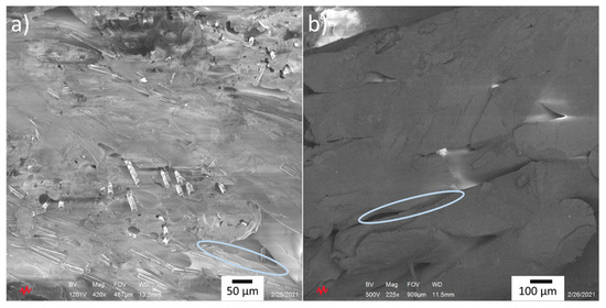
Figure 8.
SEM images of fractured flexural samples for (a) Carbon fiber PEEK and (b) semi-crystalline PEEK. Included in the figure are the markings highlighting the ductile and brittle profile of the materials.
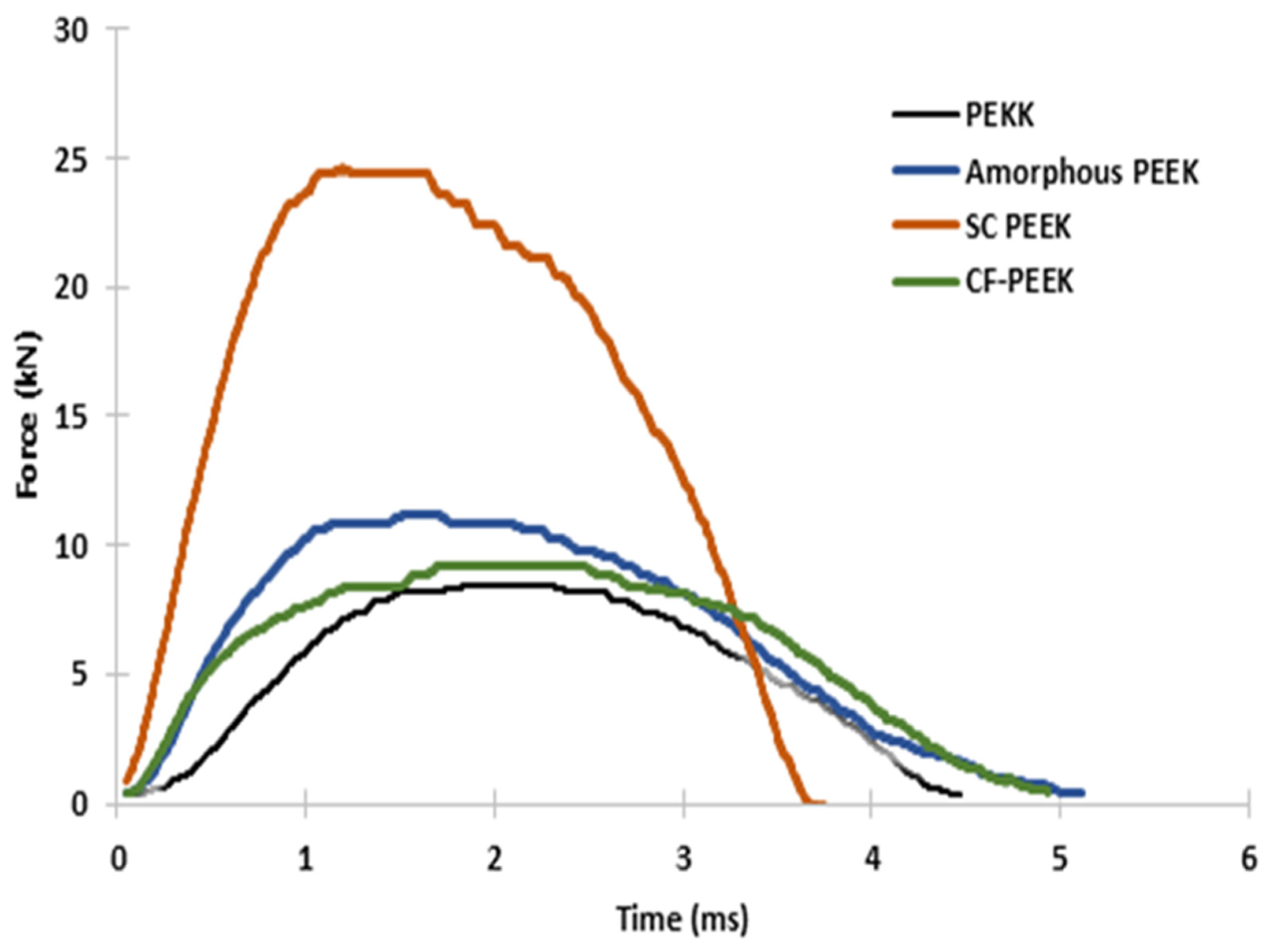
Based on the quasi-static mechanical results, preliminary impact testing is underway on the investigated materials, particularly on the carbon fiber PEEK and PEKK materials. A falling-weight impact tower with a 50 kN Kistler load cell was used to conduct low-velocity impact tests. To induce different impact energies, an impactor mass of 16 kg was dropped from different heights. The samples were placed at the bottom of the impact tower and hit by a flat hemispherical impactor of 15.7 mm diameter. The impacts performed in the tests were with energy increments and then correlated to the changes observed in the force–time curves with the damage exhibited on each material. A high-speed video camera was used to record the impact and velocities of about 1.7 m/s were recorded, representing an impact energy of about 25 J. Figure 9 shows the recorded data from the load cell, where it is observed that the semi-crystalline PEEK displays a large impact force of about 25 kN. This resulted in about 16 J of absorbed energy when the displacement data from the video camera was incorporated in the calculations, representing about 62% of the impact energy. Additional impact events at superior energies resulted in a total destruction of the samples. In contrast, the PEKK, amorphous PEEK and carbon fiber PEEK absorbed between 31% and 40% of the impact energy. This suggests that with the exception of the SC-PEEK, the other systems are still capable of supporting higher impact energies before reaching their fracture points. Figure 10 shows the impact event of the CF-PEEK lattice under 25 J. It is observed that the part shows some degree of buckling on the unit cell at the bottom of the structure. However, the system seems to recover most of its original conformation, since only 0.8 mm of residual displacement was recorded on the sample.
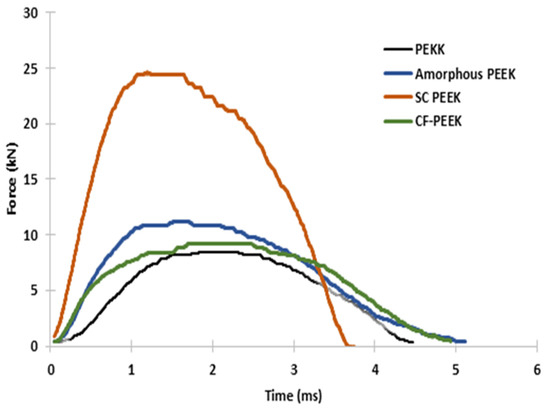
Figure 9.
Force–time plots of the impacted samples under 25 J at velocities of about 1.7 m/s.
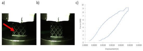
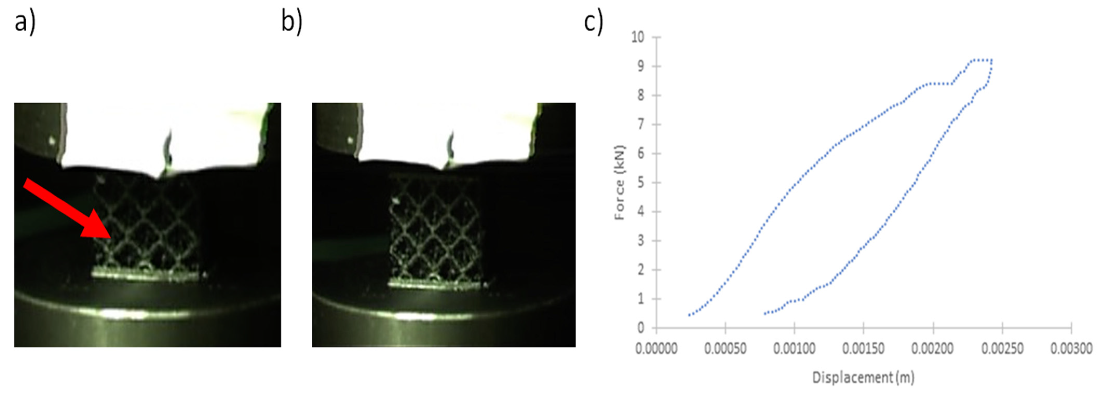
Figure 10.
Impact event of the CF-PEEK lattice structure. (a) Deformation of the lattice inducing a buckling mechanism shown by the arrow in the unit cells at the maximum deformation; (b) recovery of sample after the impact test, showing a high degree of elasticity; (c) force–displacement curve showing the limited residual displacement induced on the lattice structure.
The impact testing is still under investigation to explore the optimal impact properties of these high-temperature materials produced with soluble supporting materials. A full manuscript will be submitted displaying the detailed procedure and results. Considering the quasi-static mechanical tests and the preliminary impact results, simulation work was performed on the CF-PEEK system, due to its ability to withstand high mechanical and impact forces and its use on structural applications under high-temperature conditions. With the high-fidelity modeling foundation here studied, a diversity of lattices and stochastic foams—now possible to fabricate with sacrificial support material—can be evaluated virtually to reduce the duration of the overall design and prototype cycle.
3.3. Simulation Results of Carbon Fiber PEEK
The numerical simulation of carbon fiber PEEK lattices under compressive conditions was carried out in ANSYS® 19.2. The simulations were performed once a confidence in the simulation modeling was established. Here, the initial model evaluation was performed on solid tensile bars experimentally evaluated under quasi-static conditions. The tensile strength analysis for carbon fiber PEEK was performed for three different print orientations: the x- (with a 45° infill), y- and z-axes, with three samples per orientation, which were found to be 51.12 (±0.75) MPa, 80.94 (±0.25) MPa and 40.64 (±5.56) MPa, respectively. In this evaluation procedure, three samples for each printed direction were tested for determining the tensile strength. As expected, the value for the z-axis displays the lowest strength due to the anisotropy associated with the 3D printing. Further heat treatment optimizations for the z-axis are being investigated to enhance the strength in this direction. The highest strength resulted from the y-axis, where the printing was aligned to the tensile direction. It has been widely reported that the alignment of the carbon fibers in conjunction with the polymer chains yields the highest mechanical strength on longitudinally oriented 3D-printed parts [55,56]. The failure micrographs of the fractured tensile carbon fiber PEEK samples are shown in Figure 11. The specimens show that the coupons printed in the x- and y-directions display a higher degree of plasticity than the z-orientation. The figure includes the stress–strain plots of the CF-PEEK system printed in the three different orientations, where it observes the brittle profile of the samples printed in the z-direction.
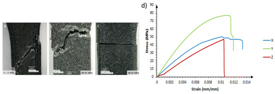
Figure 11.
Micrograph of carbon fiber PEEK tensile bars with their respective tensile strength for (a) x-axis with 45° infill, (b) y-axis and(c) z-axis. Included in the figure are the (d) stress–strain curves of the carbon fiber PEEK.
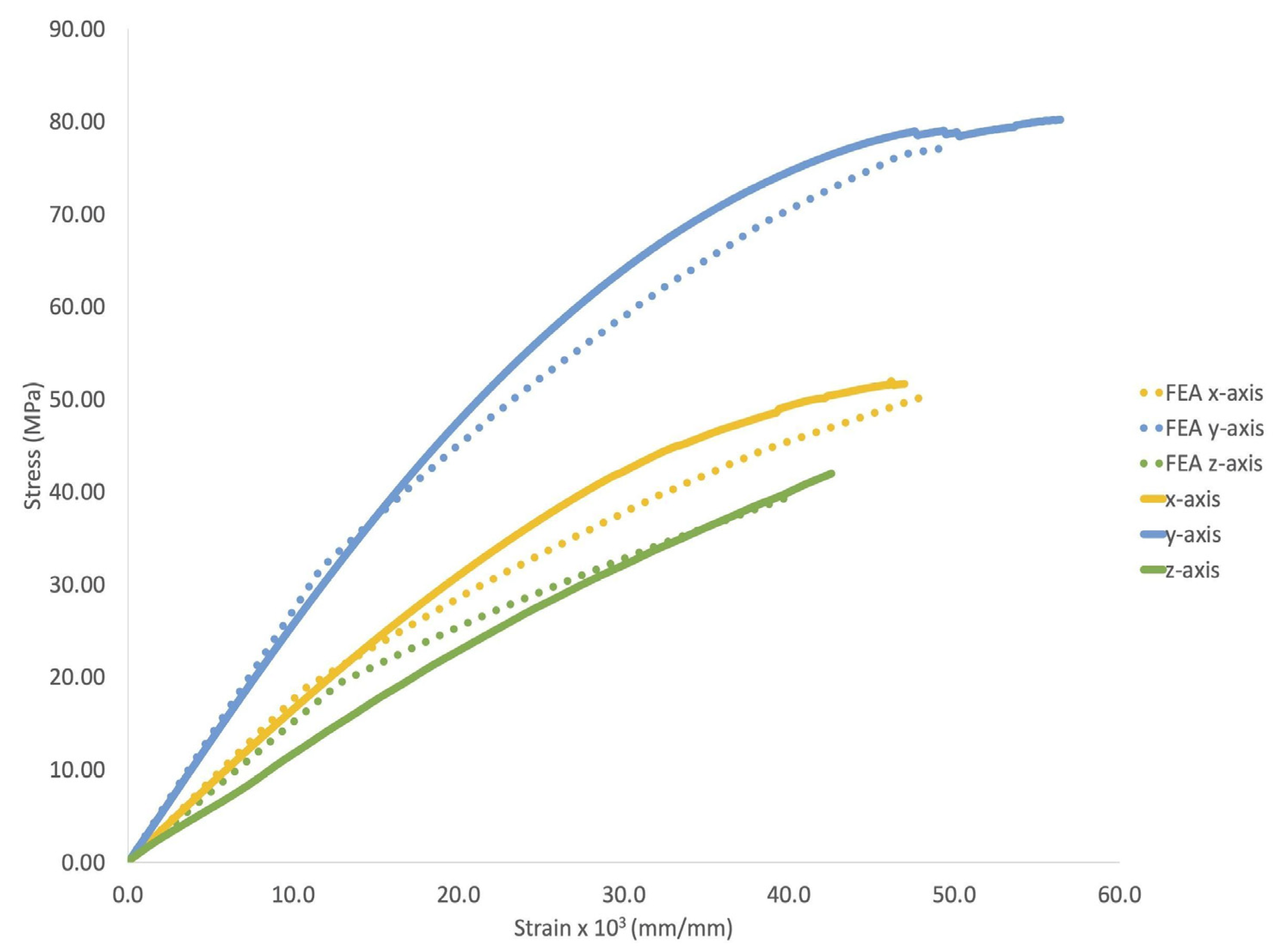
Following the experimental analysis of the solid 3D-printed parts, the stress–strain curves of the printed carbon fiber PEEK material in the x-, y- and z-directions were simulated using the MISO model (see Figure 12). The figure shows that the experimental data compare well (in shape and values) with their corresponding models, where the average differences are 7%, 6% and 13% in x-, y- and z-directions, respectively. Therefore, the ANSYS appointed material (MISO) model and properties were used in the lattice model with confidence. One overarching motivation for this work is to optimize the simulation of mechanical properties of the complex geometries enabled by the sacrificial soluble support material.
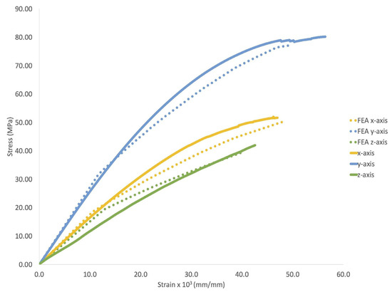
Figure 12.
Experimental and modeled stress–strain curves of the carbon fiber PEEK lattice.
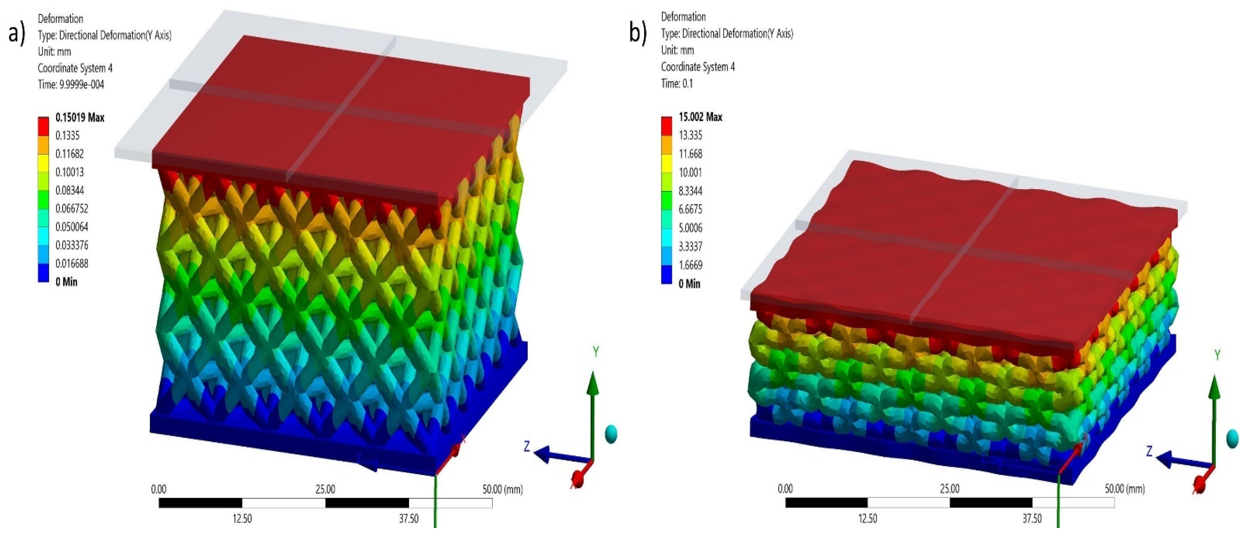
Figure 13 shows the simulated compression profile of the lattice structure. These progressive stress–strain data are plotted in Figure 14 and compared with the experimental data obtained on the compressed carbon fiber PEEK lattice. Although Figure 14 shows numerical results with steeper elastic sections, the plateau and densification sections of the model display both shape and values similar to the experimental results. The absorbed unitary energy calculated at the densification point was 7570 kJ/m3 for the experimental data and 7640 kJ/m3 for the numerical model, which represents a difference of less than 1%. Therefore, the numerical simulation of the lattice represents an accurate model of the experimental results and can be further used to optimize the design and performance of alternative PAEK lattices.

Figure 13.
Simulated sequence of deformation in the y-axis of the lattice specimen: (a) Initial compression and (b) Near full densification.
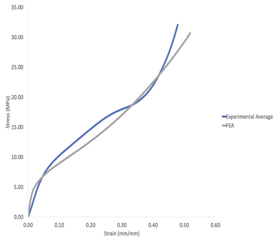
Figure 14.
Numerical versus experimental stress–strain curves of the octahedral carbon fiber PEEK lattice.
4. Conclusions
The compression and flexural tests of 3D-printed amorphous PEEK, semi-crystalline PEEK, carbon fiber PEEK and PEKK lattices based on an octet configuration were performed in this research work. These lattices were manufactured using an extrusion process with the first open-market soluble support material compatible with aromatic ketone structures. The following points have been drawn from the present work:
- A soluble sacrificial support was used to print octet and hexagonal lattices and support compatibility was demonstrated with high-temperature PEEK/PEKK polymers.
- A CT scan analysis showed that printed lattices without support material resulted in overhanging sections with defects. In contrast, the incorporation of sacrificial supporting material resulted in lattice structures without defects and with well-defined dimensional accuracies.
- The carbon fiber PEEK material has shown a distinctive ductile performance. The system did not present signs of fracture under compression even at displacements beyond the densification region. The preliminary impact testing results suggest this material can have potential applications in the field of blast and ballistics.
- The plateau and the densification sections of the numerical results display both shape and values similar to the experimental results with absorbed unitary energy calculated at the densification point of 7570 kJ/m3 for the experimental data and 7640 kJ/m3 for the numerical model, which represents a difference of less than 1%.
- The semi-crystalline PEEK resulted in the highest compressive strength of 21.01 MPa and modulus, a mechanism associated with a higher degree of crystallinity, of 0.361 GPa.
Author Contributions
Conceptualization, C.C.S., B.Y., J.A.D.D.l.P., J.L., K.R., F.T., R.F., K.C., A.D.P., F.S., E.M., P.C.; methodology, C.C.S., B.Y., J.A.D.D.l.P., K.C., A.D.P., F.S., E.M., P.C.; software, C.C.S., B.Y., J.A.D.D.l.P., K.R., A.D.P.; validation, B.Y., P.C.; formal analysis, C.C.S., B.Y., J.A.D.D.l.P., P.C.; investigation, C.C.S., B.Y., J.A.D.D.l.P., A.D.P.; resources, J.L., K.R., F.T., R.F., K.C., E.M., P.C.; data curation, C.C.S., B.Y., J.A.D.D.l.P., A.D.P., P.C.; writing—original draft preparation, C.C.S., B.Y., E.M.D, P.C.; writing—review and editing, B.Y., K.R., F.S., E.M., P.C.; visualization, B.Y., E.M., P.C.; supervision, E.M., P.C.; project administration, B.Y., E.M., P.C.; funding acquisition, E.M., P.C. All authors have read and agreed to the published version of the manuscript.
Funding
This research received no external funding.
Institutional Review Board Statement
Not applicable.
Informed Consent Statement
Not applicable.
Data Availability Statement
The raw/processed data required to reproduce these findings cannot be shared at this time as the data also form part of an ongoing study.
Acknowledgments
We would like to thank the Eynon-Beyer Endowment at Youngstown State University as well as the Murchison Chair at the University of Texas at El Paso.
Conflicts of Interest
The authors declare no conflict of interest. The funders had no role in the design of the study; in the collection, analyses, or interpretation of data; in the writing of the manuscript or in the decision to publish the results.
References
- Haleem, A.; Javaid, M. Polyether Ether Ketone (PEEK) and Its 3D Printed Implants Applications in Medical Field: An Overview. Clin. Epidemiol. Glob. Health 2019, 7, 571–577. [Google Scholar] [CrossRef] [Green Version]
- Garcia-Gonzalez, D.; Rusinek, A.; Jankowiak, T.; Arias, A. Mechanical Impact Behavior of Polyether–ether–ketone (PEEK). Compos. Struct. 2015, 124, 88–99. [Google Scholar] [CrossRef] [Green Version]
- Shekar, R.I.; Kotresh, T.M.; Rao, P.M.D.; Kumar, K. Properties of High Modulus PEEK Yarns for Aerospace Applications. J. Appl. Polym. Sci. 2009, 112, 2497–2510. [Google Scholar] [CrossRef]
- Shekar, R.I.; Damodhara Rao, P.M.; Padaki, V.C.; Kim, N.H.; Lee, J.H. Fibre-Fibre Hybrid Composites for Aerospace Applications. In Proceedings of the Advanced Materials Research; Trans Tech Publications, Ltd.: Bäch, Switzerland, 2010; Volume 123, pp. 1231–1234. [Google Scholar]
- Theiler, G.; Gradt, T. MoS2-Filled PEEK Composite as a Self-Lubricating Material for Aerospace Applications. In Proceedings of the 40th Aerospace Mechanisms Symposium, NASA Kennedy Space Center, Cocoa Beach, FL, USA, 12–14 May 2010. [Google Scholar]
- Denault, J.; Dumouchel, M. Consolidation Process of PEEK/Carbon Composite for Aerospace Applications. Adv. Perform. Mater. 1998, 5, 83–96. [Google Scholar] [CrossRef]
- Roux, M.; Dransfeld, C.; Eguémann, N.; Giger, L. Processing and Recycling of a Thermoplastic Composite Fibre/Peek Aerospace Part. In Proceedings of the 16th European Conference on Composite Materials (ECCM 16), Sevilla, Spain, 22–26 June 2014; pp. 22–26. [Google Scholar]
- Yuan, M.; Galloway, J.A.; Hoffman, R.J.; Bhatt, S. Influence of Molecular Weight on Rheological, Thermal, and Mechanical Properties of PEEK. Polym. Eng. Sci. 2011, 51, 94–102. [Google Scholar] [CrossRef]
- Rinaldi, M.; Cecchini, F.; Pigliaru, L.; Ghidini, T.; Lumaca, F.; Nanni, F. Additive Manufacturing of Polyether Ether Ketone (PEEK) for Space Applications: A Nanosat Polymeric Structure. Polymers 2020, 13, 11. [Google Scholar] [CrossRef] [PubMed]
- Zoidis, P.; Papathanasiou, I.; Polyzois, G. The Use of a Modified Poly-Ether-Ether-Ketone (PEEK) as an Alternative Framework Material for Removable Dental Prostheses. A Clinical Report. J. Prosthodont. 2016, 25, 580–584. [Google Scholar] [CrossRef]
- Vaezi, M.; Yang, S. Extrusion-Based Additive Manufacturing of PEEK for Biomedical Applications. Virtual Phys. Prototyp. 2015, 10, 123–135. [Google Scholar] [CrossRef]
- Panayotov, I.V.; Orti, V.; Cuisinier, F.; Yachouh, J. Polyetheretherketone (PEEK) for Medical Applications. J. Mater. Sci. Mater. Med. 2016, 27, 118. [Google Scholar] [CrossRef]
- Patel, P.; Hull, T.R.; McCabe, R.W.; Flath, D.; Grasmeder, J.; Percy, M. Mechanism of Thermal Decomposition of Poly(ether Ether Ketone) (PEEK) from a Review of Decomposition Studies. Polym. Degrad. Stab. 2010, 95, 709–718. [Google Scholar] [CrossRef] [Green Version]
- Kurtz, S.M.; Devine, J.N. PEEK Biomaterials in Trauma, Orthopedic, and Spinal Implants. Biomaterials 2007, 28, 4845–4869. [Google Scholar] [CrossRef] [Green Version]
- Toth, J.M.; Wang, M.; Estes, B.T.; Scifert, J.L.; Seim, H.B., 3rd; Turner, A.S. Polyetheretherketone as a Biomaterial for Spinal Applications. Biomaterials 2006, 27, 324–334. [Google Scholar] [CrossRef] [Green Version]
- El Halabi, F.; Rodriguez, J.F.; Rebolledo, L.; Hurtós, E.; Doblaré, M. Mechanical Characterization and Numerical Simulation of Polyether-Ether-Ketone (PEEK) Cranial Implants. J. Mech. Behav. Biomed. Mater. 2011, 4, 1819–1832. [Google Scholar] [CrossRef]
- Singh, S.; Prakash, C.; Ramakrishna, S. 3D Printing of Polyether-Ether-Ketone for Biomedical Applications. Eur. Polym. J. 2019, 114, 234–248. [Google Scholar] [CrossRef]
- Haleem, A.; Javaid, M. Polyether Ether Ketone (PEEK) and Its Manufacturing of Customised 3D Printed Dentistry Parts Using Additive Manufacturing. Clin. Epidemiol. Glob. Health 2019, 7, 654–660. [Google Scholar] [CrossRef] [Green Version]
- Lee, W.-T.; Koak, J.-Y.; Lim, Y.-J.; Kim, S.-K.; Kwon, H.-B.; Kim, M.-J. Stress Shielding and Fatigue Limits of Poly-Ether-Ether-Ketone Dental Implants. J. Biomed. Mater. Res. B Appl. Biomater. 2012, 100, 1044–1052. [Google Scholar] [CrossRef] [PubMed]
- Schwitalla, A.; Müller, W.-D. PEEK Dental Implants: A Review of the Literature. J. Oral Implantol. 2013, 39, 743–749. [Google Scholar] [CrossRef] [PubMed]
- Kang, J.; Wang, L.; Yang, C.; Wang, L.; Yi, C.; He, J.; Li, D. Custom Design and Biomechanical Analysis of 3D-Printed PEEK Rib Prostheses. Biomech. Model. Mechanobiol. 2018, 17, 1083–1092. [Google Scholar] [CrossRef] [Green Version]
- Basgul, C.; Yu, T.; MacDonald, D.W.; Siskey, R.; Marcolongo, M.; Kurtz, S.M. Structure-Property Relationships for 3D Printed PEEK Intervertebral Lumbar Cages Produced Using Fused Filament Fabrication. J. Mater. Res. 2018, 33, 2040–2051. [Google Scholar] [CrossRef]
- Liu, D.; Fu, J.; Fan, H.; Li, D.; Dong, E.; Xiao, X.; Wang, L.; Guo, Z. Application of 3D-Printed PEEK Scapula Prosthesis in the Treatment of Scapular Benign Fibrous Histiocytoma: A Case Report. J. Bone Oncol. 2018, 12, 78–82. [Google Scholar] [CrossRef] [PubMed]
- Foletti, J.-M.; Lari, N.; Dumas, P.; Compes, P.; Guyot, L. PEEK customized implant for skull esthetic reconstruction. Rev. Stomatol. Chir. Maxillofac. 2012, 113, 468–471. [Google Scholar] [CrossRef] [PubMed]
- Reber, R. PEKK vs. PEEK: 3D Printing High-Performance Materials. Available online: https://www.aniwaa.com/blog/peek-vs-pekk/ (accessed on 6 April 2020).
- Landry, B.; Hubert, P. Experimental Study of Defect Formation during Processing of Randomly-Oriented Strand carbon/PEEK Composites. Compos. Part A Appl. Sci. Manuf. 2015, 77, 301–309. [Google Scholar] [CrossRef]
- Wu, W.Z.; Geng, P.; Zhao, J.; Zhang, Y.; Rosen, D.W.; Zhang, H.B. Manufacture and Thermal Deformation Analysis of Semicrystalline Polymer Polyether Ether Ketone by 3D Printing. Mater. Res. Innov. 2014, 18, S5-12–S5-16. [Google Scholar] [CrossRef]
- Xiaoyong, S.; Liangcheng, C.; Honglin, M.; Peng, G.; Zhanwei, B.; Cheng, L. Experimental Analysis of High Temperature PEEK Materials on 3D Printing Test. In Proceedings of the 2017 9th International Conference on Measuring Technology and Mechatronics Automation (ICMTMA), Changsha, China, 14–15 January 2017; pp. 13–16. [Google Scholar]
- Schmidt, M.; Pohle, D.; Rechtenwald, T. Selective Laser Sintering of PEEK. CIRP Ann. 2007, 56, 205–208. [Google Scholar] [CrossRef]
- Goodridge, R.D.; Tuck, C.J.; Hague, R.J.M. Laser Sintering of Polyamides and Other Polymers. Prog. Mater Sci. 2012, 57, 229–267. [Google Scholar] [CrossRef]
- Yang, C.; Tian, X.; Li, D.; Cao, Y.; Zhao, F.; Shi, C. Influence of Thermal Processing Conditions in 3D Printing on the Crystallinity and Mechanical Properties of PEEK Material. J. Mater. Process. Technol. 2017, 248, 1–7. [Google Scholar] [CrossRef]
- Wu, W.; Geng, P.; Li, G.; Zhao, D.; Zhang, H.; Zhao, J. Influence of Layer Thickness and Raster Angle on the Mechanical Properties of 3D-Printed PEEK and a Comparative Mechanical Study between PEEK and ABS. Materials 2015, 8, 5834–5846. [Google Scholar] [CrossRef]
- Díez-Pascual, A.M.; Naffakh, M.; González-Domínguez, J.M.; Ansón, A.; Martínez-Rubi, Y.; Martínez, M.T.; Simard, B.; Gómez, M.A. High Performance PEEK/carbon Nanotube Composites Compatibilized with Polysulfones-II. Mechanical and Electrical Properties. Carbon 2010, 48, 3500–3511. [Google Scholar] [CrossRef]
- Hassan, E.A.M.; Ge, D.; Yang, L.; Zhou, J.; Liu, M.; Yu, M.; Zhu, S. Highly Boosting the Interlaminar Shear Strength of CF/PEEK Composites via Introduction of PEKK onto Activated CF. Compos. Part A Appl. Sci. Manuf. 2018, 112, 155–160. [Google Scholar] [CrossRef]
- Love, L.J.; Kunc, V.; Rios, O.; Duty, C.E.; Elliott, A.M.; Post, B.K.; Smith, R.J.; Blue, C.A. The Importance of Carbon Fiber to Polymer Additive Manufacturing. J. Mater. Res. 2014, 29, 1893–1898. [Google Scholar] [CrossRef] [Green Version]
- Tekinalp, H.L.; Kunc, V.; Velez-Garcia, G.M.; Duty, C.E.; Love, L.J.; Naskar, A.K.; Blue, C.A.; Ozcan, S. Highly Oriented Carbon Fiber–polymer Composites via Additive Manufacturing. Compos. Sci. Technol. 2014, 105, 144–150. [Google Scholar]
- Brenken, B.; Barocio, E.; Favaloro, A.; Kunc, V.; Pipes, R.B. Fused Filament Fabrication of Fiber-Reinforced Polymers: A Review. Addit. Manuf. 2018, 21, 1–16. [Google Scholar] [CrossRef]
- Garcia-Leiner, M.; Streifel, B.; Başgül, C.; MacDonald, D.W.; Kurtz, S.M. Characterization of Paek Filaments and Printed Parts Produced by Extrusion-based Additive Manufacturing. Polym. Int. 2021, 70, 128–136. [Google Scholar] [CrossRef]
- Kunc, V.; Kishore, V.; Chen, X.; Ajinjeru, C.; Duty, C.; Hassen, A.A. High Performance Poly (etherketoneketone)(PEKK) Composite Parts Fabricated Using Big Area Additive Manufacturing (BAAM) Processes; Oak Ridge National Lab. (ORNL): Oak Ridge, TN, USA; Manufacturing Demonstration Facility (MDF): Knoxville, TN, USA, 2016.
- Antero 800NA: A PEKK-Based Thermoplastic 3D Printing Material. Available online: https://www.stratasys.com/materials/search/antero-800na (accessed on 9 March 2021).
- Xu, C.; Cheng, K.; Liu, Y.; Wang, R.; Jiang, X.; Dong, X.; Xu, X. Effect of Processing Parameters on Flexural Properties of 3D-printed Polyetherketoneketone Using Fused Deposition Modeling. Polym. Eng. Sci. 2021, 61, 465–476. [Google Scholar] [CrossRef]
- Nachtane, M.; Tarfaoui, M.; Ledoux, Y.; Khammassi, S.; Leneveu, E.; Pelleter, J. Experimental Investigation on the Dynamic Behavior of 3D Printed CF-PEKK Composite under Cyclic Uniaxial Compression. Compos. Struct. 2020, 247, 112474. [Google Scholar] [CrossRef]
- Fischer, S.; Pfister, A.; Galitz, V.; Lyons, B.; Robinson, C.; Rupel, K.; Booth, R.; Kubiak, S. A High Performance Material for Aerospace Applications: Development of Carbon Fiber Filled PEKK for Laser Sintering. In Proceedings of the 26th Annual International Solid Freeform Fabric Symposium, Austin, TX, USA, 10–12 August 2015; pp. 10–12. [Google Scholar]
- Jiang, J.; Xu, X.; Stringer, J. Support Structures for Additive Manufacturing: A Review. J. Mater. Process. Manuf. Sci. 2018, 2, 64. [Google Scholar] [CrossRef] [Green Version]
- Lee, C.-U.; Vandenbrande, J.; Goetz, A.E.; Ganter, M.A.; Storti, D.W.; Boydston, A.J. Room Temperature Extrusion 3D Printing of Polyether Ether Ketone Using a Stimuli-Responsive Binder. Addit. Manuf. 2019, 28, 430–438. [Google Scholar] [CrossRef]
- Pérez-Martín, H.; Mackenzie, P.; Baidak, A.; Brádaigh, C.M.Ó.; Ray, D. Crystallinity Studies of PEKK and Carbon fibre/PEKK Composites: A Review. Compos. Part B 2021, 223, 109127. [Google Scholar] [CrossRef]
- Gurchetan, S.; Ranvijay, K.; Rupinder, S.; Md Mustafizur, R.; Seeram, R. Rheological, Mechanical, Thermal, Tribological and Morphological Properties of PLA-PEKK-HAp-CS Composite. J. Cent. S. Univ. Technol. 2021, 28, 1615–1626. [Google Scholar] [CrossRef]
- du Plessis, A.; le Roux, S.G.; Guelpa, A. The CT Scanner Facility at Stellenbosch University: An Open Access X-Ray Computed Tomography Laboratory. Nucl. Instrum. Methods Phys. Res. B 2016, 384, 42–49. [Google Scholar] [CrossRef] [Green Version]
- Li, T.; Wang, L. Bending Behavior of Sandwich Composite Structures with Tunable 3D-Printed Core Materials. Compos. Struct. 2017, 175, 46–57. [Google Scholar] [CrossRef]
- Al-Ketan, O.; Rowshan, R.; Abu Al-Rub, R.K. Topology-Mechanical Property Relationship of 3D Printed Strut, Skeletal, and Sheet Based Periodic Metallic Cellular Materials. Addit. Manuf. 2018, 19, 167–183. [Google Scholar] [CrossRef]
- Akhmediev, N.N. Model of a Microheterogeneous Elastoplastic Medium Describing the Fatigue Behavior of a Hardening Material at Unsteady Alternating Stress Amplitudes. Strength Mater. 1971, 3, 776–786. [Google Scholar] [CrossRef]
- Robert Basan, T.M. Constitutive Modeling and Material Behavior; University of Rijeka: Rijeka, Croatia, 2016. [Google Scholar]
- Halama, R.; Sedlák, J.; Šofer, M. Phenomenological Modelling of Cyclic Plasticity. In Numerical Modelling; Miidla, P., Ed.; IntechOpen: Rijeka, Croatia, 2012. [Google Scholar]
- Benedetti, L.; Brulé, B.; Decraemer, N.; Davies, R.; Evans, K.E.; Ghita, O. A Route to Improving Elongation of High-Temperature Laser Sintered PEKK. Addit. Manuf. 2020, 36, 101540. [Google Scholar] [CrossRef]
- Wang, X.; Jiang, M.; Zhou, Z.; Gou, J.; Hui, D. 3D Printing of Polymer Matrix Composites: A Review and Prospective. Compos. Part B 2017, 110, 442–458. [Google Scholar] [CrossRef]
- Chacón, J.M.; Caminero, M.Á.; García-Plaza, E.; Nuñez López, P.J. Additive Manufacturing of PLA Structures Using Fused Deposition Modelling: Effect of Process Parameters on Mechanical Properties and Their Optimal Selection. Mater. Des. 2017, 124, 143–157. [Google Scholar] [CrossRef]


Publisher’s Note: MDPI stays neutral with regard to jurisdictional claims in published maps and institutional affiliations. |
© 2021 by the authors. Licensee MDPI, Basel, Switzerland. This article is an open access article distributed under the terms and conditions of the Creative Commons Attribution (CC BY) license (https://creativecommons.org/licenses/by/4.0/).