Abstract
Graphene is a good candidate for protective material owing to its extremely high stiffness and high strength-to-weight ratio. However, the impact performance of twisted bilayer graphene is still obscure. Herein we have investigated the ballistic resistance capacity of twisted bilayer graphene compared to that of AA-stacked bilayer graphene using molecular dynamic simulations. The energy propagation processes are identical, while the ballistic resistance capacity of the twisted bilayer graphene is almost two times larger than the AA-bilayer graphene. The enhanced capacity of the twisted bilayer graphene is assumed to be caused by the mismatch between the two sheets of graphene, which results in earlier fracture of the first graphene layer and reduces the possibility of penetration.
1. Introduction
Materials for ballistic protection have been an important research topic throughout human history [1,2,3,4,5,6]. In order to stop high-speed projectiles, the material should be able to absorb large amounts of kinetic energy. Most current body armor is mostly made of lightweight fibrous materials exhibiting high stiffness and a high strength-to-weight ratio [2]. The fibrous materials can disperse the impact energy rapidly to the area far from the impact center through conic deformation and elastic wave. Considering that graphene is lightweight and has extremely high stiffness and strength [7,8,9,10,11,12,13,14,15], it seems to be a natural protective material.
Recently, Lee et al. demonstrated experimentally that the specific penetration energy of multilayer graphene is around 10 times larger than literature values for macroscopic steel sheets, which means graphene can be an extraordinary candidate of armor material [16,17,18,19]. The reason is attributed to the excellent impact–energy-delocalization property of graphene arising from its superior in-plane speed of sound, high strength, stiffness, and structural anisotropy [17].
Bilayer graphene (BLG) also illustrates advanced physical properties [20,21,22,23,24,25,26]. When the two sheets of bilayer graphene are twisted relative to each other by a certain angle, which forms the called twisted bilayer graphene (tBLG) [27,28,29], the intrinsic strength along transverse direction can be apparently increased with a slight change in the in-plane properties [30]. Consequently, tBLG may be harder to be penetrated than bilayer graphene without losing the superiority in the energy-delocalization property. This indicates that the tBLG should be able to absorb more energy during impact and thus possesses better ballistic resistance capacity [31].
A few efforts have addressed the ballistic properties of graphene membranes. Haque et al. analyzed the penetrating impact of 1–3 layers of graphene by molecular dynamics (MD) simulations [32]. Similar petal-shaped crack orifices were observed in the LIPIT. Meguid et al. is concerned with the ballistic behavior of multilayer graphene polymer composite [33]. They revealed that the ballistic impact resistance of polyethylene by over eight-fold with a single graphene layer membrane. Azevedo et al. analyzed the ballistic performance of a carbon-based material named penta-graphene [34]. Their results show that the fracture pattern is more spherical. Zhang et al. developed the transverse impact responses of three kinds of bilayers (h-BN/h-BN, graphene/graphene, and hybrid graphene/h-BN) twisted by molecular dynamics simulations [35]. Despite these efforts, the ballistic resistance performance of twisted bilayer graphene is still not fully understood. Motivated by the outstanding electronic properties of twisted bilayer graphene, we aim to study their impact resistance behaviors. By means of molecular dynamics simulations, we found that tBLG with a certain twist angle is a better ballistic protection material than BLG. The responses of tBLG and the referenced BLG under transverse impact loading and the mechanism for the enhanced capacity are investigated using molecular dynamic simulations [36].
2. Methods
2.1. Model and Molecular Dynamics Simulations
Molecular dynamics simulations were conducted using the large-scale atomic/molecular massively parallel simulator (LAMMPS) [37]. Through time and ensemble average of motion trajectory, the dynamic properties of the system are obtained. It can model extensive systems using a variety of interatomic potentials and boundary conditions [38,39]. A unit cell of tBLG was prepared according to Uchida’s method [40]. Then it was further extended to a scale of around 80 nm to avoid the influence of the reflected elastic waves. The projectile was a diamond ball with a radius r = 3.57 nm. A periodic boundary condition was applied to the in-plane (x and y) directions, and the out-of-plane directions (z) were fixed at 6 nm. All simulations of impacts were conducted under micro-canonical (NVE) ensemble to maintain energy conservation in the entire system. Before the simulation, the system was fully relaxed in an isothermal-isobaric ensemble (NPT) for 40 ps at a temperature of 300 K and pressure of 1 atmosphere for both atomistic positions and simulation box dimensions in the in-plane directions to minimize the residue stresses. The time-step was set at 0.001 ps. For both BLG and tBLG samples, the same impacting processed were simulated twenty times, respectively, with different relaxation times.
The interaction of C–C bonds in a diamond ball and graphene layers is described by the second-generation reactive empirical bond order (REBO) potential, which can precisely describe the in-plane elastic properties of graphene and diamond [41,42,43]. The Lennard–Jones (LJ) potential was used for the rest of the van der Waals interactions, with parameters of 0.023049 eV and 2.852 Å for the interaction between diamond and graphene and 0.00284 eV and 3.4 Å for that between the two graphene layers [44]. This is a widely used potential for describing the interaction between two graphene layers [44]. Then the projectile was fired toward the center of samples transversely with an initial speed of 2.2 km/s. The simulation temperature was maintained at 300 K using a Nose–Hoover thermostat [45]. Other parameters were set the same for all the simulations. The penetration analyses were performed using OVITO [46].
2.2. Calculation of Perimeter of Crack Orifice
Common damage caused by a pass-through projectile during an impact test was an irregular left-over crack orifice. We introduced the quantity of perimeter of such an orifice as a descriptor of the damage caused by the applied projectile. We assumed the perimeter of one single atom was 1 (as a unit). For graphene lattice, there were three nearest atoms for each atom. Whenever an atom lost the nearest atom because of fracture or other reasons, it contributed 1/3 to the perimeter. The atoms with three nearest neighbor atoms contributed zero to the perimeter. First, we counted the nearest atoms for each atom within the impact center. Then we added up their corresponding contributions to the perimeter to had the quantity.
3. Results and Discussion
3.1. Atomistic Structures
The atomic configurations of AA-stacked bilayer graphene and twisted bilayer graphene tBLG in a unit cell are illustrated in Figure 1a,b, respectively, after full relaxation. Our results suggest that AA-stacked bilayer graphene is thermodynamically stable in our NPT ensemble at 300 K and 1 atmosphere pressure under the applied boundary conditions.
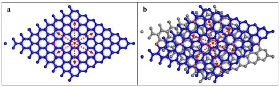
Figure 1.
(a) Atomic configuration of bilayer graphene (BLG). (b) Atomic configuration of twisted bilayer graphene (tBLG) with a twist angle of 21.79°. The atoms marked red are those that overlap with the atoms in the second graphene layer.
3.2. Angle Effect on the Impact
We examined the angle effect on the impact performance of twisted bilayer graphene. The impact processes were simulated on the samples with 9 different twist angles including 0.0°, 3.89°, 7.34°, 9.43°, 13.17°, 18.73°, 21.79°, 25.04° and 30.0°. The bullet was simulated by a diamond ball with a radius of 3.57 nm. We invested the impact using several impact speeds. The ballistic limit fell between 2.0 km/s and 2.5 km/s, so the initial velocities of the bullet were chosen within this range.
When the bullet velocity was 2.0 km/s, none of the samples were penetrated. When it came to 2.2 km/s, the tBLG samples with a twist angle of 7.34°, 18.73°, 21.79° and 25.04° were able to stop the bullet. However, the BLG (= 0.0°) and other tBLG samples (= 3.89°,9.43°, 13.17°, and 30.0°) failed to stop the bullet. When the bullet velocity reached 2.5 km/s, all of the samples were penetrated.
3.3. Penetration Comparison
To investigate the different performance on the ballistic resistance between BLG and tBLG, the bullet velocity of 2.2 km/s was fixed in all the following simulations. Among those non-penetrated samples in the bullet velocity of 2.2 km/s, tBLG with a twist angle 21.79° was selected to compare with the referenced BLG. A movie of the impacting process can be seen in the supplementary information.
After the ball impacted on the sample, an elastic wave radially propagated at high-speed, and a conic deformation (cone wave) followed afterward in good agreement with the experiment and previous simulation results for graphene [17,19]. To eliminate accidental errors caused by certain configurations of atoms, the simulations of impacting processed for BLG and tBLG were repeated twenty times, respectively. In each repeated simulation, the system was equilibrated with a different number of time-steps to obtain a different atomic configuration with a slight change in the position and velocity. Statistically, the ballistic resistance capacity of tBLG was 187.5% better than the referenced BLG—the possibility for the resistance of penetration was 40% for BLG and was 75% for tBLG.
According to the penetration situation, all the simulations were classified into four cases for further comparison, namely penetrated cases for BLG, non-penetrated cases for BLG, penetrated cases for tBLG and non-penetrated cases for tBLG. In all the cases, the first graphene layer was fractured. Setting the time zero point as when the bullet was 10 Å away from the first graphene layer, the average fracture of the first graphene layer started at 2.08 ps for tBLG and 2.39 ps for BLG, showing little difference between penetrated and non-penetrated cases. It appeared that the first graphene layer of tBLG could actually provide less protection to the second layer than BLG. Correspondingly, in these penetrated cases, the average fracture of the second graphene layer in tBLG started earlier than BLG, which was 3.28 ps for tBLG and 3.51 ps for BLG. However, this seemed contradictory with the earlier fracture of the first graphene layer and the lower penetration probability for tBLG, which needs further investigation.
3.4. Energy Propagation Process
The advantage of graphene serving as armor material is its excellent performance in energy delocalization [17,19]. Therefore, we were particularly interested in the energy propagation process in tBLG and BLG. Figure 2a is the energy absorbed by the first graphene layer in both penetrated and non-penetrated cases for BLG and tBLG, respectively. In the end, the first graphene layer in tBLG absorbed less energy, owing to its earlier fracture. However, there was little difference between BLG and tBLG before the fracture of the first graphene layer as well as between the penetrated and non-penetrated cases. It seemed strange that the tBLG performed worse in terms of energy absorption yet possessed a lower penetration probability. Figure 2b is the energy and out-of-plane displacement profile of the second graphene layer at t = 3.0 ps. The profile is illustrated along the line that goes through the impact center parallel to the armchair direction of the second graphene layer. The comparison of the energy curves and displacement curves in Figure 2b indicates that the energy was mostly transferred through a cone wave rather than an elastic wave. The propagation speeds of cone wave, which also represents the dissipation speeds of energy along a longitudinal direction, for BLG and tBLG, in both penetrated and non-penetrated cases, were nearly identical. The energy profile along the zigzag direction can be seen in Figure S2 in the supplementary material. Moreover, the phonon density of state also showed a significant similarity between BLG and tBLG, which means an equivalent energy dissipation speed in terms of atomic vibration between BLG and tBLG. Above all, tBLG showed neither advantage nor a disadvantage in energy delocalization. Namely, by twisting a certain angle between two sheets of graphene, it did not lose its superiority in the energy-delocalization property.
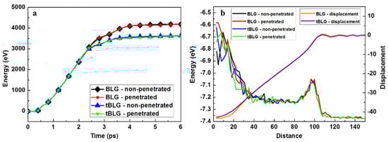
Figure 2.
Energy propagation in different samples. (a) Energy is absorbed by the first graphene layer of BLG and tBLG samples during the impact process. (b) The profile of energy and out-of-plane displacement along the armchair direction of the second graphene layer for BLG and tBLG samples at t = 3.0 ps.
3.5. Crack Orifice Patterns
In order to get insight into the fracture mechanism, the evolution of the crack-orifice patterns during the impact process is demonstrated in Figure 3. Normally three to six cracks were initiated near the impact center and propagate outwards along the zigzag direction of graphene layers, creating the same number of triangular-shaped petals. The damaged area spread quickly and finally became much larger than the impact area (outlined in dashed line in Figure 3). Such behavior agrees well with the experimental results [17].
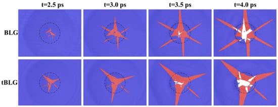
Figure 3.
Crack-orifice patterns of BLG and tBLG evolving with time in penetrated cases. The dashed circle outlines the diamond projectile impact region. The top (first) graphene layer carbon atoms are blue. The bottom (second) graphene layer carbon atoms are red. The white color represents the broken region where both top and bottom layers of graphene are removed so that there are no carbon atoms. Some small, isolated objects are debris of carbon atoms of the top (blue) or bottom (red) graphene layer.
Due to the high-speed impact of the bullet, three to six cracks were initiated near the impact center. The huge kinetic energy destroyed the graphene bond in the center of the impact, then due to the damaged area spread quickly, some atoms near the edge of petals were divorced from the petals, forming some fragments in the damaged area. Those fragments trapped in the impact region owing to the high velocity of the bullet were further pushed by the bullet and result in high-stress concentration points in the second layer, as shown in Figure S4a. It should be noticed that the cracks in the second layer always initiated from the position where some fragments of the fractured first layer existed. The crack-orifice patterns of all the cases simulated in this work are presented in Figure S4b.
3.6. Chaos Degree
In penetrated cases, there were more fragments trapped in the impact region on the first layer than those in non-penetrated cases. The fragments were assumed to play an important role in the fracture of the second layer. Here we use the term “chaos degree”, defined as the total in-plane perimeter of atoms within the impact region (See Methods section), to evaluate the influence of fragments.
Considering that both cracks and fragments can be expressed by the in-plane perimeter of atoms, chaos degree could be helpful to explore the failure mechanism. The results are shown in Figure 4, and the data in each time point were averaged over all the simulations that belong to the same case. The dramatic increase of the chaos degree at around 2 ps was caused by the fracture of the first layer. The subsequent decrease was caused by the petals and fragments moving out from the impact region. Because of the earlier fracture of the first layer, the increase and decrease of the chaos degree for tBLG were both earlier than that for BLG.
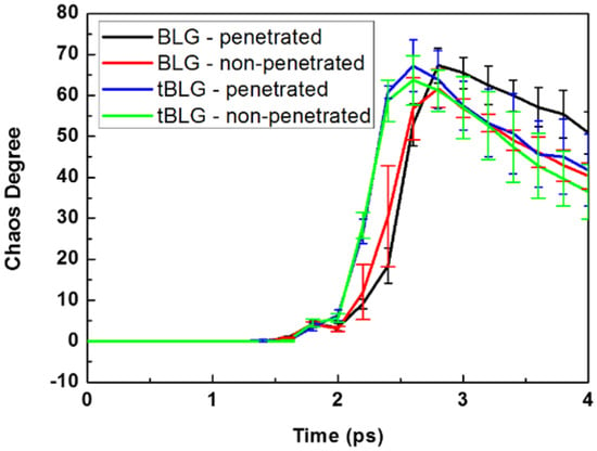
Figure 4.
The chaos degree of atoms within the impact region in each case evolving with time.
For both tBLG and BLG, the peak chaos degree in penetrated cases was larger than in non-penetrated cases. This means that the penetration of the second layer was relevant to the worse chaos degree. The decreasing speed of chaos degree showed a slight difference between penetrated and non-penetrated cases for tBLG. Whereas for BLG, the decreasing speed of chaos degree in penetrated cases was much slower than that in non-penetrated cases. This indicated that the slower escape speed of fragments and petals in BLG was one of the reasons for the fracture of the second layer.
3.7. Kinetic Energy Dissipation
The total kinetic energy of atoms within the impact region is shown in Figure 5. The data were averaged over all the simulations that belong to the same case. All the curves exhibited two main peaks. Before the first peak, the atoms were sped up by the bullet consecutively until they reach the same speed as the bullet. Then the atoms started to slow down owing to the reduction of the speed of the bullet. When the first graphene layer fractured, the stored strain energy was released and transformed into the kinetic energy of the petals and fragments, resulting in the formation of the second peak in the curves.
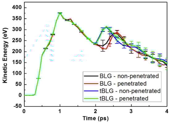
Figure 5.
The total kinetic energy of atoms within the impact region in each case evolving with time.
Owing to the earlier fracture of the first layer, the fragments of tBLG had slightly larger kinetic energy than that of BLG. As a result, the fragments of tBLG possessed higher mobility and were more likely to move out from the impact region, making tBLG less likely to be penetrated. Above all, the lower probability of tBLG to create fragments with high chaos degree in the impact region and the higher mobility of the fragments should be responsible for the enhanced capacity of tBLG.
The earlier fracture of the first layer was assumed to be caused by the mismatch between two sheets of graphene. During the transverse impact, the distance between two layers of graphene was reduced greatly, leading to intensive interaction between atoms in two layers. Because of the perfect overlap of the two layers of graphene and the symmetry of lattice for BLG, each atom on the first layer suffered identical force generated by atoms in the second layer. All the forces were perpendicular to the graphene plane. For tBLG, the symmetry was broken down. The forces generated by the second layer were different for each atom in the first layer and no longer perpendicular to the graphene plane, whose component force in the plane helped to break the bonds between atoms and caused the earlier fracture of the first layer.
Besides the symmetry, the mismatch of lattice also resulted in a decrease in the crack number, which may have reduced the formation of fragments. As shown in Figure 3 and Figure S4, in most cases, six main cracks formed in the first graphene layer in BLG, but only three to four in tBLG. The cracks always propagated along the six zigzag directions, as illustrated by the red arrows in Figure 1. For tBLG, when cracks in the first layer propagated along different zigzag directions, the atoms near the cracks suffered different resistance forces generated from the second graphene layer. Therefore, the cracks propagated preferentially along certain zigzag directions and resulted in a decrease in the crack number.
4. Conclusions
We assessed the ballistic impact resistance performance of twisted bilayer graphene using molecular dynamics simulations under various conditions. We revealed that the second layer of twisted bilayer graphene with the twist angle of 21.79° was harder to penetrate than the second layer of the referenced bilayer graphene by simulating their responses under the high-speed transverse impact, which was selected to always penetrate the first layer. It was observed that the penetration of the second layer was related to the fragments of the first layer within the impact region. The fragments in the twisted bilayer graphene were less likely to be trapped in the impact region due to their higher mobility resulting from the earlier fracture of the first layer than in the referenced bilayer graphene. The statistical analysis showed that the ballistic resistance capacity of the twisted bilayer graphene was almost double that of AA bilayer graphene. Our atomistic results and insights may be helpful in the design of graphene-based armor materials.
Supplementary Materials
The following are available online at https://www.mdpi.com/2073-4352/11/2/206/s1, Figure S1: Configurations and monitor points, Figure S2: Energy propagation process along the x-direction of tBLG samples, Figure S3: Energy propagation process at 2 km/s, Figure S4: Stress distribution of lower graphene layer for tBLGs with different twist angle, Figure S5: Stress in the x-y plane versus time relationship. Movie S1: Kinetics of the impact on tBLG with a twist-angle of 0°; Movie S2: Kinetics of the impact on tBLG with a twist-angle of 3.89°; Movie S3: Kinetics of the impact on tBLG with a twist-angle of 7.34°; Movie S4: Kinetics of the impact on tBLG with a twist-angle of 21.79°; Movie S5: Kinetics of the impact on tBLG with a twist-angle of 30.0°.
Author Contributions
Q.P. and Q.C. conceived the idea of the paper; Q.P. and Q.C. designed and performed the simulations and wrote the original draft; S.P. and Q.P. discussed the results and modified the manuscript. All authors have read and agreed to the published version of the manuscript.
Funding
The National Natural Science Foundation of China: 51727901; The Strategic Priority Research Program of the Chinese Academy of Sciences: XDA25040102; the Deanship of Scientific Research (DSR) at King Fahd University of Petroleum & Minerals (KFUPM): SR191013.
Acknowledgments
Q.C. would like to acknowledge the Strategic Priority Research Program of the Chinese Academy of Sciences (Grant No. XDA25040102), the National Natural Science Foundation of China (Grant No. 51727901). Q.P. would like to acknowledge the support provided by the Deanship of Scientific Research (DSR) at King Fahd University of Petroleum and Minerals (KFUPM) for funding this work through project No. SR191013. For computer time, this research used the resources of the Supercomputing Laboratory at King Abdullah University of Science Technology (KAUST) in Thuwal, Saudi Arabia.
Conflicts of Interest
The authors declare no conflict of interest.
References
- Lee, S.W.R.; Sun, C.T. Dynamic penetration of graphite/epoxy laminates impacted by a blunt-ended projectile. Compos. Sci. Technol. 1993, 49, 369–380. [Google Scholar] [CrossRef]
- Leigh Phoenix, S.; Porwal, P.K. A new membrane model for the ballistic impact response and V50 performance of mul-ti-ply fibrous systems. Int. J. Solids Struct. 2003, 40, 6723–6765. [Google Scholar] [CrossRef]
- Fatt, M.S.H.; Lin, C.; Revilock, D.M., Jr.; Hopkins, D.A. Ballistic impact of GLARETM fiber–metal laminates. Compos. Struct. 2003, 61, 73–88. [Google Scholar] [CrossRef]
- Cheeseman, B.A.; Bogetti, T.A. Ballistic impact into fabric and compliant composite laminates. Compos. Struct. 2003, 61, 161–173. [Google Scholar] [CrossRef]
- Tabiei, A.; Nilakantan, G. Ballistic Impact of Dry Woven Fabric Composites: A Review. Appl. Mech. Rev. 2008, 61, 010801. [Google Scholar] [CrossRef]
- Mylvaganam, K.; Zhang, L.C. Ballistic resistance capacity of carbon nanotubes. Nanotechnology 2007, 18, 475701. [Google Scholar] [CrossRef]
- Cao, Q.; Geng, X.; Wang, H.; Wang, P.; Liu, A.; Lan, Y.; Peng, Q. A Review of Current Development of Graphene Mechanics. Crystals 2018, 8, 357. [Google Scholar] [CrossRef]
- Peng, Q.; Crean, J.; Han, L.; Liu, S.; Wen, X.; De, S.; Dearden, A.K. New materials graphyne, graphdiyne, graphone, and graphane: Review of properties, synthesis, and application in nanotechnology. Nanotechnol. Sci. Appl. 2014, 7, 1–29. [Google Scholar] [CrossRef] [PubMed]
- Li, Y. Twist-enhanced stretchability of graphene nanoribbons: A molecular dynamics study. J. Phys. D Appl. Phys. 2010, 43, 495405. [Google Scholar] [CrossRef]
- Chen, M.; Muniz, A.R.; Maroudas, D. Formation and Mechanical Behavior of Nanocomposite Superstructures from Interlayer Bonding in Twisted Bilayer Graphene. ACS Appl. Mater. Interfaces 2018, 10, 28898–28908. [Google Scholar] [CrossRef] [PubMed]
- Peng, Q.; Chen, Z.; De, S. A Density Functional Theory Study of the Mechanical Properties of Graphane with van der Waals Corrections. Mech. Adv. Mater. Struct. 2012, 22, 717–721. [Google Scholar] [CrossRef]
- Peng, Q.; Ji, W.; De, S. Mechanical properties of graphyne monolayers: A first-principles study. Phys. Chem. Chem. Phys. 2012, 14, 13385–13391. [Google Scholar] [CrossRef]
- Xu, J.; Yuan, G.; Zhu, Q.; Wang, J.; Tang, S.; Gao, L. Enhancing the Strength of Graphene by a Denser Grain Boundary. ACS Nano 2018, 12, 4529–4535. [Google Scholar] [CrossRef]
- Wang, P.; Cao, Q.; Yan, Y.; Nie, Y.; Liu, S.; Peng, Q. Graphene Surface Reinforcement of Iron. Nanomaterials 2019, 9, 59. [Google Scholar] [CrossRef]
- Peng, Q.; Chen, X.-J.; Ji, W.; De, S. Chemically Tuning Mechanics of Graphene by BN. Adv. Eng. Mater. 2013, 15, 718–727. [Google Scholar] [CrossRef]
- Murr, L.; Quinones, S.A.; Ayala, A.; Valerio, O.L.; Hörz, F.; Bernhard, R. The low-velocity-to-hypervelocity penetration transition for impact craters in metal targets. Mater. Sci. Eng. 1998, 256, 166–182. [Google Scholar] [CrossRef]
- Lee, J.-H.; Loya, P.E.; Lou, J.; Thomas, E.L. Dynamic mechanical behavior of multilayer graphene via supersonic projectile penetration. Science 2014, 346, 1092–1096. [Google Scholar] [CrossRef]
- Bizao, R.A.; Machado, L.D.; Sousa, J.M.; De Pugno, N.M.; Galvao, D.S. Scale effects on the ballistic penetration of gra-phene sheets. Sci. Rep. 2018, 8, 1–8. [Google Scholar] [CrossRef] [PubMed]
- Haque, B.Z.; Chowdhury, S.C.; Gillespie, J.W. Molecular simulations of stress wave propagation and perforation of graphene sheets under transverse impact. Carbon 2016, 102, 126–140. [Google Scholar] [CrossRef]
- Stepanov, P.; Das, I.; Lu, X.; Fahimniya, A.; Watanabe, K.; Taniguchi, T.; Koppens, F.H.L.; Lischner, J.; Levitov, L.; Efetov, D.K. Untying the insulating and superconducting orders in magic-angle graphene. Nat. Cell Biol. 2020, 583, 375–378. [Google Scholar] [CrossRef]
- Marchenko, D.; Evtushinsky, D.V.; Golias, E.; Varykhalov, A.; Seyller, T.; Rader, O. Extremely flat band in bilayer graphene. Sci. Adv. 2018, 4, eaau0059. [Google Scholar] [CrossRef]
- Cao, Y.; Fatemi, V.; Fang, S.; Watanabe, K.; Taniguchi, T.; Kaxiras, E.; Jarillo-Herrero, P. Unconventional superconductivity in magic-angle graphene superlattices. Nat. Cell Biol. 2018, 556, 43–50. [Google Scholar] [CrossRef] [PubMed]
- Cao, Y.; Fatemi, V.; Demir, A.; Fang, S.; Tomarken, S.L.; Luo, J.Y.; Sanchez-Yamagishi, J.D.; Watanabe, K.; Taniguchi, T.; Kaxiras, E.; et al. Correlated insulator behaviour at half-filling in magic-angle graphene superlattices. Nat. Cell Biol. 2018, 556, 80–84. [Google Scholar] [CrossRef] [PubMed]
- Ju, L.; Wang, L.; Cao, T.; Taniguchi, T.; Watanabe, K.; Louie, S.G.; Rana, F.; Park, J.; Hone, J.; Wang, F.; et al. Tunable excitons in bilayer graphene. Science 2017, 358, 907–910. [Google Scholar] [CrossRef] [PubMed]
- Li, J.I.A.; Tan, C.; Chen, S.; Zeng, Y.; Taniguchi, T.; Watanabe, K.; Hone, J.; Dean, C.R. Even-denominator fractional quantum Hall states in bilayer graphene. Science 2017, 358, 648–652. [Google Scholar] [CrossRef] [PubMed]
- Mayorov, A.S.; Elias, D.C.; Mucha-Kruczynski, M.; Gorbachev, R.V.; Tudorovskiy, T.; Zhukov, A.; Morozov, S.V.; Katsnelson, M.I.; Geim, A.K.; Novoselov, K.S.; et al. Interaction-Driven Spectrum Reconstruction in Bilayer Graphene. Science 2011, 333, 860–863. [Google Scholar] [CrossRef]
- Arora, H.S.; Polski, R.; Zhang, Y.; Thomson, A.; Choi, Y.; Kim, H.; Lin, Z.; Wilson, I.Z.; Xu, X.; Chu, J.-H.; et al. Superconductivity in metallic twisted bilayer graphene stabilized by WSe2. Nat. Cell Biol. 2020, 583, 379–384. [Google Scholar] [CrossRef]
- Sharpe, A.L.; Fox, E.J.; Barnard, A.W.; Finney, J.; Watanabe, K.; Taniguchi, T.; Kastner, M.A.; Goldhaber-Gordon, D. Emergent ferromagnetism near three-quarters filling in twisted bilayer graphene. Science 2019, 365, 605–608. [Google Scholar] [CrossRef]
- Yankowitz, M.; Chen, S.; Polshyn, H.; Zhang, Y.; Watanabe, K.; Taniguchi, T.; Graf, D.; Young, A.F.; Dean, C.R. Tuning superconductivity in twisted bilayer graphene. Science 2019, 363, 1059–1064. [Google Scholar] [CrossRef]
- Zheng, S.; Cao, Q.; Liu, S.; Peng, Q. Atomic Structure and Mechanical Properties of Twisted Bilayer Graphene. J. Compos. Sci. 2018, 3, 2. [Google Scholar] [CrossRef]
- Yang, Y.; Cao, Q.; Gao, Y.; Lei, S.; Liu, S.; Peng, Q. High impact resistance in graphyne. RSC Adv. 2020, 10, 1697–1703. [Google Scholar] [CrossRef]
- Qiu, Y.; Zhang, Y.; Ademiloye, A.S.; Wu, Z. Molecular dynamics simulations of single-layer and rotated double-layer graphene sheets under a high velocity impact by fullerene. Comput. Mater. Sci. 2020, 182, 109798. [Google Scholar] [CrossRef]
- Dewapriya, M.; Meguid, S. Comprehensive molecular dynamics studies of the ballistic resistance of multilayer graphene-polymer composite. Comput. Mater. Sci. 2019, 170, 109171. [Google Scholar] [CrossRef]
- Azevedo, D.L.; Bizao, R.A.; Galvao, D.S. Molecular dynamics simulations of ballistic penetration of penta-graphene sheets. MRS Adv. 2018, 3, 433–437. [Google Scholar] [CrossRef]
- Yang, X.; Zhang, B. Twisted bilayer graphene/h-BN under impact of a nano-projectile. Appl. Surf. Sci. 2021, 538, 148030. [Google Scholar] [CrossRef]
- Peng, Q.; Meng, F.; Yang, Y.; Lu, C.; Deng, H.; Wang, L.; De, S.; Gao, F. Shockwave generates dislocation loops in bcc iron. Nat. Commun. 2018, 9, 1–6. [Google Scholar] [CrossRef]
- Plimpton, S. Fast Parallel Algorithms for Short-Range Molecular Dynamics. J. Comput. Phys. 1995, 117, 1–19. [Google Scholar] [CrossRef]
- Peng, Q.; Deng, B.; Utz, M. Reduced Plastic Dilatancy in Polymer Glasses. Macromol. Theory Simul. 2021. [Google Scholar] [CrossRef]
- Alder, B.J.; Wainwright, T.E. Phase Transition for a Hardsphere System. J. Chem. Phys. 1957, 27, 5. [Google Scholar] [CrossRef]
- Uchida, K.; Furuya, S.; Iwata, J.-I.; Oshiyama, A. Atomic corrugation and electron localization due to Moiré patterns in twisted bilayer graphenes. Phys. Rev. B 2014, 90, 1–9. [Google Scholar] [CrossRef]
- Brenner, D.W.; Shenderova, O.A.; Harrison, J.A.; Stuart, S.J.; Ni, B.; Sinnott, S.B. A second-generation reactive empirical bond order (REBO) potential energy expression for hydrocar-bons. Mater. Sci. 2002, 14, 783–802. [Google Scholar]
- Hou, J.; Deng, B.; Zhu, H.; Lan, Y.; Shi, Y.; De, S.; Liu, L.; Chakraborty, P.; Gao, F.; Peng, Q. Magic auxeticity angle of graphene. Carbon 2019, 149, 350–354. [Google Scholar] [CrossRef]
- Deng, B.; Hou, J.; Zhu, H.; Liu, S.; Liu, E.; Shi, Y.; Peng, Q. The normal-auxeticity mechanical phase transition in graphene. 2D Mater. 2017, 4, 021020. [Google Scholar] [CrossRef]
- Neek-Amal, M.; Peeters, F.M. Nanoindentation of a circular sheet of bilayer graphene. Phys. Rev. B 2010, 81, 235421. [Google Scholar] [CrossRef]
- Hoover, W.G. Canonical dynamics: Equilibrium phase-space distributions. Phys. Rev. A 1985, 31, 1695–1697. [Google Scholar] [CrossRef]
- Stukowski, A. Visualization and analysis of atomistic simulation data with OVITO—The Open Visualization Tool. Model. Simul. Mater. Sci. Eng. 2009, 18, 15012. [Google Scholar] [CrossRef]


Publisher’s Note: MDPI stays neutral with regard to jurisdictional claims in published maps and institutional affiliations. |
© 2021 by the authors. Licensee MDPI, Basel, Switzerland. This article is an open access article distributed under the terms and conditions of the Creative Commons Attribution (CC BY) license (http://creativecommons.org/licenses/by/4.0/).