Article

Influence of Gas Density and Plug Diameter on Plume Characteristics by Ladle Stirring

1
Institute of Iron and Steel Technology, Technical University Bergakademie Freiberg, Leipziger Straße 34, 09599 Freiberg, Germany
2
Faculty of Metals Engineering and Industrial Computer Science, AGH University of Science and Technology in Kraków, Av. A. Mickiewicza 30, 30-059 Krakow, Poland
*
Author to whom correspondence should be addressed.
Crystals 2021, 11(5), 475; https://doi.org/10.3390/cryst11050475
Submission received: 18 January 2021 / Revised: 20 April 2021 / Accepted: 22 April 2021 / Published: 23 April 2021
(This article belongs to the Special Issue Liquid Steel Alloying Process)

Abstract

:
The paper presents new results concerning the influence of the gas density and porous plug diameter on the nature of liquid steel stirring with an inert gas in the ladle. The tests were carried out on a cold model of a 30t ladle using particle image velocimetry (PIV) with a high-speed camera to analyse the plume zone formed during the supply of argon and helium as a stirring gas. The similarity criteria for the investigation of stirring processes in cold model in the past were discussed and compared. The modified Morton number was used in this paper to relate the gas flow rate in the model with real objects. The presented results constitute complete documentation of the influence of the plug diameter and gas density on the size of formed gas bubbles and the velocity of gas bubbles rising in different zones of the plume, plume, and spout geometry, including the expansion angle, spout height, open eye area, and gas hold-up.

1. Introduction

Stirring of liquid crude steel with inert gas is an essential treatment step in secondary metallurgy. Stirring with an inert gas, such as argon, can be carried out as a separate treatment step of steel melt for chemical and thermal homogenisation, or as a part of other secondary metallurgical processes (e.g., desulphurisation with slag), removal of non-metallic inclusions, and other processes. Without the stirring process, successful treatments in the ladle furnace or vacuum tank degassing unit are impossible. The intensity and duration of the gas stirring depends on the treatment purpose and steel grade being produced. It can last from a couple to several tens of minutes. However, there are steps in steel production when stirring can be prohibited, such as the step between vacuum processing and continuous casting of some very low carbon melts. In this case, stirring can be suppressed in order to prevent the carbon pick-up from wear refractories. Typically, the inert gas is pumped into liquid steel through the stirring plug located at the bottom of a ladle. However, vertical lances are used for the gas stirring operation in some steel plants even nowadays. Thereby, the stirring procedure cannot be neglected as it has an important role in obtaining the required cleanliness and quality of the produced steel products.
The idea of studying the stirring process in a ladle is not new. Many scientists have been doing physical or mathematical modelling of the stirring process since the development of secondary metallurgy. Hundreds of research articles about mixing, plume characteristics, bubble behaviour, spout and open eye geometry, and inclusion behaviour can be found in the literature, with dozens of reviews on them. In North America, ladle gas stirring studies were carried out by R.I.L. Guthrie [1,2], G.A. Irons [1,3,4,5,6,7,8,9,10,11], J.K. Brimacombe [12,13,14,15,16], D. Mazumdar [17,18,19,20], K. Krishnapisharody [7,8,9,10,11], and R.J. Fruehan [21]; in Japan by M. Igichi [22,23,24,25,26,27,28]; and in Germany by F. Oeters [29,30], K. Schwerdtfeger [31,32,33,34,35], W. Pluschkell [36], and H. Steinmetz [37].
Numerical description for the mixing of liquid steel with gas in a ladle is essential for modelling of secondary refining processes. Herewith, the full complexity of reactions taking place at the metal/slag interface has to be taken into account. Moreover, the local equilibrium of these reactions depends on the conditions and efficiency of gas stirring [38]. Y. Liu et al. [39] thoroughly reviewed the physical and numerical approaches for studying gas stirring in a ladle that have been utilised within the past few decades.
All physical models of ladle gas stirring can be divided into cold and hot models. While cold models use water or mercury for the liquid metal representation, hot models use wood metal and pig iron. The most commonly used gas is air, followed by nitrogen, argon, and then helium. Often, the gas for the models was supplied with a nozzle, sometimes with a lance, and less often with a stirring plug. Thus, the diameter of the used nozzles was a couple of millimetres. The acoustic device, propeller flowmeters, electroresistivity probes, magnet probes, conductivity sensors, laser doppler velocimetry, laser doppler anemometry, particle image velocimetry, and cameras were used as a research tool. Thereby, past studies were carried out with gas flow rates from 1 up to 8000 cm3/s. An example of various physical modelling studies is given in Table 1.
Many researchers have thought, in their works, about the problem of transferring the obtained results to real industrial ladles. Usually, the Froude number (1) was used in physical modelling of ladle gas stirring [42]:
F r = v g · d
where Fr is Froude number, v is gas velocity on the nozzle/plug exit [m/s], g is acceleration due to gravity [m/s2], and d is diameter of nozzle/plug [m]. Schwerdtfeger et al. [31,32,33] and Iguchi et al. [22,23,25] used the modified Froude number (2), which considers the densities of liquid and gas phases:
F r * = Q 2 · ρ g g · d 5 · ρ l
where Fr* is modified Froude number, Q is stirring gas flow rate [m3/s], and ρg and ρl are densities of gas and liquid [kg/m3], respectively. Krishna Murthy et al. [43,44] took the following modified Froude number (3):
F r * = 16 · Q 2 π 2 · d 4 · g · H · ( ρ g ρ l ρ g )
where H is height of a liquid bath [m]. In the work [12], the next modified Froude number was used (4):
F r * = Q 2 d 5 · g · ( ρ g ρ l ρ g )
Ek et al. [41] gave Equation (5) for the Froude number in 2010:
F r = Q 2 3 · H 1 2 · R 1 2 g · H
where R is radius of a liquid bath [m]. Irons et al. [5] used Reynolds, Morton, and Eötvös numbers as well as density and viscosity ratios for the cold model of gas stirring. In their investigations, Yonezawa and Schwerdtfeger [34] considered that similarity factors responsible for the gas stirring process of a ladle depend on the gas flow rate, height of the melt, slag thickness, acceleration due to gravity, ambient pressure, gas pressure at the nozzle exit, density of the melt, slag, and gas, viscosity of the melt and slag, and surface tension of the melt and slag. Scheller et al. [45] derived the modified Morton number (6) to investigate the gas stirring process in a ladle using the similarity analysis. Herewith, the thermophysical properties, such as density, surface tension, and viscosity of liquid and gas were considered:
M o * = d · g 2 v 2 · ( ρ l ρ g ) 3 ρ g 4 · η l 4 σ l 3 = M o · 1 F r 2
where Mo* is modified Morton number, ηl is viscosity of the liquid [Pa⋅s], σl is surface tension of the liquid [N/m], and Mo is Morton number. Sahai and Guthrie [7] used the similarity Equation (7):
Q l a d l e = λ 2.75 · Q m o d e l
where Qladle is stirring gas flow rate in a ladle [m3/s], λ is geometrical similarity, Qmodel is stirring gas flow rate in the model [m3/s]. Mazumdar [17] proposed in 1990 to use the term λ1.5:
Q l a d l e = λ 1.5 · Q m o d e l
Thereby, Equation (8) was obtained from the Froude number Fr = v2/(g∙d) with the assumption that v = 4.5 · Q 1 / 3 · H 1 / 4 · R 1 / 4 . Later, Mazumdar [19] derived the following scaling equation based on Froude number Fr = v2/(g∙d) with the assumption that v = Q A where A is area [m2] and, again, without consideration of any thermophysical properties of liquid or gas phases:
Q l a d l e = λ 2.5 · Q m o d e l
Kim and Fruehan [21] used the modified Froude number F r = v 2 g · d · ρ g ρ l and gave in his paper Equation (10), where the coefficient 1.038 is calculated from the ratio ( ( ρ g ρ l ) m o d e l · ( ρ l ρ g ) l a d l e ) 0.5 :
Q l a d l e = 1.038 · λ 2.5 · Q m o d e l
Pan et al. [40] conducted the similarity analysis using Q, d, H, g, η, σ and average diameter of ladle and model D, which led to the following equation:
Q l a d l e = 0.2557 · λ 2 · Q m o d e l
where the coefficient 0.2557 is calculated according to Equation (12):
( η σ ) l a d l e · ( η σ ) m o d e l · T l a d l e T m o d e l · P a t m P a t m + g · ρ l , l a d l e · H l a d l e
where Patm is ambient pressure of 101,325 Pa, and T is temperature [K]. Scheller et al. [45] compared the experimentally obtained data, such as the liquid flow velocity, open eye diameter, expansion angle of the plume from industrial and cold model trials. Scheller et al. [45] found the best consistency for the followed scaling factor:
Q l a d l e = λ 2.93 · Q m o d e l
Yu et al. [46] deduced a theoretical scaling equation embodying liquid density and surface tension by analysing the governing equation of plume rise:
Q l a d l e = ( λ σ λ ρ ) 0.25 λ 2 · Q m o d e l
where λ σ = σ l ,   l a d l e σ l ,   m o d e l is the ratio between the surface tension of liquid in a real ladle and the surface tension of liquid in the model, and λ ρ = ρ l ,   l a d l e ρ l ,   m o d e l is the ratio between the density of liquid in a real ladle and density of liquid in the model. The density of gas was not considered in Equation (14). The use of different similarity numbers and equations established different gas flow rates in the physical modelling of the same industrial process, which is presented in Table 2. The necessary thermophysical data for calculation of a flow rate is summarised in Table 3. Among all the works cited above, only Scheller et al. [45] compared the measured results (i.e., expansion angle, open eye diameter, velocity) from a water model, which used modified Morton number, with the results measured on an industrial ladle and found good agreement. In 2000, Mazumdar et al. [18] compared results from the investigations of mixing time with different λ n (n = 1.5–2.5). He concluded that studies with λ 2.5 gave results closest to reality. In 2013, Krishnapisharody et al. [10] reviewed the previous investigation extensively and found that the modified Froude number has no significance in gas blowing operations in a ladle. He concluded that the orifice diameter, type (nozzle or plug), and densities do not affect the plume’s flow characteristics. The authors proposed and justified the “plume” Froude number based on the area-averaged liquid or plume velocity v l [m/s] and the cross-sectional area-averaged gas hold-up α in the plume:
F r p = v l g · H · α
The previous studies of stirring with various gases, such as N2, Ar, and He, found that they are not equal. In [31], it was found that the helium/water jet expands more rapidly than air/water jets. Therefore, the bubbles in the system of helium/water were larger than ones in the air/water system. In [29], the systems Ar, N2, He/wood metal were investigated, and it was found that physical properties of an injected gas had no perceptible influence on the bubble behaviour. In [13], the stirring in N2 and He/Hg systems was investigated. As a result, dependence of the gas distribution parameters on a gas/liquid density ratio was relatively small. The expansion angle of the plume increased only slightly with this parameter.
The main purpose of the current study is to re-examine the effect of thermophysical properties (e.g., gas density) and plug diameter on the stirring process in a ladle.

2. Materials and Methods

The experiments were performed in a cylindrical vessel made of PMMA (chemical name: polymethylmethacrylate; commercial name: Plexiglas) with a diameter of 445 mm and height of 500 mm, respectively. It was a cold model of one industrial 30-ton ladle used in VOD process (vacuum oxygen decarburisation) of one European steel plant. The experimental setup was presented in [45,48] and is shown the Figure 1. During the investigations, the gas flow rate was varied between 15 and 100 L/h at 3 atm, which is equal to argon flow rates between 35–140 L/min of a real ladle when using modified Morton number, Equation (6). Tap water (20 °C temperature) and several gas types were used as the gas/liquid system. Gas was introduced through a 30 mm diameter porous plug in the bottom centre. The diameter of the porous plug was changed from 20 to 30 mm. The porous plug was produced by the company RHI (RHI GmbH, Vienna, Austria). The chemical composition of the porous plug consists of 96 mass% MgO. Thereby, open porosity of the plug was 28 vol%. The experiments were carried out without the silicon oil layer on water top.
The particle image velocimetry (PIV, NEW Wave Solo 200XT, NewWaveTM Research Co., Ltd., Cambs, UK) was utilised to analyse images within the cold model study. The recording was conducted via a CCD camera (Dantec FlowSense 2E, Dantec Dynamics, Skovlunde, Denmark); the recording length in real-time was 15 s with a recording speed of 600 fps. The recorded images were processed with the image analysis software Stream Motion Olympus 1.9.4 (Olympus Soft Imaging Solutions GmbH, Hamburg, Germany), Dynamic Studio (Dantec Dynamics, Skovlunde, Denmark) and Tecplot 360 (Tecplot Inc., Regenstauf, Germany) in automatic and manual modes. Average values of the measured parameters, such as bubble size, bubble velocity, gas hold-up, expansion angle, spout height, and open eye area were determined from at least 100 images/bubble. During the measurement, the camera was focused on the centre of three different areas—top, middle, and bottom of the ladle (i.e., Zone 1, 2, 3). Approximately, these zones have the following dimensions in the axial direction of the water model:
Zone 1 (top): 0–15 cm
Zone 2 (midheight): 15–30 cm
Zone 3 (bottom): 30–45 cm
The division of the water model into its three areas should rather represent different pressure conditions that affect the rising bubbles.

3. Results

3.1. Bubble Size

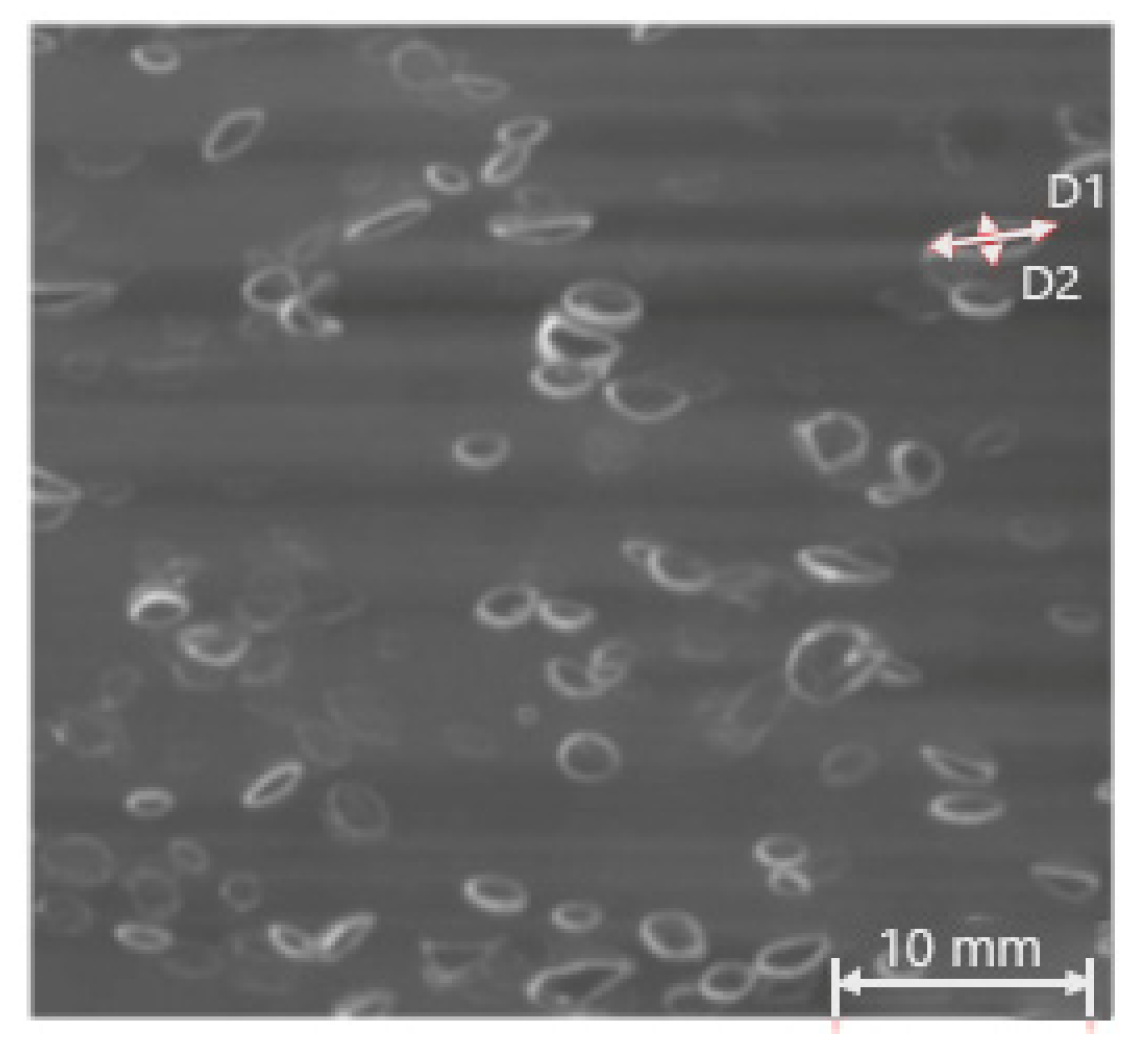
During the experiments, spherical, spheroid, and spherical-cap bubbles were detected. Each bubble had a different form; therefore, two different diameters (i.e., D1 and D2) were measured (see Figure 2). D1 is the largest diameter of the bubble, while D2 is the smallest. According to Equation (16):
D v = ( D 1 2 · D 2 ) 1 3
where the equivalent diameter (Dv) can be found. Dv was used for the further analysis. The bubble size was measured only in the axial position in the plume.
Figure 3 shows a dependence of the bubble equivalent diameter Dv on the gas flow rate, stirring gas (Figure 3a), and plug diameter (Figure 3b). By increasing the gas flow rate, the equivalent diameter increased for both argon and helium as well as for different plug diameters. The bubble equivalent diameter increased approximately linearly with an increase of a gas flow rate. It is also seen that the diameter of the helium bubbles was slightly larger—about 10% more—at gas flow rates higher than 50 L/h at 3 atm pressure. At low gas flow rates, this effect was not visible. The porous plug diameter had a stronger impact on the bubble equivalent diameter. When blowing with a 20 mm plug, bubbles were much larger than the ones with a 30 mm plug at the same flow rates and gas densities. An average value of the equivalent diameter was determined from a minimum of 100 pictures. The standard deviations were between 0.2 and 0.8 mm.

3.2. Bubble Velocity

In this series of experiments, the rising velocities of single bubbles were determined using a high-speed camera (Casio EX-F1, Amazon). It should be noted that the rates were determined in the axis of the bubble plume, i.e., all values of a single bubble rate refer to axial bubble rise velocities. The bubble velocity was calculated using a simple correlation between the camera frame rate (time) and bubble travelling distance. For the distance calculation, the ruler was installed in the middle of the water model. All recordings were made at a rate of 600 fps. An average value of the bubble velocity was determined from a minimum of 100 single bubbles.
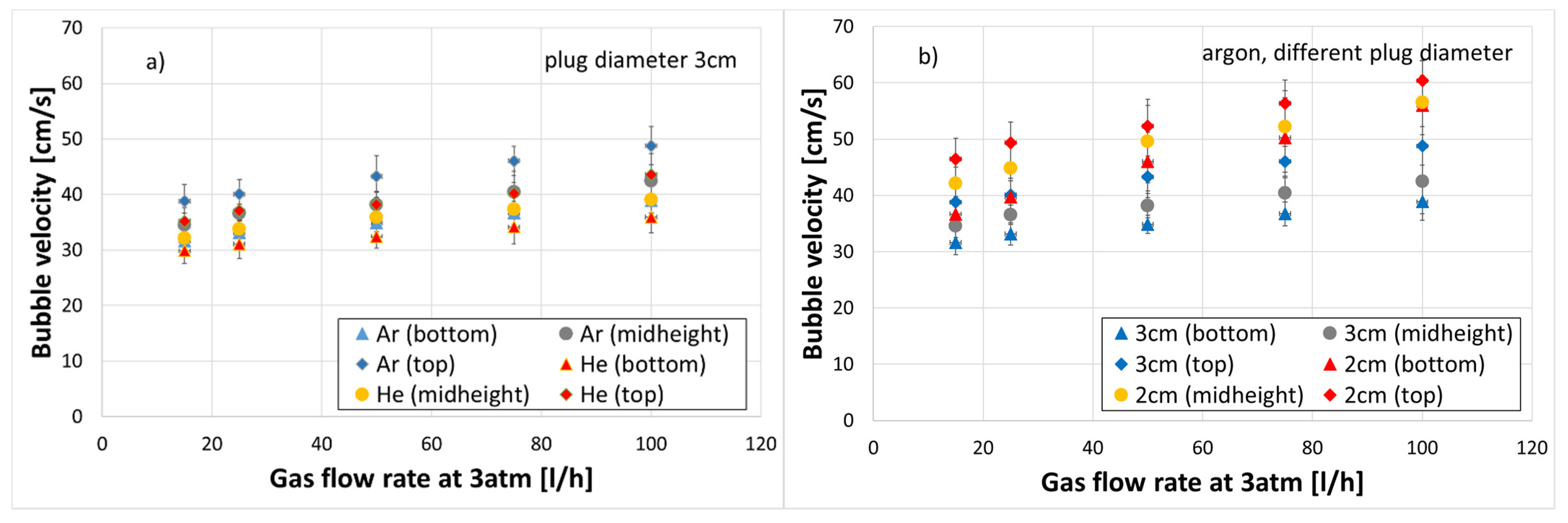
The rising velocities of the bubbles were lower immediately after the plug than at the top of the water model. This can be seen in Figure 4, where the bubble velocities are shown as a function of a distance from the plug, gas flow rate, stirring gas (Figure 4a) and plug diameter (Figure 4b). Increasing the plug diameter reduced the velocity of single bubbles. The registered standard deviations indicated good accuracy and reproducibility of the experiments.
The difference in bubble velocities were observed in the experiments with helium, where stirring with helium caused a lower velocity of individual bubbles compared with argon bubbles. Thereby, the bubble velocity and gas flow rate demonstrated a linear dependence.

3.3. Gas Hold-Up

Figure 5 illustrates a relationship between the axial gas hold-up in a bubble plume and gas flow rate for the three different water model zones with stirring gases argon and helium (Figure 5a) as well as with a nozzle of 20 and 30 mm (Figure 5b). The highest gas quantity appeared shortly after bubbles leave the nozzle. It then decreased approximately linearly with a height of the vessel. The gas hold-up increased by increasing the gas flow rate. Herewith, the axial gas hold-up was higher for helium as a stirring gas than argon within all conducted experiments. Moreover, the higher axial gas hold-up was detected for the 20 mm porous plug in comparison to 30 mm.

3.4. Expansion Angle

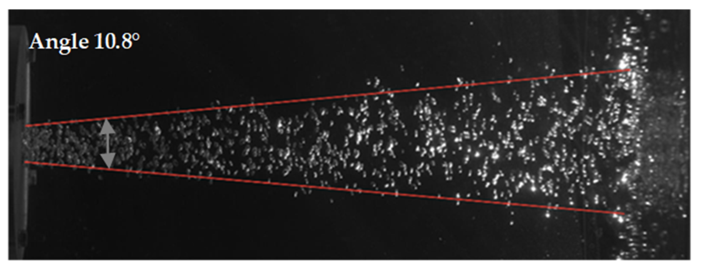
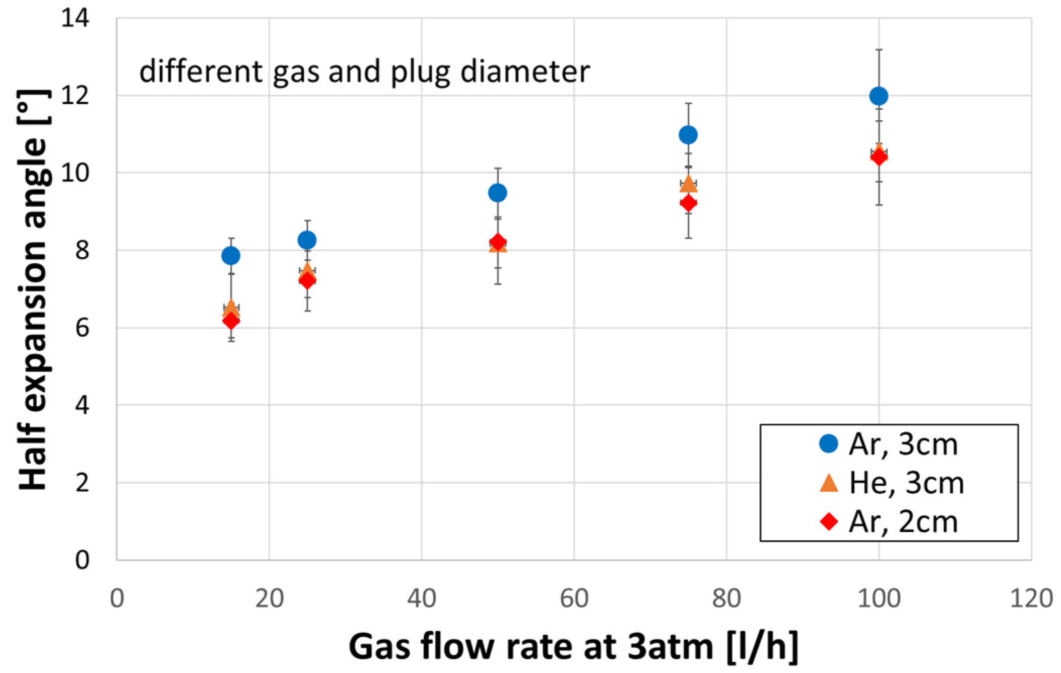
The expansion angle of the bubble swarm appeared to depend on the volume of gas bubbles and nozzle distance, Figure 6. When measuring the angle, a plume area with a minimum of 95% of all bubbles was taken automatically by image analysis software. The individual bubbles out of the plume were not taken into account. The mean value of the expansion angle was calculated from up to 100 measured values. Due to the symmetry of the bubble swarm, the half-expansion angle was utilised for representation (see Figure 7). Thereby, the half-expansion angle decreased with reducing the plug diameter. Meanwhile, the maximum value of the half-expansion angle was approx. 10.4° for a case of the 2 cm nozzle diameter, gas flow rate of 100 L/h, and 3 atm pressure. The linear dependence between the expansion angle and gas flow rate remained after a change of the nozzle diameter from 30 to 20 mm. The tests with helium resulted in the same linear relationship with a gas flow rate (see Figure 7). Stirring with helium compared to argon caused the bubble swarm to spread at a lower angle. The gas introduction with helium covered values between 6.5 and 10.5° for the flushing range used.

3.5. Spout Geometry

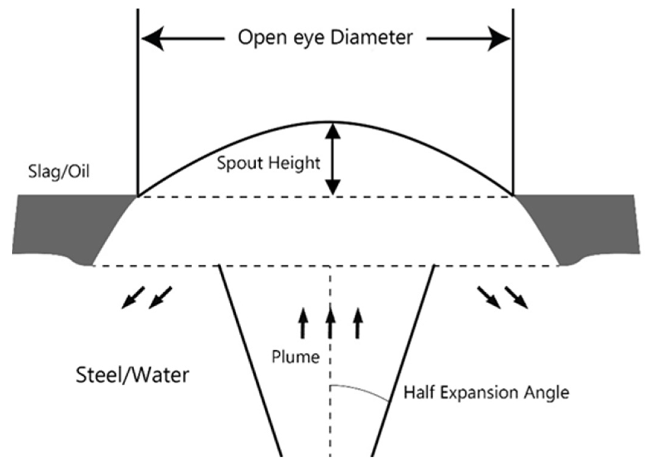
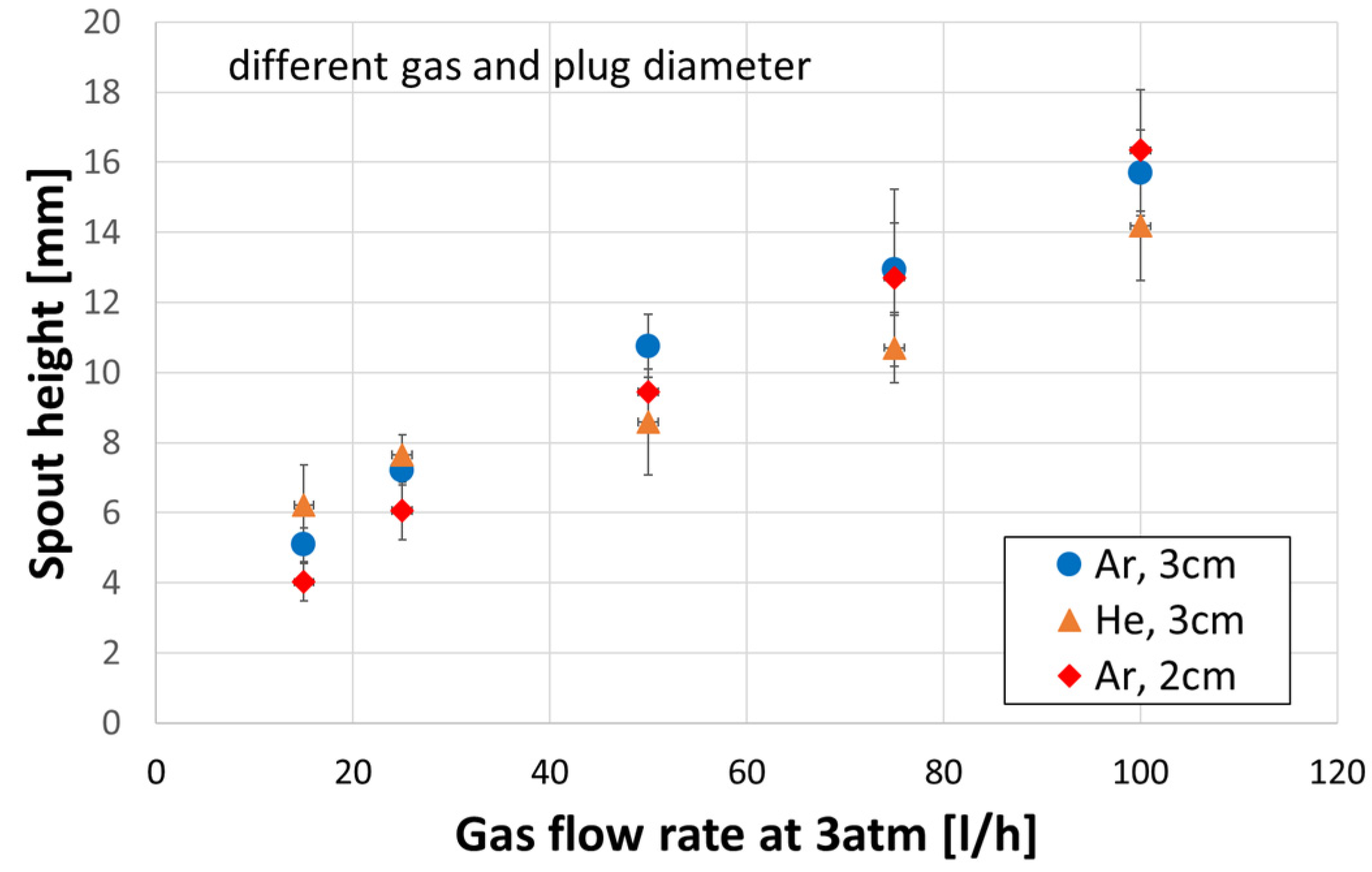
The spout height (see Figure 8) increased linearly with the argon flow rate (see Figure 9). The variation of nozzle diameters regarding the spout height led to the conditions illustrated in Figure 9. It can be assumed that the nozzle diameter had a negligible influence on the spout height. By stirring with helium instead of argon, the values of spout height were in the range of standard deviation. A clear dependence of the open eye height on the gas type was indistinguishable.
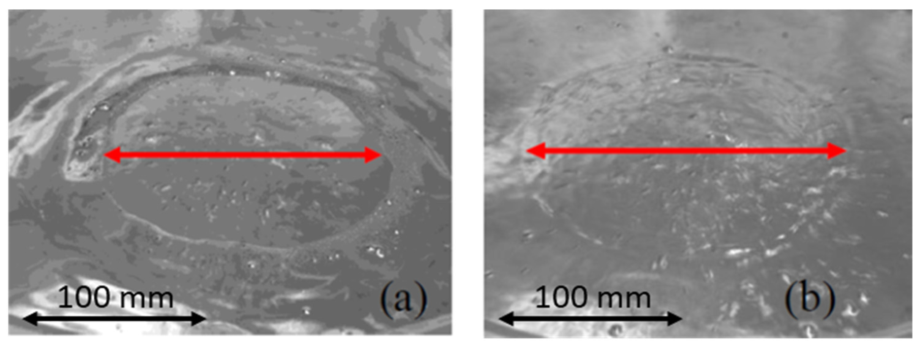
A layer of oil on a surface of the water bath can make contours of the open eye clearer (see Figure 10). However, to avoid an influence of the oil layer on geometry of the open eye, all investigations in this work were carried out without an oil layer. Figure 11 illustrates the relationship between the open eye area and gas flow rate. The open eye increased from about 10,000 mm2 at 15 L/h continuously up to about 50,000 mm2 at 100 L/h. Since the open eye was circular in the images, it corresponded to a diameter of 113 and 252 mm. The low standard deviations of about 500 to 3000 mm2 demonstrated the good reproducibility of the results. The plug diameter also influenced the open eye area. With a reduction in plug diameter, the open eye decreased. The linear relationship between the open eye and gas flow rate was maintained. By stirring with helium, there was no clear difference to the values obtained with argon by using the same plug diameter. All values were in the range of standard deviation.

4. Discussion

Investigations of the ladle stirring process in this work were carried out in a water model of a 30 t ladle with a geometric similarity of 4.5. Argon and helium were used as stirring gases. The gas was supplied to the model through a ceramic porous plug with diameters of 20 and 30 mm. The gas flow rate was set in relation to the real objects based on the modified Mo number (see Equation (6)) [45]. The gas flow rates calculated with the modified Mo number were much lower than the ones calculated with other similarity criteria (see Table 2). In order to assess the effect of the injected gas density and nozzle diameter, all experiments were carried out with the same gas flow rates. According to Krishnapisharody et al. [10], the density and diameter do not influence the plume behaviour. Both utilised gases by leaving pores of the porous plug form bubbles that separate from the plug or coalescence into larger ones, separate, and break up. According to the Anagbo et al. [14] classification, these bubbles on the nozzle/plug as well as the ones that come off the nozzle/plug are called primary and free bubbles. Anagbo et al. [14] stated that the effect of the gas kinetic energy is most pronounced in the primary bubble region and decays rapidly in the free bubble zone. Furthermore, the bubbles move up, merge, expand, break up, and form a bubble plume. The region raised on a bath surface by escaping gas bubbles is called the spout. Iguchi et al. [22] classified the flow field in bubbling jets based on axial changes in the plume velocity and gas hold-up into 4 regions: the momentum, transition, buoyancy, and surface regions from the nozzle exit toward the bath surface. The average axial size and velocity of the bubbles in this work were measured along the height of the bath, but only in the plume/buoyancy region.
The density of helium is 10 times less than the density of argon (see Table 3). Therefore, the kinetic energy of argon gas was greater than the kinetic energy of helium for the same volumetric flow rates, nozzles/plug sizes, and exit velocity on the plug. According to Equation (17) for the dimensionless gas fraction in the plume α ¯ e , the gas velocity drops to 1% of the initial value [10]:
α ¯ e = [ 1 + 100 · ρ g ρ l ] 1
The velocity of argon bubbles dropped to 1% of the initial value by a gas fraction of 0.86 and velocity of helium gas by a gas fraction of 0.98. Thus, helium bubbles slowed down, lost their velocity earlier and closer to the plug, and then floated up slower than argon bubbles. Therefore, the helium bubble velocity was lower than the one of argon bubbles along the bath height (see Figure 4a), which differs from the results in [13]. Experiments with helium and nitrogen in [13] showed that the gas density influences the bubble velocity only up to 100 mm away from the nozzle. After 100 mm, the velocity of helium bubbles was the same as the velocity of nitrogen bubbles. The experiments in [13] were carried out with nozzle diameters of 1.85 and 4 mm, which is lower than those in the current study. Moreover, the gas flow rate was 3–9 times higher compared to the maximum gas flow rate in the current study.
Due to a decrease in ferrostatic pressure along a height of the bath, the bubbles expand along the height and, thus, the density of the bubbles decreases and the bubbles also move faster (see Figure 3 and Figure 4).
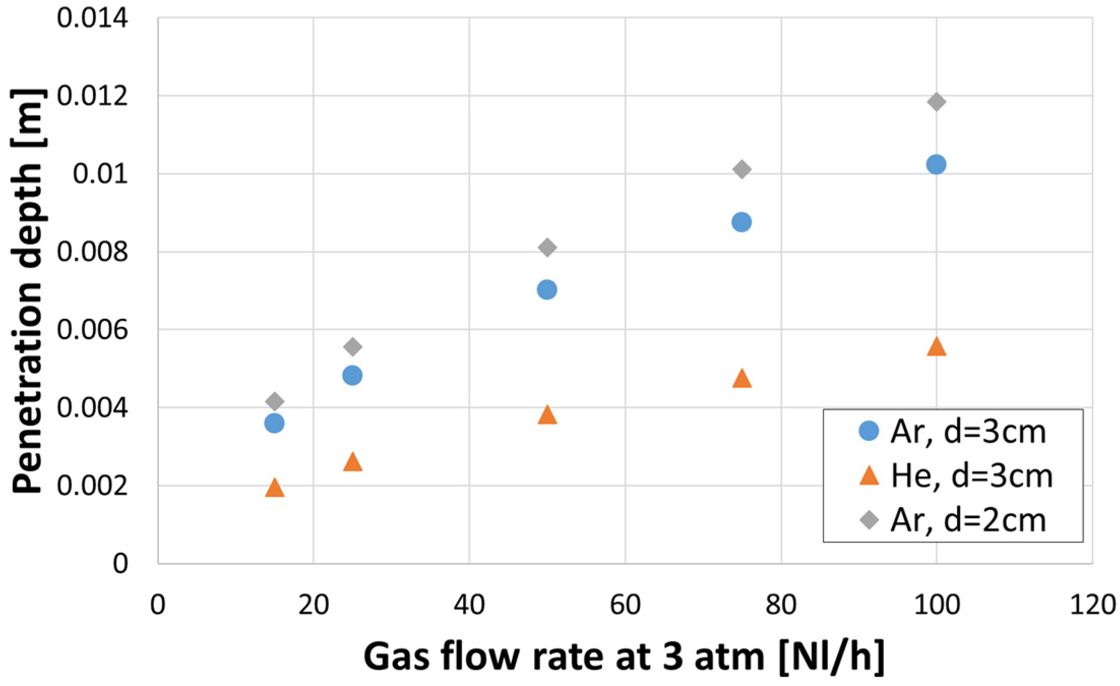
With an increase in gas consumption, the gas initial kinetic energy increases. Schwerdtfeger et al. [31,32,33] defined the penetration depth z 0 , described by Equation (18), as the point where the axial gas hold-up drops to 50% when the transition between momentum jet and buoyancy region occurs:
z 0 = d · 6.8 · ( Q 2 · ρ g g · d 5 · ρ l ) 0.272
The advantage of Equation (18) over Equation (17) is that it allows estimating the effect of the nozzle/plug diameter and gas flow rate on the plume behaviour (see Figure 12). Thereby, the penetration depth (i.e., length of the momentum jet) increased with a decrease of the plug diameter and increase of the gas flow rate. This led to an increase in the bubble diameter and bubble velocity.
The expansion angle of the bubble plume increased with the gas flow rate, but it also demonstrated a dependence on the plug diameter (Figure 7). As the diameter of the porous plug decreased, the expansion angle decreased, as shown by an area of the open eye (see Figure 11). The velocity of helium bubbles was small, so the helium bubble plume expanded slightly leading to a lower half-expansion angle of the helium plume under the same conditions as the argon plume (see Figure 7). This, however, does not match the results from [31], where the helium/water jet expanded more rapidly than air/water jets.
Helium bubbles moved more slowly than argon ones. Thereby, the helium plume expanded less than the argon plume. Thus, the helium bubbles most likely have more favourable conditions for expansion and coalescence in comparison to argon bubbles. It was reflected in larger helium bubbles compared to argon bubbles (see Figure 3). The larger bubbles in the helium/water system compared to bubbles in the air/water system were also found in [31]. Furthermore, the gas hold-up of the helium plume was higher than the argon plume (see Figure 5). Nevertheless, an area of the open eye was practically independent of the physical properties of the injected gas (see Figure 11).
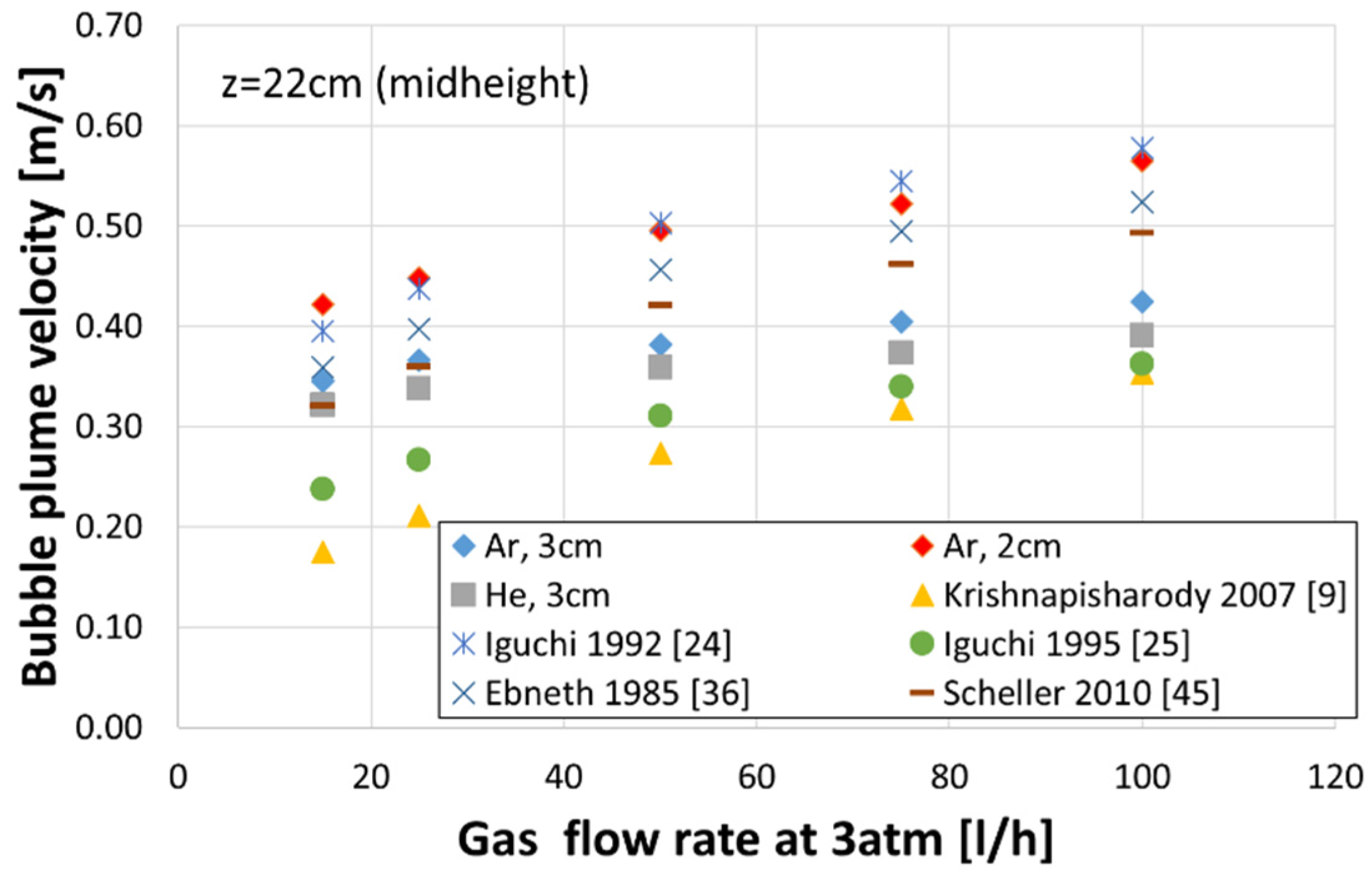
The experimentally obtained bubble velocity in the plume centre was compared with the data from the literature (see Figure 13). Thereby, the following known equations for the axial bubble plume velocity were used:
Krishnapisharody et al. [9]
v B u b b l e   p l u m e = 7.3 · Q 0.37 · z 0.43 ,   [ m s ]
Iguchi et al. [24]
v B u b b l e   p l u m e = 53 · ( Q 2 g ) 0.1 ,   [ cm s ]
Iguchi et al. [25]
v B u b b l e   p l u m e = 1.24 · ( g · Q z ) 1 / 3 · ( ( Q 2 g · z 5 ) 1 / 5 ) 0.28 ,   [ m s ]
Ebneth et al. [36]
v B u b b l e   p l u m e = 3.81 · Q 0.2 · z 0.003 ,   [ m s ]
Scheller et al. [45]
v B u b b l e   p l u m e = 38.784 · Q 0.226 ,   [ cm s ]
where z is axial coordinate in [m] or [cm]. In Equation (23) the gas flow rate has unit [L/min].
From Figure 13, the literary equations give different results for the same gas flow rates. These equations do not take into account the gas density or nozzle/plug diameter.

5. Conclusions

The present work deals with investigations of the ladle stirring process using a water model of a 30 t ladle with a geometric similarity of 4.5. Thereby, the effect of the injected gas density and nozzle diameter was studied. Prior to experiments, the known similarity criteria from the literature, which were used for investigation of stirring processes in a ladle, were reviewed and compared. Unfortunately, different criteria predicted totally different gas consumption on the water model when modelling the processes in an industrial ladle. Based on this review, the modified Morton number was chosen for the current study to relate the gas flow rate in the model to real objects. In order to assess the effect of the injected gas density and nozzle diameter, all experiments were carried out with the same gas flow rates. Based on the experimental results, the following conclusions can be formulated:
  • It was observed that, regardless of the gas density, an increase in a gas flow caused an increase in a bubble diameter.
  • Diameter of the gas bubbles formed when helium was used was about 10% greater in comparison to argon, but only for a gas flow rate greater than 50 L/h.
  • Regardless of the gas density, the diameters of bubbles were larger for the porous plug with a smaller diameter (20 mm) for the same gas flow rate. This means that in the real process, an enlargement of the plug diameter due to erosion can result in poorer mixing conditions due to lower kinetic energy of the bubbles with smaller diameters.
  • Increasing the plug diameter reduced the bubble rising velocity. The helium bubble velocities were lower than those of the argon bubbles for the same gas flow rate and plug diameter.
  • Axial gas hold-up in case of helium as a stirring gas was higher every time in comparison to argon for all conducted experiments.
  • As the porous plug diameter decreased from 30 to 20 mm, the axial gas hold-up increased.
  • Stirring with helium compared to argon caused the bubble swarm to spread at a lower angle in the liquid.
  • Spout height increased with a gas flow rate. The plug diameter had a negligible influence on the spout height.
  • There was no effect of the gas density on the open eye formation, unlike the plug diameter, where a smaller plug produced a smaller open eye at the surface area, which was expected and consistent with the industrial practice.
  • The velocities of gas bubbles in the plume measured in this work were compared to results in the literature, which were obtained on water models using nozzles of a few millimetres size and various similarity criteria. Unfortunately, the studies utilised for comparison have not considered the gas density or nozzle diameter and provided quite variable predictions.

Author Contributions

Conceptualization, D.R. and O.V.; methodology, D.R. and O.V.; software, D.R. and M.M.G.; validation, D.R. and O.V.; formal analysis, D.R., T.K. and O.V.; experimental investigation, D.R.; resources, D.R. and O.V.; data curation, D.R. and O.V.; writing—original draft preparation, O.V.; writing—review and editing, M.M.G., T.K., O.V.; visualization, T.K. and O.V.; supervision, O.V.; project administration, O.V. All authors have read and agreed to the published version of the manuscript.

Funding

This work was executed in the Institute of Iron and Steel Technologies. Open Access Funding by the Publication Fund of the TU Bergakademie Freiberg.

Institutional Review Board Statement

Not applicable.

Informed Consent Statement

Not applicable.

Data Availability Statement

Data and results reported in this work can be accessed on demand from the authors.

Conflicts of Interest

The authors declare no conflict of interest.

References

  1. Irons, G.A.; Guthrie, R.I.L. Bubble Formation at Nozzles in Pig Iron. Metall. Trans. B 1978, 9, 101–110. [Google Scholar] [CrossRef]
  2. Sahai, Y.; Guthrie, R.I.L. Hydrodynamics of Gas Stirred Melts: Part II. Axisymmetric Flows. Metall. Trans. B 1982, 13, 203–211. [Google Scholar] [CrossRef]
  3. Sheng, Y.Y.; Irons, G.A. Measurement and Modeling of Turbulence in the Gas/Liquid Two-Phase Zone during Gas Injection. Metall. Trans. B 1993, 24, 695–705. [Google Scholar] [CrossRef]
  4. Sheng, Y.Y.; Irons, G.A. The Impact of Bubble Dynamics on the Flow in Plumes of Ladle Water Models. Metall. Mater. Trans. B 1995, 26, 625–635. [Google Scholar] [CrossRef]
  5. Kapoor, A.; Irons, G.A. A Physical Modeling Study of Fluid-flow Phenomena in Gas-Slag Systems. ISIJ Int. 1997, 37, 829–838. [Google Scholar] [CrossRef]
  6. Guo, D.; Irons, G.A. Modeling of Gas-Liquid Reactions in Ladle Metallurgy: Part 1. Physical Modeling. Metall. Trans. B 2000, 31, 1447–1455. [Google Scholar] [CrossRef]
  7. Krishnapisharody, K.; Irons, G.A. A Study on Bath Surfaces from Gas Bubbling: Part II. Elucidation of Plume Dynamics Metall. Mater. Trans. B 2007, 38, 377–388. [Google Scholar] [CrossRef]
  8. Krishnapisharody, K.; Irons, G.A. Modeling of Slag Eye Formation over a Metal Bath Due to Gas Bubbling. Metall. Trans. B 2006, 37, 763–772. [Google Scholar] [CrossRef]
  9. Krishnapisharody, K.; Irons, G.A. A Study on Bath Surfaces from Gas Bubbling: Part I. Experimental Investigation Metall. Mater. Trans. B 2007, 38, 367–375. [Google Scholar] [CrossRef]
  10. Krishnapisharody, K.; Irons, G.A. A Critical Review of the Modified Froude Number in Ladle Metallurgy. Metall. Trans. B 2013, 44, 1486–1498. [Google Scholar] [CrossRef]
  11. Krishnapisharody, K.; Irons, G.A. A model for Slag Eyes in Steel Refining Ladles Covered with Thick Slag. Metall. Trans. B 2015, 46, 191–198. [Google Scholar] [CrossRef]
  12. Castillejos, A.H.; Brimacombe, J.K. Measurement of Physical Characteristics of Bubbles in Gas-Liquid Plumes: Part II. Local Properties of Turbulent Air-Water Plumes in Vertically Injected Jets. Metall. Trans. B 1987, 18, 659–671. [Google Scholar] [CrossRef]
  13. Catillejos, A.H.; Brimacombe, J.K. Physical Characteristics of Gas Jets Injected Vertically Upward into Liquid Metal. Metall. Trans. B 1989, 28, 595–601. [Google Scholar] [CrossRef]
  14. Anagbo, P.E.; Brimacombe, J.K. Plume Characteristics and Liquid Circulation in Gas Injection through a porous Plug. Metall. Trans. B 1990, 21, 637–648. [Google Scholar] [CrossRef]
  15. Sahajwalla, V.; Castillejos, A.H.; Brimacombe, J.K. The spout of air jets upwardly injected into a water bath. Metall. Trans. B 1990, 21, 71–80. [Google Scholar] [CrossRef]
  16. Zhou, M.; Brimacombe, J.K. Critical Fluid-Flow Phenomenon in a Gas-Stirred Ladle. Metall. Mater. Trans. B 1994, 25, 681–693. [Google Scholar] [CrossRef]
  17. Mazumdar, D. Dynamic Similarity Considerations in Gas-Stirred Ladle Systems. Metall. Trans. B 1990, 21, 925–928. [Google Scholar] [CrossRef]
  18. Mazumdar, D.; Kim, H.B.; Guthrie, R.I.L. Modelling criteria for flow simulation in gas stirred ladle systems: An experimental study. ISIJ Int. 2000, 27, 302–309. [Google Scholar] [CrossRef]
  19. Mazumdar, D. On the Estimation of Plume Rise Velocity in Gas-Stirred Ladles. Metall. Mater. Trans. B 2002, 33, 937–941. [Google Scholar] [CrossRef]
  20. Conejo, A.N.; Mishra, R.; Mazumdar, D. Effects of Nozzle Radial Position, Separation Angle, and Gas Flow Partitioning on the Mixing, Eye Area, and Wall Shear Stress in Ladles Fitted with Dual Plugs. Metall. Mater. Trans. B 2019, 50, 1490–1502. [Google Scholar] [CrossRef]
  21. Kim, S.H.; Fruehan, R.J. Physical Modeling of Liquid/Liquid Mass Transfer in Gas Stirred Ladles. Metall. Trans. B 1987, 18, 381–390. [Google Scholar] [CrossRef]
  22. Iguchi, M.; Takeuchi, H.; Morita, Z. The Flow Field in Air-Water Vertical Bubbling Jets in a Cylindrical Vessel. ISIJ Int. 1991, 31, 246–253. [Google Scholar] [CrossRef]
  23. Iguchi, M.; Nozawa, K.; Tomida, H.; Morita, Z. Bubble Characteristics in the Buoyancy Region of a Vertical Bubbling Jet. ISIJ Int. 1992, 32, 747–754. [Google Scholar] [CrossRef] [Green Version]
  24. Iguchi, M.; Demoto, Y.; Sugawara, N.; Morita, Z. Bubble Behavior in Hg-Air Vertical Bubbling Jets in a Cylindrical Vessel. ISIJ Int. 1992, 32, 998–1005. [Google Scholar] [CrossRef] [Green Version]
  25. Iguchi, M.; Kondoh, T.; Morita, Z.; Nakajima, K.; Hanazaki, K.; Uemura, T.; Yamamoto, F. Velocity and Turbulence Measurements in a Cylindrical Bath Subject to Centric Bottom Gas Injection. Metall. Mater. Trans. B 1995, 26, 241–247. [Google Scholar] [CrossRef]
  26. Iguchi, M.; Kawabata, H.; Nakajima, K.; Morita, Z. Measurement of Bubble Characteristics in a Molten Iron Bath at 1600 °C Using an Electroresistivity Probe. Metall. Mater. Trans. B 1995, 26, 67–74. [Google Scholar] [CrossRef]
  27. Iguchi, M.; Tokunaga, H. Molten Wood’s-Metal Flow in a Cylindrical Bath Agitated by Cold Bottom-Gas Injection. Metall. Mater. Trans. B 2002, 33, 695–702. [Google Scholar] [CrossRef]
  28. Iguchi, M.; Miyamoto, K.; Yamashita, S.; Iguchi, D.; Zeze, M. Spout Eye Area in Ladle Refining Procee. ISIJ Int. 2004, 44, 636–638. [Google Scholar] [CrossRef]
  29. Xie, Y.; Orsten, S.; Oeters, F. Behaviour of Bubbles at Gas Blowing into Liquid Wood’s Metal. ISIJ Int. 1992, 32, 66–75. [Google Scholar] [CrossRef] [Green Version]
  30. Xie, Y.; Oeters, F. Measurements of bubble plume behaviour and flow velocity in gas stirred liquid Wood’s metal with an eccentric nozzle position. Steel Res. 1994, 65, 315–319. [Google Scholar] [CrossRef]
  31. Tacke, K.H.; Schubert, H.G.; Weber, D.J.; Schwerdtfeger, K. Characteristics of Round Vertical Gas Bubble Jets. Metall. Trans. B 1985, 16, 263–275. [Google Scholar] [CrossRef]
  32. Castello-Branco, M.A.S.C.; Schwerdtfeger, K. Lagre-Scale Measurements of the Physical Characteristics of Round Vertical Bubble Plumes in Liquids. Metall. Mater. Trans. B 1994, 25, 359–371. [Google Scholar] [CrossRef]
  33. Castello-Branco, M.A.S.C.; Schwerdtfeger, K. Characteristics of Eccentric Bubble Plumes in Liquids. Metall. Mater. Trans. B 1996, 27, 231–239. [Google Scholar] [CrossRef]
  34. Yonezawa, K.; Schwerdtfeger, K. Spout Eyes Formed by a Emerging Gas Plume at the Surface of a Slag-Covered Metal Melt. Metall. Mater. Trans. B 1999, 30, 411–418. [Google Scholar] [CrossRef]
  35. Yonezawa, K.; Schwerdtfeger, K. Dynamics of the Spout of Gas Plumes Discharging from a Melt: Experimental Investigation with a Large-Scale Water Model. Metall. Mater. Trans. B 2000, 31, 461–468. [Google Scholar] [CrossRef]
  36. Ebneth, G.; Pluschkell, W. Dimensional analysis of the vertical heterogeneous buoyant plume. Steel Res. 1985, 56, 513–518. [Google Scholar] [CrossRef]
  37. Steinmetz, E.; Scheller, P.R. Beitrag zu den Stroemungsverhaeltnissen in einer Spuelsteinpfanne. Stahl Eisen 1881 1987, 107, 57–65. [Google Scholar]
  38. Kargul, T.; Falkus, J. A Hybrid Model of Steel Refining in The Ladle Furnace. Steel Res. Int. 2010, 81, 953–958. [Google Scholar] [CrossRef]
  39. Liu, Y.; Ersson, M.; Liu, H.; Jönsson, P.G.; Gan, Y. A Review of Physical and Numerical Approaches for the Study of Gas Stirring in Ladle Metallurgy. Metall. Mater. Trans. B 2019, 50, 555–577. [Google Scholar] [CrossRef] [Green Version]
  40. Pan, Y.; Guo, D.; Ma, J.; Wang, W.; Tang, F.; Li, C. Mixing Time and Fluid Flow Pattern of Composition Adjustment by Sealed Argon Bubbling with Ladles of Large Height/Diameter Ratio. ISIJ Int. 1994, 34, 794–801. [Google Scholar] [CrossRef]
  41. Ek, M.; Wu, L.; Valentin, P.; Sichen, D. Effect of Inert Gas Flow Rate on Homogenization and Inclusion Removal in a Gas Stirred Ladle. Steel Res. Int. 2010, 81, 1056–1063. [Google Scholar] [CrossRef]
  42. Smirnov, A.; Eronko, S.; Kovalenko, I.; Giessen, R. Optimization of argon-injection process parameters for ladle treatment of steel. In Proceedings of the EOSC, 5th European Oxygen Steelmaking Conference, Aachen, Germany, 26–28 July 2006; pp. 272–279. [Google Scholar]
  43. Krishna Murthy, G.G.; Ghosh, A.; Mehrotra, S.P. Mathematical Modeling of Mixing Phenomena in a Gas Stirred Liquid Bath. Metall. Trans. B 1989, 20, 53–59. [Google Scholar] [CrossRef]
  44. Krishna Murthy, G.G.; Ghosh, A.; Mehrotra, S.P. Characterization of Two-Phase Axisymmetric Plume in a Gas Stirred Liquid Bath—A Water Model Study. Metall. Trans. B 1988, 19, 885–892. [Google Scholar] [CrossRef]
  45. Scheller, P.; Volkova, O.; Ryabov, D. Plume Characteristics in Gas Stirred Ladles. In Jim Evans Honorary Symposium. Proceedings of the TMS Annual Meeting; Wiley: Hoboken, NJ, USA, 2010; pp. 165–172. [Google Scholar]
  46. Yu, S.; Zou, Z.S.; Shao, L.; Louhenkilpi, S. A Theoretical Scaling Equation for Designing Physical Modeling of Gas-Liquid Flow in Metallurgical Ladles. Steel Res. Int. 2017, 88, 1600156. [Google Scholar] [CrossRef]
  47. Bohl, W. Technische Strömungslehre: Stoffeigenschaften von Flüssigkeiten und Gasen, Hydrostatik, Aerostatik, Inkompressible Strömungen, Kompressible Strömungen, Strömungsmesstechnik; 11 Durchges. Aufl.; Vogel Buchverlag: Würzburg, Germany, 1978. [Google Scholar]
  48. Shukla, A.K.; Ryabov, D.; Volkova, O.; Scheller, P.R.; Deo, B. Cold Model Investigations of Melting of Ice in as Gas-Stirred Vessel. Metall. Mater. Trans. B 2011, 42, 224–235. [Google Scholar] [CrossRef]
Figure 1. Experimental setup.
Crystals 11 00475 g001
Figure 2. Measuring of bubble equivalent diameter.
Crystals 11 00475 g002
Figure 3. Equivalent bubble diameter as a function of gas flow rate, stirring gas types (a) and plug diameter (b).
Crystals 11 00475 g003
Figure 4. Bubble velocity as a function of gas flow rate, stirring gas types (a) and plug diameter (b).
Crystals 11 00475 g004
Figure 5. Gas hold-up as a function of gas flow rate, stirring gas types (a) and plug diameter (b).
Crystals 11 00475 g005
Figure 6. Determination of expansion angle.
Crystals 11 00475 g006
Figure 7. Half-expansion angle as a function of gas flow rate for different plug diameters and stirring gas types.
Crystals 11 00475 g007
Figure 8. Schematic representation of the open eye/spout in the presence of a top slag/oil layer.
Crystals 11 00475 g008
Figure 9. Spout height as a function of gas flow rate for different plug diameters and stirring gas types.
Crystals 11 00475 g009
Figure 10. Open eye (a) with and (b) without silicon oil layer on surface.
Crystals 11 00475 g010
Figure 11. Open eye area as a function of gas flow rate for different plug diameters and stirring gas types.
Crystals 11 00475 g011
Figure 12. Penetration depth z 0 as a function of stirring gas, plug diameter, and gas flow rate calculated with Equation (18).
Crystals 11 00475 g012
Figure 13. Comparison of measured and calculated bubble plume velocity.
Crystals 11 00475 g013
Table 1. Previous cold and hot model investigations of ladle gas stirring process (EP—electroresistivity probe, LDV—laser doppler velocimeter, MIA—multivariate image analysis, PCA—principal component analysis, MP—magnet probe, LDA—laser doppler anemometry, CCD—charge coupled device).
Ref.D × H [mm]SystemGas Inlet, d [mm]MethodGas Flow RateResults
Irons 1978 [1]-Pig iron/argonLance/nozzleAcoustic device1–1000 [cm3/s]Bubble frequency, bubble diameter
Sahai 1982 [2]500 × 450Water/air/small rectangular cardsVertical lance, 2.16 Video recordings4.3 × 10−4 [m3/s]Velocity
Ebneth 1985 [36]1440 × 1650Water/airNozzle, 8Propeller flowmeter1.67 × 10−4, 1 × 10⁻³ [m3/s]Plume velocity
Tacke 1985 [31]445 × 600
284 × 270
Water/air, Hg/N2, water/HeNozzle, 0.5–4 EP59–2660 [cm3/s]Bubble hold-up, frequency, bubble diameter
Kim 1987 [21] 456 × 620Water/airNozzle: 2, 4.8Conductivity cell1–10 [L/min]Mixing time
Castillejos 1987 [12] 500 × 400, 500 × 600Water/airNozzle, 4.1, 6.35EP371, 876, 1257 [cm3/s]Gas fraction and velocity, bubble frequency and diameter, gas velocity
Castillejos 1989 [13] 210 × 210Hg/N2, Hg/HeNozzle, 1.85, 4EP158–456 [cm3/s]Gas fraction, frequency and bubble velocity, bubble diameter
Anagbo 1990 [14] 500 × 400Water/airPorous element, 60EP, LDV200–1200 [cm3/s]Gas fraction, gas velocity, liquid velocity
Sahajwalla 1990 [15]500, 400Water/airNozzle, 6.35EP, high-speed camera371, 876, 1257, 1630 [cm3/s]Spout, gas fraction, frequency, velocity of gas
Iguchi 1991 [22]126 × 400
200 × 400
Water/airNozzle, 1, 2, 5EP, LDV10.3, 20.6; 41.4 [cm3/s]Bubble frequency and gas hold-up, bubble velocity
Iguchi 1992 [23]126 × 180, 200 × 385, 390 × 385Water/airNozzle: 1, 2, 4, 5EP, LDV10–100 [cm3/s]Bubble frequency and hold-up, bubble velocity
Iguchi 1992 [24]125 × 145Hg/airNozzle, 0.5, 1.01, 1.53 EP300 [cm3/s]Bubble hold-up, frequency, bubble velocity
Sheng 1993 [3] 500 × 420Water/airNozzleEP, LDA, camera50–200 [mL/s]Gas hold-up, liquid velocity
Pan 1994 [40]280 × 280–400Water/N2NozzleConductivity cell1.14–6 × 10⁻² [m3/h]Mixing time
Zhou 1994 [16]500 × 200, 300, 400Water/airNozzleEP, LDV2 × 10−4–20 × 10−4 [m3/s]Critical gas flow rate
Castello-Branco 1994, 1996 [32,33]1600 × 2250Water/airNozzleEP, propeller flowmeter2500, 5000, 6389, 7222, 7778 [cm3/s]Gas hold-up, bubble frequency, liquid and gas velocities
Sheng 1995 [4]500 × 420Water/airNozzleEP, LDA50–200 [mL/s]Bubble hold-up, frequency, bubble velocity
Iguchi 1995 [25]126 × 233Water/airNozzle: 1, 2, 5EP, LDV10–160 [Ncm3/s]Plume velocity
Yonezawa 1999 [34]290 × 225Hg/N2NozzleCCD camera0.2–0.6 [m3/h]Spout geometry
Mazumdar 2000 [18]300 × 600, 250 × 490Water/ArLanceConductivity cell0.8–3.8 × 10⁻⁴ [m3/s]Mixing time
Guo 2000 [6]420 × 500Water–NaOH/CO2Nozzle, 1. Plug, 10–50PH-probe, video10 [L/min]Bubble behaviour
Yonezawa 2000 [35]1600 × 1800Water/airFlush nozzleCamera, EP5, 9, 18, 26, 28 [m3/h]Spout geometry
Iguchi 2004 [28] 200 × 300, 750
500 × 300, 750
Water/silicon oil/airNozzleCCD camera-Spout geometry
Krishnapi-sharody 2006, 2007, 2015 [8,9,11]420 × 500Water/air/liquid paraffin oilFlush Nozzle, 3CCD camera1–10 [L/min]Spout, open eye geometry
Ek 2010 [41]480 × 500Water/air/silicon oil/charcoal particlesNozzle, 6Conductivity measurement0.15–0.45 [m3/h]Mixing time, removal of non-metallic inclusion
Conejo 2019 [20]335 × 391Water/air–automotive oilNozzel, 3Sensor, camera0–7.8 [NL/min]Mixing time, open eye area
Xie 1992, 1994 [29,30]400 × 370Wood/Ar, N2, HeAccentric nozzleEP, MP100–1200 [cm3/s]Bubble frequency and diameter, gas hold-up, liquid velocity
Iguchi 1995 [26]90 × 120Pig iron/ArNozzle, 1EP50–100 [cm3/s]Diameter, frequency and velocity of bubble
Iguchi 2002 [27]200 × 150Wood/HeNozzle EP60–90 [cm3/s]Gas hold-up, bubble velocity
Table 2. Calculated argon flow rates using different similarity criteria and equations for water model by modelling of 30 t ladle (geometric similarity λ = 4.5, * equation number).
[NL/min]Cold Water Model [L/h], 3 atm
(1) *(2) *(3) *(4) *(6) *(7) *(8) *(9) *(10) *(11) *(13) *(14) *
3512346354615191272827231551
6021179597925332184847402587
120421159118159506643697938050174
1806322381772387510065314514012076261
140843317236317100133871194187161101348
Table 3. Material properties for calculation of argon flow rate in water model [45,47].
Density [kg/m3]Dynamic Viscosity [Pa·s]Surface Tension [kg/s2]
Steel70000.0049981.0
Water998.20.0010010.073
Argon1.662822.7 × 10−6 -
Helium0.1785--
Publisher’s Note: MDPI stays neutral with regard to jurisdictional claims in published maps and institutional affiliations.