
Influence of Gas Density and Plug Diameter on Plume Characteristics by Ladle Stirring


Abstract
:1. Introduction
2. Materials and Methods
- −
- Zone 1 (top): 0–15 cm
- −
- Zone 2 (midheight): 15–30 cm
- −
- Zone 3 (bottom): 30–45 cm
3. Results
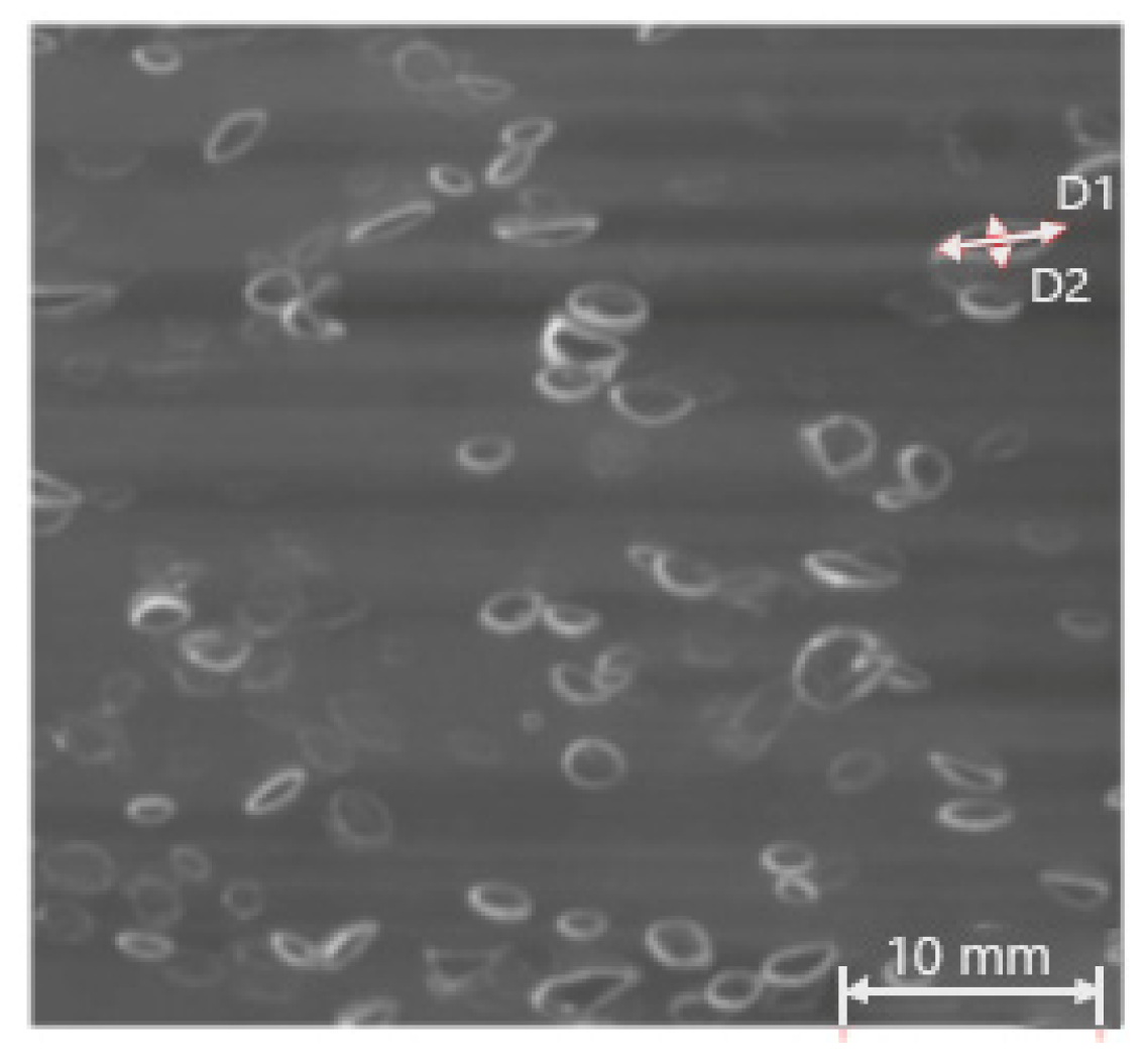
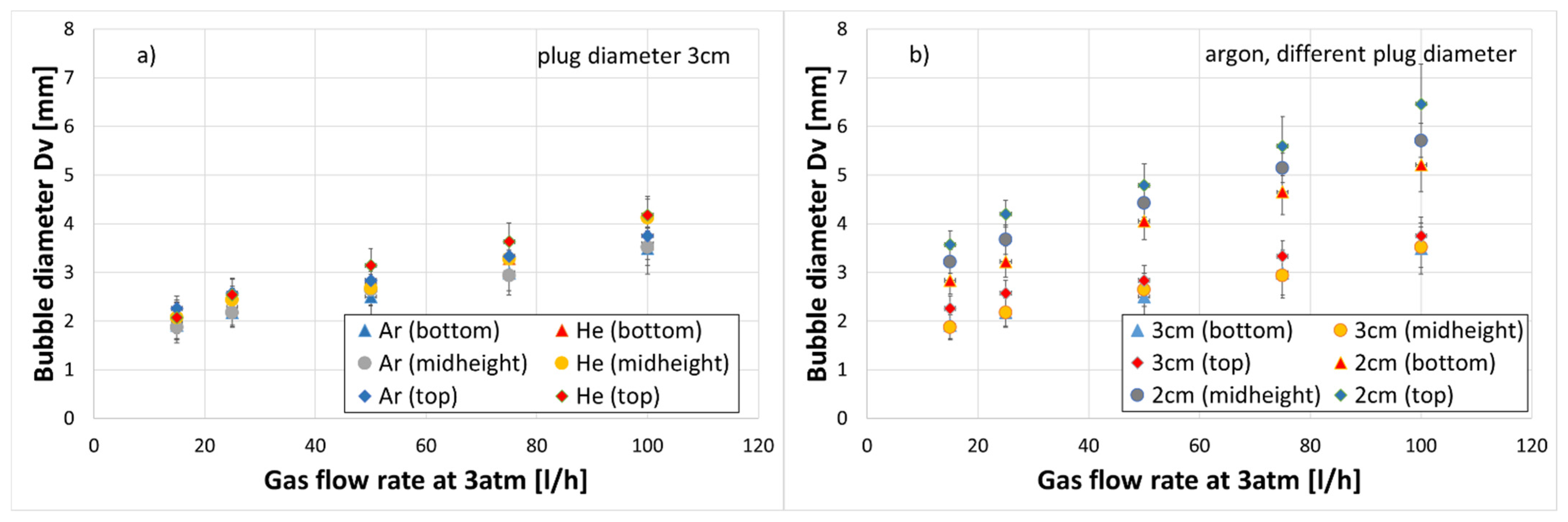
3.1. Bubble Size
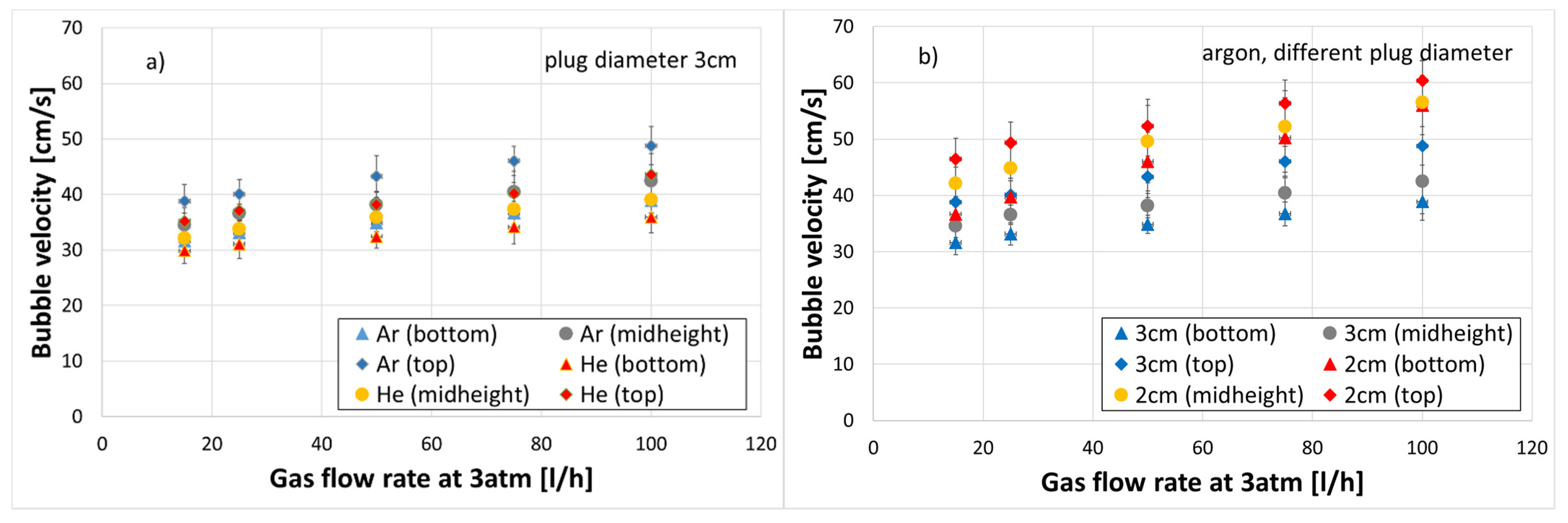
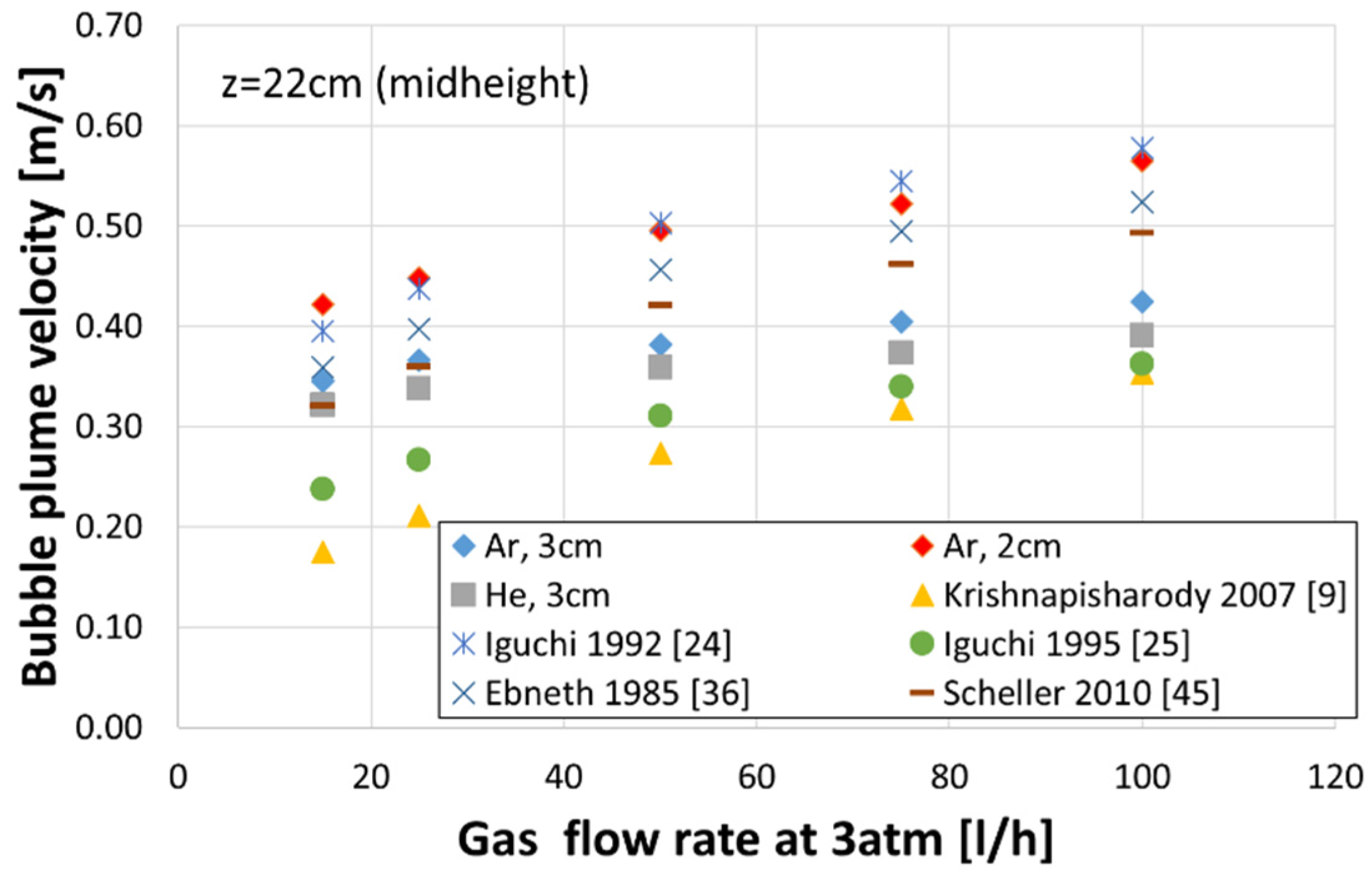
3.2. Bubble Velocity
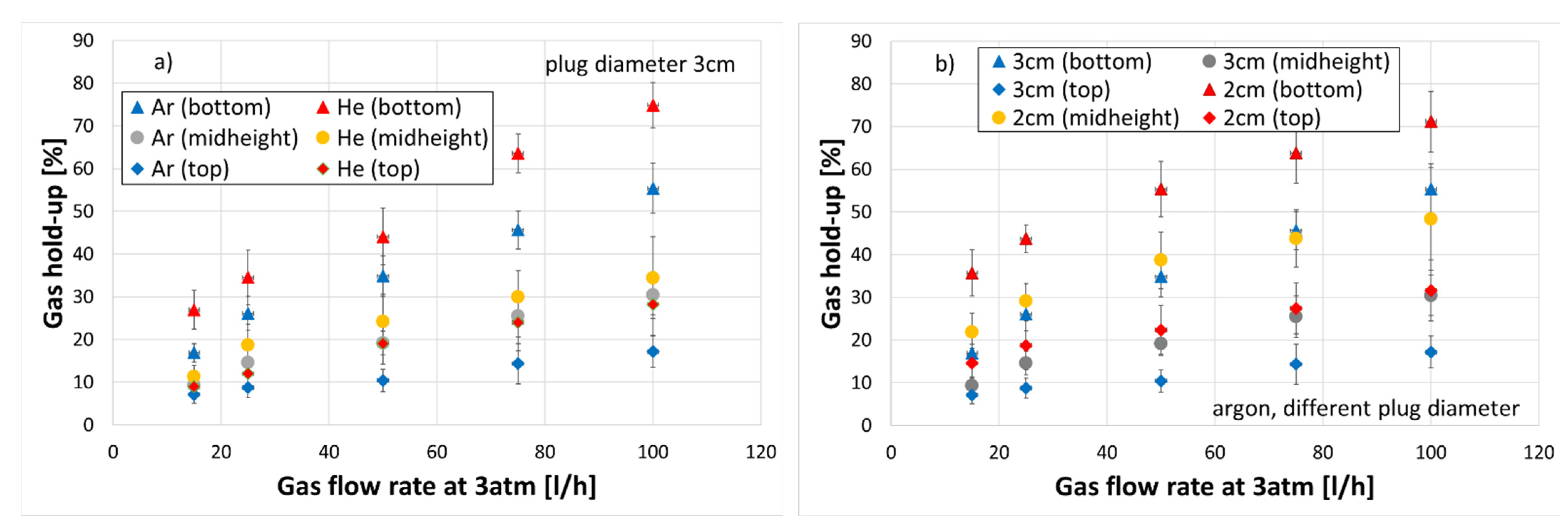
3.3. Gas Hold-Up
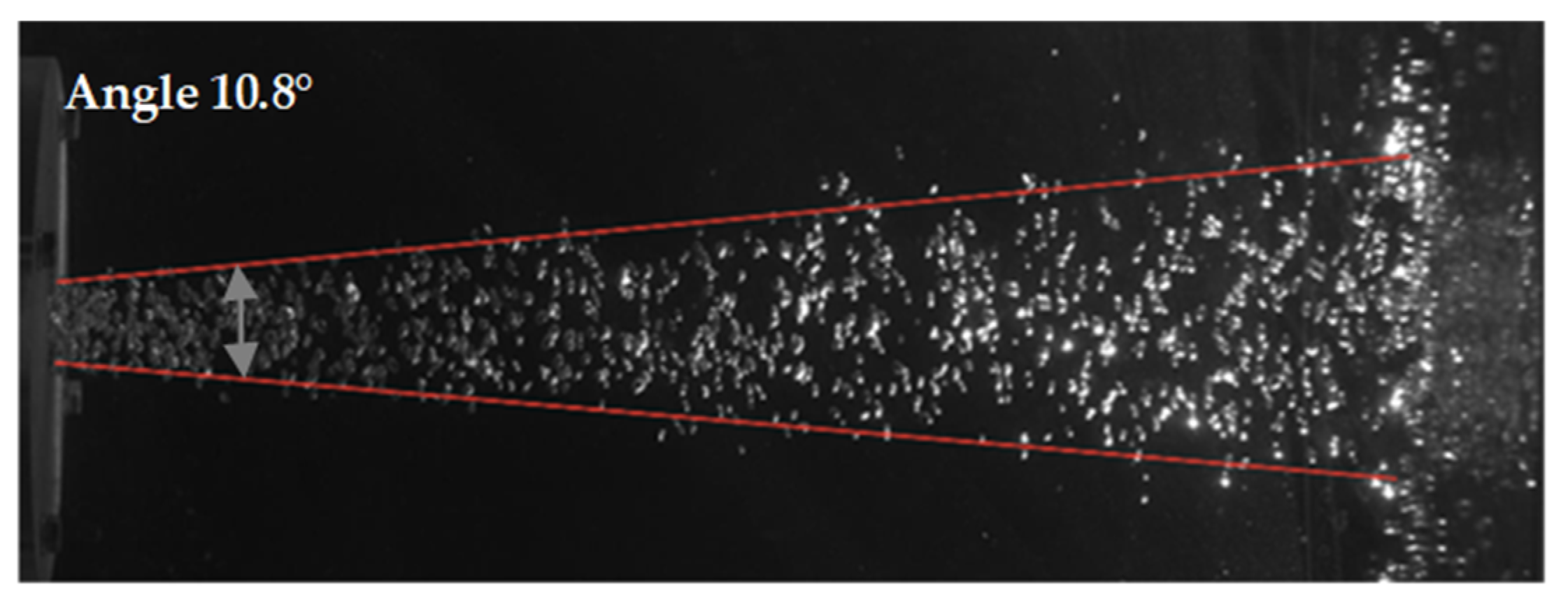
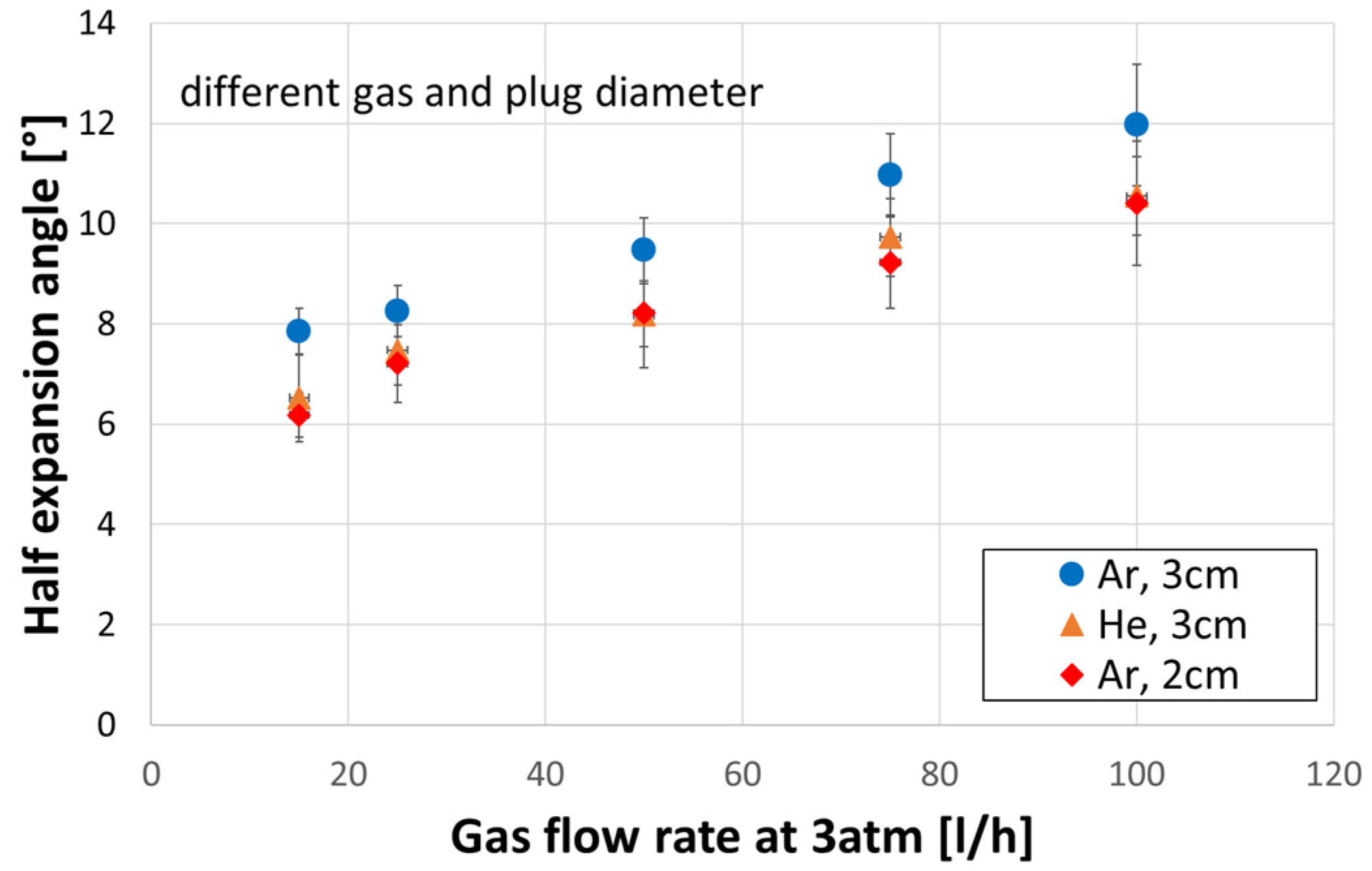
3.4. Expansion Angle
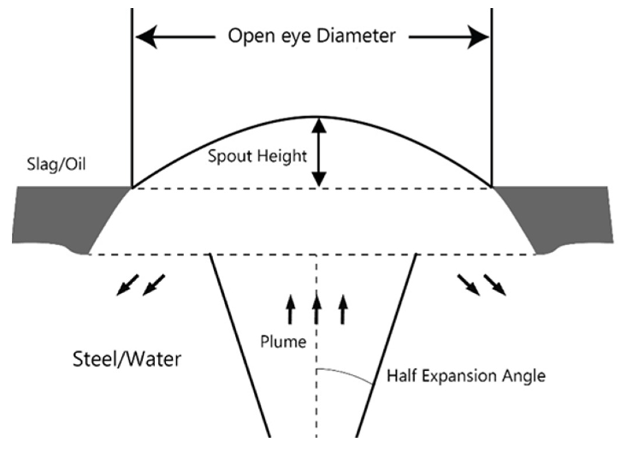
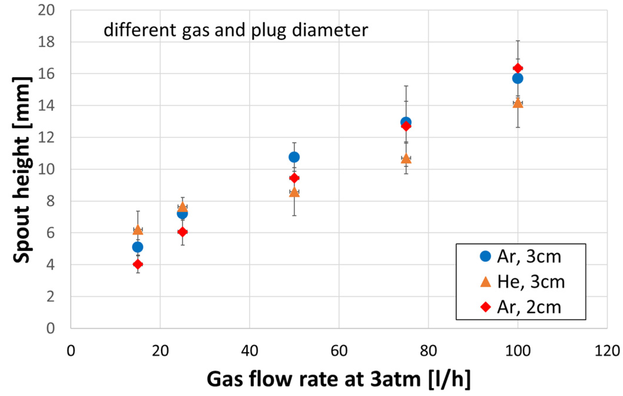
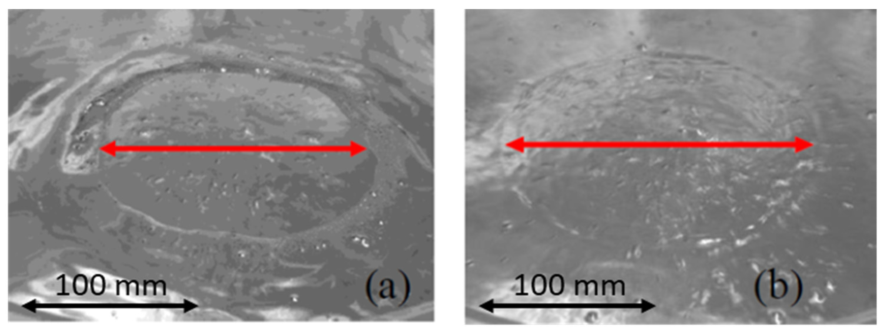
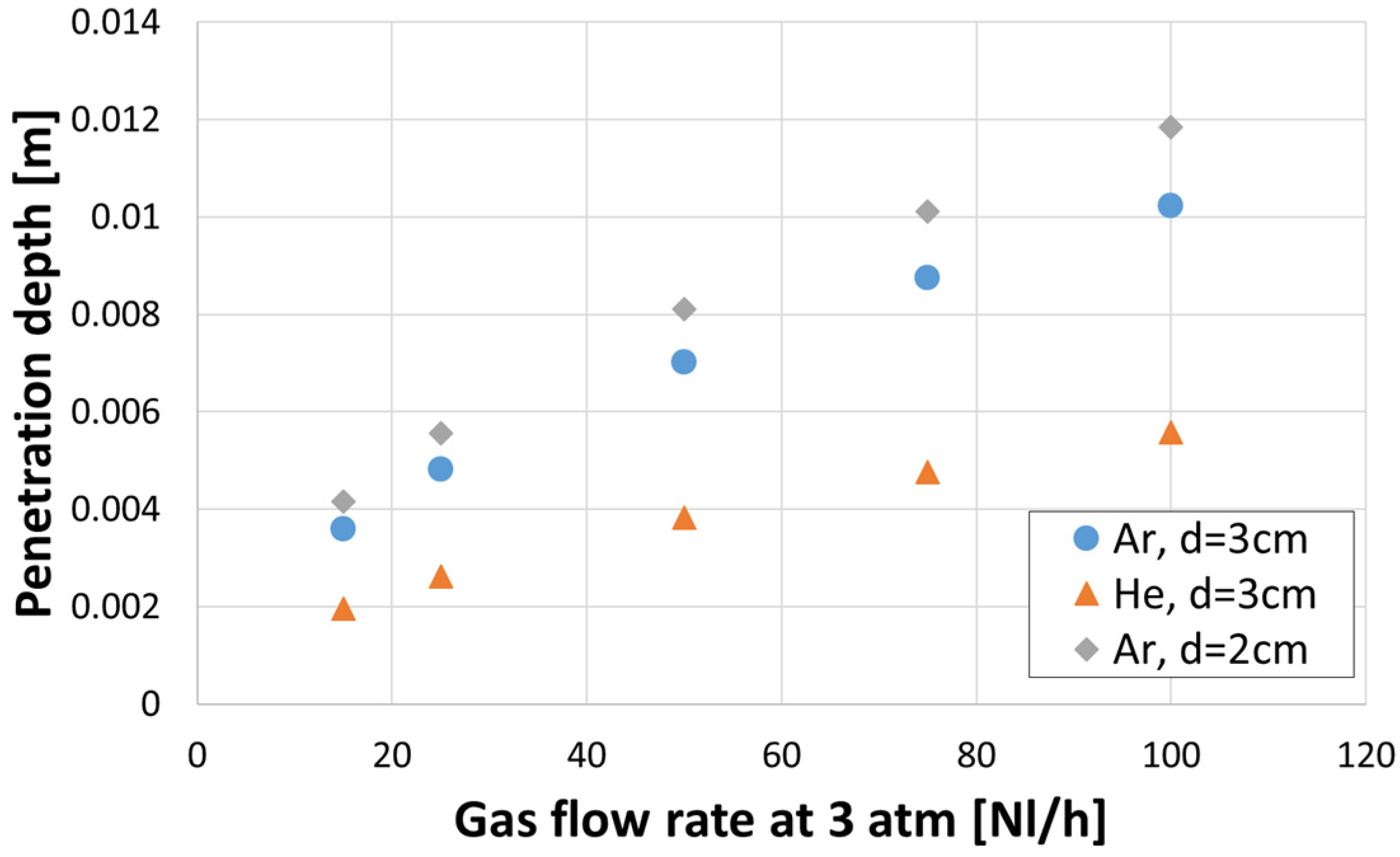
3.5. Spout Geometry
4. Discussion
5. Conclusions
- It was observed that, regardless of the gas density, an increase in a gas flow caused an increase in a bubble diameter.
- Diameter of the gas bubbles formed when helium was used was about 10% greater in comparison to argon, but only for a gas flow rate greater than 50 L/h.
- Regardless of the gas density, the diameters of bubbles were larger for the porous plug with a smaller diameter (20 mm) for the same gas flow rate. This means that in the real process, an enlargement of the plug diameter due to erosion can result in poorer mixing conditions due to lower kinetic energy of the bubbles with smaller diameters.
- Increasing the plug diameter reduced the bubble rising velocity. The helium bubble velocities were lower than those of the argon bubbles for the same gas flow rate and plug diameter.
- Axial gas hold-up in case of helium as a stirring gas was higher every time in comparison to argon for all conducted experiments.
- As the porous plug diameter decreased from 30 to 20 mm, the axial gas hold-up increased.
- Stirring with helium compared to argon caused the bubble swarm to spread at a lower angle in the liquid.
- Spout height increased with a gas flow rate. The plug diameter had a negligible influence on the spout height.
- There was no effect of the gas density on the open eye formation, unlike the plug diameter, where a smaller plug produced a smaller open eye at the surface area, which was expected and consistent with the industrial practice.
- The velocities of gas bubbles in the plume measured in this work were compared to results in the literature, which were obtained on water models using nozzles of a few millimetres size and various similarity criteria. Unfortunately, the studies utilised for comparison have not considered the gas density or nozzle diameter and provided quite variable predictions.
Author Contributions
Funding
Institutional Review Board Statement
Informed Consent Statement
Data Availability Statement
Conflicts of Interest
References
- Irons, G.A.; Guthrie, R.I.L. Bubble Formation at Nozzles in Pig Iron. Metall. Trans. B 1978, 9, 101–110. [Google Scholar] [CrossRef]
- Sahai, Y.; Guthrie, R.I.L. Hydrodynamics of Gas Stirred Melts: Part II. Axisymmetric Flows. Metall. Trans. B 1982, 13, 203–211. [Google Scholar] [CrossRef]
- Sheng, Y.Y.; Irons, G.A. Measurement and Modeling of Turbulence in the Gas/Liquid Two-Phase Zone during Gas Injection. Metall. Trans. B 1993, 24, 695–705. [Google Scholar] [CrossRef]
- Sheng, Y.Y.; Irons, G.A. The Impact of Bubble Dynamics on the Flow in Plumes of Ladle Water Models. Metall. Mater. Trans. B 1995, 26, 625–635. [Google Scholar] [CrossRef]
- Kapoor, A.; Irons, G.A. A Physical Modeling Study of Fluid-flow Phenomena in Gas-Slag Systems. ISIJ Int. 1997, 37, 829–838. [Google Scholar] [CrossRef]
- Guo, D.; Irons, G.A. Modeling of Gas-Liquid Reactions in Ladle Metallurgy: Part 1. Physical Modeling. Metall. Trans. B 2000, 31, 1447–1455. [Google Scholar] [CrossRef]
- Krishnapisharody, K.; Irons, G.A. A Study on Bath Surfaces from Gas Bubbling: Part II. Elucidation of Plume Dynamics Metall. Mater. Trans. B 2007, 38, 377–388. [Google Scholar] [CrossRef]
- Krishnapisharody, K.; Irons, G.A. Modeling of Slag Eye Formation over a Metal Bath Due to Gas Bubbling. Metall. Trans. B 2006, 37, 763–772. [Google Scholar] [CrossRef]
- Krishnapisharody, K.; Irons, G.A. A Study on Bath Surfaces from Gas Bubbling: Part I. Experimental Investigation Metall. Mater. Trans. B 2007, 38, 367–375. [Google Scholar] [CrossRef]
- Krishnapisharody, K.; Irons, G.A. A Critical Review of the Modified Froude Number in Ladle Metallurgy. Metall. Trans. B 2013, 44, 1486–1498. [Google Scholar] [CrossRef]
- Krishnapisharody, K.; Irons, G.A. A model for Slag Eyes in Steel Refining Ladles Covered with Thick Slag. Metall. Trans. B 2015, 46, 191–198. [Google Scholar] [CrossRef]
- Castillejos, A.H.; Brimacombe, J.K. Measurement of Physical Characteristics of Bubbles in Gas-Liquid Plumes: Part II. Local Properties of Turbulent Air-Water Plumes in Vertically Injected Jets. Metall. Trans. B 1987, 18, 659–671. [Google Scholar] [CrossRef]
- Catillejos, A.H.; Brimacombe, J.K. Physical Characteristics of Gas Jets Injected Vertically Upward into Liquid Metal. Metall. Trans. B 1989, 28, 595–601. [Google Scholar] [CrossRef]
- Anagbo, P.E.; Brimacombe, J.K. Plume Characteristics and Liquid Circulation in Gas Injection through a porous Plug. Metall. Trans. B 1990, 21, 637–648. [Google Scholar] [CrossRef]
- Sahajwalla, V.; Castillejos, A.H.; Brimacombe, J.K. The spout of air jets upwardly injected into a water bath. Metall. Trans. B 1990, 21, 71–80. [Google Scholar] [CrossRef]
- Zhou, M.; Brimacombe, J.K. Critical Fluid-Flow Phenomenon in a Gas-Stirred Ladle. Metall. Mater. Trans. B 1994, 25, 681–693. [Google Scholar] [CrossRef]
- Mazumdar, D. Dynamic Similarity Considerations in Gas-Stirred Ladle Systems. Metall. Trans. B 1990, 21, 925–928. [Google Scholar] [CrossRef]
- Mazumdar, D.; Kim, H.B.; Guthrie, R.I.L. Modelling criteria for flow simulation in gas stirred ladle systems: An experimental study. ISIJ Int. 2000, 27, 302–309. [Google Scholar] [CrossRef]
- Mazumdar, D. On the Estimation of Plume Rise Velocity in Gas-Stirred Ladles. Metall. Mater. Trans. B 2002, 33, 937–941. [Google Scholar] [CrossRef]
- Conejo, A.N.; Mishra, R.; Mazumdar, D. Effects of Nozzle Radial Position, Separation Angle, and Gas Flow Partitioning on the Mixing, Eye Area, and Wall Shear Stress in Ladles Fitted with Dual Plugs. Metall. Mater. Trans. B 2019, 50, 1490–1502. [Google Scholar] [CrossRef]
- Kim, S.H.; Fruehan, R.J. Physical Modeling of Liquid/Liquid Mass Transfer in Gas Stirred Ladles. Metall. Trans. B 1987, 18, 381–390. [Google Scholar] [CrossRef]
- Iguchi, M.; Takeuchi, H.; Morita, Z. The Flow Field in Air-Water Vertical Bubbling Jets in a Cylindrical Vessel. ISIJ Int. 1991, 31, 246–253. [Google Scholar] [CrossRef]
- Iguchi, M.; Nozawa, K.; Tomida, H.; Morita, Z. Bubble Characteristics in the Buoyancy Region of a Vertical Bubbling Jet. ISIJ Int. 1992, 32, 747–754. [Google Scholar] [CrossRef] [Green Version]
- Iguchi, M.; Demoto, Y.; Sugawara, N.; Morita, Z. Bubble Behavior in Hg-Air Vertical Bubbling Jets in a Cylindrical Vessel. ISIJ Int. 1992, 32, 998–1005. [Google Scholar] [CrossRef] [Green Version]
- Iguchi, M.; Kondoh, T.; Morita, Z.; Nakajima, K.; Hanazaki, K.; Uemura, T.; Yamamoto, F. Velocity and Turbulence Measurements in a Cylindrical Bath Subject to Centric Bottom Gas Injection. Metall. Mater. Trans. B 1995, 26, 241–247. [Google Scholar] [CrossRef]
- Iguchi, M.; Kawabata, H.; Nakajima, K.; Morita, Z. Measurement of Bubble Characteristics in a Molten Iron Bath at 1600 °C Using an Electroresistivity Probe. Metall. Mater. Trans. B 1995, 26, 67–74. [Google Scholar] [CrossRef]
- Iguchi, M.; Tokunaga, H. Molten Wood’s-Metal Flow in a Cylindrical Bath Agitated by Cold Bottom-Gas Injection. Metall. Mater. Trans. B 2002, 33, 695–702. [Google Scholar] [CrossRef]
- Iguchi, M.; Miyamoto, K.; Yamashita, S.; Iguchi, D.; Zeze, M. Spout Eye Area in Ladle Refining Procee. ISIJ Int. 2004, 44, 636–638. [Google Scholar] [CrossRef]
- Xie, Y.; Orsten, S.; Oeters, F. Behaviour of Bubbles at Gas Blowing into Liquid Wood’s Metal. ISIJ Int. 1992, 32, 66–75. [Google Scholar] [CrossRef] [Green Version]
- Xie, Y.; Oeters, F. Measurements of bubble plume behaviour and flow velocity in gas stirred liquid Wood’s metal with an eccentric nozzle position. Steel Res. 1994, 65, 315–319. [Google Scholar] [CrossRef]
- Tacke, K.H.; Schubert, H.G.; Weber, D.J.; Schwerdtfeger, K. Characteristics of Round Vertical Gas Bubble Jets. Metall. Trans. B 1985, 16, 263–275. [Google Scholar] [CrossRef]
- Castello-Branco, M.A.S.C.; Schwerdtfeger, K. Lagre-Scale Measurements of the Physical Characteristics of Round Vertical Bubble Plumes in Liquids. Metall. Mater. Trans. B 1994, 25, 359–371. [Google Scholar] [CrossRef]
- Castello-Branco, M.A.S.C.; Schwerdtfeger, K. Characteristics of Eccentric Bubble Plumes in Liquids. Metall. Mater. Trans. B 1996, 27, 231–239. [Google Scholar] [CrossRef]
- Yonezawa, K.; Schwerdtfeger, K. Spout Eyes Formed by a Emerging Gas Plume at the Surface of a Slag-Covered Metal Melt. Metall. Mater. Trans. B 1999, 30, 411–418. [Google Scholar] [CrossRef]
- Yonezawa, K.; Schwerdtfeger, K. Dynamics of the Spout of Gas Plumes Discharging from a Melt: Experimental Investigation with a Large-Scale Water Model. Metall. Mater. Trans. B 2000, 31, 461–468. [Google Scholar] [CrossRef]
- Ebneth, G.; Pluschkell, W. Dimensional analysis of the vertical heterogeneous buoyant plume. Steel Res. 1985, 56, 513–518. [Google Scholar] [CrossRef]
- Steinmetz, E.; Scheller, P.R. Beitrag zu den Stroemungsverhaeltnissen in einer Spuelsteinpfanne. Stahl Eisen 1881 1987, 107, 57–65. [Google Scholar]
- Kargul, T.; Falkus, J. A Hybrid Model of Steel Refining in The Ladle Furnace. Steel Res. Int. 2010, 81, 953–958. [Google Scholar] [CrossRef]
- Liu, Y.; Ersson, M.; Liu, H.; Jönsson, P.G.; Gan, Y. A Review of Physical and Numerical Approaches for the Study of Gas Stirring in Ladle Metallurgy. Metall. Mater. Trans. B 2019, 50, 555–577. [Google Scholar] [CrossRef] [Green Version]
- Pan, Y.; Guo, D.; Ma, J.; Wang, W.; Tang, F.; Li, C. Mixing Time and Fluid Flow Pattern of Composition Adjustment by Sealed Argon Bubbling with Ladles of Large Height/Diameter Ratio. ISIJ Int. 1994, 34, 794–801. [Google Scholar] [CrossRef]
- Ek, M.; Wu, L.; Valentin, P.; Sichen, D. Effect of Inert Gas Flow Rate on Homogenization and Inclusion Removal in a Gas Stirred Ladle. Steel Res. Int. 2010, 81, 1056–1063. [Google Scholar] [CrossRef]
- Smirnov, A.; Eronko, S.; Kovalenko, I.; Giessen, R. Optimization of argon-injection process parameters for ladle treatment of steel. In Proceedings of the EOSC, 5th European Oxygen Steelmaking Conference, Aachen, Germany, 26–28 July 2006; pp. 272–279. [Google Scholar]
- Krishna Murthy, G.G.; Ghosh, A.; Mehrotra, S.P. Mathematical Modeling of Mixing Phenomena in a Gas Stirred Liquid Bath. Metall. Trans. B 1989, 20, 53–59. [Google Scholar] [CrossRef]
- Krishna Murthy, G.G.; Ghosh, A.; Mehrotra, S.P. Characterization of Two-Phase Axisymmetric Plume in a Gas Stirred Liquid Bath—A Water Model Study. Metall. Trans. B 1988, 19, 885–892. [Google Scholar] [CrossRef]
- Scheller, P.; Volkova, O.; Ryabov, D. Plume Characteristics in Gas Stirred Ladles. In Jim Evans Honorary Symposium. Proceedings of the TMS Annual Meeting; Wiley: Hoboken, NJ, USA, 2010; pp. 165–172. [Google Scholar]
- Yu, S.; Zou, Z.S.; Shao, L.; Louhenkilpi, S. A Theoretical Scaling Equation for Designing Physical Modeling of Gas-Liquid Flow in Metallurgical Ladles. Steel Res. Int. 2017, 88, 1600156. [Google Scholar] [CrossRef]
- Bohl, W. Technische Strömungslehre: Stoffeigenschaften von Flüssigkeiten und Gasen, Hydrostatik, Aerostatik, Inkompressible Strömungen, Kompressible Strömungen, Strömungsmesstechnik; 11 Durchges. Aufl.; Vogel Buchverlag: Würzburg, Germany, 1978. [Google Scholar]
- Shukla, A.K.; Ryabov, D.; Volkova, O.; Scheller, P.R.; Deo, B. Cold Model Investigations of Melting of Ice in as Gas-Stirred Vessel. Metall. Mater. Trans. B 2011, 42, 224–235. [Google Scholar] [CrossRef]


| Ref. | D × H [mm] | System | Gas Inlet, d [mm] | Method | Gas Flow Rate | Results |
|---|---|---|---|---|---|---|
| Irons 1978 [1] | - | Pig iron/argon | Lance/nozzle | Acoustic device | 1–1000 [cm3/s] | Bubble frequency, bubble diameter |
| Sahai 1982 [2] | 500 × 450 | Water/air/small rectangular cards | Vertical lance, 2.16 | Video recordings | 4.3 × 10⁻⁴ [m3/s] | Velocity |
| Ebneth 1985 [36] | 1440 × 1650 | Water/air | Nozzle, 8 | Propeller flowmeter | 1.67 × 10⁻⁴, 1 × 10⁻³ [m3/s] | Plume velocity |
| Tacke 1985 [31] | 445 × 600 284 × 270 | Water/air, Hg/N2, water/He | Nozzle, 0.5–4 | EP | 59–2660 [cm3/s] | Bubble hold-up, frequency, bubble diameter |
| Kim 1987 [21] | 456 × 620 | Water/air | Nozzle: 2, 4.8 | Conductivity cell | 1–10 [L/min] | Mixing time |
| Castillejos 1987 [12] | 500 × 400, 500 × 600 | Water/air | Nozzle, 4.1, 6.35 | EP | 371, 876, 1257 [cm3/s] | Gas fraction and velocity, bubble frequency and diameter, gas velocity |
| Castillejos 1989 [13] | 210 × 210 | Hg/N2, Hg/He | Nozzle, 1.85, 4 | EP | 158–456 [cm3/s] | Gas fraction, frequency and bubble velocity, bubble diameter |
| Anagbo 1990 [14] | 500 × 400 | Water/air | Porous element, 60 | EP, LDV | 200–1200 [cm3/s] | Gas fraction, gas velocity, liquid velocity |
| Sahajwalla 1990 [15] | 500, 400 | Water/air | Nozzle, 6.35 | EP, high-speed camera | 371, 876, 1257, 1630 [cm3/s] | Spout, gas fraction, frequency, velocity of gas |
| Iguchi 1991 [22] | 126 × 400 200 × 400 | Water/air | Nozzle, 1, 2, 5 | EP, LDV | 10.3, 20.6; 41.4 [cm3/s] | Bubble frequency and gas hold-up, bubble velocity |
| Iguchi 1992 [23] | 126 × 180, 200 × 385, 390 × 385 | Water/air | Nozzle: 1, 2, 4, 5 | EP, LDV | 10–100 [cm3/s] | Bubble frequency and hold-up, bubble velocity |
| Iguchi 1992 [24] | 125 × 145 | Hg/air | Nozzle, 0.5, 1.01, 1.53 | EP | 300 [cm3/s] | Bubble hold-up, frequency, bubble velocity |
| Sheng 1993 [3] | 500 × 420 | Water/air | Nozzle | EP, LDA, camera | 50–200 [mL/s] | Gas hold-up, liquid velocity |
| Pan 1994 [40] | 280 × 280–400 | Water/N2 | Nozzle | Conductivity cell | 1.14–6 × 10⁻² [m3/h] | Mixing time |
| Zhou 1994 [16] | 500 × 200, 300, 400 | Water/air | Nozzle | EP, LDV | 2 × 10⁻⁴–20 × 10−4 [m3/s] | Critical gas flow rate |
| Castello-Branco 1994, 1996 [32,33] | 1600 × 2250 | Water/air | Nozzle | EP, propeller flowmeter | 2500, 5000, 6389, 7222, 7778 [cm3/s] | Gas hold-up, bubble frequency, liquid and gas velocities |
| Sheng 1995 [4] | 500 × 420 | Water/air | Nozzle | EP, LDA | 50–200 [mL/s] | Bubble hold-up, frequency, bubble velocity |
| Iguchi 1995 [25] | 126 × 233 | Water/air | Nozzle: 1, 2, 5 | EP, LDV | 10–160 [Ncm3/s] | Plume velocity |
| Yonezawa 1999 [34] | 290 × 225 | Hg/N2 | Nozzle | CCD camera | 0.2–0.6 [m3/h] | Spout geometry |
| Mazumdar 2000 [18] | 300 × 600, 250 × 490 | Water/Ar | Lance | Conductivity cell | 0.8–3.8 × 10⁻⁴ [m3/s] | Mixing time |
| Guo 2000 [6] | 420 × 500 | Water–NaOH/CO2 | Nozzle, 1. Plug, 10–50 | PH-probe, video | 10 [L/min] | Bubble behaviour |
| Yonezawa 2000 [35] | 1600 × 1800 | Water/air | Flush nozzle | Camera, EP | 5, 9, 18, 26, 28 [m3/h] | Spout geometry |
| Iguchi 2004 [28] | 200 × 300, 750 500 × 300, 750 | Water/silicon oil/air | Nozzle | CCD camera | - | Spout geometry |
| Krishnapi-sharody 2006, 2007, 2015 [8,9,11] | 420 × 500 | Water/air/liquid paraffin oil | Flush Nozzle, 3 | CCD camera | 1–10 [L/min] | Spout, open eye geometry |
| Ek 2010 [41] | 480 × 500 | Water/air/silicon oil/charcoal particles | Nozzle, 6 | Conductivity measurement | 0.15–0.45 [m3/h] | Mixing time, removal of non-metallic inclusion |
| Conejo 2019 [20] | 335 × 391 | Water/air–automotive oil | Nozzel, 3 | Sensor, camera | 0–7.8 [NL/min] | Mixing time, open eye area |
| Xie 1992, 1994 [29,30] | 400 × 370 | Wood/Ar, N2, He | Accentric nozzle | EP, MP | 100–1200 [cm3/s] | Bubble frequency and diameter, gas hold-up, liquid velocity |
| Iguchi 1995 [26] | 90 × 120 | Pig iron/Ar | Nozzle, 1 | EP | 50–100 [cm3/s] | Diameter, frequency and velocity of bubble |
| Iguchi 2002 [27] | 200 × 150 | Wood/He | Nozzle | EP | 60–90 [cm3/s] | Gas hold-up, bubble velocity |
| [NL/min] | Cold Water Model [L/h], 3 atm | |||||||||||
|---|---|---|---|---|---|---|---|---|---|---|---|---|
| (1) * | (2) * | (3) * | (4) * | (6) * | (7) * | (8) * | (9) * | (10) * | (11) * | (13) * | (14) * | |
| 35 | 123 | 46 | 35 | 46 | 15 | 19 | 127 | 28 | 27 | 23 | 15 | 51 |
| 60 | 211 | 79 | 59 | 79 | 25 | 33 | 218 | 48 | 47 | 40 | 25 | 87 |
| 120 | 421 | 159 | 118 | 159 | 50 | 66 | 436 | 97 | 93 | 80 | 50 | 174 |
| 180 | 632 | 238 | 177 | 238 | 75 | 100 | 653 | 145 | 140 | 120 | 76 | 261 |
| 140 | 843 | 317 | 236 | 317 | 100 | 133 | 871 | 194 | 187 | 161 | 101 | 348 |
Publisher’s Note: MDPI stays neutral with regard to jurisdictional claims in published maps and institutional affiliations. |
© 2021 by the authors. Licensee MDPI, Basel, Switzerland. This article is an open access article distributed under the terms and conditions of the Creative Commons Attribution (CC BY) license (https://creativecommons.org/licenses/by/4.0/).
Share and Cite
Riabov, D.; Gain, M.M.; Kargul, T.; Volkova, O. Influence of Gas Density and Plug Diameter on Plume Characteristics by Ladle Stirring. Crystals 2021, 11, 475. https://doi.org/10.3390/cryst11050475
Riabov D, Gain MM, Kargul T, Volkova O. Influence of Gas Density and Plug Diameter on Plume Characteristics by Ladle Stirring. Crystals. 2021; 11(5):475. https://doi.org/10.3390/cryst11050475
Chicago/Turabian StyleRiabov, Dmitrii, Muhammad Murtaza Gain, Tomasz Kargul, and Olena Volkova. 2021. "Influence of Gas Density and Plug Diameter on Plume Characteristics by Ladle Stirring" Crystals 11, no. 5: 475. https://doi.org/10.3390/cryst11050475