1. Introduction
With the development of science and technology, micromechanical mechanism plays an important role in various fields. Piezoelectric materials have the advantages of fast response speed, high energy density, and no electromagnetic interference and become the driving element or energy source of micro-mechanical mechanisms. As one of the applications of piezoelectric intelligent materials, micro-energy power generation has an important prospect in Micro Electro Mechanical Systems (MEMS) power supply [
1,
2,
3].
The principle of piezoelectric micro-energy generation is to convert the mechanical energy generated by the vibration of the piezoelectric films into electrical energy. Piezoelectric energy harvesting has the advantages of high output density, simple structure, and so on. Therefore, as an autonomous power supply system with a long or even infinite life cycle, piezoelectric energy harvester has a broad space for development in some situations where battery replacement is inconvenient and where battery replacement is desirable [
4,
5].
Numerous achievements have been made in piezoelectric energy harvesting. In general, piezoelectric generators can be divided into two kinds: cantilever beam structure and piezoelectric stack structure. The cantilever type of piezoelectric generator usually operates in the d
31 mode, while the stack type of piezoelectric generator usually operates in the d
33 mode. In terms of working principle, the cantilever type piezoelectric generator converts the mechanical energy generated by structural vibration into the electric energy generated by the elastic deformation of the piezoelectric element [
6,
7]. The piezoelectric stack type generator converts the elastic deformation of the piezoelectric stack into electrical energy, and it usually works in low-frequency mode [
8,
9].
For the cantilever beam type piezoelectric generator, it is the most widely used one. Its research achievements are also the most. Using two piezoelectric polyline beams standing with a gap distance, Pan et al. [
3] designed a hybrid energy harvester. In order to broaden the working bandwidth of the energy harvesting, the two polyline beams are coupled through the electret and electrode effect. The results show that the proposed hybrid energy harvester can generate an output power of 69.1 μW. To monitor the random vibration of the rail, an efficient rail-borne piezoelectric energy harvester is used to collect energy from the random railway vibration [
10]. Its output power peaks at the first two resonance frequencies are 1036.9 and 8.01 mW/Hz. Besides, a while-drilling energy harvesting device is proposed as a continuous power supply for downhole instruments during the drilling procedure [
11]. The designed device can obtain the best energy harvest performance with a peak voltage of 15–40 V with the thickness of the piezoelectric patches of 1.2–1.4 mm. Kan et al. [
12] developed a piezoelectric energy harvester excited by an axially pushed wedge cam. The proposed rotary energy harvester is characterized by the simultaneous realization of unidirectional deformation and limited amplitude for piezoelectric vibrators. Under the optimum matching parameters, a maximum power of 10.88 mW can be obtained. In order to obtain the maximum power output of the energy harvesting system, Koszewnik et al. [
13] designed a kind of mechanical and electrical impedance matching model and discussed the mechanical aspects of using weight as the way to tune the piezoelectric beam to a specific frequency. Using a laboratory stand equipped with a vibration generator, a piezoelectric energy harvester, and acceleration sensors, the correctness of the theoretical model is verified.
Stack type piezoelectric generator can produce more energy because of their high energy density. Peng et al. [
14] propose a stack type compressive mode piezoelectric generator and study the influence of frequency-up conversion effect on the generator. The frequency-up conversion effect is induced by amplitude truncations of the mass under external excitation. The experimental results show that a millimeter-size generator can output an instantaneous peak power of 0.32 W. Wen et al. [
15] designed a piezoelectric generator with integrated multistage force amplification. Experimental results show that the harvester exhibits a high-peak power output of 50.8 mW across a matched resistor. What is more, in order to gather the vibration energy of pressure fluctuations in the pipeline system, a piezoelectric stack energy harvester is designed by Cao et al. [
16]. The results show that it is great potential to realize a self-powered wireless sensor network technology for pipeline monitoring.
Various kinds of cantilever type and stack type piezoelectric generators have been designed and manufactured. However, when the amplitude is weak, how to collect the energy of vibration is a problem to be solved. In order to overcome the above problem, a micro-power generator based on two piezoelectric MFC films is proposed. The proposed generator can realize the energy harvesting of small vibrations. At the same time, due to the use of a pair of MFC piezoelectric films acting on the upper and lower sides of the flexure strip, each vibration movement can achieve double energy collection. Therefore, the piezoelectric generator proposed in this paper can achieve a larger energy density.
In this paper, the operating principle of the micro-power generator is illustrated. The design process of the structure is given. Meanwhile, an experimental platform is built to test the output characteristics of the micro-power generator.
2. Design
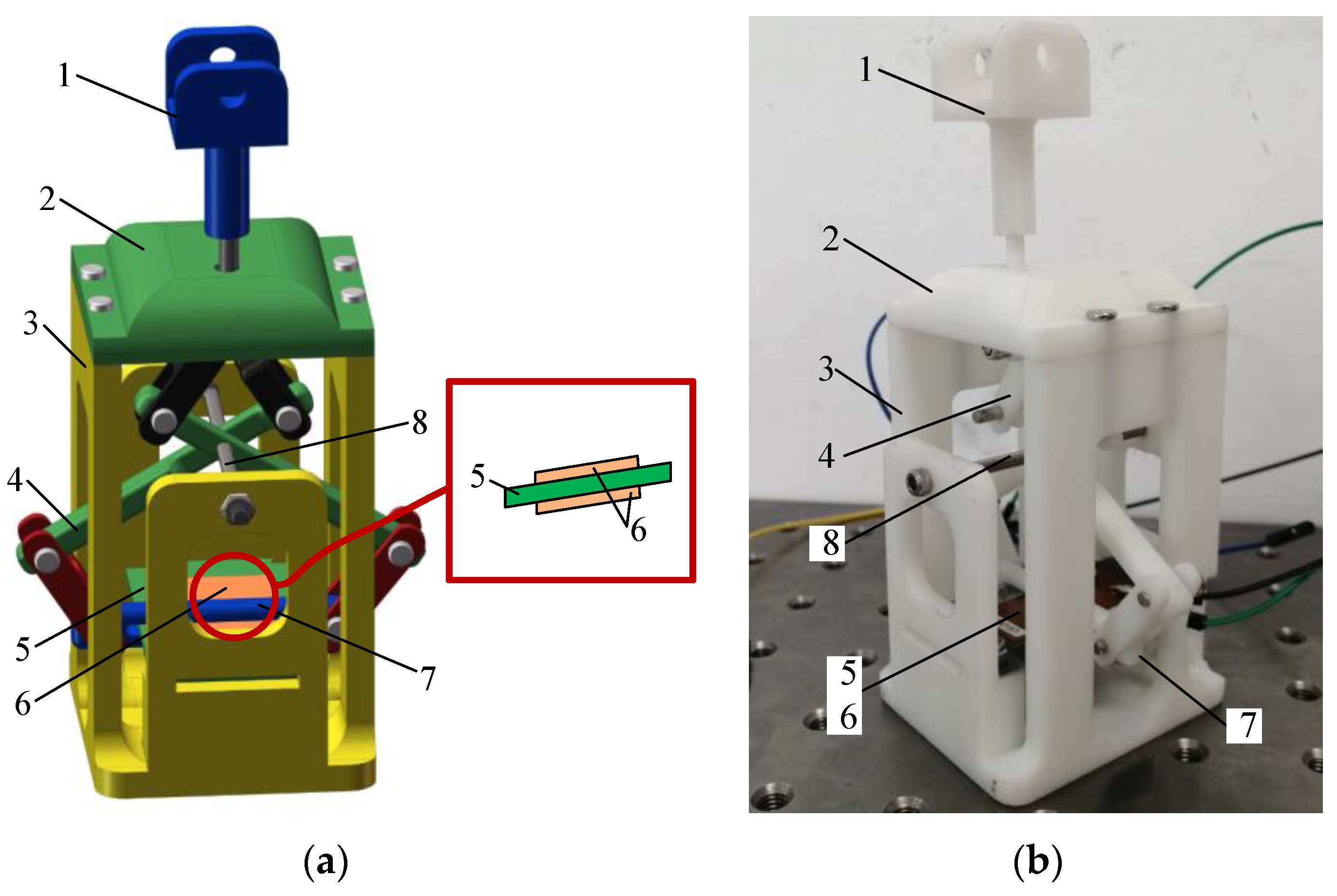
The proposed micro-power piezoelectric generator is shown in
Figure 1. It consists of telescoping rod (1), cover (2), body case (3), displacement amplifying mechanism (4), flexure strip (5), piezoelectric MFC films (6), position-limit mechanism (7), and fixed pin (8). Among them, the power generation unit composed of flexure strip and piezoelectric MFC film is the core of the piezoelectric generator. Performance parameters of MFC piezoelectric film are shown in
Table 1. Two MFC piezoelectric films distribute on the upper and lower sides of the flexure strip. One end of the flexure strip is fixed, and the other end is free. The working principle of the power generation unit is to achieve bending deformation through the reciprocating motion of the MFC piezoelectric films and then output voltage.
The function of the displacement amplification mechanism is to amplify the vibration amplitude and increase the effectiveness of energy collection. Herein, the lever principle is used to amplify the vibration displacement.
For a machined prototype, there will be clearance between the assembly parts. When the clearance value is within a certain range, it has little effect on the output performance of the piezoelectric generator. When the clearance between parts of the assembly is too large, the clearance can be reduced by adding a gasket. When the clearance between the shaft and the hole is too large, a metal film can be pasted on the shaft to reduce the clearance.
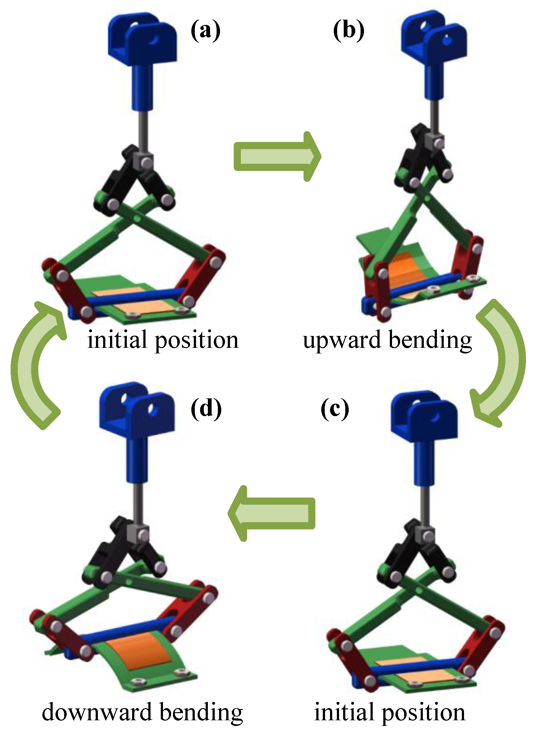
Figure 2 presents the working principle of the micro-power piezoelectric generator. For one motion period, the generating unit can achieve upward bending and downward bending movements. The excitation signal applied to the telescopic rod is a triangular wave signal, as shown in
Figure 3, where
δm is its amplitude. The detailed operation steps are as follows:
Step 1: In the initial state, the flexure strip and the two piezoelectric MFC films have no deformation and are at the original length. At the same time, the displacement amplification mechanism has no stretching change.
Step 2: When the time is at the period of T/4, the telescopic rod moves to the top position, and its amplitude comes up to δm. The displacement amplification mechanism is elongated. At this point, the limiting mechanism moves down to the lowest end. Driven by the limiting mechanism, the flexure strip with piezoelectric MFC films is bent upward and deformed.
Step 3: When the time passes T/4, the telescopic rod begins to fall back. The displacement amplification mechanism is gradually restored to the initial position. At the same time, the bending degree of the flexure strip and the piezoelectric MFC films decreases. When the time reaches T/2, the power generation unit and displacement amplification mechanism revert to the initial position.
Step 4: When time t is greater than T/2, the excitation amplitude increases in reverse, and the amplifying mechanism is compressed, and the flexure strip and the piezoelectric MFC films begin to bend downward. When the time reaches 3T/4, the amplitude of the telescopic rod is −δm, and the compression degree of the displacement amplification mechanism reaches the maximum. At the same time, the flexure strip and the piezoelectric MFC films reach the maximum bending state.
Step 5: As time goes past 3T/4 of the period, the deformation degree of the flexure strip and the piezoelectric MFC films decreases gradually. At the same time, the displacement amplifying mechanism and the telescopic rod is gradually restored to their original state. When the time reaches period T, the flexure strip and the piezoelectric MFC films are restored to their original state.
In one cycle, the two piezoelectric MFC films complete an upward bending deformation and a downward bending deformation, thus more electricity can be generated during one motion cycle. Under the action of a continuous excitation signal, the micro-power piezoelectric generator can output continuous voltage.
In order to observe the deformation of the piezoelectric MFC films and the flexure strip under external excitation, the finite element analysis (FEA) of the proposed piezoelectric generator with ANSYS software was carried out.
Figure 4 shows the process and results of FEA for the generator, where
Figure 4a is the meshing model, while
Figure 4b presents the deformation results of the generator under excitation displacement of 2 mm. The free meshing method was used to meshing the structural model with a mesh size of 0.5 mm. After meshing, a total of 152,800 nodes and 619,371 meshes were obtained. Then, displacement loads are applied to the telescoping rod of the piezoelectric generator. Here, the magnitude of displacement load is 2–10 mm respectively. Finally, the statics were solved, and the deformation results can be observed. By changing the magnitude of the applied displacement load, the deformation displacement of the flexure strip can be obtained, as shown in
Table 2.
The results show that the deformation of the flexure strip is more than twice that of the input excitation displacement. With the increase of displacement load, the deformation displacement increases.
Besides, the analysis shows that the amplification mechanism amplifies the excitation displacement. The deformation is mainly concentrated in the flexure strip, while the deformation of other parts is very small. Thus, the parts manufactured by PLA materials with 3D printing technology can meet the requirements.
Furthermore, the deformation of the structure under different excitation frequencies is analyzed by FEA. Results show that the excitation frequency has almost no effect on the deformation of the structure.
The proposed piezoelectric generator is excited by the reciprocating motion of the telescoping rod. Therefore, the time expression of the reciprocating motion of the telescopic rod approximates the triangular wave. Its expression can be rewritten as
where
em is the amplitude of the excitation signal,
f is the frequency of the excitation signal.
When the deformation of the piezoelectric MFC film is
δp, the output current of the load for the piezoelectric generator is
where
d31 is piezoelectric strain constant,
E is Young’s modulus of MFC film,
Sp is the surface area of the piezoelectric material,
lp is the length of piezoelectric MFC film.
The output power of the proposed piezoelectric generator is
where
C is the capacitance of piezoelectric MFC.
The output voltage the generator is
3. Experimental Analysis
Two piezoelectric MFC films with an effective size of 28 mm × 14 mm × 0.3 mm were used to assemble the micro-power piezoelectric generator, and piezoelectric MFC film 1 and film 2 were pasted on the lower and upper parts of the flexure strip, respectively. The thickness of the piezoelectric MFC film and the flexure strip are 0.3 mm and 0.2 mm, respectively. The flexure strip was a rectangular structure, and its performance parameters are shown in
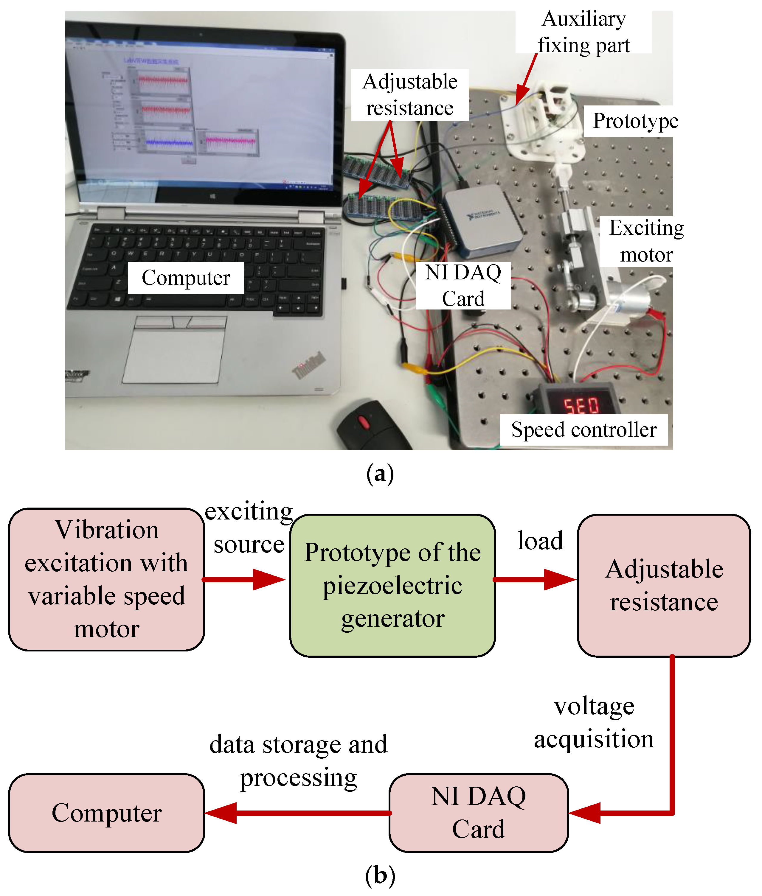
Table 3. The overall structure of the generator was processed by a 3D printing process with PLA material. An experimental platform was built to test the output performance of the proposed micro-power piezoelectric generator. The experimental test system is shown in
Figure 5. The vibration excitation of the piezoelectric generator was realized by the reciprocating motion of a DC motor. Moreover, the excitation frequency can be changed with a speed controller. In order to increase the output energy, the amplitude of the excitation signal was set to 6 mm. To test the output characteristics of the micro-power generator, two adjustable resistors varied in the range of 0–10 MΩ were used as load resistor. Besides, a NI USB-6002 data acquisition (DAQ) card was used to collect the output voltage of the piezoelectric generator. The computer installed with LabVIEW acquisition software was used to obtain the test data.
The output characteristic test of the piezoelectric generator mainly included the output voltage test under transient excitation and continuous excitation. The output power can be calculated according to the output voltage value and load resistance value. The test steps were as follows:
Step 1: Transient excitation can be achieved by pushing and pulling the telescopic rod. By changing the load resistance from 10 kΩ to 40 kΩ, the transient peak voltage of the two piezoelectric MFC films under different loads can be collected, respectively.
Step 2: Then, the experiment of output characteristics under continuous excitation is carried out. First, set the resistance of the two adjustable resistors to 10 kΩ and keep them constant.
Step 3: Connect the power to the motor, and then adjust the motor speed from 10 Hz to 26 Hz through the speed controller. At each constant frequency, the output voltage of the two piezoelectric MFC films of the piezoelectric generator is tested.
Step 4: After completing all tests at a constant load resistance value, change the load resistance value from 10 kΩ to 50 kΩ and repeat step 3 for the output voltage measurement of the micro-power generator.
The output voltage values under transient excitation can be obtained through step 1, while those of the micro-power generator under continuous excitation can be collected through steps 2 to 4.
According to the above analysis, the reason for selecting 10–50 kΩ as the load resistance variation range is that when the load resistance increased to 50 kΩ, the output voltage of the micro-power piezoelectric generator reached its maximum value, and it was meaningless to expand the research range further. In addition, the range of 10–50 kΩ was sufficient to summarize the variation rule of the output voltage and output power of the micro-power piezoelectric generator.
The focus of this paper was to design a micro-power piezoelectric generator and verify the feasibility of the designed scheme with an experimental platform. Therefore, energy conversion circuits were not involved in this study, and the output voltage acquisition and testing were carried out through the NI 6002 DAQ card. This paper focused more on the output voltage and power of the proposed micro-power piezoelectric generator and did not calculate and test the impedance of the system.
Firstly, the output characteristic of the micro-power piezoelectric generator under transient excitation was tested.
Figure 6 shows the test results of output voltage under transient excitation, where
Ut1 and
Ut2 represented the output voltages of piezoelectric MFC films 1 and 2.
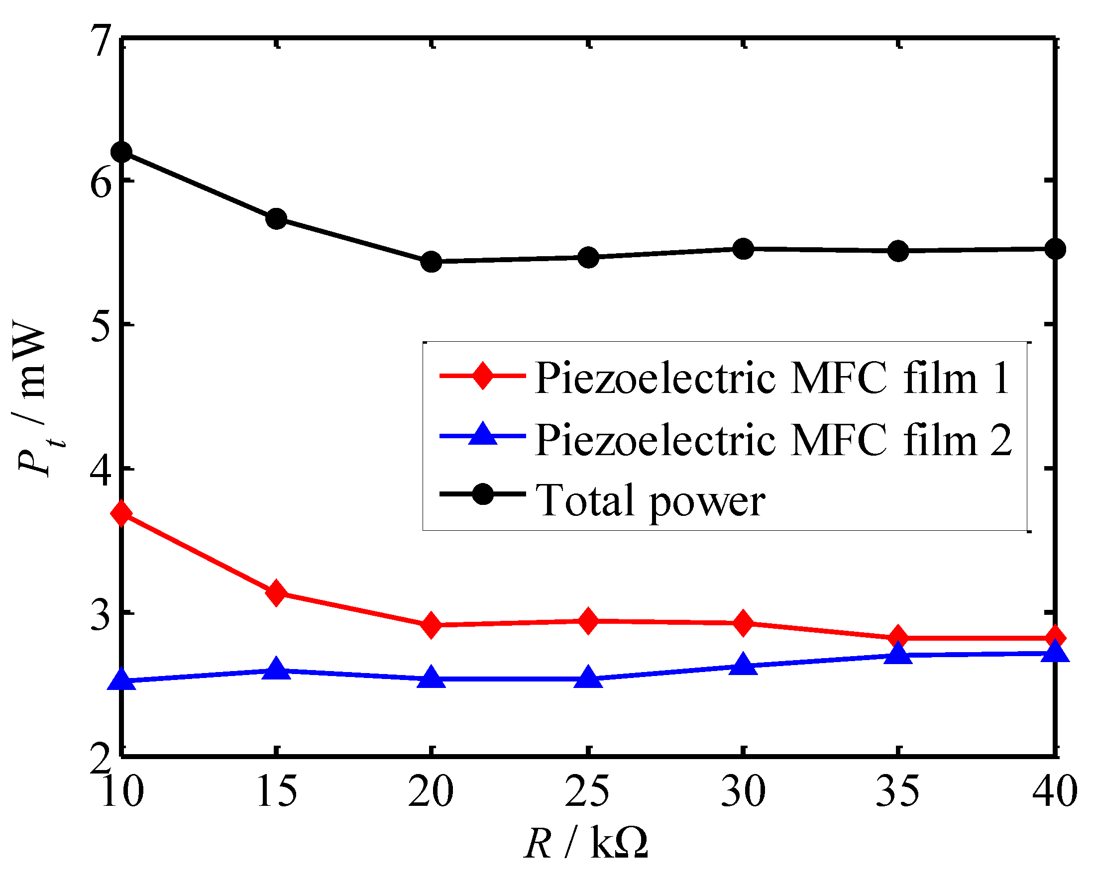
Figure 7 and
Figure 8 present the output voltage and power vary with load resistance under transient excitation. Here, the output voltage and output power of the two piezoelectric MFCs were collected, respectively, and then the total power was obtained by calculating the output power of the two directions. The reason for the calculation of total power is that the deformations of the two piezoelectric MFC films under outer excitation were consistent, and the generated voltage was basically synchronous, thus the total power was obtained by calculating the sum of the power of the two piezoelectric MFC films. Although there will be a small error through calculation, it can basically calculate the total power. The output voltage and power under continuous excitation were also obtained by the above method.
(1) Under transient excitation, the output voltages of the micro-power piezoelectric generator are instantaneous. The voltage responses of the two piezoelectric MFC films are generated at the same time under transient excitation, and the amplitudes of the voltage response are slightly different.
(2) As the load resistance increases, the output voltages of the micro-power piezoelectric generator increase. The output voltage of piezoelectric MFC film 1 pasted on the lower surface of the flexible strip is slightly higher than that of piezoelectric MFC film 2 on the upper surface.
(3) The power change of the piezoelectric generator is relatively stable under instantaneous excitation. The stability of output power of piezoelectric MFC film 2 is higher than that of piezoelectric MFC film 1. The maximum total power occurs at a load of 10 kΩ, which is 6.2 mW.
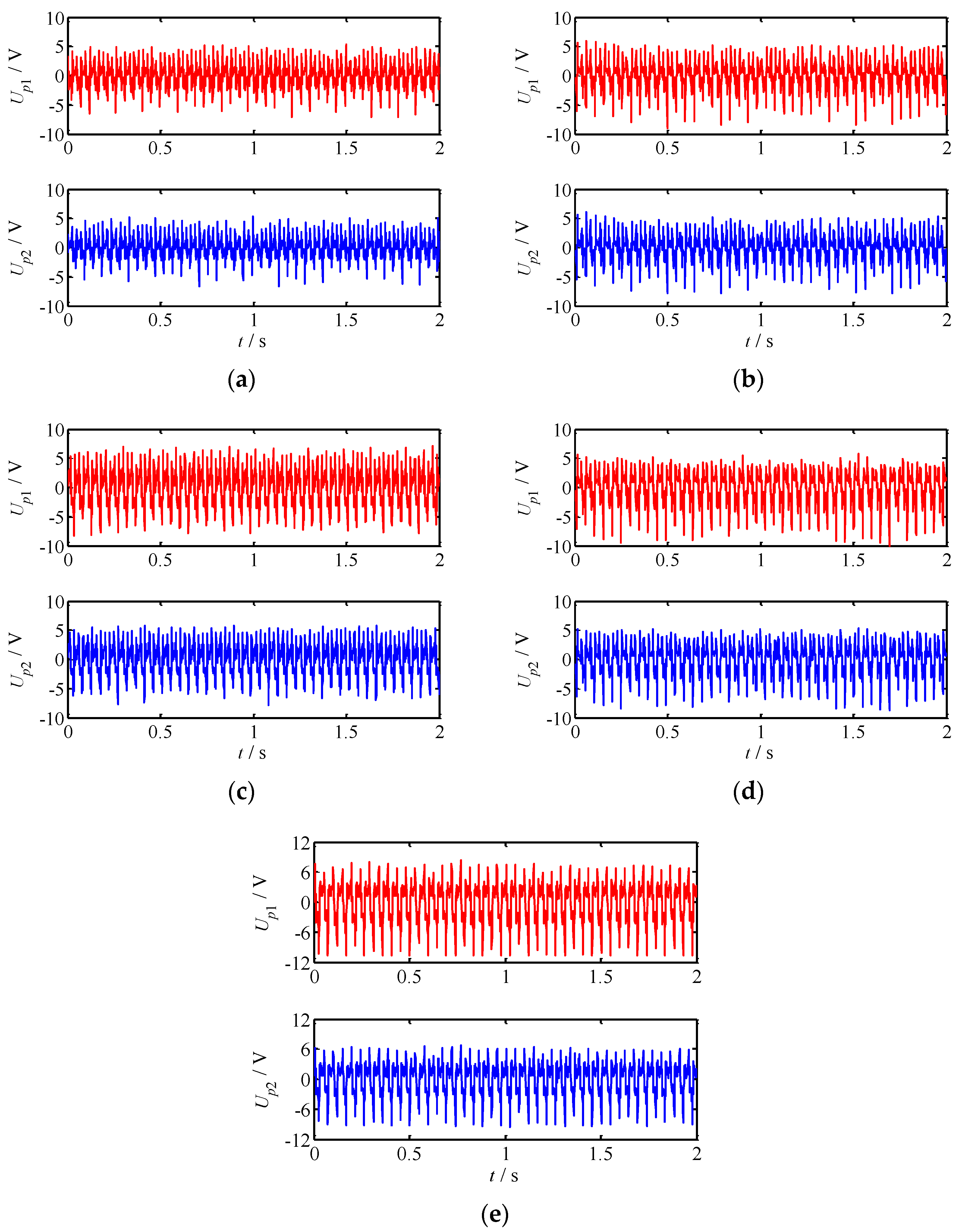
In addition, the output characteristics of the proposed micro-power piezoelectric generator under continuous excitation were studied. The variation law of the output voltage of the two piezoelectric MFC films with time was obtained under constant excitation frequency, which is shown in
Figure 9. Here, a frequency 26 Hz was selected as the excitation frequency. From the output voltage variation law, it can be obtained:
When the load resistance was constant, the peak values of the output voltage of the two piezoelectric MFC films were close at the same exciting frequency. When the excitation frequency was constant, the peak voltage increased with the increase of load resistance.
It can be seen from the output results that the output voltage changes were relatively stable under continuous excitation with constant excitation frequency.
The variation of output voltage with excitation frequency and load resistance was also studied. Here, the frequency range of 10–26 Hz and the resistance range of 10–50 kΩ were selected for studying. There were two reasons for choosing a frequency range of 10 Hz to 26 Hz. One reason was that the proposed micro-power generator was designed to generate electricity by picking up low-frequency vibrations. Moreover, the low frequency range was not a resonant frequency. Another reason for choosing this frequency band was that the maximum operating frequency range of the exciting motor was 26 Hz. Although the selected frequency range was narrow, it was sufficient for the study of the output performance of the piezoelectric generator in this paper.
The results of output voltage are shown in
Figure 10 and
Figure 11. In order to observe the difference of the output voltage of the two piezoelectric MFC films, the output error of the two piezoelectric plates was solved, which is shown in
Table 4. From the figures and table, it can be obtained:
(1) When the load resistance is constant, the output voltage of the two piezoelectric MFC films of the proposed micro-power generator increases non-linearly with the increase of the excitation frequency. The larger the resistance is, the more significant the nonlinear variation of voltage with frequency is.
(2) With the increase of exciting frequency, the output voltage of the two piezoelectric MFC films changes in the same law, and the voltage values at a certain frequency are close. The maximum error in both MFC films occurs when the load resistance of 50 kΩ and the excitation frequency of 10 Hz, and the maximum error is 12.4%. While the minimum error is 0.8%, which occurs at R = 10 kΩ and f = 10 Hz. The error is large when the excitation frequency is very low or high, the reason is that the vibration of the MFC films is unstable when the frequency is very low, and the energy loss is large when the frequency is high. Therefore, in order to reduce the error, the excitation frequency and load resistance should be as moderate as possible.
(3) The output voltage of piezoelectric MFC film 1 is slightly greater than that of piezoelectric MFC film 2. There are many reasons for the output error of the two piezoelectric MFC films. On the one hand, the output performance of the piezoelectric MFC films is different; on the other hand, the deviation of the paste position and the force position of the piezoelectric MFC films results in the output error.
(4) When the exciting frequency is constant, the output voltage increases non-linearly with the increase of load resistance. The larger the load resistance is, the smaller the changing rate of output voltage is.
In conclusion, the output voltage of the piezoelectric generator varies in direct proportion to the excitation frequency and the load resistance. Under the same external conditions, the peak values of the output voltage of the two piezoelectric MFC films are close to each other.
The output power is the most important parameter of the output performance for the generator. Therefore, the output power of the piezoelectric generator was analyzed in this paper.
Figure 12 and
Figure 13 show the variation of output power with excitation frequency and load resistance, respectively, where the total power is the sum of the output power of the two piezoelectric MFC films. In order to better show the power variation trend, the total power varied with the load resistance, which varied from 2 kΩ to 50 kΩ and was investigated (see
Figure 14). In
Figure 12,
Figure 13 and
Figure 14, the total power under continuous excitation was obtained by calculating the output power of the two directions. From
Figure 12,
Figure 13 and
Figure 14, it is known that:
- (1)
When the load resistance is constant, the output power of the proposed micro-power piezoelectric generator increases non-linearly with the increase of the excitation frequency. Moreover, the output power generated by the two piezoelectric MFC films is very close.
- (2)
When the load resistance is different, the variation law of output power with excitation frequency is the same, and the difference is that the maximum value of output power changes.
- (3)
The variation of the total power with excitation frequency is the same as that of the output power of a single piezoelectric MFC film with excitation frequency. The maximum total power occurs when the load resistance is 10 kΩ, and the excitation frequency is 26 Hz, with a maximum of 11.9 mW.
- (4)
When the excitation frequency is constant, the output power decreases first and then becomes stable with the increase of load resistance. When the load resistance is small, the output power is relatively large. Moreover, the changing rate of the output power with load resistance increases with the increase of excitation frequency.
- (5)
The output power of the piezoelectric generator proposed in this paper is not stable. On the one hand, the reason lies in the errors in the manufacture and assembly of parts. On the other hand, the vibration of the micro-power piezoelectric generator itself affects the output precision when the external excitation is applied to the generator.
In order to improve the stability of the output power of piezoelectric generator, two measures can be taken. Firstly, the machining quality and assembly precision of the prototype should be improved. Precision machine tools can be used to help improve the machining accuracy of parts. Secondly, the influence of external vibration on the work of the prototype should be reduced, especially to avoid the resonance of the prototype. For the above two methods, the first method is easier to realize, but the influence of vibration on the output characteristics of the prototype is more difficult to eliminate.
By comparing the output voltage and output power under continuous excitation and transient excitation, it can be seen that the output voltage under transient excitation was instantaneous, while the output voltage under continuous excitation changed continuously with time. The output power changed slightly with the load resistance under the transient excitation, while the output power changed greatly with the load under the continuous excitation. The reason is that the energy under transient excitation is limited, and when the excitation amplitude is appropriate, the maximum output energy can be reached. In the case of continuous excitation, the output of energy is continuous. Under different loads, the energy loss is also different, and the power obtained is also different.
Therefore, the research in this paper is applicable to power generation under any continuous excitation and transient excitation and has a certain reference value.


