Article

Feasibility Study of an Iron-Based Composite Added with Al2O3/ZrO2 as an Oxygen Carrier in the Chemical Looping Applications

Green Energy and Environment Research Laboratories, Industrial Technology Research Institute (ITRI) 360, Gaofa 2nd Rd., Guiren Dist., Tainan City 711010, Taiwan
*
Author to whom correspondence should be addressed.
Crystals 2021, 11(8), 971; https://doi.org/10.3390/cryst11080971
Submission received: 15 July 2021 / Revised: 13 August 2021 / Accepted: 14 August 2021 / Published: 17 August 2021

Abstract

:
The chemical looping process is a promising approach for carbon capture. Oxygen carriers play the crucial role of carrying oxygen between oxidation and reduction reactors. In this study, iron-based composites, added with alumina and zirconia, were used as the oxygen carriers. The feasibility study of these composites for chemical looping applications was then evaluated by measuring their properties, including mechanical properties, relative density, microstructures, crystal structure, and their capacity of oxygen. The results suggest that the addition of zirconia led the decrease of the bulk relative density and thus had a negative effect to both crush strength and attrition. Crush strength declined from 57 kgf to 26 kgf when using zirconia, replacing alumina, in an iron-based composite as the inner material. In addition, the phases in oxidizing and reducing reaction were also revealed. The formation of the spinel phase (FeAl2O4) was the major factor that altered the capacity of oxygen. It inhibited Fe2O3’s ability to be completely reduced to Fe and thus decrease the capacity of oxygen. The value was therefore decreased from 9.7% to 6.2% after 50 redox cycles in alumina addition composite. On the other hand, for the zirconia addition, all of the Fe2O3 could transform to Fe, which provided 8.5% of oxygen capacity after 50 redox cycles. A dense layer which was identified as the Fe2O3 in the bulk surface was observed in the samples reacted with 50 redox cycles. The proposed mechanism of the formation of Fe2O3 layer and its corresponding kinetic analysis was also revealed in this study.

1. Introduction

1.1. Background for Carbon Reduction

Most developed countries have been focusing on carbon-reducing technologies for many years to achieve carbon neutrality by 2050. Carbon capture and storage is the most promising approach to achieve this objective [1].
Between 2010 and 2018, more than 70% of the power generated in Taiwan involved fossil fuels. Moreover, nearly 90,000 kt CO2 is emitted every year [2]. According to statistics released by the International Energy Agency in 2018, global CO2 emissions totaled 4.42 t CO2; those of Taiwan were 10.83 t CO2 per capita—twice the global average [3]. Therefore, lowering CO2 emissions in Taiwan is imperative.

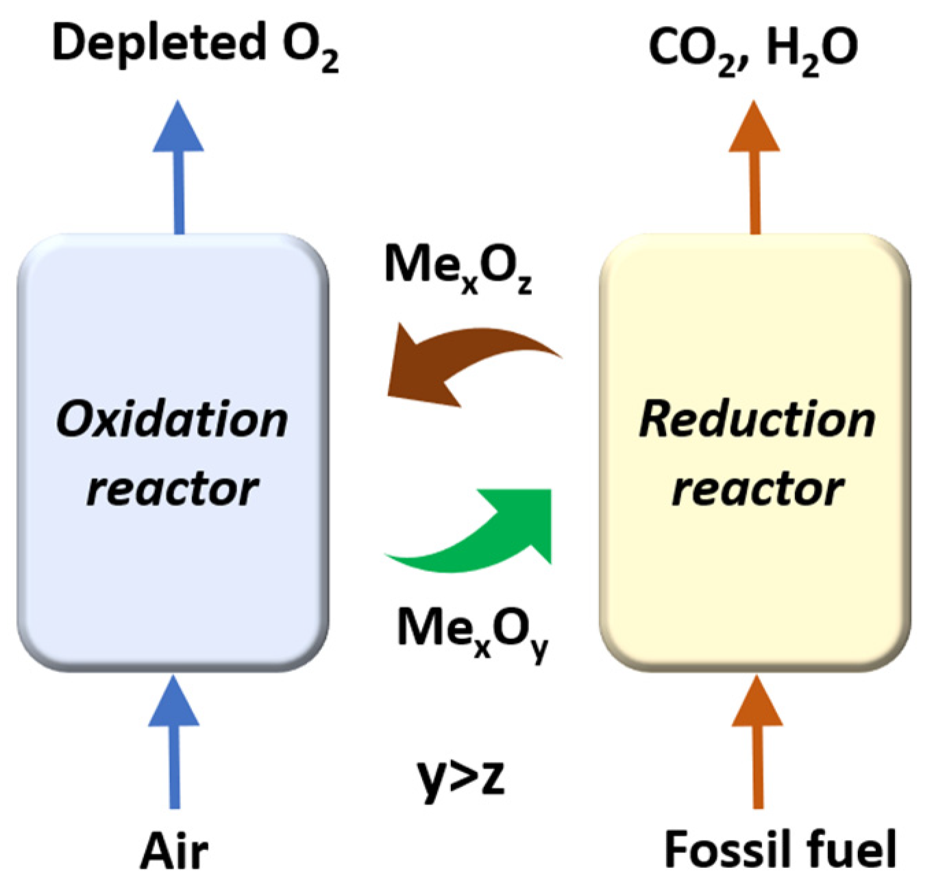
1.2. Chemical Looping Process (CLP)

The chemical looping process is a highly promising method for reducing CO2 emissions because of its inherent gas separation property. It also does not require additional facilities to separate CO2 from flue gas. The schematic of chemical looping is displayed in Figure 1. In the chemical looping process, metal oxide (MexOy), usually used as the oxygen carrier, passes through the reduction reactor and reacts with fuel, such as coal, natural gas, biomass, and so on. High-purity CO2 is then produced and can be used directly or stored. The oxygen-depleted particle (MexOz, y > z) can circulate to the oxidation reactor and reacts with air; subsequently, oxygen within the oxygen carrier can be recovered again. Some further applications have been proposed by using this concept.

1.2.1. Chemical Looping Combustion (CLC)

Instead of air, the oxygen contained by the oxygen carrier is applied to combust with fuel in the chemical looping combustion process. Nitrogen can be avoided through this combustion process. For example, only CO2 is produced from a reducer with the use of coal as the fuel, which is illustrated in Figure 2. The exhaust gas (usually composed with N2 and low concentration of O2) from the oxidation reactor will have a high temperature which could be introduced to a gas turbine to produce electricity [4]. The heat value is altered by the composition of the fuel and the material of the oxygen carrier. While all of the combustion reactions are exothermic reactions, the reaction between the fuel and oxygen carrier could be endothermic or exothermic [5]. In most cases, the oxygen carrier should also act as the heat carrier which can conduct the heat from the oxidation reactor to provide to heat to the reduction reactor.

1.2.2. Chemical Looping Oxygen Uncoupling (CLOU)

Since the oxygen carriers are usually solid, the reaction rate with the use of gaseous or liquid fuel such as natural gas is still acceptable for the particle use. However, in the case of the solid fuel such as coal, the reaction only happens in the interface of solid to solid, which leads to a slow reaction rate. Chemical looping oxygen uncoupling (CLOU) was therefore proposed for improving this problem. Chemical looping oxygen uncoupling was first proposed by Lyngfelt and Mattiso in 2009 [6]. The differences between CLC and CLOU are mainly in the material of the metal oxide (usually are Cu or Ni). By manipulating the temperature and oxygen partial pressure, the oxygen can release from the oxygen carrier spontaneously. The solid fuel can not only react with the oxygen carrier but also with gaseous oxygen, which is illustrated in Figure 2. The reaction rate of the CLOU was almost 50 times faster than that in the CLC [7].

1.2.3. Chemical Looping Air Separation (CLAS)

Chemical looping air separation (CLAS) is a further application from chemical looping oxygen uncoupling (CLOU), presented in Figure 2. By introducing the inner gas or vacuuming the reduction reactor, the oxygen partial pressure can be reduced. Pure oxygen can be released and collected from the oxygen carrier subsequently [8].
Compared to the conventional methods for oxygen production such as cryogenic air separation (CAS) and pressure swing adsorption (PSA), CLAS has the specifications of a lower energy penalty and higher outlet temperature [9]. According to the simulation results revealed from Newcastle University, the oxygen produced by the CLAS applied to combustion can only have one-tenth in the energy consumption than that of the CAS [10,11]. In addition, integrating the CLAS process and Oxy-fuel combustion or solid oxide fuel cell was also a novel application. With the use of higher-temperature oxygen produced from CLAS, it can avoid the gas preheating process, which can reduce the energy consumption.

1.2.4. Syngas Chemical Looping (SCL) and Chemical Looping Hydrogen Generation (CLHG)

Through controlling the oxidation state of the metal oxide and the oxygen pressure, the composition of exhaust gas can be manipulated. For the syngas chemical looping process (SCL), CO2, syngas (CO + H2) can be obtained from the reduction reactor by the incomplete reaction between the fossil fuel and oxygen carrier [12]. This process can further combine with the integrated gasification combined cycle (IGCC), which might provide higher thermal efficiency [13].
Chemical looping hydrogen generation (CLHG) is another potential application of the chemical looping process. The oxygen carrier developed in this study tends to be applied in the CLHG process. An additional reactor, which is called a steam reactor, is needed for hydrogen generation. The steam reactor is usually set up after the reduction process and before the oxidation process [14]. Compared to other chemical looping applications, metal oxide using in the CLHG should be deeply reduced, which can provide higher reactivity for hydrogen generation. Taking iron-based oxygen carriers as an example, iron (Fe) can be oxidized by steam to be wüstite (FeO) or magnetite (Fe3O4). Hydrogen can be produced through Equation (1) and Equation (2). Afterwards, the reduced oxygen carrier will be transported to an oxidation reactor to react with air. The phase of iron can be completely oxidized again.
F e + H 2 O     F e O + H 2
3 F e O + H 2 O   F e 3 O 4 + H 2
Compared to the conventional method for hydrogen generation of steam methane reforming (SMR), CLHG has the advantage of lower energy consumption [15]. For example, the CLHG process can reach higher efficiency due to the preference in its thermodynamics [16]. In addition, it also provides more effective heat usage than SMR process due to the lower demand for gas cooling [15].
In recent years, CLHG has been not only considered as a single technology but also as one of the units which can integrate combustion and hydrogen generation, as has been proposed. For example, CLHG can provide high temperature H2 to solid oxide fuel cell (SOFC) processes directly as the fuel which can avoid the energy penalty from the gas pre-heating process [17,18]. On the other hand, it can also be combined with a supercritical water gasification system (SCWG) to deal with biomass or waste [19]. Moreover, the concept of introducing CLHG to chemical production, such as ammonia, was also proposed [20].
On the contrary, the H2 produced by the CLHG technique is not suitable for storage, such as in a high-pressure cylinder. Additional processes including gas cooling, purification, and pressurization are needed, and thus raise the cost of H2 production.

1.3. Selection for Oxygen Carrier

Some transition-metal oxides such as iron oxides, nickel oxides, and copper oxides are attractive oxygen carrier candidates. Among them, iron oxides have lower cost, a higher melting point, and a smaller environmental impact than other candidates [5]. In addition, iron-based materials have been revealed as the more suitable reactant for use in CLHG applications because its phase conversion temperature is close to the operating temperature for CLHG [16,21].
Several benefits can be achieved by adding an inner support in the matrix material. The addition of an inner support can disperse the matrix material and minimize the sintering effect between each particle. Some ceramic materials such as alumina, zirconia, and silica are promising inner support candidates for iron oxides [22,23].
Among these ceramic materials, alumina catches the most attention as the inner support for iron oxides because of its remarkable mechanical properties. Several studies for the composite between iron oxide and alumina have been discussed [24,25]. However, some drawbacks for the iron-based with alumina have been revealed. The ability to resist sintering for this iron-based composite was not sufficient for chemical looping combustion or hydrogen generation [26]. The reactivity for this composite will gradually decline under long-term operation.
In addition, some of the studies suggested that alumina was not a good candidate as the inner support material for use in CLHG due to the carbon decomposition effect. This might be caused by the lack of oxygen vacancy for alumina [27]. Another challenge for the iron oxide and alumina composite was the formation of the spinel phase (FeAl2O4). The high stability of this spinel structure limits the transformation of iron which might reduce the capacity of oxygen for this composite [24]. However, FeAl2O4 was generally regarded as the phase which could benefit chemical looping combustion (CLC). The formation of FeAl2O4 could prevent the sintering between each particle [28]. Moreover, it could be reversed to Fe2O3 and Al2O3 in an oxidizing reaction and then be involved in the reaction again. The role for FeAl2O4 applied in CLC or CLHG is still not clear.
In this work, an iron-based composite with alumina and zirconia was selected as the oxygen carrier in chemical looping applications, especially for hydrogen generation. Introducing zirconia into the composite can provide some advantages such as a relatively high Tammann point (ZrO2     1358 °C, Al2O3     1036 °C, SiO2   855 °C at 1 atm), which can increase resistance to the sintering effect [7]. In addition, either iron oxides or alumina did not have any interaction with zirconia, which meant no second phase could be found in the operating temperature around 900 °C, presented in the phase diagram [29,30]. Further, some researchers suggested that the addition of Zr can enhance Fe2O3’s ability to deeply reduce to FeO which could promote the efficiency of hydrogen generation [31]. Furthermore, Zirconia has a similar thermal expansion coefficient to iron oxides compared to alumina (Al2O3     7.2 × 10⁻⁶ K−1, ZrO2     10.5 × 10⁻⁶ K−1, and Fe2O3, Fe3O4, FeO and Fe   8–15 × 10−6 K−1), which could help to reduce the thermal stress during the redox reaction [32,33]. In this study, the composites of Fe2O3, Al2O3, and ZrO2 were synthesized in order to discover the better oxygen carrier for chemical looping hydrogen generation techniques. The role of FeAl2O4 for CLHG will also be revealed.
By manipulating the ratio between ZrO2 and Al2O3, which serve as the inner material, a series of properties for iron-based composites, including relative density, microstructures, capacity of oxygen, and mechanical properties, were examined. The iron’s phases, which existed in the oxidizing reaction and reducing reaction, were also measured in order to clarify how they altered the oxygen capacity. The feasibility of the iron-based composites with added alumina and zirconia for chemical looping applications was then evaluated.

2. Materials and Methods

2.1. Samples Preparation

The starting powder of iron oxide (Fe2O3, purity > 99%, Himag Co., Ltd., Gloucestershire, UK) mixed with various proportions of alumina (Al2O3, purity > 99%, Showa, Gyoda, Japan) and zirconia (ZrO2, purity > 99%, HonWay Materials Ltd., Kaohsiung, Taiwan) was prepared through a mechanical mixing process. Ten percent by weight of starch was also added as the pore former to each composite. The powder mixing was performed by a wet process in which dilute water was added as the solvent. The mixed powder was further dried in an oven at 80 °C for 1 day. According to our previous study, the mixing ratio for matrix/support of 40/60 wt% exhibited the best efficiency for dispersion [34]. The composition between matrix and support material was then determined in this study.
Granulation and sieving processes were then conducted by granulator. The dried powder was granulated by the mesh of 1000, 800, 500, 270, and 180 μm, respectively. The particle range of 180 to 270 μm, which displated the best powder flowability, was selected for the following uniaxial pressing process. A green compact (diameter: 3 mm; height: approximately 2.8 mm) was pressed through uniaxial pressing. The denotations and compositions of the composites used in this study are presented in Table 1. According to our previous study, the selected sintering temperature of 1200 °C for the iron-based materials could serve moderate porosity and strength for a moving bed system [34]. The sintering process was conducted in a muffle furnace at a heating and cooling rate of 5 °C/min, and the dwell time at highest temperature was 1 h in air.

2.2. Phase Analysis

The phase of the composites was analyzed with the X-ray diffraction (XRD, D2 phaser, Bruker, USA) technique. Narrow scan for XRD was adopted for distinguishing the phases, including Fe, Fe2O3, m-ZrO2, t-ZrO2, Al2O3 and FeAl2O4. The specific scanning ranges were selected from 28° to 38° and 28° to 46°. The interval of each step was 0.02°, and the collection time lasted for 1 s. A better signal to noise ratio for XRD results could therefore be achieved through narrow scan measurement.

2.3. Mechanical Properties Measurement

The relative density of the as-sintered samples was measured through Archimedes’ method. The theoretical density of each composite was estimated using the lever rule. Ten pieces of the sintered samples were measured. At least 50 bulks were measured, and the average density was obtained. The microstructures of the samples were observed through scanning electron microscopy (SEM, SUS8010, Hitachi, Japan). Elemental analysis of the samples was performed through energy-dispersive X-ray spectroscopy (EDS, X-max, HORIBA, Japan) coupled with SEM.
The crushing strength of the as-sintered samples was measured using a digital force gauge (FGP-100, Shimpo, Japan). The samples were heated to 110 °C in an oven for 1 h before the test to eliminate the influence of water. The sample was placed in the radial side and then subjected to a vertical compressive force until it was broken. At least 10 samples were measured, and the average crushing strength was obtained. Attrition was measured using an abrasion machine, following the ASTM D4058-96 standard. The formula for attrition is as follows:
A t t r i t i o n   ( % ) = W p a n W 20 + W p a n × 100 %
where W p a n   is the weight of the sample that remained in a screen mesh of 20, and W 20 is the weight of the sample that was sieved through a screen mesh of 20.

2.4. Measurement for the Capacity of Oxygen

The weight change for the sample during the redox reaction was measured through thermogravimetric analysis (SETSYS Evolution TGA, Setaram, France), which can provide information on iron’s phase changing during reduced and oxidized reaction.
The heating and cooling ramp rate of the TGA measurement was 10 °C/min, and the operation temperature for the redox reaction was 900 °C. One redox cycle included an oxidation reaction (lasting 10 min), purging (lasting 5 min), a reduction reaction (lasting 40 min), and a purging (lasting 5 min) process. The flow rate of air and the mixed H2/N2 gas (20/80 in vol%) for oxidation and reduction was 200 mL/min, and the flow rate of nitrogen used as the purging gas before each oxidation and reduction process was 200 mL/min.
The capacity of oxygen can be calculated by comparing the weight difference of sample, which was in oxidizing and in reducing state. In this study, the content of Fe2O3, regarded as the reactant, was fixed in consistency for all composites. This value can also be known for the performance of the oxygen carrier used in the chemical looping process [5].
Capacity of oxygen   % = 100 × W e i g h t o x i d i z i n g W e i g h t   r e d u c i n g I n i t i a l   w e i g h t   o f   s a m p l e      

3. Results and Discussion

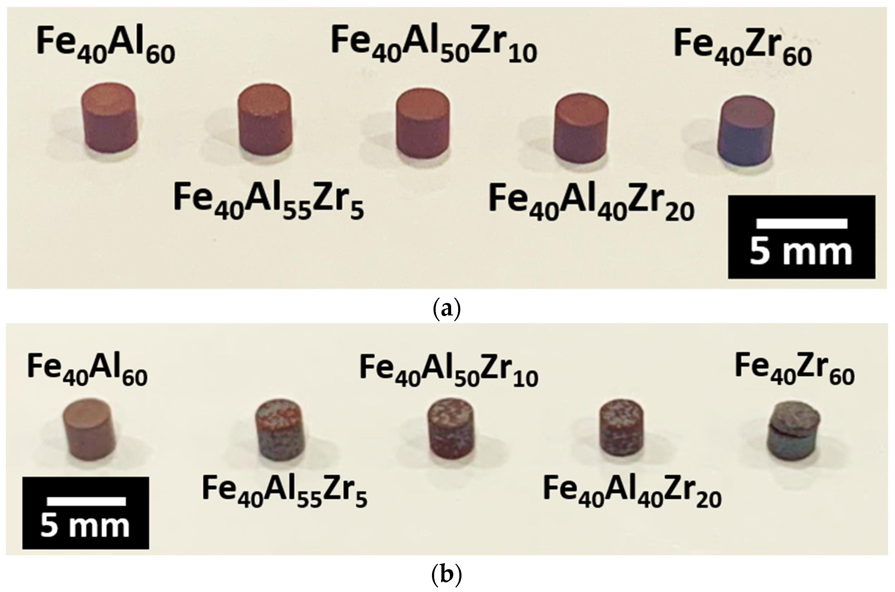
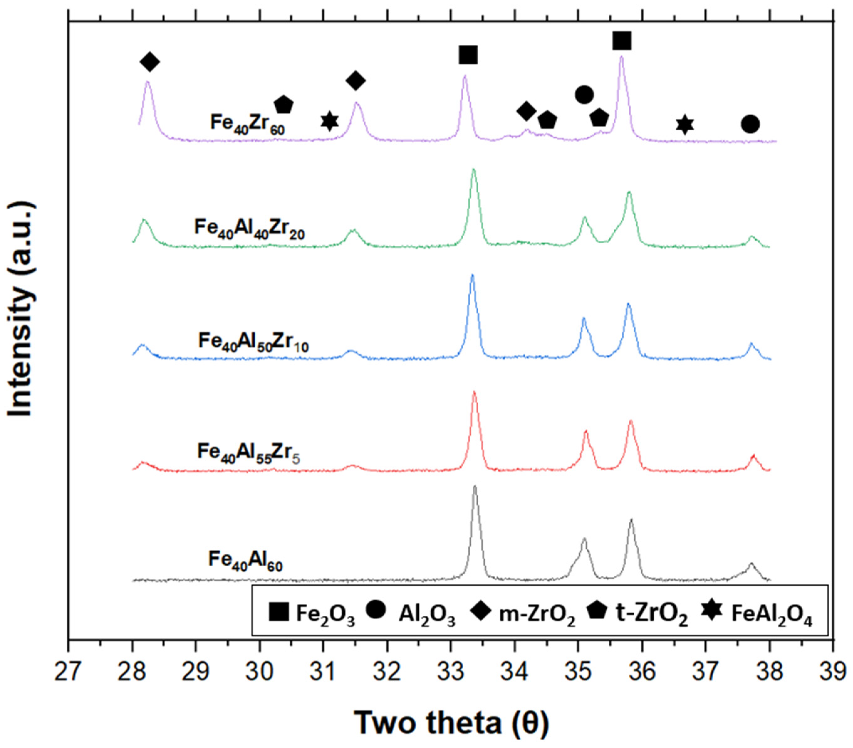
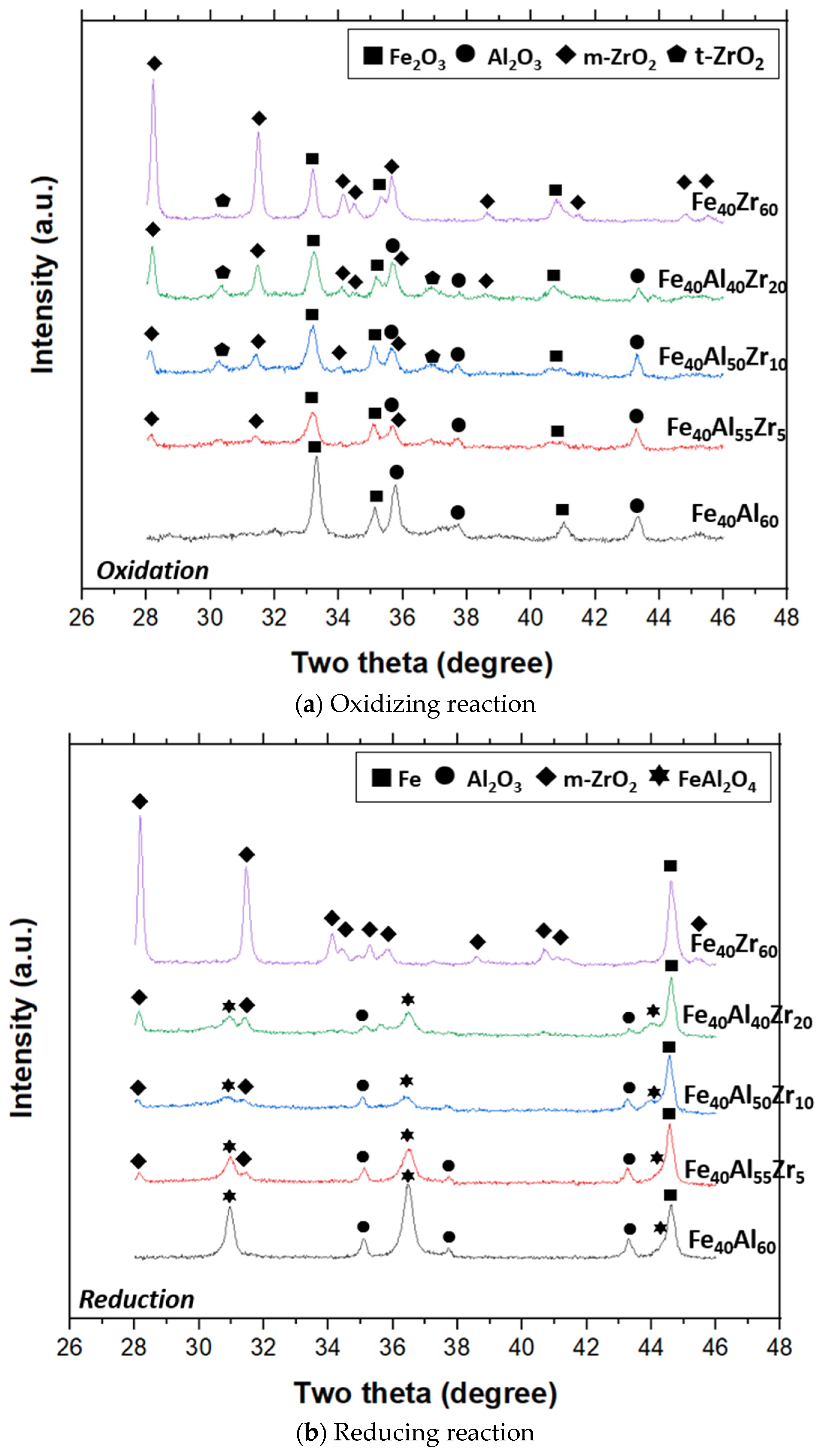
3.1. Characterization of the As-Sintered Composites

The images of the as-sintered samples are displayed in Figure 3a. The samples were deep brick red and turned darker with an increase in the zirconia content. The dimensions of the as-sintered samples are listed in Table 2. All of the samples had a similar diameter and height after sintering at 1200 °C. The images of the as-sintered samples after 50 redox reaction cycles are depicted in Figure 3b.
As demonstrated in Table 2, except for the Fe40Zr60, all of the as-sintered samples presented a similar relative density. Several factors can influence the relative density; the phase transformation process of zirconia might be the major reason in the present case. Zirconia will undergo phase transformation from its tetragonal to monoclinic phase during the cooling process, for which the transformation temperature is around 1100 °C. This phase transformation typically produces approximately 5% to 8% volume expansion [35], thus forming some cracks inside the bulk. Moreover, the higher densification temperature needed for ZrO2 (1500–1600 °C) than that of Al2O3 (1400–1500 °C) was another reason for the lower density of ZrO2-added samples [36,37].
XRD analysis was used for the phase identification in this study. In the phase diagram of iron oxides and zirconia, there is no second formed within the operating temperature in this study. In case of the phase diagram of iron oxides and alumina, FeAl2O4 is one of the most common phases existing in iron oxide and alumina composites [38]. The formation of FeAl2O4 might decrease the reactivity for the chemical looping process because it limits the phase transformation of iron [5]. The main peaks for FeAl2O4 were located at 31.1° and 36.6° in the XRD pattern, which was revealed in previous study [39], and cannot be detected in the as-sintered samples, presented in Figure 4.
For the increase of zirconia content, the peaks which are identified as the monoclinic phase (m-ZrO2) located at 28.2° and 31.4° gradually appear. Furthermore, the intensity of the tetragonal phase (t-ZrO2) peaks, which represent the high temperature phase of zirconia, was too weak to be found in Figure 4. The results of XRD suggest that most of the zirconia have undergone the phase transformation during the cooling process, which led some cracks produced within the samples. This might be the reason that the zirconia addition sample has the lowest relative density, which is listed in Table 2.

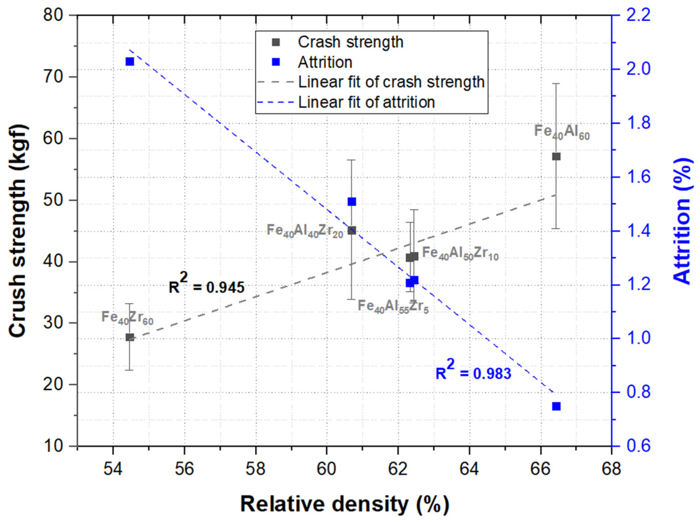
3.2. Mechanical Properties

The crushing strength and attrition, two of the most critical factors, of the as-sintered samples were measured to evaluate their lifetime in chemical looping. For either a fluidized bed or moving bed reactor in chemical looping, the material should be sufficiently strong to withstand the impacts of several looping cycles.
The value of crush strength can be used as the index for estimation of how well a particle withstands impacts during the looping system. In addition, the value of attrition can serve as the index of the resistance of attrition between each particle.
The influence of relative density on the crushing strength and attrition of the as-sintered samples is displayed in Figure 5. The result suggests that both crushing strength and attrition were highly dependent and exhibited a linear relationship with relative density, for which the R-squared values were 0.945 and 0.983, respectively.
The addition of ZrO2 in Fe2O3 had a negative effect on the mechanical properties. Typically, with the increase of zirconia content, crushing strength decreased and attrition increased. This is because most of the mechanical properties, especially strength, are highly dependent on the relative density [40]. The difference of relative density for as-sintered samples was thus the major influence upon both crushing strength and attrition.

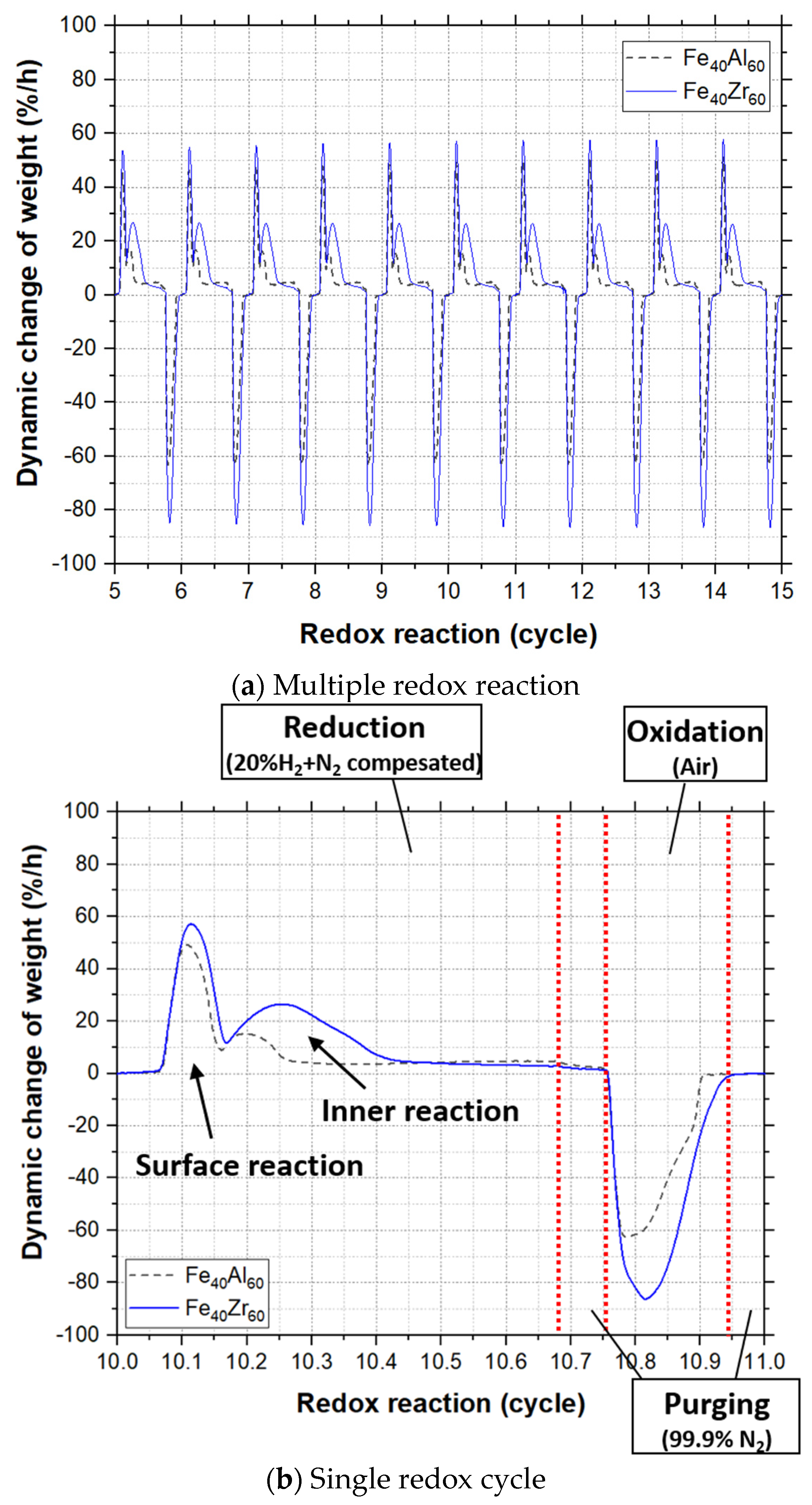
3.3. Capacity of Oxygen for the Composites

Three individual samples for each iron-based composition were measured by TGA analysis in order to ensure reproducibility. The setting parameter of TGA analysis in this study was referred to the Ellingham diagram, which can estimate the equilibrium phase in certain thermodynamic conditions [41]. According to the application for CLHG, Fe2O3 should be reduced to Fe or FeO. The performed atmosphere for TGA analysis was therefore set in air (oxidation) and 20% H2 with N2 compensation (reduction) at 900 °C.
TGA could be regarded as the small scale of a fixed bed reactor. Each sample was set in the alumina crucible and hung inside the furnace. The sample was reduced by reduction gas, and the weight of the sample was then decreased due to the oxygen was released. Afterward, nitrogen was used as the purge gas, which removed the reduction gas remaining from the furnace. Air was subsequently switched to the furnace, so that the sample could capture oxygen from the air to oxidize and then increase its weight. The definition of the capacity of oxygen is given in Section 2.4. The capacity of oxygen for the as-sintered samples with 50 redox cycles is displayed in Figure 6. All of the reacted samples showed a drastic decline for their capacity of oxygen in the first 10 redox cycles and became more stable after the 15th cycle.
The samples at the 15th cycle in the oxidizing and reducing reaction were chosen for TGA analysis. The reason for the decrease of the capacity of oxygen could then be determined. The cooling process was carried out at the relatively fast ramp of 10 °C/min in order to maintain its phase from measurement temperature. Through the analysis of XRD, the phase which existed in reducing and oxidizing reaction can be obtained, presented in Figure 7. The results of XRD measurement are also summarized in Table 3.
The composition of phase is similar between the sample in the oxidizing reaction and the as-sintered one regardless of the addition of alumina or the zirconia composites. However, for the composites with an alumina addition in reducing reaction, a spinel phase FeAl2O4 was formed. FeAl2O4 was mainly composited of FeO and Al2O3. The formation of FeAl2O4 restricted Fe2O3 completely reduced to Fe which decreased the capacity of oxygen. On the other hand, all of the Fe2O3 can fully convert to Fe in the zirconia addition sample due to the lack of second phase formation. The conversion to Fe from Fe2O3 can promote the efficiency of chemical looping hydrogen generation, as presented in Equation (1). The increase of the capacity of oxygen can also provide more oxygen to react with fuel, which can generate more heat during oxidation reaction to achieve the thermal equilibrium for the chemical looping system. In terms of thermodynamics, the addition of zirconia is more suitable than that of alumina in iron-based composite for chemical looping hydrogen generation.

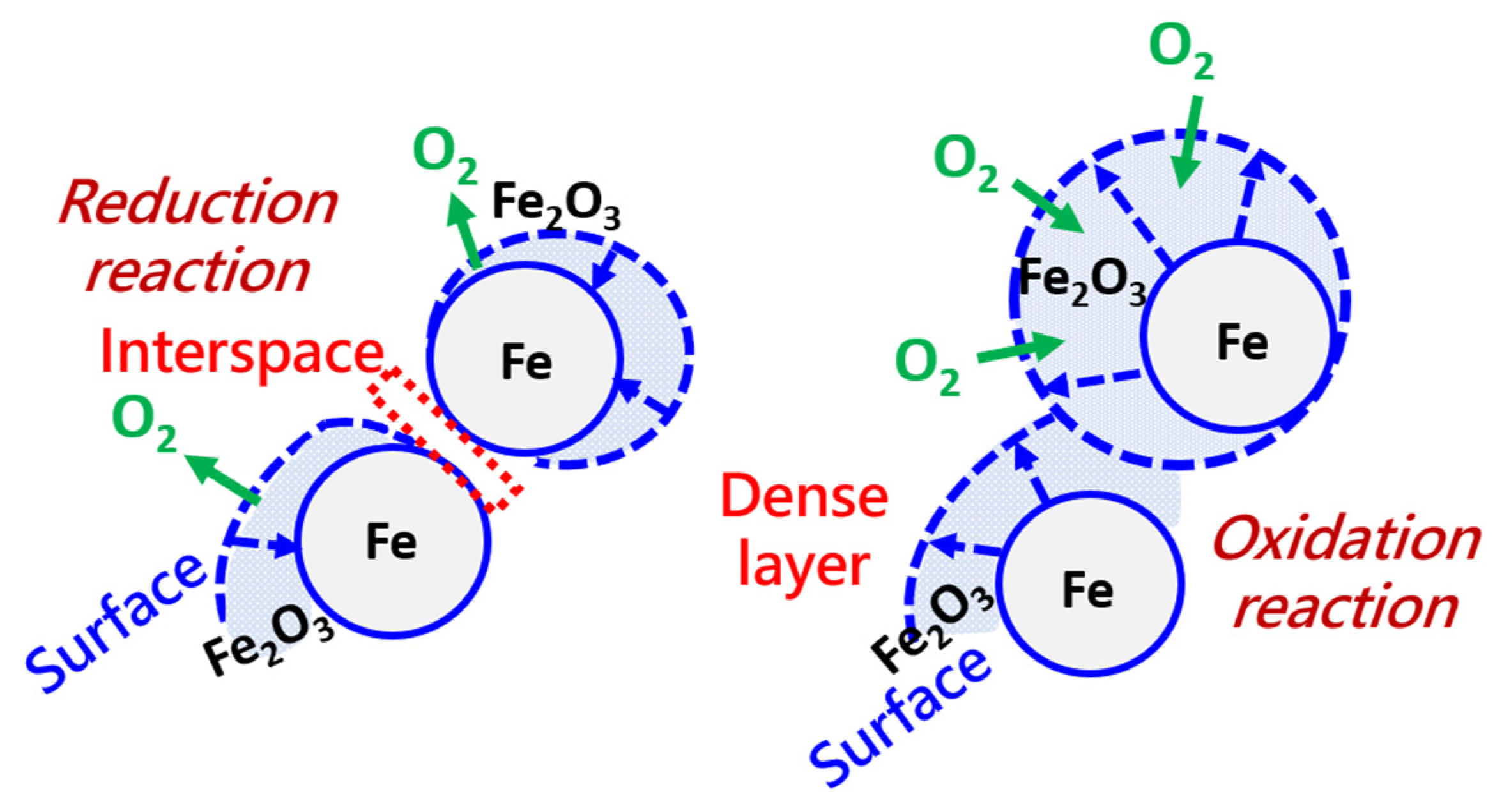
3.4. Influence of the Microstructure on Oxygen Carrier

All of the samples for SEM observation were mounted in epoxy and then ground and polished to obtain the cross-sectional view from the surface to the bulk. The corresponding microstructures of as-sintered and the samples with 50 redox cycles are depicted in Figure 8a,b, respectively. The bright particles can be identified as Fe2O3 (M = 159.69 g/mol) because they have a higher molecular weight than Al2O3 (M = 101.96 g/mol) and ZrO2 (M = 123.218 g/mol), which was verified through EDS measurements (not shown in the present study).
Cracks can be observed in the Fe40Al40Zr20 and Fe40Zr60 samples, presented in Figure 8a, and this echoes the phase transformation of zirconia. The further analysis of this layer was conducted by using EDS mapping, and was identified as the Fe2O3, presented in Figure 8c. Moreover, its thickness increased along with the zirconia addition, given in Figure 8b. This layer could reach almost 5 μm in thickness for the Fe40Zr60 sample.
This Fe2O3 layer acted as the barrier that inhibited the fuel gas reacting with the inner material. The capacity of oxygen thus decreased with the redox reaction in the samples of Fe40Al40Zr20 and Fe40Zr60. In case of the Fe40Al40Zr20, due to the influence from both the formation of FeAl2O4 and the dense layer of Fe2O3 formed on the surface, it exhibited the lowest capacity of oxygen after 50 redox reactions, presented in Figure 7. On the other hand, for the sample of Fe40Zr60, the Fe2O3 layer was peeled off from the bulk because its thickness was too thick. The fresh surface appeared again and could react to the inner material again, which could maintain its reactivity.
More detailed analysis of the dense Fe2O3 layer formed on the surface was needed. In this study, the proposed mechanism of the formation for Fe2O3 layer and its corresponding kinetic analysis is given in Figure 9 and Figure 10.

3.5. Kinetic Analysis for Redox Reaction

The kinetic analysis given in Figure 9 for redox reaction was through the thermalgravity measurement. Each redox reaction exhibited a similar result within the 50 cycles, presented in Figure 9a. Two distinct peaks can be found during the reduction reaction, and only one peak during oxidation. The further analysis of single redox at 10th cycle reaction is displayed in Figure 9b. Two distinct peaks can be found during the reduction reaction and only one peak during oxidation.
During the oxidation reaction, iron on the surface was oxidized by oxygen to Fe2O3. Meanwhile, the volume of Fe2O3 particles expanded, which is presented in Figure 10. Afterward, each Fe2O3 particles were closer together, which led them to easily sinter together; the dense layer was then formed on the surface. This dense layer acted as a barrier which inhibited the reaction between the inner material and fuel gas. The corresponding kinetics curve for the oxidizing reaction was exhibited in Figure 9b. Only one characteristic peak formed in the oxidizing reaction with the fastest reaction rate which was the special feature for the surface reaction. In addition, no other peak could be observed in the oxidation reaction, which indicated that the dense Fe2O3 layer covered the entire sample and then inhibited the inner material reaction.
The proposed schematic diagram for the reducing reaction is given in Figure 10. Fe2O3 reacted with the reducing gas, and then was reduced to Fe. Because the volume of particles shrank, the interspace between each particle was formed. Afterward, reducing gas could further react with the inner material. Two characteristic peaks can be obtained in the kinetic analysis diagram during reducing reaction, presented in Figure 9b. The first peak exhibited the faster reaction rate and was the initial reaction; it was the reaction between surface particles and the reducing gas.
The second peak with the feature of a slower reaction rate and longer reaction time period could be regarded as the inner reaction. According to Figure 10, the reduction reaction that happened in the inner material should rely on the interspace which was formed through particle shrinkage. The reaction was thus needed to take more time to occur layer by layer. In case of the Fe40Al60, the shrinkage of particle volume from Fe2O3 to FeAl2O4 was not as much compared to Fe2O3 to Fe. The width of the interspace could be assumed to be smaller than that of Fe40Zr60, in which all of the Fe2O3 could be completely reduced to Fe. The rate for inner reaction during reduction was therefore slower than that of Fe40Zr60.

3.6. Formation of the Fe2O3 Layer

The phase separation effect can result in the driving force of the formation of the Fe2O3 layer. A previous study using an Fe-Ni-O composite revealed phase separation similar to that in the present study; the Kirkendall effect was introduced to explain this phenomenon [42]. Outward and inward diffusion was produced because of the different diffusion coefficients of the Fe and Ni atoms. The core–shell structure (Ni core and Fe shell) was then formed.
For the microstructural images presented Figure 8, the phase separation effect derived from outward and inward diffusion indeed affected the composite in this study. Moreover, the effect of phase separation was enhanced significantly in zirconia addition samples than that of the alumina addition. This is caused by different phases of iron.
In the case of the FeZr composite, all of Fe2O3 was completely reduced to Fe during the reducing reaction, listed in Table 3. Because Fe has a lower Tamman point (764 °C) than the operating temperature (900 °C) conducted in the reducing reaction, Fe will then segregate to the surface by several redox reactions. On the other hand, for the FeAl composite, only part of Fe2O3 can only be reduced to FeO, and then reacts with alumina to become the spinel structure of FeAl2O4. The higher Tamman point of FeAl2O4 (890 °C) than that of Fe (764 °C) could restrict the Fe segregated to the surface. The phase separation effect was therefore less influenced in the FeAl composite than that in the FeZr.

4. Conclusions

This feasibility study evaluated iron-based composites added with Al2O3 and ZrO2 as oxygen carriers for chemical looping applications. Their corresponding microstructures before and after 50 redox reaction cycles were also analyzed. As for the mechanical properties, both crushing strength and attrition were influenced by the relative density of the bulk. For the measurement of the capacity of oxygen, all of the as-sintered samples presented a drastic decrease within the first 10 redox cycles. An Fe2O3 layer that formed on the surface acted as a barrier to inhibit further redox reactions with the inner layer material.
In this study, the phase in oxidizing and reducing reaction was revealed and analyzed. Both the phases of FeAl2O4 and Fe were formed in the alumina addition samples, but only Fe was produced in the zirconia addition sample during the reduction reaction. The formation of FeAl2O4 inhibited Fe2O3 complete reduction to Fe, which might decrease the efficiency if it is used for chemical looping hydrogen generation.
A dense layer which was identified as Fe2O3 in the bulk surface was found in the samples with 50 redox cycles. It acted as the barrier which inhibited the reaction between the inner materials and fuel gas. The capacity of oxygen for zirconia addition composites was then influenced.
Through the kinetic analysis during oxidizing and reducing reaction, the formation of an Fe2O3 layer was revealed in this study. Zirconia as the additive for iron-based composite was more suitable for chemical looping hydrogen generation than that of alumina. However, the cracks which derived from zirconia’s phase transformation should be avoided if it is applied in either a fluidized bed or moving bed reactor.

Author Contributions

Conceptualization, C.-T.K. and H.-W.H.; methodology, C.-T.K. and C.-H.S.; validation, C.-H.S. and H.-W.H.; resources, C.-H.S. and H.-W.H.; data curation, C.-T.K.; writing—original draft preparation, C.-T.K.; writing—review and editing, C.-H.S.; project administration, C.-H.S.; funding acquisition, H.-W.H. All authors have read and agreed to the published version of the manuscript.

Funding

This research was funded by Bureau of Energy, Ministry of Economic Affairs, Taiwan, project number 109-E0216.

Informed Consent Statement

Not applicable.

Data Availability Statement

The data presented in this study are available on request from the corresponding author.

Conflicts of Interest

There is no conflict of interest.

References

  1. Figueroa, J.D.; Fout, T.; Plasynski, S.; McIlvried, H.; Rameshwar, D. Srivastava Advances in CO2 capture technology-The U.S. Department of Energy’s Carbon Sequestration Program. Int. J. Greenh. Gas Control 2008, 2, 9–20. [Google Scholar] [CrossRef]
  2. Taiwan Power Company. Taiwan Power Company Sustainability Report. 2019. Available online: https://www.taipower.com.tw (accessed on 1 December 2020).
  3. International Energy Agency. Key World Energy Statistics. 2020. Available online: https://www.iea.org/ (accessed on 1 May 2021).
  4. Fang, H.; Haibin, L.; Zengli, Z. Advancements in development of chemical-looping combustion: A review. Int. J. Chem. Eng. 2009, 2009, 710515. [Google Scholar] [CrossRef]
  5. Fan, L.S. Chemical Looping Systems for Fossil Energy Conversions; John Wiley & Sons, Inc.: Hoboken, NJ, USA, 2010. [Google Scholar]
  6. Jerndal, E.; Mattisson, T.; Lyngfelt, A. Investigation of different NiO/NiAl2O4 particles as oxygen carriers for chemical-looping combustion. Energy Fuels 2009, 23, 665–676. [Google Scholar] [CrossRef]
  7. Imtiaz, Q.; Hosseini, D.; Muller, C.R. Review of Oxygen Carriers for Chemical Looping with Oxygen Uncoupling (CLOU): Thermodynamics, Material Development, and Synthesis. Energy Technol. 2013, 1, 633–647. [Google Scholar] [CrossRef]
  8. Shah, K.; Moghtaderi, B.; Wall, T. Selection of Suitable Oxygen Carriers for Chemical Looping Air Separation: A Thermodynamic Approach. Energy Fuels 2012, 4, 2038–2045. [Google Scholar] [CrossRef]
  9. Farooq, S.; Ruthven, D.M.; Boniface, H.A. Numerical simulation of a pressure swing adsorption oxygen unit. Chem. Eng. Sci. 1989, 44, 2805–2816. [Google Scholar] [CrossRef]
  10. Fan, J.; Zhu, L. A novel technique based on coal gasification integrated with chemical looping air separation. J. Fundam. Renew. Energy Appl. 2015, 5, 150. [Google Scholar]
  11. Zhou, C.; Shah, K.; Moghtader, B. Techno-Economic Assessment of Integrated Chemical Looping Air Separation for Oxy-Fuel Combustion: An Australian Case Study. Energy Fuels 2015, 29, 2074–2088. [Google Scholar] [CrossRef]
  12. Tong, A.; Bayham, S.; Kathe, M.V.; Zeng, L.; Luo, S.; Fan, L.S. Iron-based syngas chemical looping process and coal-direct chemical looping process development at Ohio State University. Appl. Energy 2014, 113, 1836–1845. [Google Scholar] [CrossRef]
  13. Sorgenfrei, M.; Tsatsaronis, G. Design and evaluation of an IGCC power plant using iron-based syngas chemical-looping (SCL) combustion. Appl. Energy 2014, 113, 1958–1964. [Google Scholar] [CrossRef]
  14. Luo, M.; Yi, Y.; Wang, S.; Wang, Z.; Du, M.; Pan, J.; Wang, Q. Review of hydrogen production using chemical-looping. Renew. Sust. Energy Rev. 2018, 81, 3186–3214. [Google Scholar] [CrossRef]
  15. Kathe, M.V.; Empfield, A.; Na, J.; Blair, E.; Fan, L.S. Hydrogen production from natural gas using an iron-based chemical looping technology: Thermodynamic simulations and process system analysis. Appl. Energy 2016, 165, 183–201. [Google Scholar] [CrossRef]
  16. Kang, K.S.; Kim, C.H.; Bae, K.K.; Cho, W.C.; Kim, S.H.; Park, C.S. Oxygen-carrier selection and thermal analysis of the chemical-looping process for hydrogen production. Int. J. Hydrogen Energy 2010, 35, 12246–12254. [Google Scholar] [CrossRef]
  17. Aghaie, M.; Mehrpooya, M.; Pourfayaz, F. Introducing an integrated chemical looping hydrogen production, inherent carbon capture and solid oxide fuel cell biomass fueled power plant process configuration. Energy Convers. Manag. 2016, 124, 141–154. [Google Scholar] [CrossRef]
  18. Chen, S.; Xue, Z.; Wang, D.; Xiang, W. An integrated system combining chemical looping hydrogen generation process and solid oxide fuel cell/gas turbine cycle for power production with CO2 capture. J. Power Sources 2012, 215, 89–98. [Google Scholar] [CrossRef]
  19. Nurdiawati, A.; Zaini, I.N.; Irhamna, A.R.; Sasongko, D.; Aziz, M. Novel configuration of supercritical water gasification and chemical looping for highly-efficient hydrogen production from microalgae. Renew. Sust. Energy Rev. 2019, 112, 369–381. [Google Scholar] [CrossRef]
  20. Chisalita, D.A.; Cormos, C.C. Techno-economic assessment of hydrogen production processes based on various natural gas chemical looping systems with carbon capture. Energy 2019, 181, 331–344. [Google Scholar] [CrossRef]
  21. Gupta, G.; Velazquez-Vargas, L.G.; Fan, L.-S. Syngas Redox (SGR) Process to Produce Hydrogen from Coal Derived Syngas. Energy Fuels 2007, 21, 2900–2908. [Google Scholar] [CrossRef]
  22. Hossain, M.M.; de Lasa, H.I. Chemical-looping combustion (CLC) for inherent separations-a review. Chem. Eng. Sci. 2008, 63, 4433–4451. [Google Scholar] [CrossRef]
  23. Ada´nez, J.; de Diego, L.F.; García-Labiano, F.; Gayán, P.; Abad, A.; Palacios, J.M. Selection of oxygen carriers for chemical-looping combustion. Energy Fuels 2004, 18, 371–377. [Google Scholar] [CrossRef]
  24. Piran, R.K.; Cleeton, J.P.E.; Stuart, A.S.; John, S.D.; Christopher, D.B. Interaction of Iron Oxide with Alumina in a Composite Oxygen Carrier during the Production of Hydrogen by Chemical Looping. Energy Fuels 2012, 26, 603–617. [Google Scholar]
  25. Zhao, H.B.; Mei, D.F.; Ma, J.C.; Zheng, C.G. Comparison of preparation methods for iron–alumina oxygen carrier and its reduction kinetics with hydrogen in chemical looping combustion. Asia-Pac. J. Chem. Eng. 2014, 9, 610–622. [Google Scholar] [CrossRef]
  26. Ma, S.W.; Chen, S.Y.M.; Ahsanullah, S.W.G. Effects of CeO2, ZrO2, and Al2O3 Supports on Iron Oxygen Carrier for Chemical Looping Hydrogen Generation. Energy Fuels 2017, 31, 8001–8013. [Google Scholar] [CrossRef]
  27. Zeng, D.; Kang, F.; Qiu, Y.; Cui, D.; Li, M.; Ma, L.; Zhang, S.; Xiao, R. Iron oxides with gadolinium-doped cerium oxides as active supports for chemical looping hydrogen production. Chem. Eng. J. 2020, 396, 125153. [Google Scholar] [CrossRef]
  28. Yüzbasi, N.S.; Kierzkowska, A.; Müller, C. Development of Fe2O3-based, Al2O3-stabilized oxygen carriers using sol-gel technique for H2 production via chemical looping. Enrgy. Proced. 2017, 114, 436–445. [Google Scholar] [CrossRef]
  29. Bechta, S.V.; Krushinov, E.V.; Almjashev, V.I.; Vitol, S.A.; Mezentseva, L.P.; Petrovc, Y.B.; Lopukh, D.B.; Khabensky, V.B.; Barrachin, M.; Hellmann, S.; et al. Phase diagram of the ZrO2–FeO system. J. Nucl. Mater. 2006, 348, 114–121. [Google Scholar] [CrossRef]
  30. Jones, T.S.; Kimura, S.; Muan, A. Phase Relations in the System FeO-Fe2O3-ZrO2-SiO2. J. Am. Ceram. Soc. 1967, 50, 137–142. [Google Scholar] [CrossRef]
  31. Feng, Y.; Wang, N.; Guo, X.; Zhang, S. Dopant screening of modified Fe2O3 oxygen carriers in chemical looping hydrogen production. Fuel 2020, 262, 116489. [Google Scholar] [CrossRef]
  32. Technical Data-Coefficient of Thermal Expansion, Kyocera Global. 2020. Available online: https://global.kyocera.com/prdct/fc/list/tokusei/bouchou/index.html (accessed on 1 December 2020).
  33. Takeda, M.; Onishi, T.; Nakakubo, S.; Fujimoto, S. Physical properties of iron-oxide scales on Si-containing steels at high temperature. Mater. Trans. 2009, 50, 2242. [Google Scholar] [CrossRef] [Green Version]
  34. Chiu, P.C.; Ku, Y.; Wu, Y.L.; Wu, H.C.; Kuo, Y.L. Characterization and evaluation of prepared Fe2O3/Al2O3 oxygen carriers for chemical looping process. Aerosol Air Qual. Res. 2014, 14, 981–990. [Google Scholar] [CrossRef] [Green Version]
  35. Chevalier, J.; Gremillard, L.; Virkar, A.V.; David, R. Clarke the Tetragonal-Monoclinic Transformation in Zirconia: Lessons Learned and Future Trends. J. Amer. Ceram. Soc. 2009, 92, 1901–1920. [Google Scholar] [CrossRef]
  36. Xie, Z.P.; Yang, J.L.; Huang, Y. Densification and grain growth of alumina by microwave processing. Mater. Lett. 1998, 37, 215–220. [Google Scholar] [CrossRef]
  37. Li, D.; Liu, Y.S.; Zhong, Y.; Liu, L.F.; Erik, A.; Shen, Z.J. Dense and strong ZrO2 ceramics fully densified in <15 min. Adv. Appl. Ceram. 2019, 118, 23–29. [Google Scholar] [CrossRef] [Green Version]
  38. Dreval, L.; Zienert, T.; Fabrichnaya, O.J. Calculated phase diagrams and thermodynamic properties of the Al2O3–Fe2O3–FeO system. J. Alloys Compd. 2016, 657, 192–214. [Google Scholar] [CrossRef]
  39. Enhessari, M. FeAl2O4 Nanopowders; Structural Analysis and Band Gap Energy. High Temp. Mat. Proc. 2017, 36, 789–793. [Google Scholar] [CrossRef]
  40. Wei, K.; Peng, Y.; Qu, Z.L.; He, R.; Cheng, X.M. High temperature mechanical behaviors of lightweight ceramic corrugated core sandwich panel. Compos. Struct. 2017, 176, 379–387. [Google Scholar] [CrossRef]
  41. Gaskell, D.R. Introduction to the Thermodynamics of Materials; Taylor & Francis: Boca Raton, FL, USA, 2012. [Google Scholar]
  42. Qin, L.; Majumder, A.; Fan, J.A.; Kopechek, D.; Fan, L.S. Evolution of nanoscale morphology in single and binary metal oxide microparticles during reduction and oxidation processes. J. Mater. Chem. A 2014, 2, 17511–17520. [Google Scholar] [CrossRef]
Figure 1. Schematic of the chemical looping process.
Crystals 11 00971 g001
Figure 2. Schematic of the chemical looping combustion, chemical looping oxygen uncoupling, and chemical looping air separation.
Crystals 11 00971 g002
Figure 3. Images of (a) the as-sintered samples and (b) after 50 redox reaction cycles at 900 °C.
Crystals 11 00971 g003
Figure 4. Narrow scan of XRD pattern for as-sintered samples.
Crystals 11 00971 g004
Figure 5. Relationship among the relative density, crushing strength, and attrition of the as-sintered samples.
Crystals 11 00971 g005
Figure 6. Capacity of oxygen for the as-sintered samples with 50 redox reaction cycles.
Crystals 11 00971 g006
Figure 7. XRD pattern for the as-sintered samples reacted at 15th cycle in (a) oxidizing and (b) reducing reaction.
Crystals 11 00971 g007
Figure 8. Cross-sectional view for (a) as-sintered samples and (b) after 50 redox reaction cycles at 900 °C, and (c) EDS mapping result for Fe2O3 layer formed in surface of the specimen.
Crystals 11 00971 g008aCrystals 11 00971 g008b
Figure 9. (a) Reaction kinetic analysis for redox reaction and (b) further analysis for single redox reaction.
Crystals 11 00971 g009
Figure 10. Schematic for the reaction between oxidizing and reducing reaction.
Crystals 11 00971 g010
Table 1. Denotations and compositions of the composites in the present study.
CompositionFe2O3 Content
(wt%)
Al2O3 Content
(wt%)
ZrO2 Content
(wt%)
Fe40Al6040600
Fe40Al55Zr540555
Fe40Al50Zr10405010
Fe40Al40Zr20404020
Fe40Zr6040060
Table 2. Summary of relative densities and dimensions of the as-sintered samples.
ZrO2 Content
(wt%)
Relative Density (%)Porosity
(%)
Dimension
Height (mm)Diameter (mm)
066.42 ± 1.9633.582.55 ± 0.022.85 ± 0.03
562.32 ± 0.9937.682.65 ± 0.042.85 ± 0.02
1062.43 ± 5.4937.572.68 ± 0.032.87 ± 0.03
2060.68 ± 1.4539.322.58 ± 0.022.85 ± 0.01
6054.45 ± 5.8145.552.38 ± 0.042.77 ± 0.02
Table 3. Summary of the phase composition for the iron-based composites with alumina and zirconia addition.
CompositesPhase Composition
As-SinteredOxidationReduction
Fe40Al60Fe2O3, Al2O3Fe2O3, Al2O3FeAl2O4, Al2O3, Fe
Fe40Al55Zr5Fe2O3, Al2O3, m-ZrO2Fe2O3, Al2O3, m-ZrO2FeAl2O4, Al2O3, Fe, m-ZrO2
Fe40Al50Zr10Fe2O3, Al2O3, m-ZrO2Fe2O3, Al2O3, m-ZrO2, t-ZrO2FeAl2O4, Al2O3, Fe, m-ZrO2
Fe40Al40Zr20Fe2O3, Al2O3, m-ZrO2Fe2O3, Al2O3, m-ZrO2 t-ZrO2FeAl2O4, Al2O3, Fe, m-ZrO2
Fe40Zr60Fe2O3, m-ZrO2, t-ZrO2Fe2O3, Al2O3, m-ZrO2Fe, m-ZrO2
Publisher’s Note: MDPI stays neutral with regard to jurisdictional claims in published maps and institutional affiliations.

