Article

Optimization of the Physical and Mechanical Properties of Grouting Material for Non-Soil-Squeezing PHC Pipe Pile

1
School of Civil and Transportation Engineering, Guangdong University of Technology, Guangzhou 510006, China
2
State Key Laboratory of Geomechanics and Geotechnical Engineering, Institute of Rock and Soil Mechanics, Chinese Academy of Sciences, Wuhan 430071, China
3
Guangzhou Institute of Building Science Company Limited, Guangzhou 510440, China
*
Author to whom correspondence should be addressed.
Equal contribution.
Crystals 2022, 12(1), 10; https://doi.org/10.3390/cryst12010010
Submission received: 20 October 2021 / Revised: 3 December 2021 / Accepted: 13 December 2021 / Published: 21 December 2021

Abstract

:
The physical and mechanical properties of grouting materials greatly affect the friction resistance and the bearing performance of a non-soil-squeezing PHC pipe pile. Orthogonal tests for four factors at five levels were carried out to optimize the proportion of the water–cement mixture by using Portland cement as a raw material and a water-reducing agent, expansion agent and early-strength agent as additives. The following conclusions were obtained: (1) Both the water–cement ratio and the dosage of water-reducing agent are positively correlated with the fluidity of the water–cement mixture and have the greatest influence on the fluidity, followed by the expansion agent and early-strength agent. The saturation point of the water-reducing agent is 1.5%. (2) The strength of the grouting body decreases linearly with the increase of the water–cement ratio, and the dosage of the water-reducing agent has no obvious effect on the strength. As the dosage of expansion agent increases, the strength of the grouting body decreases rapidly. The expansion agent mainly plays a key role in the middle and late stages of the hardening process of the slurry. Early-strength agents have a greater impact on the early strength, but less on the later strength. When the slurry is solidified for 3 h, the early-strength agent has the greatest impact on the strength with an optimal dosage of 5%. (3) The volume of the grouting body has an inverse relationship with the water–cement ratio, and the optimal amount of expansion agent is 12%. The incorporation of an expansion agent makes the volume increase of the grouting body exceed the volume shrinkage ratio caused by the hardening of the grouting body with a curing time of more than 3 days, ensuring a slight increase in the volume of the grouting body. After 3 days, even though the effect of the expansion agent is gradually weakened, it can still ensure that the volume of the grouting body does not shrink. With the increase of the amount of water-reducing agent, the volume of the grouting body gradually decreases. When the amount of water-reducing agent exceeds 1.5%, the volume of the grouting body no longer decreases. (4) The early-strength agent has almost no effect on the volume of the grouting body. When the curing time is 3 h, the water–cement ratio has the greatest influence on the volume of the grouting body, followed by the water-reducing agent, and, finally, the expansion agent. After 3 h, the water–cement ratio still has the greatest influence, and the influence of the expansion agent gradually exceeds that of the water-reducing agent. The water-reducing agent mainly affects the volume of the grouting body in the water separation stage, and the expansion agent mainly plays a role in the middle and late stages of the slurry solidification. After optimized ratio analysis, the fluidity of the water–cement mixture can be improved, the volume shrinkage ratio rate can be lowered and the early strength can be increased.

1. Introduction

Drilling with PHC pipe cased pile (hereinafter referred to as DPC pile) [1,2,3] is a new type of non-soil-squeezing PHC pipe pile that has characteristics of no mud discharge and a large diameter (800–1400 mm) and is energy efficient and environmentally friendly. DPC pile has significantly overcome the damage to the pipe pile body and has greatly reduced the noise and vibration pollution caused and generated by traditional pile-sinking construction technology, such as the hammer impulse method or static pressure method. Compared with traditional cast-in-situ bored pile, there is no mud discharge during the construction of this new pile foundation, preventing the groundwater, rivers and municipal pipe networks from being polluted. As shown in Figure 1, due to its special construction process of hole drilling, pile sinking and soil dumping simultaneously, a clearance (hereinafter referred to as pile-soil clearance) with a width of about 10 mm and a length of more than 20 m between the PHC pipe pile wall and the hole wall is formed. In order to regain and increase the skin friction of DPC pile, it is necessary to carry out lateral pile grouting through a grouting pipe embedded in the pipe wall of the DPC pile. After the grouting liquid flows out from the grouting outlet at the bottom of the pile, it will flow from bottom to top along the lathy pile-soil clearance to bind the pipe pile and the soil around the pile as a whole. At the same time, the slurry spreads to the soil in the form of claws and capillary claws, thereby improving the skin friction and ultimate bearing capacity of the DPC pile. The flow and diffusion effect of the grouting liquid in the long and narrow pile-soil clearance ultimately determines the magnitude of the lateral pile skin friction. A number of studies have shown that a poor lateral pile grouting effect can lead to a decrease in its bearing performance by more than 26.60% [4] Thus, the lateral pile grouting carried out in the lathy pile-soil clearance puts forward higher requirements on the physical and mechanical properties of grouting materials, especially fluidity, stability and compressive strength.
The ideal grouting material for DPC pile should generally have the characteristics of being irrigable, adjustable and controllable, the details of which are as follows.
(1) Good liquidity ability: The liquidity of grouting slurry should not only satisfy the grouting requirements of the pre-stressed structures, such as pipes with different diameters and grout outlets, but also should be able to maintain the grouting slurry with a good flow effect in the lathy pile-soil clearance. (2) Micro-expansibility: The grouting stone should have a certain expansion performance or at least be able to maintain a non-shrinking state to reduce the releasing of the lateral soil pressure along the pile caused by the volume shrinkage ratio of the grouting stone, thereby increasing its skin friction. (3) High compressive strength: The grouting stone should not only have the characteristics of higher early compressive strength to effectively shorten the construction period, but also have long-term compressive strength to steadily resist the pile foundation settlement caused by the vertical load on the pile cap. (4) Good diffusion ability: In order to increase the volume of the slurry spreading to the soil around the piles to enhance the occlusion between the slurry and the soil, the particle size of the solid particles in grouting slurry should be small enough to penetrate into the small cracks, pores and gaps between soil particles. (5) Good underwater anti-dispersible property: The grouting slurry should have the ability to maintain the original physical and mechanical properties in the groundwater. (6) Good compatibility: The grouting slurry should provide a good compatibility with the admixture to be able to accurately control the pumping period of the mixture. (7) Rich source of raw materials: The raw materials used in the grouting slurry should have the advantages of abundant sources, simple acquisition, low price, simple configuration process and low engineering cost. (8) Other advantages: In addition to the above advantages, the grouting slurry should also have the advantages of well stability, high durability, strong corrosion resistance, anti-aging performance, anti-penetrability performance, and be able to save energy, protect the environment and be non-toxic and harmless. Generally speaking, it is difficult for grouting materials to meet all the above conditions at the same time, thus the performance index of grouting materials can be selected to meet a certain number of the above characteristics according to the grouting requirements and actual engineering conditions.
Different projects have different requirements for grouting materials, whose one or several properties can generally be changed by adding corresponding additives to the main agent. Scholars have evaluated grouting materials mainly in terms of liquidity ability, expansibility, compressive strength, diffusion ability, their underwater anti-dispersible property, compatibility, setting time and other aspects [5,6,7,8,9,10,11]. On the whole, grouting materials have experienced long-term development, and a wealth of results have been formed. At present, commonly used grouting materials in engineering include cement slurries and chemical slurries [12,13,14,15]. Although chemical slurries have obvious advantages, such as low viscosity, controllable gel time and super injection capacity, ensuring the slurry can enter small cracks or pores, they also have many shortcomings, such as corrosion, dehydration and easy shrinkage. In addition, chemical slurries are generally expensive and have low compressive strength [16,17,18]. Portland cement grout is characterized by good applicability, low cost and economic saving and is currently the most widely used grouting material because its physical and mechanical properties can be significantly improved by adding additives [5,6,8,10,19,20].
The grouting material for the lateral pile grouting of DPC pile should have high fluidity to keep flowing better along the lathy pile-soil clearance. In order to increase the skin friction of DPC pile, the grouting stone should not only have the characteristics of higher early compressive strength to shorten the construction period effectively, but also have a certain expansion performance or at least be able to maintain a non-shrinking state to reduce the releasing of the lateral soil pressure along the pile. Although the existing grouting materials are fruitful, most of them have been developed for different purposes to meet the requirements of different projects. No scholars have carried out targeted research on the grouting material for the lateral pile grouting of DPC pile, and the applicability of the above grouting material system is also a mystery.
In view of this, orthogonal tests of four factors at five different levels were carried out by using Portland cement as a raw material and choosing a water-reducing agent (mainly used to improve the fluidity of the grouting material), expansion agent (mainly used to reduce the volume shrinkage ratio of the grouting stone) and early-strength agent (mainly used to increase the early strength of the grouting material) as additives. The physical and mechanical properties of the grouting material, such as fluidity, volume shrinkage ratio and compressive strength, were systematically analyzed. At last, after optimizing the proportion of the four factors based on these orthogonal tests, the special grouting material suitable for DPC pile was developed.

2. Experimental Program and Test Method

2.1. Grouting Material and Experimental Program

As shown in Table 1, orthogonal tests of four factors at five different levels were carried out to study the physical-mechanical properties of the grouting material by using Portland cement as a raw material and choosing a water-reducing agent, expansion agent and early-strength agent as additives. The cement used in the test was ordinary Portland cement, the performance of which meets the relevant requirements of the General Portland Cement standard (GB175-2007) [21].
The expansion agent used in the test was a concrete low-alkali UEA-type expansion agent. Its alkali content is R20, its fineness is less than 10% and its specific gravity is 2.90. It has the characteristics of low-alkali content, good expansion performance and stability. The expansion agent was a compound mixture, which was made up primarily of C a O , S O 3 and A l 2 O 3 . The swelling agent molecules and the main water–cement mixture molecules undergo a hydration reaction after being mixed together to produce a large number of swelling crystalline hydrates (such as ettringite), i.e., 6 C a O + 3 S O 3 + 3 A l 2 O 3 + 92 H 2 O 3 C a O · A l 2 O 3 · 3 C a S O 4 · 32 H 2 O . The crystal growth of ettringite produces a crystal pressure, which, ultimately, leads to an increase in the volume of the grouting body. The early-strength agent used in the test was solid powder and can be used in various concretes, such as cast-in-place concrete and precast concrete components, the effect of which is obvious. The early-strength agent belongs to the chloride salt series, whose chloride (such as C a C l 2 ) reacts with calcium hydroxide formed by cement hydration to generate non-water-soluble calcium chlorate. The massive generation of calcium chlorate reduces the concentration of calcium hydroxide in the liquid phase and accelerates the hydration rate of tricalcium aluminate ( 3 C a O · A l 2 O 3 ) in the water–cement mixture, after which the skeleton system inside the grouting body will be quickly formed. Therefore, the addition of the early-strength agent accelerates the hydration of the slurry and improves the early strength of the grouting body. The water-reducing agent used in the test was an independently researched and developed mother liquor with a solid content of 10% and a mixing amount of 1.0%. The water-reducing agent significantly reduces the water consumption while maintaining the slump of the concrete basically unchanged, and it is able to obviously improve the fluidity of the slurry under the same water consumption.
Special instructions are as follows: In this paper, the water–cement ratio is defined as the ratio of the mass of all moisture to the mass of all aggregates, and the dosage of water-reducing agent is defined as the percentage of the mass of the mother liquor with a concentration of 4% to the mass of the cement. According to relevant design codes, previous research results and past engineering experience [1,3,22,23], water–cement ratio is determined to be ranging from 0.35 to 0.6, the dosage of water-reducing agent is set to be ranging from 0% to 2%, the percentage of expansion agent content in cement mass is set to be ranging from 0% to 18% and the percentage of the early-strength agent in cement mass is set to be ranging from 0% to 7%. As shown in Table 1, according to the principle of orthogonal experiment design [24], orthogonal table L25 (56) was selected to study the fluidity, the volume growth rate of the grouting body and the compressive strength of the grouting material, and a total of 25 groups of experiments were carried out to optimize the proportion of the four factors.
The method of making water–cement mixture was as follows: The quality of cement and water was determined according to the needs for the orthogonal test under a certain working condition. Then, the dosages of water-reducing agent, expansion agent and early-strength agent was calculated according to the proportion of each additive to the cement mass, respectively. First, the water-reducing agent was added to the water and stirred evenly, followed by the early-strength agent and, finally, the expansion agent. Second, after the mixed liquid containing additives had been thoroughly stirred, the cement was added. This configured water–cement mixture was used to test the fresh properties of the cement liquid, such as its fluidity and bleeding rate. At the same time, during the process of gradual solidification of the slurry, its volume growth rate and compressive strength were also examined. All operations, including all mixing processes and sample preparation, were maintained in accordance with “Test Methods of Basic Performance on Building Mortar” (JGJ70-90) [21]. Three sets of parallel experiments were carried out for each working condition, and the average values of each experimental result have been calculated.

2.2. Test Method

As shown in Figure 1, due to the special construction process of hole drilling, pile sinking and soil dumping simultaneously, a gap (hereinafter referred to as pile-soil clearance) with a width of 10 mm between the pile shaft and the surrounding soil is unavoidable. In order to retrieve the frictional resistance of the pile shaft, the pile-soil clearance needs to be grouted by injecting a water–cement mixture by means hoses specifically machined into the pipe. After grouting, the pile shaft and its adjacent soil are bonded into a whole by the grout filled into the pile-soil clearance. Therefore, in order to withstand a large upper load from the pile top and ensure that the frictional resistance is fully exerted, the grouting material puts forward higher requirements for the fluidity, the volume growth rate of the grouting body and the compressive strength. The main testing methods for the above key factors were as follows [5,25].
(1)
Testing method for compressive strength
The strength of the grouting stone body affects the plugging capacity of the slurry and the continuity of the life cycle of the injection medium and should be strong enough; otherwise, the grouting body is prone to shear failure during the process of bearing the upper load. As shown in Figure 2a, samples were prepared and maintained in accordance with the different ratios in Table 1 and “Test Methods of Basic Performance on Building Mortar” (JGJ70-90) [24]. A uniaxial compression testing machine was used to test the compressive strength of the grouting stones formed on the 1st, 3rd, 7th and 28th days after the slurry solidified, the test method for which refers to the “Cement Mortar Strength Test Method (ISO Method)” (GB/T 17671-1999) [26].
(2)
Testing method for fluidity
The fluidity is characterized by the diffusion diameter of the slurry on the horizontal glass plate, the test method and test requirement for which are detailed in National Standards of the People’s Republic of China “Test Method for Fluidity of Cement Mortar (GBT-2419-2005)” [27]. As shown in Figure 2b, fluidity of the water–cement mixture with different dosage of additives was determined by truncated cone method, which is briefly introduced as follows:
First, before placing the smooth glass plate and the truncated cone mold on the horizontal operating platform, wipe them evenly with a damp cloth to make their surfaces slightly wet and free of water stains. Second, place the truncated cone mold on the center of the glass plate and pour the prepared fresh water–cement mixture into the truncated cone mold until the fluid level is flush with the top of the truncated cone mold. Third, lift the truncated cone mold in the vertical direction and let the cement slurry flow freely on the glass plate for 30 s. Last, use a vernier caliper to measure the diameters of the slurry on the glass plate along any horizontal directions perpendicular to each other. Then, take the average values of the diameters as the fluidity of the fresh water–cement mixture.
(3)
Testing method for the volume growth rate of the grouting body
The smaller the volume of the grouting body formed after lateral pile grouting, the larger the shrinkage space for the pile side soil, resulting in a reduction of the normal stress from the pile side soil, which greatly reduces the skin friction. Thus, the grouting stone should have a certain expansion performance or at least be able to maintain a non-shrinking state. As shown in Figure 2c, a laser displacement sensor with an accuracy of 0.01 mm was used to constantly monitor the changes of slurry liquid level, and the ratio of the descending height of the slurry liquid level to the original slurry liquid level was defined as the volume growth rate of the grouting body. Before measuring the changes of slurry liquid level, the water precipitated from the slurry needed to be cleaned up. The volume growth rate of the grouting body corresponding to the curing time of 1 h, 3 h, 1 day, 3 days and 28 days were tested to analyze the volume change law of grouting stone. The bleeding rate is defined as the ratio of the bleed water volume precipitated from the slurry within 3 h under self-weight conditions to the original volume of the slurry. The test methods and test requirements for the volume growth rate are detailed in “Guidelines for Testing Granular Grouting Materials” [28].

3. Experimental Results and Analysis

3.1. Experimental Results for Compressive Strength

3.1.1. The Influence of Various Factors on the Development Trend of Compressive Strength

Table 2 shows the uniaxial compressive strength test results of the grouting stones in different proportions with a curing time of 1 day, 3 days, 7 days and 28 days. In Table 2, the first to fifth columns represent the sample number, water–cement ratio, the percentage of early-strength agent, the percentage dosage of expansion agent and the percentage of early-strength agent in sequence. The sixth and seventh columns represent the blank columns (columns without factors) of the orthogonal test. The blank column is also called the error column and is indispensable in orthogonal experimental design, playing an important role in reducing errors and making the results of the experiment more reliable. The eighth column represents the compressive strength of the grouting stones with a curing time of 1 day, 3 days, 7 days and 28 days. Figure 3 shows the influence of various factors on the development trend of compressive strength, which intuitively reflects the law and development trend of the influence factors on the compressive strength of grouting body. What needs illustration is that the compressive strength values reported in Figure 3 and Table 2 were computed as the mean value for the specific grout composition.
(1)
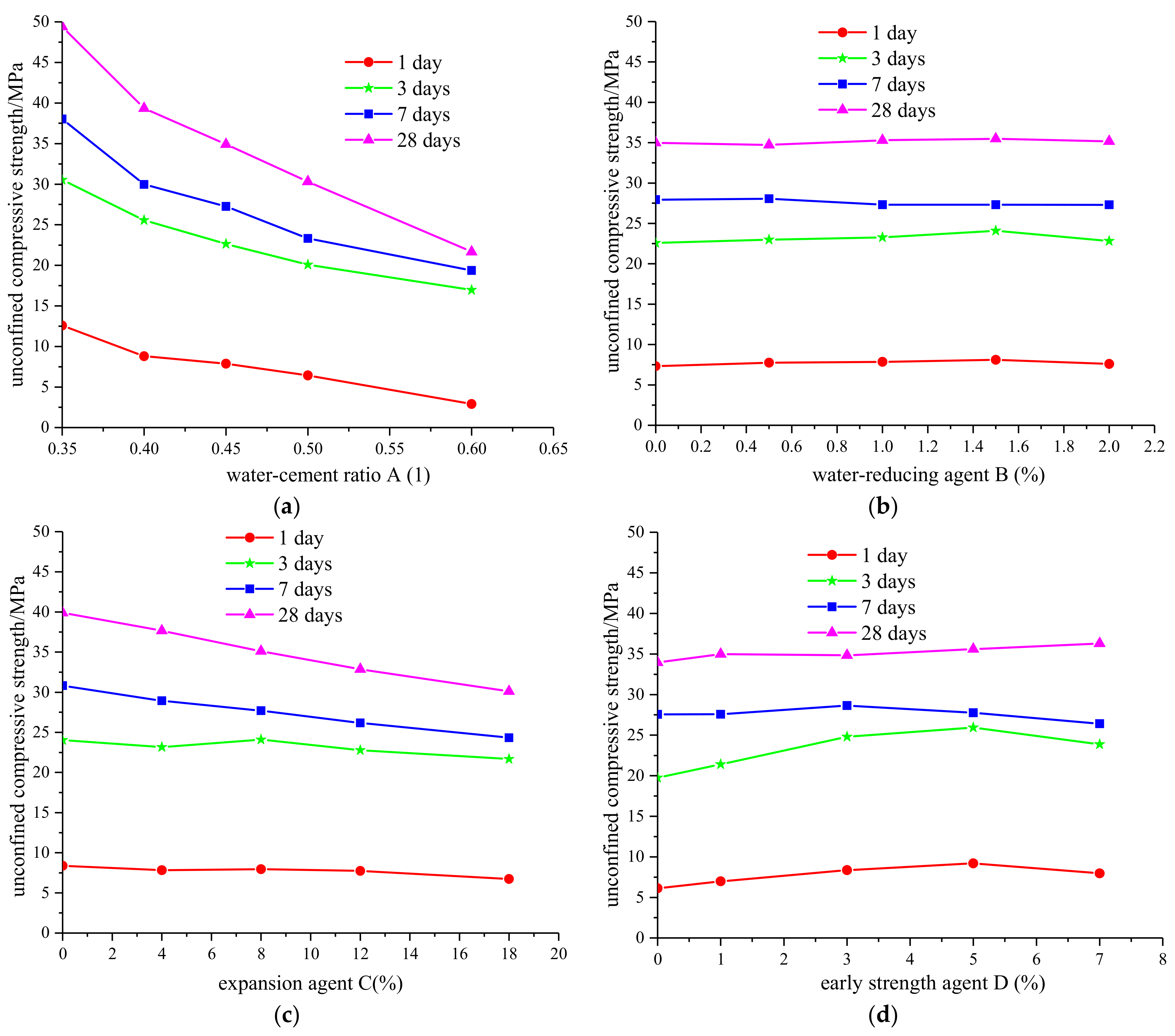
Figure 3a reflects the change law of the compressive strength of the grouting body with the water–cement ratio ranging from 0.35 to 0.6. As the water–cement ratio increased, the strength of the grouting body decreased almost linearly. When the solidification time was less than 1 day, its strength was not high for the insufficient initial setting time. After the solidification time reached 3 days, the compressive strength increased rapidly and was further improved when the solidification time reached 7 days. Compared with the setting time of 3 days, the compressive strength increase rate with a setting time of 7 days or 28 days became slower.
(2)
It can be seen from Figure 3b that the dosage of water-reducing agent had no obvious effect on the strength change of the grouting body.
(3)
Figure 3c reflects the change law of the compressive strength of the grouting body with the percentages of expansion agent content in cement mass ranging from 0% to 18%. The strength of the grouting body dropped rapidly with the increase of the expansion agent content, whose descent rate gradually decreased and was not as large as the corresponding descent rate of the water–cement ratio. The amount of expansion agent was negatively related to the compressive strength and mainly acted in the middle and late stages of the hardening process of the grouting body. The hydration reaction of the expansion agent removed part of the water needed for the cement hydration reaction, disrupting the normal hydration process of cement, which made the water supply for the hydration reaction of the grouting body insufficient, resulting in the strength of the grouting body decreasing, especially in the middle and late stages [29,30,31].
(4)
Figure 3d reflects the change law of the compressive strength of the grouting body with the percentages of early-strength agent content in the cement mass ranging from 0% to 7%. The early-strength agent had the greatest impact on the compressive strength with a setting time of 3 days, followed by 1 day and again after 7 days and had almost no effect on the compressive strength with a setting time of 28 days. When the slurry solidification time was no more than 3 days, the compressive strength gradually increased with the increase of the early-strength agent content and the situation was opposite when the slurry solidification time was over 3 days. When the percentages of early-strength agent content in the cement mass reached 5%, the magnitude of compressive strength reached its peak value. When the percentages of early-strength agent were more than 5%, the improvement of the early strength of the grouting body by increasing the early-strength agent content was poor and even had a negative effect; that is to say, the best percentages of early-strength agent content in cement mass were 5%.
At the initial stage of hydration, the sodium sulfate in the early-strength agent chemically reacted with the main product of cement hydration to form calcium sulfate with greater fineness and better activity, which chemically reacted with calcium aluminate in the cement unceasingly. After a period of chemical reaction, calcium hydroxide was consumed and a large amount of ettringite was generated. The ettringite crystals overlapped each other and were filled with calcium silicate gel, which greatly improved the early strength of the grouting body [32]. When the content of the early-strength agent was higher than the optimal content, the excess early-strength agent molecules chemically reacted with cement hydration reaction products to generate excess ettringite crystals. As a result, the cement stone structure was not enough to resist the expansion pressure generated by a large number of ettringite crystals and the cement stone structure was destroyed. Thus, excessive mixing of early-strength agent causes the strength of the grouting body to decrease [33].

3.1.2. Range Analysis and Variance Calculation of Uniaxial Compressive Strength

The range analysis [24] results of the uniaxial compressive strength of the grouting material under different proportions are shown in Table 3. Kjm is the sum of all test index corresponding to the m-th level of the j-th factor. Kjm is the average value of Kjm and can judge the superiority level of the j-th factor. The range Rj is the range of the j-th factor, i.e., the difference between the maximum and minimum mean of the uniaxial compressive strength under the factor level in column j. The range Rj reflects the fluctuation range of the test index in column j, i.e., the larger the fluctuating value, the greater the influence of the factor level on the test index.
Range analysis is simple, clear and easy to understand, but this method cannot distinguish the fluctuations in the data caused by the test conditions changes or the test errors, and it also cannot give accurate information on the importance of each factor for the test results. Variance analysis [24] can make up for these shortcomings and is usually used to check for the significance of a certain factor. In this paper, the L25 (56) orthogonal table was selected, in which n is the total number of tests, k is the number of columns, r is the number of repetitions at each level and m is the level number of the factor in column j. According to the orthogonal experiment analysis method, it has the following definitions:
T = i = 1 n x i
C = T 2 n
x ¯ = 1 n i = 1 n x i
where x i is the uniaxial compression strength test result and n is the total number of tests.
The degree of freedom d f j of the factor in column j is equal to the number of factor levels m minus 1, that is:
d f j = m 1
From the definition of variance, the calculation formula for the variance M S j of the j-th column is as follows:
M S j = S S j d f j
The F statistic is constructed, the analysis of variance table is calculated and the significance test is performed as follows:
F factor = M S factor M S factor
As shown in Table 4, according to the above calculation, the significance test is performed, and the analysis of variance table is listed.

3.1.3. Synthetic Analysis on Uniaxial Compressive Strength

The range and variance analysis results of the compressive strength of grouting stones at different ratios can be obtained respectively in Table 3 and Table 4, specifically as follows:
(1)
Range and variance analysis for compressive strength under a solidification time of 1 day
The range RA > RD > RC > RB indicates that the influence of the four factors on the compressive strength under a solidification time of 1 day in descending order was water–cement ratio, early-strength agent, expanding agent and water-reducing agent. The water–cement ratio was an important factor, followed by the early-strength agent, while the expansion agent and water-reducing agent had less influence on the first day’s compressive strength. Changing the dosage of the four factors made the compressive strength increase by 331.56%, 10.86%, 14.86% and 50.18% relative to their minimum values, respectively. The influence of factors A and D is highly significant, while the influence of factors B and C is not significant. The optimal level of highly significant factors is A1 (0.35) D4 (5%).
As shown in Table 2 and Table 3 and Figure 3, the compressive strength under a solidification time of 1 day was no more than 13 MPa. Reducing the water–cement ratio significantly improved the compressive strength of the water–cement mixture. The early-strength agent had a positive effect on improving the compressive strength and the best percentage of early-strength agent content in the cement mass was 5%, exceeding which, the expected effect would not be achieved. The effect of the expansion agent on the compressive strength was relatively small, i.e., with the increase of the amount of expansion agent, the compressive strength curve showed a weak downward trend. The water-reducing agent had almost no effect on the first day’s compressive strength.
(2)
Range and variance analysis for compressive strength under a solidification time of 3 days
The range RA > RD > RC > RB indicates that the influence of the four factors on the compressive strength under a solidification time of 3 days in descending order was water–cement ratio, early-strength agent, expanding agent and water-reducing agent. The water–cement ratio was an important factor, followed by the early-strength agent, again after the expansion agent, while the water-reducing agent had less influence on the compressive strength. Changing the dosage of the four factors made the third day’s compressive strength increase by 80.00%, 6.69%, 11.17% and 31.32% relative to their minimum values, respectively. The results of variance analysis show that the influence of factors A and D are highly significant, followed by the factor C, while the influence of factor B is not significant. The optimal level of highly significant factors is A1 (0.35) B1 (0%) C1 (0%) D4 (5%).
As shown in Table 2 and Table 3 and Figure 3, the third day’s compressive strength was significantly improved compared to the first day’s compressive strength. Reducing the water–cement ratio significantly improved the third day’s compressive strength. The early-strength agent had a positive effect on improving the compressive strength of the grouting body on the third day, and the best percentage of early-strength agent content in cement mass was 5%. With the increase of the amount of expansion agent, the compressive strength curve showed a weak downward trend. The water-reducing agent had almost no effect on the first day’s compressive strength.
(3)
Range and variance analysis for compressive strength under a solidification time of 7 days and 28 days
The order of the influence of each factor on the seventh day’s compressive strength was water–cement ratio > expanding agent > early-strength agent > water-reducing agent. The influence of factors A, C and D are highly significant, while the influence of factor B is not significant. When the solidification time of the slurry was between 3 days and 7 days, the influence of the expanding agent on compressive strength was in the second most important position, surpassing the early-strength agent.
The order of the influence of each factor on the 28th day’s compressive strength was water–cement ratio > expanding agent > early-strength agent > water-reducing agent. The influence of factors A and C are highly significant, followed by the factor D, while the influence of factor B is not significant. When the solidification time of the slurry was between 7 days and 28 days, the influence of the expanding agent on compressive strength became bigger and bigger, and the influence of early-strength agent gradually decreased with the passage of time.
As shown in Figure 3, the compressive strength of the grouting stone body decreased with the increase of the water–cement ratio, and its descent speed tended to gradually slow with the increase of the solidification time. The water-reducing agent always had little effect on the compressive strength of the grouting body. The expansion agent had little effect on the compressive strength of the grouting body in the early stage of solidification. With the increase of solidification time, the influence of expansion agent on the strength of the grouting body became greater and greater, and the later compressive strength of the grouting body was inversely proportional to the amount of expansion agent. The effect of the early-strength agent was just opposite to that of the expansion agent, i.e., with the increase of solidification time, its influence on the strength of the grouting body became smaller and smaller. The optimal amount of the early-strength agent was 5%. The compressive strength on the first day and the third day after adding the early-strength agent was increased by 50.18% and 31.32%, respectively.

3.2. Experimental Results for Fluidity

As shown in Figure 1, the friction resistance magnitude of DPC pile retrieved by injecting a water–cement mixture into the pile-soil clearance is closely related to the flow and diffusion effect of the slurry. As an important indicator, the fluidity of the water–cement mixture determines the grouting effect in the pile-soil clearance to a certain extent. Figure 4 shows the influence of various factors on the development trend of fluidity, from which the following can be seen: The fluidity of the water–cement mixture was positively correlated with the water–cement ratio and could be improved significantly by increasing the water–cement ratio. This is because the free water in the water–cement mixture occupied more space with the increasing of the water–cement ratio. Just like the water–cement ratio, the fluidity also showed positive correlation with the dosage of water-reducing agent. This is because the water-reducing agent molecules were oriented and adsorbed on the surface of the cement particles to obtain the same electric charge and generate electrostatic repulsion, which destroyed the flocculation network structure formed between the cement particles and released more free water [34]. However, the fluidity did not always increase with the increase of the water-reducing agent dosage. That is to say, the water-reducing agent dosage had a saturation point (about 1.5%), exceeding which, the effect by increasing the amount of water-reducing agent to enhance the fluidity of the slurry was very limited. At the same time, the water-reducing agent mixed in excessively caused water–cement mixture disintegration, which is unfavorable for the efficient transmission of grouting liquid in the injection pipe. Therefore, the addition of the water-reducing agent should not exceed the safe dosage of 1.5%. The fluidity of the water–cement mixture showed a decreasing trend with the increase of the expansion agent dosage or the early-strength agent dosage. Relatively speaking, the influence of the expansion agent and early-strength agent on the fluid performance of the slurry was far less than that of water–cement ratio and water-reducing agent.
According to the range analysis of the orthogonal test results for fluidity in Table 5 and the saturation point of the water-reducing agent dosage, the advantageous combination for fluidity is A5 (0.6) B5 (1.5%) C1 (0%) D1 (0%). According to range R in Table 5, the four factors all have different degrees of influence on the fluidity of the slurry, the primary and secondary factors of which are water–cement ratio, water-reducing agent, expansion agent and early-strength agent, respectively. Changing the dosage of the four factors increased the liquidity of water–cement mixture by 232.29%, 105.94%, 22.89% and 11.84% relative to their minimum values, respectively.

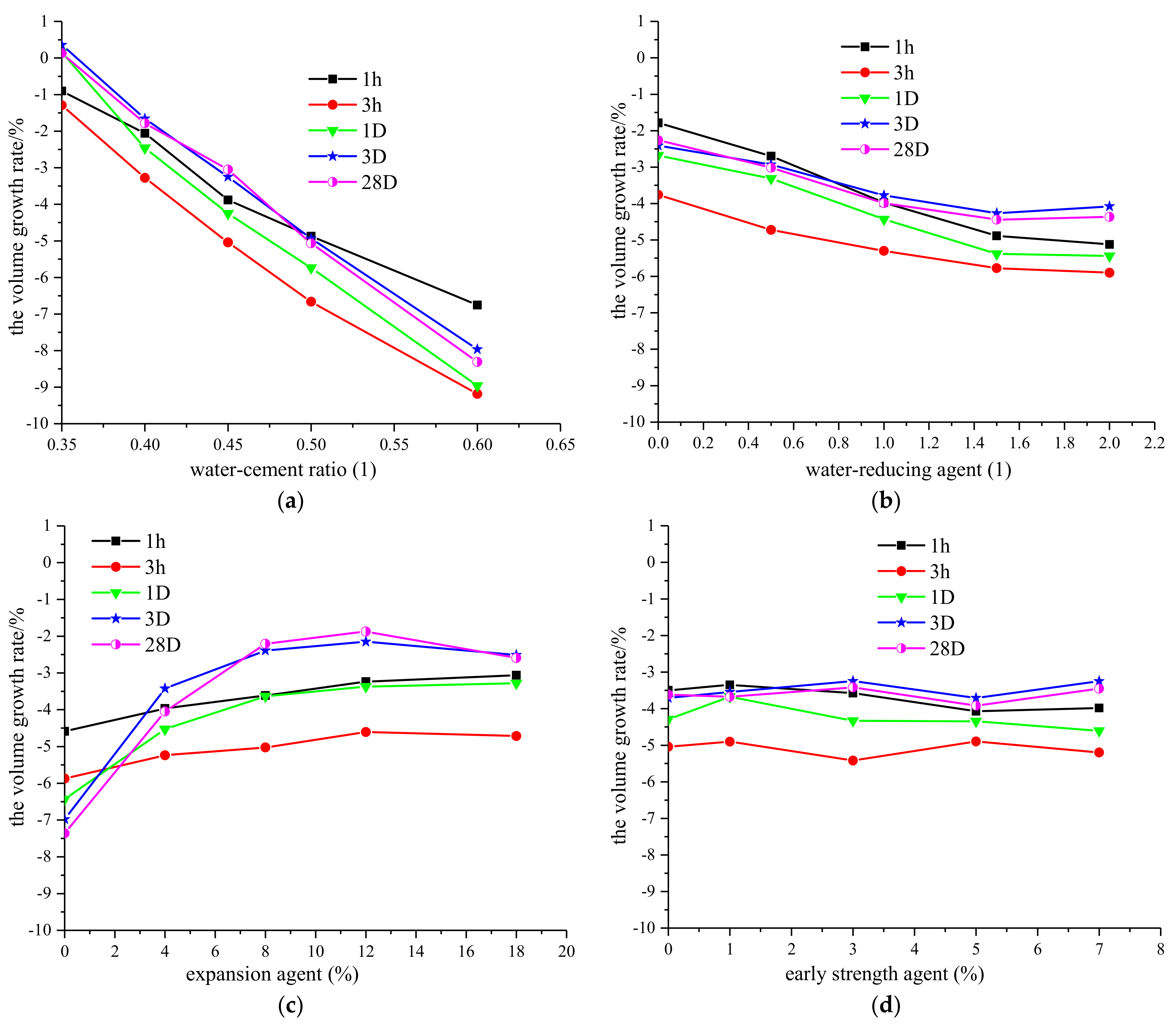
3.3. Experimental Results for the Volume of Grouting Body

The volume of the grouting body formed after water–cement mixture solidification affected the skin friction magnitude of drilling with PHC pipe cased pile. The slight expansion of the grouting body significantly improved the skin friction magnitude. Figure 5 intuitively shows the influence of the four factors on the development trend of the grouting body volume after the grouting liquid was mixed for 1 h, 3 h, 1 day, 3 days and 28 days, respectively, which reflects the bleeding rate and the volume change process of the grouting liquid under the action of multiple factors.
As shown in Figure 5a, the grouting body volume decreased linearly with the increase of the water–cement ratio. As shown in Figure 5b, the grouting body volume decreased rapidly with the increase of the dosage of the water-reducing agent, whose rate of decrease gradually slowed down and was not as large as that of the water–cement ratio. When the dosage of the water-reducing agent exceeded 1.5%, the volume of the grouting body was almost unchanged, which shows that the volume of the grouting body cannot be increased by steadily adding the water-reducing agent after the water-reducing agent has been already added to a certain level. According to Figure 5a,b, the following can be seen: When the mixing time or the solidification time t of the grouting liquid equaled 1 h, the water–cement mixture shrank relative to the original state for bleeding. When t = 3 h, the volume shrinkage of the water–cement mixture reached a minimum for the completion of bleeding. When t = 1 day, the water–cement mixture gradually solidified, during which, the expansion agent played a positive role, resulting in a rapid increase in the volume of the grouting body. At this time, the increment of grouting body with a low water–cement ratio was greater than that of a high water–cement ratio. When t = 3 days, the volume of the grouting body still increased substantially, but the increment of grouting body with low water–cement ratio was less than that of high water–cement ratio. When t = 28 days, the volume of the grouting body hardly changed compared to when the slurry solidification time was 3 days.
By reason of the foregoing, when t was less than 3 days, the volume increment of the grouting body caused by the presence of the expansion agent was less than the volume shrinkage caused by the hardening of the grouting body, thus the volume of the grouting body was in a shrinking state. when t was more than 3 days, the expansion agent played an increasing role, which guaranteed that the volume increment of the grouting body caused by the presence of the expansion agent exceeded or at least equaled the volume shrinkage caused by the hardening of the grouting body. Under these circumstances, the volume of the grouting body was kept in a slightly expanded state, which ensured the friction resistance magnitude and effectively prevented the concrete from cracking.
As shown in Figure 5c, the grouting body volume increased with the increase of the expansion agent content. When t = 1 h or t = 3 h, the volume growth rate of the grouting body was relatively small, which indicates that the expansion effect produced by the expansion agent was far less than the volume shrinkage caused by water separation at the early solidification stage. When t 1 day, the expansion agent gradually reacted with the cement components during the solidification of the water–cement mixture to produce a large amount of swelling crystalline hydrates such as hydrated sulfoaluminate, which, ultimately, led to the increase in the volume of the grouting body as the mixing time or the solidification time t increased. As shown in Figure 5c, the curves of the volume growth rate at the solidification time t = 3 days and t = 28 days almost overlap and show a same law with that of t = 1 day. The volume of the grouting body at t = 3 days or t = 28 days was significantly greater than that of t = 1 day, and the volumes of the grouting body at t = 1 h and t = 3 h were relatively lowest. The above shows that the swelling crystalline hydrates were mainly generated between t = 3 h and t = 3 days; that is to say, at these stages, the expansion agent played an increasing role. When t is more than 3 days, although the effect of the swelling agent was weakened, the swelling agent guaranteed that the volume increment of the grouting body caused by the presence of the expansion agent exceeded or at least equaled the volume shrinkage caused by the hardening of the grouting body. As shown in Figure 5c, the volume of the grouting body first increased and then decreased with the increase of the expansion agent content, i.e., when the dosage of the expansion agent exceeded 12%, the volume of the grouting body was almost unchanged. Thus, the volume of the grouting body could not be increased by steadily adding the expansion agent after the expansion agent had been added to a certain level, i.e., the optimum amount of expansion agent was 12%.
As shown in Figure 5d, the dosage of the early-strength agent had no obvious effect on the volume growth rate of the grouting body.
Table 6 shows the range analysis of the orthogonal test results for the volume growth rate of the grouting body corresponding to the curing time of 1 h, 3 h, 1 day, 3 days and 28 days, respectively. When t = 1 h, changing the dosage of the four factors made the volume growth rate of the grouting body increase by 648.05%, 186.76%, 49.81% and 21.57% relative to their minimum values, respectively. When t = 3 h, changing the dosage of the four factors made the volume growth rate of the grouting body increase by 611.87%, 56.89%, 27.49% and 10.72% relative to their minimum values, respectively. Both when t = 1 h or t = 3 h, range RA > RB > RC > RD indicates that the influence of the four factors on the volume growth rate of the grouting body in descending order was water–cement ratio, water-reducing agent, expansion agent and early-strength agent. According to the results of variance analysis, the water–cement ratio and water-reducing agent are highly significant factors, the expansion agent is a significant factor and the early-strength agent is an insignificant factor. When t = 1 day, t = 3 days and t = 28 days, range RA > RC > RB > RD indicates that the influence of the four factors on the volume growth rate of the grouting body in descending order was water–cement ratio, expansion agent, water-reducing agent and early-strength agent. According to the results of the variance analysis, the water–cement ratio, expansion agent and water-reducing agent are highly significant factors and the early-strength agent is an insignificant factor. In a word, the water–cement ratio is always the greatest influencing factor on the volume growth rate of the grouting body, followed by the water-reducing agent and the expansion agent; the dosage of the early-strength agent has almost no obvious effect. In addition, the influence of the expansion agent on the volume growth rate gradually exceeded that of the water-reducing agent with the increase of time, indicating that the water-reducing agent and the expansion agent mainly play a key role in the bleeding stage and in the solidification stage of the slurry, respectively.

4. The Proportional Optimization Design of Water–Cement Mixture

The previous research results show that the difference in the grouting effect of DPC piles can lead to a difference of more than 39.80% in the frictional resistance of the pile shaft [4]. The ultra-high fluidity can ensure the flow and diffusion effect of the water–cement mixture in the long and narrow pile-soil clearance and, ultimately, determine the magnitude of the lateral pile skin friction. The grouting of DPC piles puts forward higher requirements on the bleeding rate (i.e., the volume growth rate of the grouting body, corresponding to the curing time of 3 h) of the water–cement mixture. That is to say, the smaller the bleeding rate of the slurry, the more the pile-soil clearance will be filled and the greater the frictional resistance formed after grouting. Additionally, the grouting of DPC piles puts forward higher requirements on the early volume of the grouting body, corresponding to the curing time of 1 day. That is to say, in order to prevent the shrinkage of the hole wall from releasing the surrounding soil pressure around the pile shaft and ensure the friction resistance is not reduced, the volume of the early grouting body (such as the grouting body being cured for 1 day) should be characterized by expansion properties. In order to shorten the construction period and ensure that large equipment can move normally on the foundation, the grouting body should be characterized by a higher early strength (such as the grouting body being cured for 3 days). At the same time, in order to ensure the long-term bearing performance and friction resistance of the pile foundation, the grouting body should be characterized by a higher long-term strength (such as the grouting body being cured for 28 days). By reason of the foregoing, the fluidity, the volume growth rate of the grouting body corresponding to the curing time of 3 h and 1 day and the compressive strength with a setting time of 3 days and 28 days have been selected as the experimental index for orthogonal tests. As shown in Table 7, the influence of the four factors on each experimental index in descending order and the optimal combination can be obtained by comparing and analyzing the corresponding range analysis and variance analysis results. In order to determine the proportion of water–cement mixture, the influence of the four factors should be evaluated comprehensively for the optimal combinations because the selected experimental indexes are inconsistent.
Optimal selection for water-reducing agent (factor B): The main purpose of adding a water-reducing agent is to improve the fluidity and to reduce the bleeding rate of the water–cement mixture. For drilling with PHC pipe cased pile, the purpose of improving the fluidity is the primary purpose and task. Therefore, the superiority level for water-reducing agent is taken as B4.
Optimal selection for water–cement ratio (factor A): Optimal selection for water–cement ratio is the most important for the influence of the water–cement ratio on the five experimental indexes compared with the other three factors. If the water–cement ratio A is selected as A5, the fluidity of the slurry can reach the highest value, but the value of the other experimental indexes can reach the smallest value and is detrimental to the formation of skin friction. If the water–cement ratio A is selected as A1, all experimental indexes except the fluidity can reach their highest values, but the value of fluidity is reduced by 69.91% relative to its maximum value. Grouting experience stipulates that the fluidity of the grout should not be less than 25 cm. Therefore, the choice of the value of water–cement ratio should be infinitely close to A5 while meeting the rule of field experience. After comprehensive analysis, when B = B4, according to Figure 4, the water–cement ratio A can be selected as A3 to ensure that the fluidity of the grout is not less than 25cm and the value of water–cement ratio is infinitely close to A5.
Optimal selection for expansion agent (factor C): Compared with other factors, factor C ranks third and is a secondary factor for the influence on the fluidity, the volume growth rate of the grouting body corresponding to the curing time of 3 h and the compressive strength with a setting time of 3 days. However, for the volume growth rate of the grouting body corresponding to the curing time of 1 day and the compressive strength with a setting time of 28 days, factor C ranks second and is a key factor. Thus, factor C can be primarily selected as C1 or C4. When C = C1, the volume growth rate of the grouting body corresponding to the curing time of 1 day is reduced by 47.59% compared to C = C4. When C = C4, the compressive strength with a setting time of 28 days is reduced by17.63% compared to C = C1. After comprehensive analysis, the expansion agent is taken as C4.
Optimal selection for early-strength agent (factor D): According to Table 7, after comprehensive analysis, the early-strength agent is taken as D4.
In summary, through the analysis of the comprehensive balance method, it can be concluded that the optimal combination of grouting material for drilling with PHC pipe cased pile is A3B4C4D4. That is to say that the water–cement ratio is 0.45, the dosage of the 4% water-reducing agent mother liquor accounts for 1.5% of the cement mass, the dosage of expansion agent accounts for 12% of cement mass and the dosage of early-strength agent accounts for 5% of cement mass, respectively.

5. Conclusions

(1)
The strength of the grouting body decreases linearly with the increase of the water–cement ratio, and the dosage of water-reducing agent has no obvious effect on the strength. As the dosage of the expansion agent increases, the strength of the grouting body decreases rapidly. The expansion agent mainly acts in the middle and late stages of the hardening process of the grouting material.
(2)
The early-strength agent has the greatest influence on the strength of the grouting body when it has been solidified for 3 h, followed by 1 day and again after 7 days and has almost no effect on the compressive strength when the grout curing time is 28 days.
(3)
When the grout curing time is 3 h, the optimal dosage of the early-strength agent is 5%. Excessive mixing of the early-strength agent is easy to chemically react with cement molecules to generate ettringite crystals, thereby destroying the structure of the grouting body and causing the strength of the grouting body to decrease.
(4)
Expansion agents have little effect on the compressive strength in the early stage but have a greater effect on the strength in the later stage. The compressive strength in the later stage is inversely proportional to the amount of expansion agent. Early-strength agents have a greater impact on the early strength but less on the later strength. The compressive strength on the first day and the third day after adding the early-strength agent was increased by 50.18% and 31.32%, respectively, which can significantly shorten the construction period.
(5)
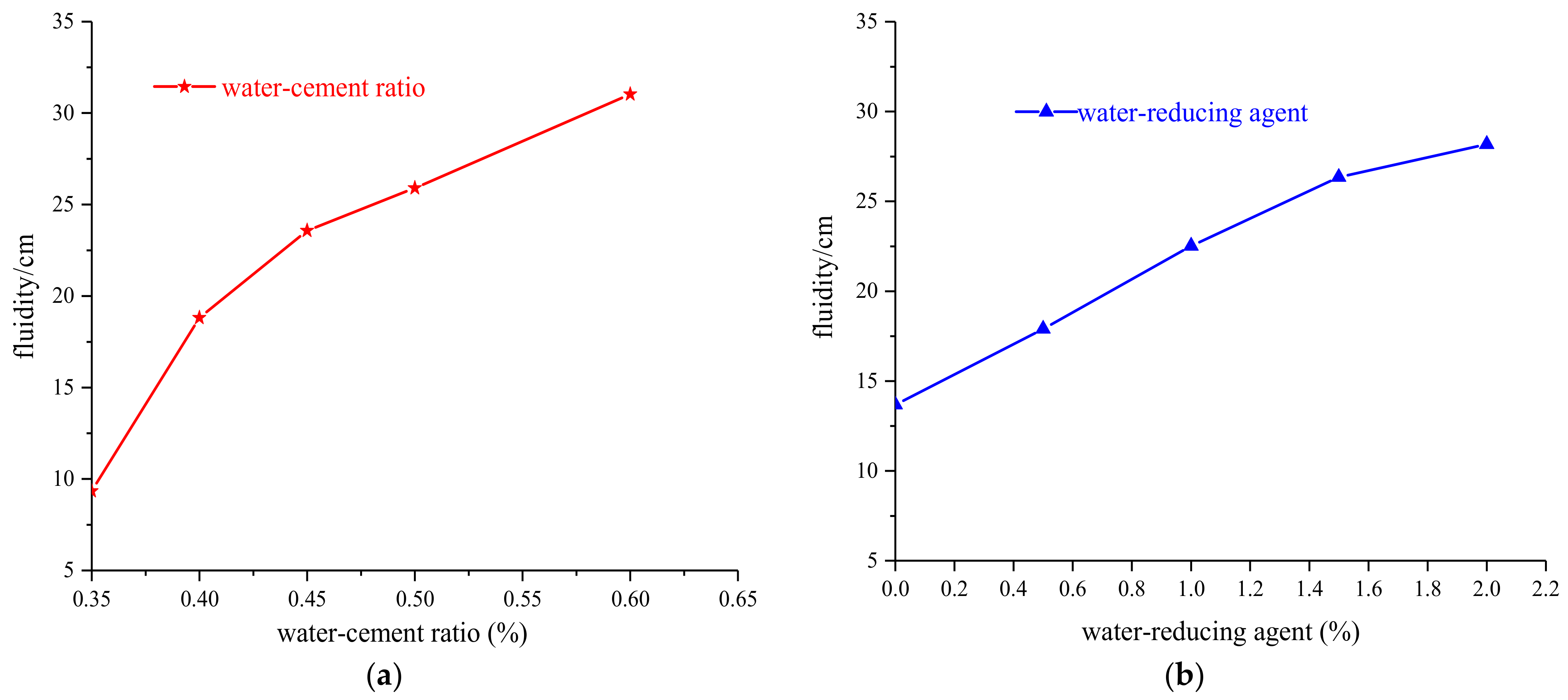
The fluidity of the water–cement mixture can be improved significantly by increasing the water–cement ratio. The water-reducing agent dosage has a saturation point (about 1.5%), exceeding which, the effect of increasing the amount of water-reducing agent to enhance the fluidity of the slurry will be very limited. The fluidity of water–cement mixture shows a decreasing trend with the increase of the expansion agent dosage or the early-strength agent dosage.
(6)
The grouting body volume decreases linearly with the increase of the water–cement ratio and decreases rapidly with the increase of the dosage of the water-reducing agent. The volume of the grouting body cannot be increased by steadily adding the water-reducing agent after the water-reducing agent has been already added to a certain level.
(7)
When the solidification time is more than 3 days, the expansion agent plays an increasing role, which can guarantee that the volume increment of the grouting body caused by the presence of the expansion agent exceeds or at least equals the volume shrinkage caused by the hardening of the grouting body.
(8)
The water–cement ratio is always the greatest influencing factor on the volume growth rate of the grouting body, followed by the water-reducing agent and the expansion agent; the dosage of the early-strength agent has almost no obvious effect. The water-reducing agent and the expansion agent mainly play a key role in the bleeding stage and in the solidification stage of the slurry, respectively.
(9)
The optimal combination of grouting material for drilling with PHC pipe cased pile is A3B4C4D4. That is to say that the water–cement ratio is 0.45, the dosage of the 4% water-reducing agent mother liquor accounts for 1.5% of the cement mass, the dosage of expansion agent accounts for 12% of the cement mass and the dosage of early-strength agent accounts for 5% of cement mass, respectively.

Author Contributions

Z.H. organized the outline and the whole contents, and implemented the data analysis; M.T. put forward the ideas and theoretical model; S.L. revised the manuscript; Y.Z. designed the experiment and performed the remote data collection. All authors have read and agreed to the published version of the manuscript.

Funding

This research was funded by the National Natural Science Foundation of China (grant number 52078142); the Science and Technology Program of Guangzhou, China (grant number 202002030194); the National Key Research and Development Program of China (2018YFC1504903); the Guangdong Basic and Applied Basic Research Foundation (2019A1515110836); and the Open Research Fund of State Key Laboratory of Geomechanics and Ge-otechnical Engineering, Institute of Rock and Soil Mechanics, Chinese Academy of Sciences (Z019018).

Institutional Review Board Statement

Not applicable.

Informed Consent Statement

Not applicable.

Data Availability Statement

Data is contained within the article.

Conflicts of Interest

The authors declare no conflict of interest.

References

  1. Tang, M.; Hu, H.; Cui, J.; Yang, X.; Hu, H.; Chen, H. The Vertical Bearing Mechanism of Hybrid Bored Pre-stressed Concrete Cased Piles. Int. J. Civ. Eng. 2020, 18, 293–302. [Google Scholar] [CrossRef]
  2. Hou, Z.; Tang, M.; Hu, H.; Lin, Z.; Chen, Y.; Zhao, S.; Zhang, S. A new type of PHC pile-sinking technology: Drilling with PHC Pipe Cased Pile and its development directions. IOP Conf. Ser. Earth Environ. Sci. 2020, 580, 012013. [Google Scholar] [CrossRef]
  3. Yang, X. Experimental Study on Vertical Compressive Bearing Capacity and Seismic Performance of Drilling with Large Diameter PHC Pipe Cased Pile. Master’s thesis, Guangzhou University, Guangzhou, China, 2018. [Google Scholar]
  4. Hou, Z.; Tang, M.; Hu, H.; Li, J.; Zhang, S.; Xu, X.; Liu, C. Comparative study on the vertical load-bearing capacity of the drilling with pre-stressed concrete pipe cased pile based on in-situ and physical simulation tests. Rock Soil Mech. 2021, 42, 419–429. [Google Scholar]
  5. Zhang, C.; Yang, J.S.; Xie, Y.P.; Gong, F.H.; Liang, X.; Lei, J.S.; Su, B.Z. Experiment and application for grouting materials for karst under conditions of underground water flow before shield tunneling. Chin. J. Rock Mech. Eng. 2018, 37, 133–143. [Google Scholar]
  6. Rickstal, F.V. Grout Injection of Masonry, Scientific Approach and Modeling. Ph.D. Thesis, Katholieke Universiteit, Leuven, Belgium, 2000. [Google Scholar]
  7. Yuan, B.; Li, Z.; Zhao, Z.; Ni, H.; Su, Z.; Li, Z. Experimental study of displacement field of layered soils surrounding laterally loaded pile based on Transparent Soil. J. Soils Sediments 2021, 21, 3072–3083. [Google Scholar] [CrossRef]
  8. Du, Y.; Pei, X.; Huang, R.; He, Z.; Zhang, J. Study on flow characteristics and application of viscosity time-varying grouting material. Rock Soil Mech. 2017, 38, 3498–3504. [Google Scholar]
  9. Guo, Y. Study of Mechanical Model of Reinforced Soil by Pregrouting and Its Application in Tunnel Practices. Doctoral Thesis, Beijing Jiaotong University, Beijing, China, 2016. [Google Scholar]
  10. Baltazar, L.G.; Henriques, F.M.A.; Jorne, F. Optimisation of flow behaviour and stability of superplasticized fresh hydraulic lime grouts through design of experiments. Constr. Build. Mater. 2012, 35, 838–845. [Google Scholar] [CrossRef]
  11. Pei, X.; Huang, R.; Li, Z.; Luo, J. Research on grouting reinforcement of unloading fractured loose rock mass in left bank of jinping I hydropower station. Chin. J. Rock Mech. Eng. 2011, 30, 284–288. [Google Scholar]
  12. He, Z. Study on Test and Operation Mechanism of the Watertight and Water Shut-Off Grout in Fractured Rock Mass. Doctoral Thesis, Central South University, Changsha, China, 2007. [Google Scholar]
  13. Yun, J.W.; Park, J.J.; Kwon, Y.S.; Kim, B.K.; Lee, I.M. Cement-based fracture grouting phenomenon of weathered granite soil. KSCE J. Civ. Eng. 2016, 21, 232–242. [Google Scholar] [CrossRef]
  14. Zhang, C.; Yang, J.S.; Ye, X.T.; Zhang, Y.; Zhang, Z.B.; Su, B.Z. Experiment and application research on stability performance of filling grouting slurry. Chin. J. Rock Mech. Eng. 2018, 37, 3604–3612. [Google Scholar]
  15. Dreese, T.L.; Wilson, D.B.; Heenan, D.M.; Cockburn, J. State of the Art in Computer Monitoring and Analysis of Grouting. In Proceedings of the Third International Conference on Grouting and Ground Treatment, New Orleans, LA, USA, 10–12 February 2003. [Google Scholar]
  16. Karol, R.H. Chemical Grouting and Soil Stabilization, 3rd ed.; Marcel Dekker, Inc.: New York, NY, USA, 2003. [Google Scholar]
  17. Wang, Q.; Qu, L.; Guo, H.; Wang, Q. Grouting reinforcement technique of qingdao jiaozhou bay subsea tunnel. Chin. J. Rock Mech. Eng. 2011, 30, 790–802. [Google Scholar]
  18. Sui, W.; Liu, J.; Hu, W.; Qi, J.; Zhan, K. Experimental investigation on sealing efficiency of chemical grouting in rock fracture with flowing water. Tunn. Undergr. Space Technol. 2015, 50, 239–249. [Google Scholar] [CrossRef]
  19. Hou, Z.; Tang, M.; Hu, H.; Lin, Z.; Chen, H.; Liu, C. Quantitative Characterization of Grouting Stones for Drilling with Pre-stressed Concrete Pile Cased Pile. IOP Conf. Ser. Earth Environ. Sci. 2021, 632, 022008. [Google Scholar] [CrossRef]
  20. Hou, Z.; Tang, M.; Hu, H.; Liu, C.; Su, D. Physical model tests on bearing performance of drilling pre-stressed concrete pile cased pipe-cased pile considering hole collapse. Chin. J. Rock Mech. Eng. 2022, 44, 1–10. [Google Scholar]
  21. Jiang, L.; Yan, B.; Xiao, Z.; Wang, W.; Zhang, D. GB175—2007, General Portland Cement, Interpretation of standard provisions. Cement 2008, 4, 2. [Google Scholar]
  22. Ministry of Housing and Urban-Rural Development of the People’s Republic of China. JGJ/T344-2014 Technical Specification for Pile While Drilling; China Construction Industry Press: Beijing, China, 2014. [Google Scholar]
  23. Wu, S. Test and Numerical Analysis of the Vertical Compressive Bearing Performance of Large Diameter Core-filled Pipe Piles While Drilling. Master’s thesis, Guangzhou University, Guangzhou, Chin, 2019. [Google Scholar]
  24. Li, Z.; Du, S. Experimental Optimization Design and Statistical Analysis; Science Press: Beijing, China, 2010. [Google Scholar]
  25. Zhang, C.; Liang, J.-W.; Yang, J.-S.; Zhang, G.-J.; Xie, Y.-P.; Ye, X.-T. Sealing mechanism of slurry materials considering temporal and spatial variation of viscosity. Chin. J. Geotechnol. Eng. 2019, 5, 2130–2139. [Google Scholar]
  26. National Bureau of Quality and Technical Supervision of the People’s Republic of China. GB/T 17671-1999 Cement Mortar Strength Inspection Method (ISO Law); China Construction Industry Press: Beijing, China, 1999. [Google Scholar]
  27. General Administration of Quality Supervision, Inspection and Quarantine of the People’s Republic of China. GBT-2419-2005 Cement Mortar Fluidity Determination Method Specification; China Construction Industry Press: Beijing, China, 2005. [Google Scholar]
  28. Yang, X.; Peng, C.; Jiang, Y. Guidelines for Testing Granular Grouting Materials; New Century Press: Beijing, China, 2010. [Google Scholar]
  29. Peng, C.; Geng, C.; Liu, Y.; Shi, H.; Yu, S.; Ding, Q. Effect of expansion agent and pottery sand on UHPC anti-wear performance and volume stability. Bull. Chin. Ceram. Soc. 2020, 39, 1132–1139. [Google Scholar]
  30. Hu, S.; Lu, L.; He, Y.; Li, Y.; Ding, Q. The hydration of blended cement at low W/B ratio. J. Wuhan Univ. Technol. Mater 2003, 18, 72–75. [Google Scholar]
  31. Wang, H. Research on application of anti-scouring admixture in hydraulic concrete. China Concr. Cem. Prod. 2008, 4, 20–22. [Google Scholar]
  32. Shi, H.; Sun, Z.; Deng, K. Encyclopedia of Concrete Admixture Technology; Chemical Industry Press: Beijing, China, 2013. [Google Scholar]
  33. Wu, Y.; Liu, D. Effect of early strength agents on early performance of composite foamed lightweight concrete. China Concr. Cem. Prod. 2016, 35, 3351–3356. [Google Scholar]
  34. Sheng, Y.; Li, G.; Jiang, H. Effects of superplasticizers and fly ash on rheological properties of cemented tailings backfill. J. Chongqing Univ. 2020, 43, 55–64. [Google Scholar]
Figure 1. Physical diagrams of the orthogonal test. (a) Uniaxial compressive strength test; (b) fluidity test; (c) volume growth rate of the grouting body test.
Crystals 12 00010 g001
Figure 2. Physical diagrams of the orthogonal test. (a) Uniaxial compressive strength test; (b) fluidity test; (c) volume growth rate of the grouting body test; (d) Schematic diagram of the volume growth rate of the grouting body test.
Crystals 12 00010 g002
Figure 3. The influence of various factors on the development trend of compressive strength. (a) Influence of water–cement ratio on compressive strength; (b) influence of water-reducing agent on compressive strength; (c) influence of expansion agent on compressive strength; (d) influence of early-strength agent on compressive strength.
Crystals 12 00010 g003
Figure 4. The influence of various factors on the development trend of fluidity. (a) Influence of water–cement ratio on fluidity; (b) influence of water-reducing agent on fluidity; (c) influence of expansion agent on fluidity; (d) influence of early-strength agent on fluidity.
Crystals 12 00010 g004aCrystals 12 00010 g004b
Figure 5. The influence of various factors on the volume growth rate of the grouting body corresponding to the curing time of 1 h, 3 h, 1 day, 3 days and 28 days, respectively. (a) Influence of water–cement ratio on the volume growth rate; (b) influence of water-reducing agent on the volume growth rate; (c) influence of expansion agent on the volume growth rate; (d) influence of early-strength agent on the volume growth rate.
Crystals 12 00010 g005
Table 1. Head design of orthogonal tests.
LevelInfluencing Factor
Water–Cement Ratio AWater-Reducing Agent BExpansion
Agent C
Early-Strength Agent D
10.350.00%0%0%
20.400.50%4%1%
30.451.00%8%3%
40.501.50%12%5%
50.602.00%18%7%
Table 2. Orthogonal tests scheme and test results.
NumberWater–Cement RatioWater-Reducing AgentExpansion AgentEarly-Strength AgentBlank ColumnBlank ColumnUnconfined Compressive Strength
/MPa
ABCDEF1 Day3 Days7 Days28 Days
S10.350.0%0%0%1110.6327.2141.6953.04
S20.350.5%4%1%2211.4228.1040.1251.70
S30.351.0%8%3%3313.5132.9838.7549.29
S40.351.5%12%5%4415.0135.1036.3247.46
S50.352.0%18%7%5512.3529.2433.2445.56
S60.40.0%4%3%459.4527.0132.1841.61
S70.40.5%8%5%5110.6328.9930.9239.47
S80.41.0%12%7%128.4125.5727.4537.91
S90.41.5%18%0%236.1521.7026.2433.62
S100.42.0%0%1%349.3924.5333.0644.13
S110.450.0%8%7%248.3424.2326.7236.12
S120.450.5%12%0%356.8918.0226.1331.86
S130.451.0%18%1%416.0619.9623.4430.24
S140.451.5%0%3%529.4725.7331.6839.15
S150.452.0%4%5%138.6625.2528.3837.25
S160.50.0%12%1%535.3417.6122.1826.98
S170.50.5%18%3%146.3120.6421.7823.93
S180.51.0%0%5%258.8623.5026.2736.59
S190.51.5%4%7%317.1821.1223.3335.28
S200.52.0%8%0%424.5317.4823.0528.82
S210.60.0%18%5%322.8216.8316.9417.19
S220.60.5%0%7%433.5519.2121.3626.61
S230.61.0%4%0%542.4214.3320.6822.48
S240.61.5%8%1%152.7416.8019.0621.88
S250.62.0%12%3%213.0517.6118.8320.14
Table 3. Range analysis of orthogonal test results for compressive strength /MPa.
DaysNumberWater–Cement Ratio AWater-Reducing Agent BExpansion Agent CEarly-Strength Agent DBlank Column EBlank Column FPrimary and Secondary Factors
1 dayK112.587.318.386.127.357.51Water–cement ratio > early-strength agent > expansion agent > water-reducing agent
K28.87.767.836.997.567.33
K37.887.857.958.367.967.44
K46.448.117.749.197.728.29
K52.927.596.747.978.048.06
Range R9.670.791.643.070.690.96
3 daysK130.5322.5824.0419.7523.0922.98Water–cement ratio > early-strength agent > expansion agent > water-reducing agent
K225.5622.9923.1621.423.0322.74
K322.6423.2724.124.822.723.35
K420.0724.0922.7825.9323.7523.77
K516.9622.8221.6823.8723.1822.91
Range R13.571.512.426.181.061.02
7 daysK138.0227.9430.8127.5627.6727.64Water–cement ratio > Expansive agent > Early-strength agent > Water-reducing agent
K229.9728.0628.9427.5727.6327.85
K327.2727.3227.728.6427.6427.38
K423.3227.3326.1827.7727.2727.71
K519.3727.3124.3326.4227.7427.38
Range R18.650.756.482.220.470.47
28 daysK149.4134.9939.933.9634.835.64Water–cement ratio > Expansive agent > Early-strength agent > Water-reducing agent
K239.3534.7137.6634.9835.6334.95
K334.9235.335.1134.8335.5534.75
K430.3235.4832.8735.5934.9534.82
K521.6635.1830.1136.334.7335.5
Range R27.750.769.82.330.90.89
Table 4. Variance analysis of compressive strength orthogonal test results (1, 3, 7, 28 days).
Sources of VariationCompressive Strength for 1 DayCompressive Strength for 3 DaysCompressive Strength for 7 DaysCompressive Strength for 28 Days
Square DeviationF-
Value
SignificanceSquare DeviationF-
Value
SignificanceSquare DeviationF-
Value
SignificanceSquare DeviationF-ValueSignificance
water–cement ratio A61.9795.59**135.38171.99**250.451288.98**532.96612.88**
water-reducing agent B0.440.68 1.692.15 0.713.63 0.430.50
expansion agent C1.842.83 4.996.34*31.04159.74**74.4385.59**
early-strength agent D7.1611.04**32.0140.67**3.1416.14**3.814.38*
FαF0.05(4,8) = 3.84; F0.01(4,8) = 7.01
annotation*: significant; **: highly significant.
Table 5. Range analysis of orthogonal test results for fluidity/cm.
NumberWater–Cement RatioWater-Reducing AgentExpansion AgentEarly-Strength AgentBlank ColumnBlank Column
ABCDEF
K1(K1j)46.6968.43120.72116.40111.48111.06
K2(K2j)94.0789.52116.36110.49108.81110.10
K3(K3j)117.86112.63104.58107.13107.21109.61
K4(K4j)129.50131.7798.24104.07107.37106.15
K5(K5j)155.16140.94103.38105.19108.41106.38
K19.3413.6924.1423.2822.3022.21
K218.8117.9023.2722.1021.7622.02
K323.5722.5320.9221.4321.4421.92
K425.9026.3519.6520.8121.4721.23
K531.0328.1920.6821.0421.6821.28
Range R21.6914.504.502.470.850.98
Primary and secondary factors (fluidity): Water–cement ratio > water-reducing agent > expansion agent > early-strength agent
Table 6. Range analysis of orthogonal test results for the volume growth rate of the grouting body corresponding to the curing time of 1 h, 3 h, 1 day, 3 days and 28 days, respectively.
Curing TimeNumberWater–Cement RatioWater-Reducing AgentExpansion AgentEarly-Strength AgentBlank ColumnBlank ColumnTest Results
ABCDEF
1 h001−0.90−1.79−4.59−3.50−3.60−3.41Primary and secondary factors: Water–cement ratio > water-reducing agent > expansion agent > early-strength agent
K2−2.06−2.70−3.97−3.35−3.46−3.95
K3−3.88−3.97−3.61−3.57−3.93−3.40
K4−4.87−4.89−3.24−4.07−3.63−3.65
K5−6.75−5.12−3.06−3.98−3.85−4.06
Range R5.853.341.530.720.470.67
3 hK1−1.29−3.76−5.87−5.04−5.12−5.17Primary and secondary factors: Water–cement ratio > water-reducing agent > expansion agent > early-strength agent
K2−3.28−4.72−5.24−4.90−4.83−5.38
K3−5.04−5.30−5.03−5.42−5.26−4.84
K4−6.66−5.77−4.61−4.89−5.12−4.70
K5−9.19−5.90−4.71−5.20−5.12−5.37
Range R7.902.141.270.520.440.68
1 dayK10.16−2.68−6.43−4.29−4.17−3.96Primary and secondary factors: Water–cement ratio > expansion agent >water-reducingagent > early-strength agent
K2−2.46−3.31−4.53−3.67−4.19−4.08
K3−4.25−4.43−3.63−4.33−4.31−4.45
K4−5.74−5.38−3.37−4.34−4.20−4.08
K5−8.96−5.44−3.28−4.61−4.38−4.67
Range R9.122.763.150.930.210.71
3 daysK10.36−2.41−6.98−3.71−3.55−3.28Primary and secondary factors: Water–cement ratio > expansion agent > water-reducing agent > early-strength agent
K2−1.66−2.93−3.42−3.54−3.17−3.11
K3−3.25−3.77−2.39−3.25−3.39−3.61
K4−4.94−4.27−2.15−3.71−3.45−3.61
K5−7.97−4.08−2.51−3.25−3.88−3.85
Range R8.321.864.830.460.710.73
28 dayK10.13−2.26-7.36−3.62−3.85−3.82Primary and secondary factors: Water–cement ratio > expansion agent > water-reducing agent > early-strength agent
K2−1.78−3.02−4.05−3.68−3.85−3.44
K3−3.05−3.99−2.21−3.42−3.57−3.98
K4−5.07−4.44−1.87−3.92−3.45−3.73
K5−8.31−4.37−2.59−3.45−3.36−3.11
Range R8.442.185.490.500.490.87
Table 7. The influence of four factors on each experimental index in descending order and the optimal combination.
Experimental IndexPrimary and Secondary FactorsOptimal Combination
① the fluidityA > B > C > DA5B4C1D1
② the volume growth rate of the grouting body corresponding to the curing time of 3 hA > B > C > DA1B1C1D1
③ the compressive strength with a setting time of 3 daysA > D > C > BA1B1C1D4
④ the compressive strength with a setting time of 28 days A > C > D > BA1B1C1D1
⑤ the volume growth rate of the grouting body corresponding to the curing time of 1 dayA > C > B > DA1B1C4D1
Publisher’s Note: MDPI stays neutral with regard to jurisdictional claims in published maps and institutional affiliations.

