Article

Oxidation Behavior of FeCoNiCrMo High-Entropy Coatings by Atmospheric Plasma Spraying on Zircaloy-4 in Steam at 1100 °C

1
Faculty of Materials Science and Engineering, Kunming University of Science and Technology, Kunming 650093, China
2
Faculty of Civil Aviation and Aeronautics, Kunming University of Science and Technology, Kunming 650500, China
*
Author to whom correspondence should be addressed.
Crystals 2022, 12(11), 1529; https://doi.org/10.3390/cryst12111529
Submission received: 28 September 2022 / Revised: 17 October 2022 / Accepted: 20 October 2022 / Published: 27 October 2022
(This article belongs to the Special Issue Advances in Zr-Based Alloys)

Abstract

:
As a potential accident-tolerant fuel cladding material, we studied the method of preparing FeCoNiCrMo coatings on zircaloy-4 substrates by atmospheric plasma spraying (APS) technology to explore the high-temperature oxidation behavior of the FeCoNiCrMo coatings at 1100 °C in high-temperature steam. Various surface analysis techniques such as X-ray diffraction, electron probe microanalysis, and scanning electron microscopy were used to analyze the phase composition and microstructure of the oxidized products. The oxidation behavior of the FeCoNiCrMo coatings and the diffusion of the FeCoNiCrMo coatings to the zircaloy-4 substrates were analyzed. After oxidation at 1100 °C, a dense Cr2O3 oxide layer was formed on the coating’s surface, which grew from 1.5 to 3 μm after 15 to 60 min of oxidation, and the FeCoNiCrMo coatings and the substrates diffused simultaneously. The oxidation tests showed that the FeCoNiCrMo coatings prepared by APS can effectively delay the oxidation of zircaloy-4 substrates.

1. Introduction

The nuclear accident at the Fukushima Daiichi nuclear power plant in 2011 drew worldwide attention to reactor safety in the event of an accident [1,2]. Zircaloy-4 is widely used as nuclear fuel cladding material due to its low neutron absorption cross-section, good wear resistance, and corrosion resistance in light-water reactors [1,2,3,4]. However, it is particularly important for the zircaloy-4 to find coatings with excellent properties. In the case of a loss-of-coolant accident (LOCA), zircaloy-4 will react with water and produce large amounts of hydrogen gas and then resulting in the hydrogen gas to explod. And finally lead to a large amount of radioactive material leakage. Therefore, accident-tolerant fuel (ATF) has been widely studied as a material to resist beyond-design-basis (BDB) accidents in nuclear power plants. One of the core tasks for which it was designed was to develop cladding materials with excellent performances. The cladding should have good resistance to radiation and corrosion, a relatively small neutron-absorbing cross-section, high-temperature oxidation resistance, and the ability to maintain good mechanical properties at accident condition temperatures, thereby keeping the structure of the nuclear fuel element intact. Among ATF solutions in many countries, the oxidation-resistant coating prepared on zirconium alloy coating shows many potential advantages and applications and has been used as the latest ATF solution.
Several coatings, such as metal coatings (Cr [5,6,7,8,9], Mo [10] and FeCrAl [11]), ceramic coatings (TiAlCrN [1] and Ti2AlC [12,13]), and multilayer coatings (Cr-Zr/Cr/CrN [14] and TiN/TiAlN [1]), have been carried out under high-temperature conditions. Although the above various coatings exhibit exceptional corrosion resistance, many significant challenges remain in fuel cladding applications. Therefore, new candidate materials for ATF coatings also require extensive development and research. As a new type of alloy, high-entropy alloys (HEAs) have received extensive attention. Since 2004, some experimental results show that HEAs have many outstanding properties [15,16,17]. HEAs exhibit good thermal stability at high temperatures because they have four major effects: the thermodynamically high-entropy effect, structural lattice distortion effect, kinetically hysteretic diffusion effect, and cocktail effect. Therefore, HEAs have high hardness [18,19,20,21], excellent corrosion [22,23], thermal stability [21,24,25], and oxidation resistance [24,26,27]. All of these will make HEAs a structural component of fusion reactors and nuclear fission, such as a candidate material for fuel cladding. Therefore, high-entropy coatings have attracted great attention as potential nuclear power candidates and have been widely studied as ATF coatings.
For high-temperature applications, oxidation resistance is the primary consideration, while the application of HEAs to the oxidation resistance of coatings is less studied. Daoud et al. [28] studied the oxidation behavior of Al0.5CrCoCu0.5FeNi2, Al1.5Cr1.5CoCu0.5FeNi, and AlCrCoCuFeNi (Al0.5, Al1.5, and Al1) at high temperature in air. After treatment at 800 °C for 200 h, the oxidation weight gain of the alloy was low. At 1000 °C, the oxide layer was observed to peel off on the surface of Al1 and Al1.5 alloy specimens. Laplanche et al. [29] studied the oxidation behavior of the Cr20Fe20Co20Ni20Mn20 (at%) HEA at 500–900 °C in laboratory air. The thermogravimetric analysis of the Cr20Fe20Co20Ni20Mn20 alloy shows that the initial oxidation rate was linear, and with the extension of time, the oxidation rate became a parabola. Butler et al. [30] obtained equimolar NbTiZrCr and NbTiZrV alloys (excluding Al) by vacuum arc melting and studied the oxidation behavior of the alloys at 1000 °C in air. The NbTiZrV alloy shows a high oxidation rate at 1000 °C in air and it showed complete oxidation after 8 h. The oxidation of the two alloys was carried out along the grain boundary by internal diffusion oxidation. The oxide layer consisted of TiO2, V2O5, TiNb2O7, and Nb2Zr6O17. Gorr et al. [31] prepared the equimolar composition of the HEA AlCrMoNbTi alloys by arc melting and studied the oxidation behavior of the alloy in air at 900–1100 °C. The surfaces of the AlCrMoNbTi specimens were covered with a thick unprotected porous oxide layer. However, a continuous thin layer of protective chromium oxide was formed on the surface of the specimen. Ping et al. [32] prepared the equimolar refractory HEA TiNbZrCrAl by vacuum arc melting and studied the microstructure and oxidation reaction of the alloy at 800 °C, 1000 °C, and 1200 °C. After oxidation at 800 °C and 1000 °C, the composite oxides in the alloys show a dense and uniform structure, showing different degrees of oxidation resistance. Compared with the alloys oxidized at 1200 °C, the alloys presented pores and layered structure, and its long-term oxidation resistance was poor.
However, most of the research results on high-entropy coatings oxidation are limited, and their oxidation mechanisms are not clear, so further research is needed. Therefore, the method of preparing FeCoNiCrMo high-entropy coatings on zircaloy-4 substrates by APS technology was studied. Various surface analysis techniques such as X-ray diffraction, electron probe microanalysis, and scanning electron microscopy were used to explore the oxidation behavior of the FeCoNiCrMo high-entropy coatings in an 1100 °C steam environment, and the diffusion behavior of the coatings was analyzed.

2. Experimental Steps

2.1. Materials

The chemical composition of the zircaloy-4 substrates used in this test is shown in Table 1. The substrate is a square block with a side length of 8 mm and thickness of 1.2 mm, which is obtained by inspection and measurement. The FeCoNiCrMo powder is supplied by Beijing Yanbang New Material Company with a particle size of 15~53 microns and a purity of 99.9%.

2.2. Pretreatment and Preparation of Coatings

The FeCoNiCrMo coatings were prepared on the zircaloy-4 substrates by APS. Before applying the samples to the APS device, we first used 400-, 600-, 1000-, and 1200- grit sandpaper to polish the zircaloy-4 substrates in turn, and then continuously cleaned the specimens under alcohol ultrasonic wave for 15 min to obtain a clean surface. Then sandblasting was carried out to change roughness and improved the adhesion between the substrates and the coatings. The powders were heated at 1100 °C for 30 min to ensure the fluidity of the powders. During the spraying process, argon and hydrogen form a high-temperature plasma when heated and ionized under certain current and voltammetric conditions. FeCoNiCrMo high-entropy powder is melted in the flame stream and sprayed onto the surface of the specimen with a high-speed air stream. The APS uses an SG100 plasma gun manufactured by Foshan Advanced Machinery Co. (Foshan, China). The spraying parameters are listed in Table 2.

2.3. Oxidation

Before the oxidation test, the surfaces of the specimens were treated with sandpaper again with 600-, 1000-, and 1200- grit sandpaper in turn. First, the tubular electric furnace was heated, and argon gas was passed at the same time. Then water vapor was connected and the air tightness was checked. When the temperature of the tubular electric furnace reached 1100 °C, we moved the specimens to the center of the furnace. Additionally, when the set heating time was reached, we moved the samples out of the center of the furnace quickly and cooled them naturally in air for 30 min.

2.4. Characterization

The phase structure of the FeCoNiCrMo powders and coatings was analyzed by X-ray diffraction with Cu Kα (λ = 0.15405 nm) radiation. The detected diffraction angle (2θ) was 20~80°, the step size was 0.02°, and the scanning speed was 1.2 °/min. The surface and cross-sectional morphology of the FeCoNiCrMo high-entropy powders and coatings were observed by scanning electron microscopy (SEM, Model VEGA3 SBH, TESCAN) and energy dispersive spectroscopy (EDS, Oxford INCA x-sight 6427). The elemental distributions of the cross-sections were characterized by electron probe microanalysis (EPMA, JEOL, JXA-8230).

3. Results and Discussion

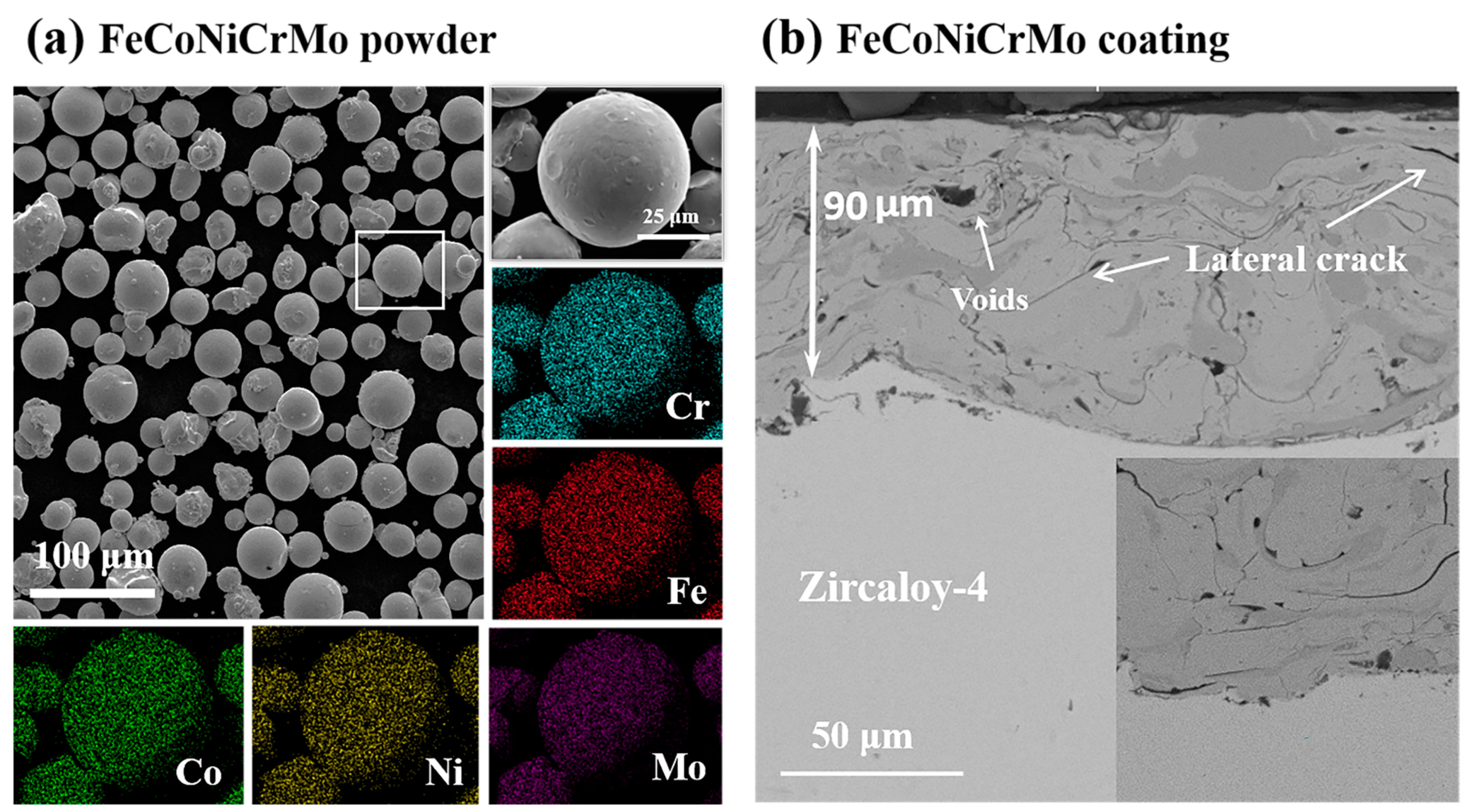
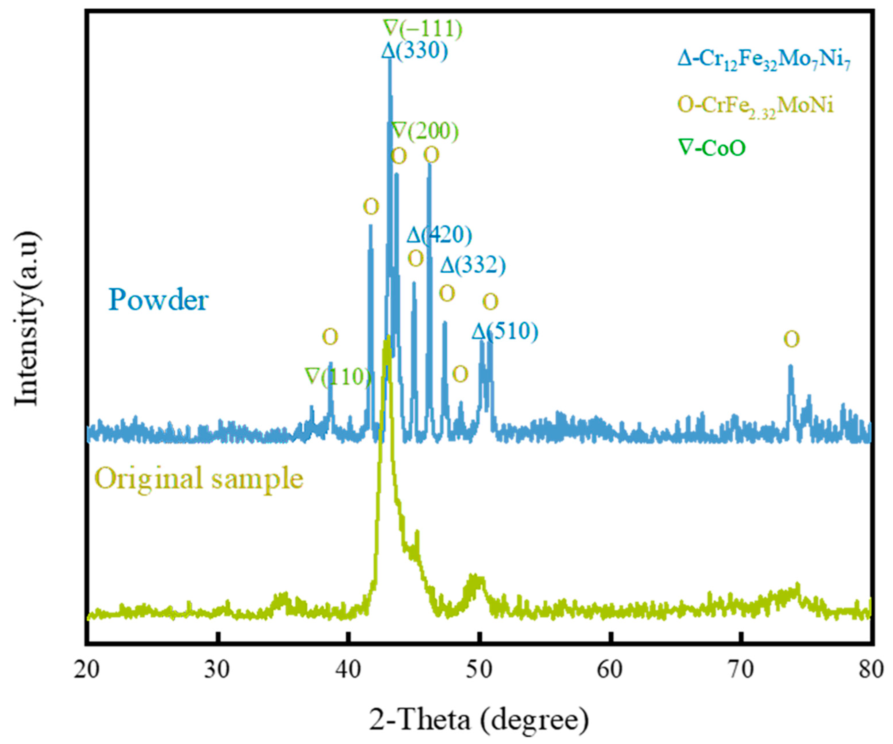
3.1. Microstructure of the Coatings

The surface morphologies and element distribution of the FeCoNiCrMo powders are shown in Figure 1a. The FeCoNiCrMo powder was mostly a circular shape. The particle size distributions of the powders were 25 to 45 μm. As shown in Figure 1b, the cross-sectional morphology and locally enlarged view of the FeCoNiCrMo coatings showed that the FeCoNiCrMo coatings had a typical layered structure sprayed by APS. The thickness of the coatings was 90 μm, and there was a clear boundary between the coatings and the substrates. The coatings and the substrates were tightly connected and had good connection performance. The FeCoNiCrMo coating was deposited on the surface of the zircaloy-4. Figure 2 shows the XRD patterns of the FeCoNiCrMo powders and the FeCoNiCrMo coatings surface. It could be seen that the diffraction peak of the FeCoNiCrMo coatings was relatively sharp, indicating that the coating has a crystalline structure. The coating was mainly composed of the Cr12Fe32Ni7Mo7 phase with (330) preferred orientation. Since the structures of all these elements are similar, the positions of the characteristic peaks are also similar. After becoming coated, the structure of these phases undergoes some changes, resulting in a slight shift in the position of the peaks, so that a broader diffraction peak appears. No diffraction peaks of the substrates are observed in the XRD diffraction peaks of the coatings, indicating that the thickness of the coatings exceeds the X-ray’s penetrating ability.
As shown in Figure 3, the main components of the sprayed coatings were FeCoNiCrMo. It shows that the FeCoNiCrMo coating was successfully prepared by APS. The microstructure of the coatings was caused by the deposition of the powder under the action of the plasma flame. The EDS elemental analysis corresponding to the SEM images of the cross-section of the FeCoNiCrMo coatings is shown in Figure 3. The coating’s thickness was about 90 μm. There were a few voids and cracks on the section of the FeCoNiCrMo coatings, but the voids and cracks were small. The zircaloy-4 substrates were uneven due to sandblasting. It can be observed that the oxygen content in the FeCoNiCrMo coating was lower than that in the zircaloy-4 substrates.

3.2. Oxidation Tests

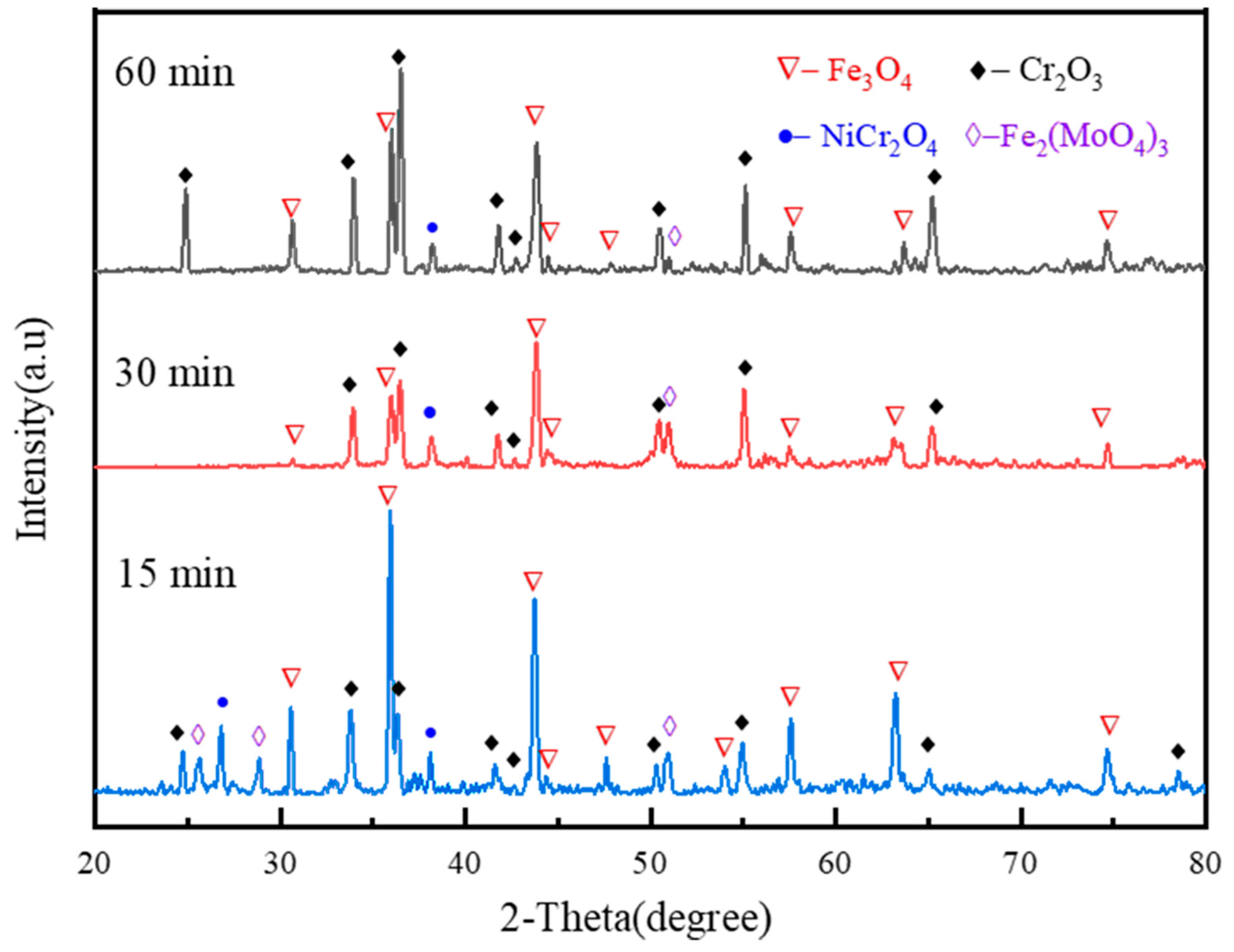
3.2.1. Surface XRD Analysis

Figure 4 shows the XRD patterns of the FeCoNiCrMo coatings oxidized for 15 min, 30 min, and 60 min. Their phase compositions are shown in Figure 4. The quantitative data based on XRD after oxidation at different times for the fractions of each phase are shown in Table 3. Due to the coatings being thick (about 90 μm), the X-rays were not penetrated the oxide layer, and only the oxides on the surface of the coatings could be detected. The XRD analysis shows that with the extension of oxidation time, the kinds of oxides changed little, but the peaks all changed. These oxides were Fe3O4 (PDF# 75-0449), NiCr2O4 (PDF# 23-1271), Fe2(MoO4)3 (PDF# 33-0661), and Cr2O3 (PDF# 88-1479), respectively, and the zircaloy-4 substrates had no obvious diffraction peak characteristics. After 15 min of oxidation, the peaks of Fe3O4 on the coating’s surface were obvious at the early stage of high-entropy coatings oxidation, and the peaks of spinels NiCr2O4 and lower Cr2O3 appeared. It was also observed that the intensity of Cr2O3 peaks increased with the extension of oxidation time compared with other oxides after oxidation for 30 min and 60 min. It was due to the increase in the thickness of the Cr2O3 layer. It reflected that the FeCoNiCrMo coatings had formed a Cr2O3 layer with good oxidation resistance, which improved the oxidation of the FeCoNiCrMo coatings and the zircaloy-4 substrates.

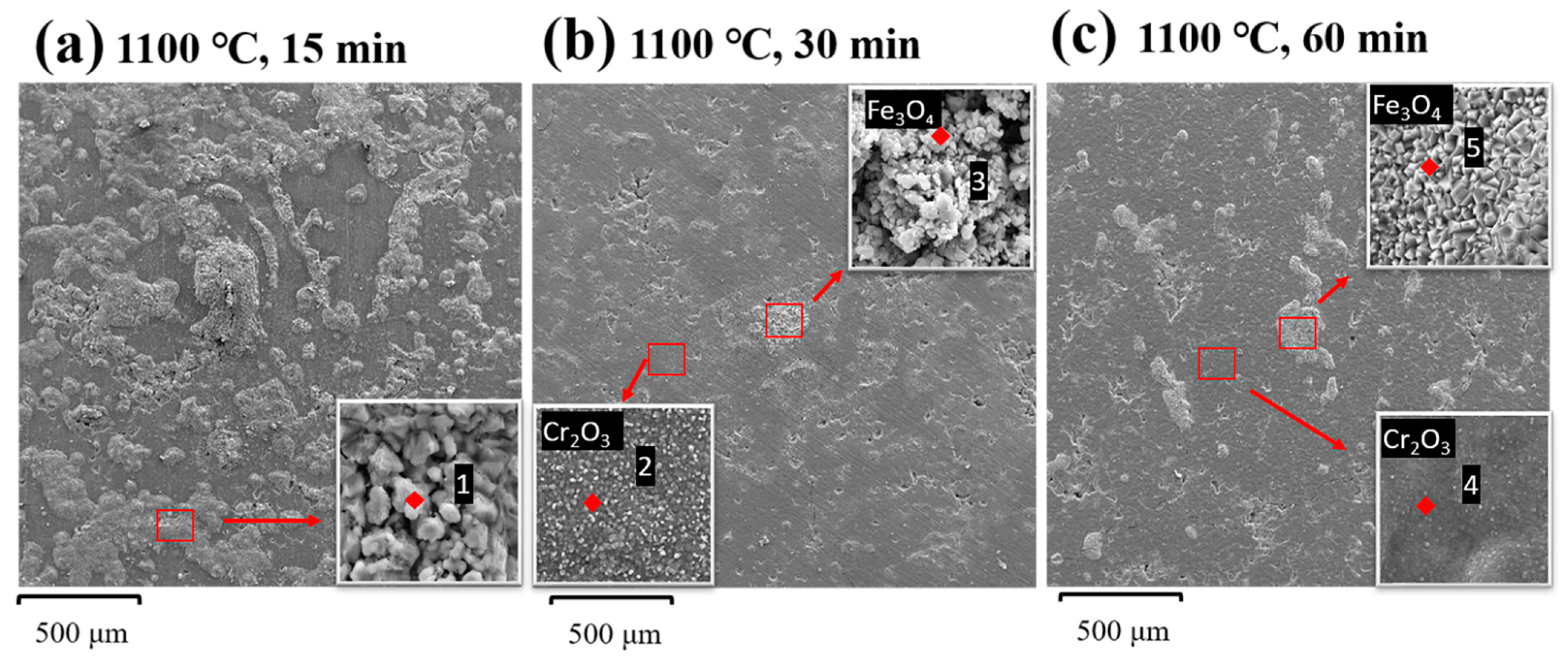
3.2.2. Surface Micromorphology and Oxidation Analysis

Figure 5 shows the surface morphologies of the FeCoNiCrMo coatings after oxidation at 1100 °C for 15 min, 30 min, and 60 min in a steam environment, and Table 4 shows the corresponding elemental compositions. In the initial stage of the oxidation process, the formation of the oxide layer depended on the chemical reaction. While in the further growth stages of the oxidation process, the formation of the oxide layer depended on the diffusion of elements to the substrate surface and the migration of ions to the oxide layer. Under different oxidation times, the oxidation results were significantly different, and the phase composition of the coating system changed, which affected the high-temperature oxidation resistance of the coatings. It can be observed by SEM that many phases with different morphologies were formed on the surface of the FeCoNiCrMo coatings because the elements with low activation energy were preferentially oxidized (selective oxidation) at the beginning of the oxidation reaction. After 15 min oxidation, a uniform Cr2O3 layer was formed on the surface of the FeCoNiCrMo coatings, and there were many convex oxides on the surface, such as NiCr2O4 and Fe3O4. The free energy of possible oxide formation at 1100 °C (ΔGf, kJ/mol) was, from small to large, Fe3O4 < NiCr2O4 < Cr2O3 < MoO3 < CoO < NiO [33].
The high-temperature oxidation of the FeCoNiCrMo coatings was controlled by the oxide binding energy and electronegativity of each element because it was related to the formation order of oxides. If the initially formed oxides have good high-temperature oxidation resistance, an oxide layer could be formed to prevent the steam from continuing to react with other elements, thereby improving the high-temperature oxidation resistance of the zircaloy-4 substrates. If the high-temperature oxidation resistance of the first-formed oxides is relatively poor, it can accelerate the reaction between steam and other elements of the coatings, thus worsening the high-temperature oxidation resistance of the FeCoNiCrMo coatings. Therefore, Fe3O4 and NiCr2O4 spinels were first formed in the high-temperature oxidation process of the FeCoNiCrMo coatings at 1100 °C, and it can be seen from SEM that the structures of the Fe3O4 and NiCr2O4 spinels were relatively loose, and the high-temperature oxidation resistance was relatively poor, so steam reacted with Cr to form Cr2O3, and then formed a Cr2O3 layer. It is consistent with the products detected by XRD.
After oxidation for 15 min and 30 min, it was observed that the surface oxide layer of the coatings was divided into two layers, the outer layer was a loose and porous agglomerated oxide composed of Fe3O4 and NiCr2O4 spinels, and the inner layer was a dense and protective oxide layer composed of Cr2O3. The outer layer had poor high-temperature oxidation resistance and the inner layer had better high-temperature oxidation resistance, which promoted the uniform growth of the Cr2O3 layer and reduced the mutual diffusion of oxygen and other elements. Liu et al. [34] found that the presence of Cr helped to form a Cr-Fe mixed oxide film, thus further inhibiting the formation of a strong Fe oxide layer on the surface of the HEAs, thereby reducing the oxidation rate. Therefore, after the protective and dense Cr2O3 layer was formed on the surface of the FeCoNiCrMo coatings during the oxidation process, the element’s diffusion was hindered, thus reducing the oxidation process. Therefore, it also prevented the outward diffusion of Fe, Co, and Ni elements. After oxidation for 30 min and 60 min, it could be found that with the extension of oxidation time, Cr2O3 in the coatings gradually increased, the Cr2O3 layer gradually thickened, and the oxide agglomerated on the surface gradually decreased, forming a dense and continuous oxide layer with good high-temperature oxidation resistance. The thumbnail in Figure 5 shows the surface morphology and elemental composition of the aggregated oxides and Cr2O3. The aggregated oxides were composed of closely spaced blocks, and the Cr2O3 was uniformly covered in the form of scales. Therefore, the protective and dense oxide layer formed on the surface of the FeCoNiCrMo coatings had good high-temperature oxidation resistance.

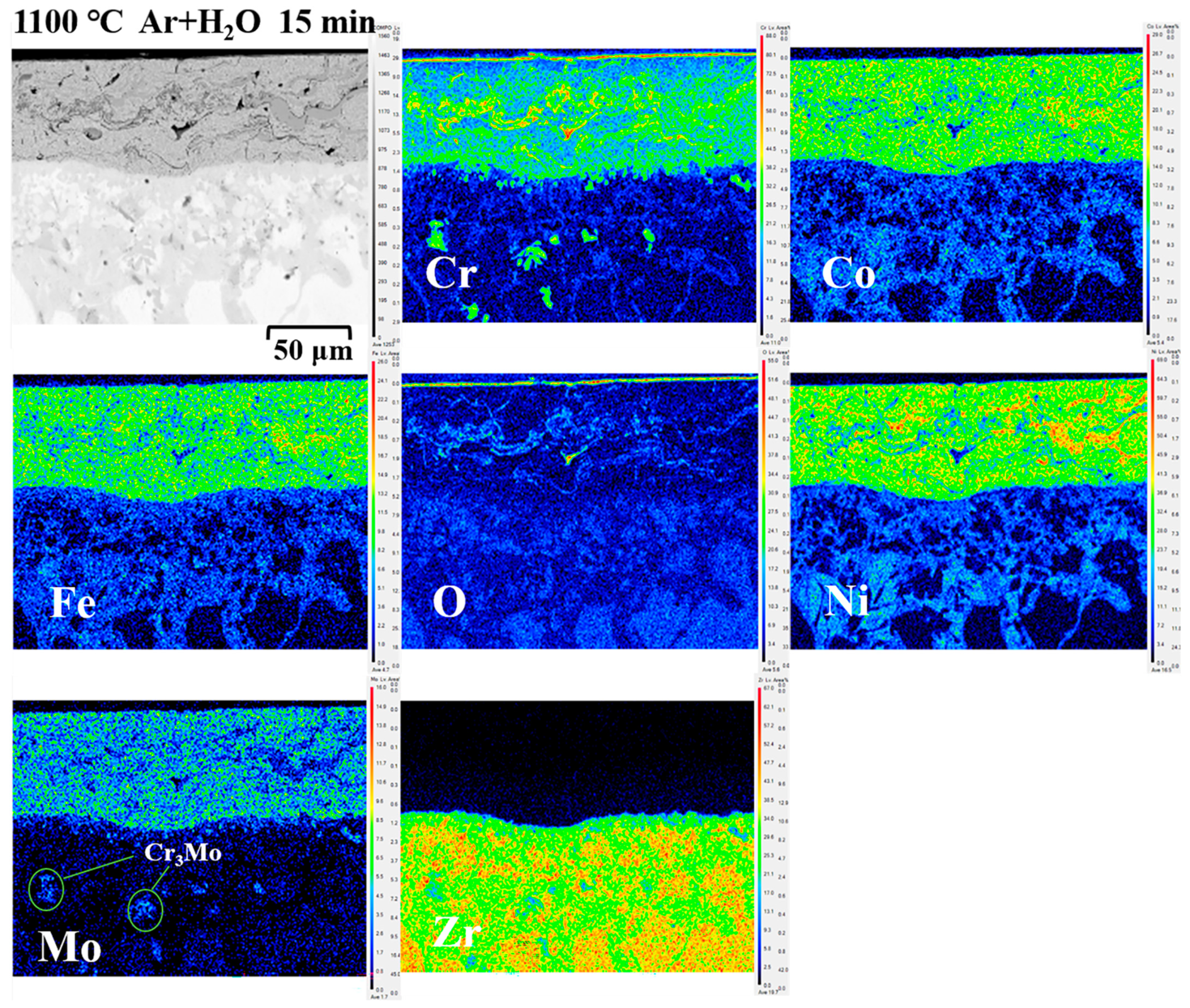
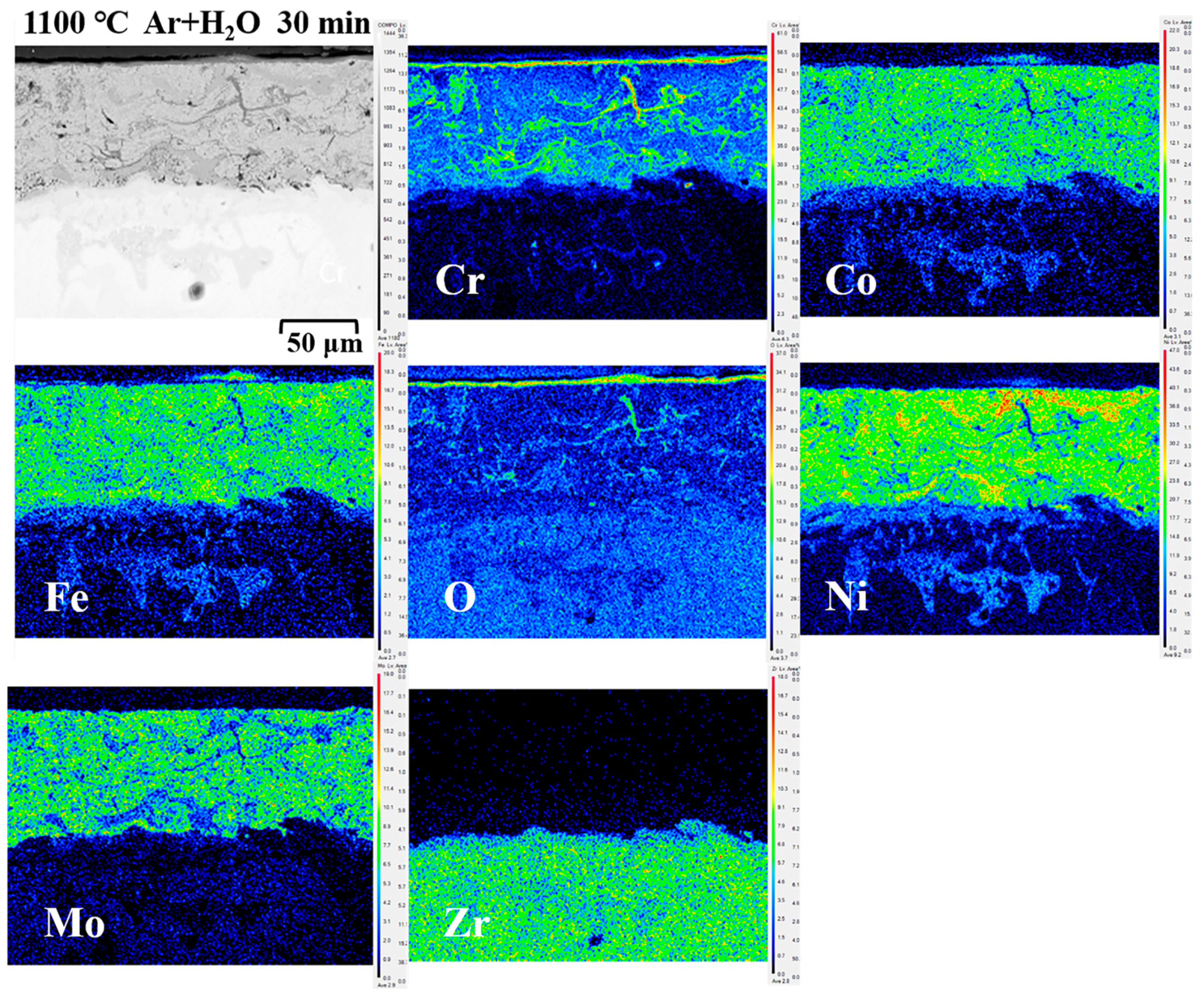
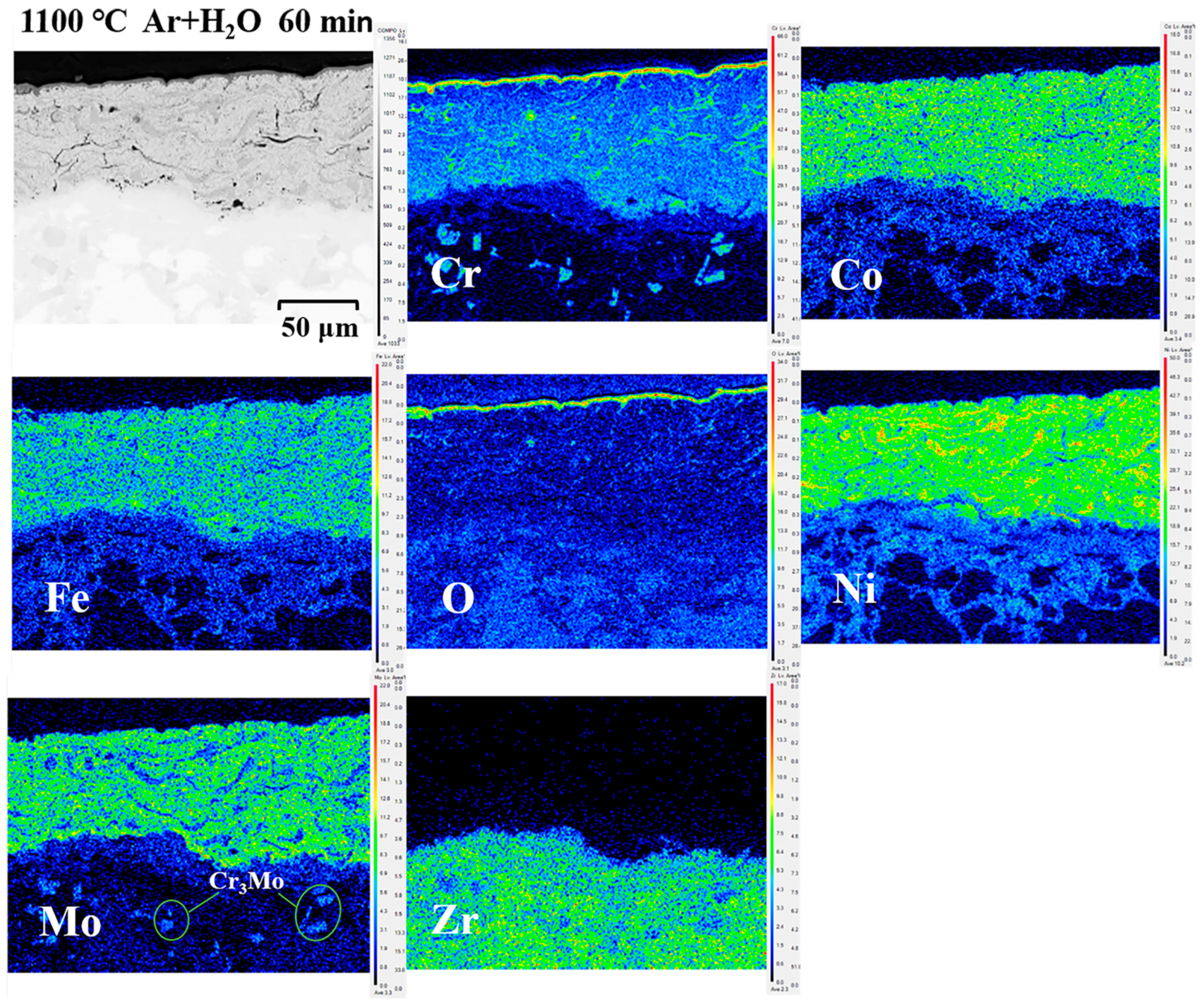
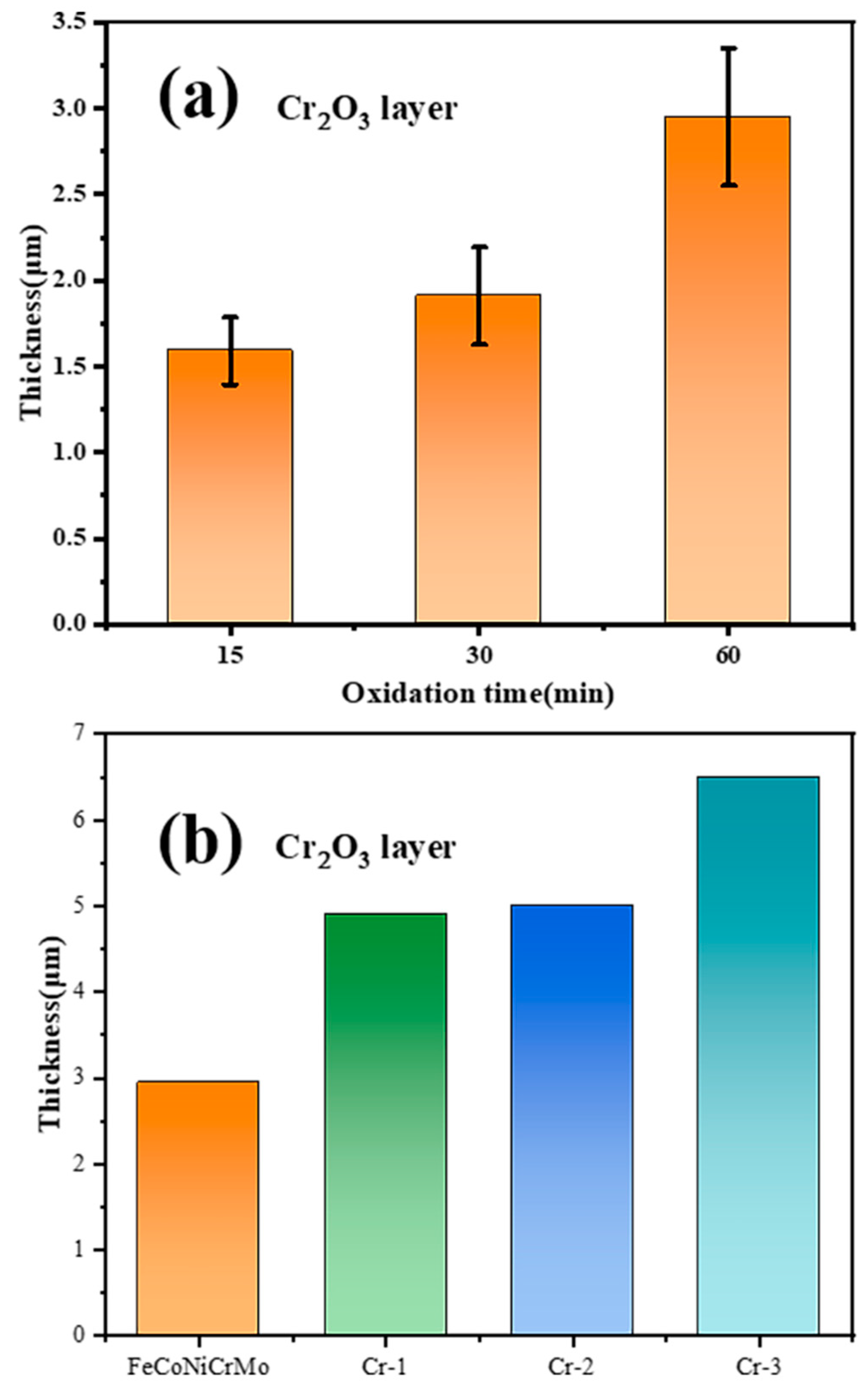
3.2.3. Cross-Sectional Micromorphology and Oxidation Analysis

It is seen from Figure 6 and Figure 9 that the cross-sectional morphology of the specimens after 15 min of oxidization was mainly divided into some layers: the Cr2O3 oxide layer generated on the surface, the FeCoNiCrMo coatings, and the zircaloy-4 substrates. It is seen from Figure 6 that there were no clear vertical cracks in the morphologies of the coatings, only some cracks and pores, but the cracks did not extend to the interface. There were voids and cracks in the FeCoNiCrMo layer. It was due to the existence of the Mo element. Mo formed MoO3 with oxygen elements, and MoO3 was easily volatilized at high temperatures. The volatilized MoO3 formed pores in the FeCoNiCrMo coatings, and Mo-O had high stress. After volatilization, it led to large stress and cracks in the oxide layer, which promoted the formation of cracks. It was found that the presence of the Mo element was not conducive to the oxidation resistance and high-temperature stability of the FeCoNiCrMo coatings. However, due to the formation of a dense and protective Cr2O3 layer on the FeCoNiCrMo coatings during the oxidation process, the diffusion of elements was hindered, so the cracks caused by the volatilization of MoO3 were also reduced. It is seen that compared with Figure 3 and Figure 6, the oxygen content in the FeCoNiCrMo coatings was still slightly lower than that in the zircaloy-4 substrates. It indicated that oxygen penetrated the FeCoNiCrMo coatings, but because of its low solubility in the coatings, its contents in the coatings were low. Compared with the original specimen, most of the oxygen elements in the FeCoNiCrMo coatings after oxidation were concentrated in the surface oxide layer. The thin but dense Cr2O3 layer shows that the FeCoNiCrMo coatings provided effective protection.
Figure 7 and Figure 9 show the cross-sectional morphologies and corresponding elemental compositions of the FeCoNiCrMo coatings after 30 min of oxidization at 1100 °C. A complete and clear Cr2O3 layer was formed on the FeCoNiCrMo coatings, and the oxide layer was continuous and dense. Due to the thickening of the Cr2O3 layer, Mo was prevented from diffusing outward to form oxides with oxygen elements, and the pores or cracks caused by the evaporation of MoO3 during high-temperature oxidation were reduced. Cr promoted the formation of the protective dense oxide layer, hindered the outward diffusion of elements, and improved the oxidation resistance [35].
Figure 8 and Figure 9 show the cross-sectional morphologies and corresponding elemental compositions of the FeCoNiCrMo coatings after 60 min of oxidation at 1100 °C. Some laminar cracks and short vertical cracks appeared in the FeCoNiCrMo coatings, but the cracks did not expand to the interface. The cracks in the FeCoNiCrMo coatings were the result of the speedy cooling of the specimens in air. Under nuclear reactor conditions, cracks and spalling of the coatings were not allowed because the phenomena led to the loss of oxidation resistance of the coatings. However, it is found from Figure 9 that the thickness of the oxide layer gradually thickened with the increases of time, and the increase after 60 min was larger than that after 15 min or 30 min. The oxide layer was closely connected with the coatings and there were no bubbles, holes, or other defects at the connection, and no fall-off with the coatings. Therefore, although there were defects related to cracks and voids, the coatings were not delaminated, and the FeCoNiCrMo coating was complete. The generated Cr2O3 layer was uniformly and closely coated, showing good high-temperature oxidation resistance. It can be seen from Figure 10b that compared with pure Cr coatings [36,37,38], the thickness of the Cr2O3 layer of the FeCoNiCrMo coatings is thinner than that of pure Cr coatings at the same time and in the same environment. The thinner the dense oxide layer generated on the surface at the same time of oxidation, the longer the protection time will be. Therefore, it was considered that the cracks on the FeCoNiCrMo coatings existed but had little effect at high temperatures. In all oxidation tests, the FeCoNiCrMo coatings formed a dense Cr2O3 layer on the surface, which effectively protected the zircaloy-4 substrates.

3.3. Diffusion of Coatings/Zircaloy

To understand the diffusion behavior of the FeCoNiCrMo coatings/zircaloy-4 under high-temperature steam, it can be seen from the EPMA in Figure 6, Figure 7 and Figure 8 that Cr-rich flocculent precipitate phase appeared in the zircaloy-4 substrates. The distribution of the Cr-rich flocculent precipitate phase was consistent with the distribution of Mo in the zircaloy-4 substrates, and the distribution concentration ratio of the Cr and Mo elements was about 3:1, that is to say, the zircaloy-4 substrates and the coatings appeared as a diffusion phenomenon, and part of the Cr diffused into the zircaloy-4 substrates and formed flocculent Cr-rich precipitate phase in the zircaloy-4 substrates. According to previous literature, Mo and Cr form MoCr3 at high temperatures [35]. This is consistent with the Cr-Mo phase diagram; therefore, it is speculated that the flocculent Cr-rich precipitate phase is MoCr3 in Figure 6. The reaction is expressed as:
Mo + 3Cr = Cr3Mo
During high-temperature oxidation due to the mutual diffusion of Cr-Mo, MoCr3 grew and formed a flocculent precipitate phase.
The cross-sectional morphologies and EDS of the coatings after oxidation at 1100 °C show that the FeCoNiCrMo coatings had high-temperature oxidation resistance and good adhesion. Zhang et al. [39] found that Cr enhanced the increase of the BCC phase, and the existence of multiple BCC/FCC phase boundaries promoted the diffusion of active elements (Fe, Co, Ni). Diffusion also occurred at the interface of the coatings and the zircaloy-4, as observed in Figure 6, Figure 7 and Figure 8, because the order of diffusivity of elements was DCr > DFe > DCo > DNi [39,40,41,42]. Cr formed Cr2O3 with oxygen ions first, while Fe, Co, and Ni elements diffused into the zircalloy-4 substrates. Because the electronegativity of Fe, Co, and Ni elements were similar, and the electronegativity difference with that of the zircaloy-4 was very small, the smaller the electronegativity difference, the easier it was to diffuse, and vice versa. Therefore, Fe, Co, and Ni elements were easy to diffuse into the zircaloy-4. The electronegativity of Mo was quite different from that of the zircaloy-4, and Mo was easy to form the MoCr3 precipitate phase with Cr, which was less diffused than the other four elements. It was consistent with the law of diffusion influencing factors. The mutual diffusion between Mo and Zr was also very limited. For example, Sweeney Jr. et al. [43] found that a mutual diffusion layer with a thickness of only 5 mm between the coating and the zircaloy-4 substrate was reported in a diffusion coupling experiment at 1100 °C. A diffusion barrier layer was covered to reduce or prevent the element diffusion and improved the applicability of the FeCoNiCrMo coatings.
Since the high-entropy coating is applied to cladding with zircaloy-4, the coating needs to have not only good resistance to oxidation but also to irradiation. The mixture of elements in the high-entropy coatings leads to the possibility of obtaining high irradiation resistance through their unique “self-repair” mechanism. Zhang et al. [44] reviewed the irradiation behavior of high phase stability high-entropy alloys under fast electron or accelerated MeV heavy ion irradiation and found that the irradiation-induced volume expansion of AlxCoCrFeNi high-entropy alloys was lower than that of conventional nuclear materials under similar irradiation conditions. Xia et al. [45] investigated two Mo0.5NbTiVCr0.25 and Mo0.5NbTiV0.5Zr0.25 high-entropy alloys subjected to helium ion irradiation simulated neutron irradiation to study the irradiation-induced evolution of crystal structure, hardness, and microstructure. It was found that the irradiated hardness of Zr-HEA and Cr-HEA increased by 19.18% and 19.23%, respectively, compared to the original hardness under high irradiation, and that the irradiation hardening was lower in both cases compared to most conventional alloys. Sadeghilaridjani et al. [46] studied the irradiation behavior of high-temperature and high-entropy alloy HfTaTiVZr. Additionally, the irradiation-induced structural changes and amorphization were found to be relatively limited. The slow diffusion of atoms in the high-entropy coating reduces the gap mobility and vacancy mobility, limiting the damage caused by irradiation. Therefore, the high-entropy coating has good resistance to irradiation even under irradiation conditions [44].

4. Conclusions

The FeCoNiCrMo coating was successfully prepared on the zircaloy-4 substrates by APS technology to enhance the high-temperature oxidation resistance of the substrates. The oxidation behavior of the FeCoNiCrMo coatings on the zircaloy-4 in steam at 1100 °C was systematically studied. The composition and microstructure of the FeCoNiCrMo coatings on the zircaloy-4 after high-temperature oxidation in steam were studied. Some main conclusions can be reached from this:
After the initial oxidation of FeCoNiCrMo coatings, porous Fe3O4 and NiCr2O4 oxides were first formed on the coatings surface, but a dense Cr2O3 layer was formed with further oxidation.
The FeCoNiCrMo coatings reacted with oxygen ions at high temperatures to form the Cr2O3 layer, which grew from 1.5 to 3 μm after 15 to 60 min of oxidation. The Cr2O3 layer can effectively slow down the oxidation of the zircaloy-4 as an oxygen diffusion barrier.
The dense Cr2O3 layer prevented the diffusion of Mo and the formation of MoO3 and reduced the formation of pores and cracks caused by higher stress after the volatilization of MoO3 in the coatings. However, Cr-Mo diffused together to the substrate and formed Cr3Mo precipitates in zircaloy-4.

Author Contributions

Conceptualization, L.W.; methodology, L.W.; software, L.W. and J.W.; validation, B.Y.; formal analysis, B.Y. and Z.Y.; investigation, L.W.; resources, L.W.; data curation, L.W., Q.L. and Z.Y.; writing—original draft preparation, L.W.; writing—review and editing, L.W., Q.L. and P.S.; visualization, B.Y.; supervision, Q.L. and P.S.; project administration, Q.L.; funding acquisition, P.S. All authors have read and agreed to the published version of the manuscript.

Funding

National Natural Science Foundation of China (No. 52071168) and the Rare and Precious Metal Materials Genome Engineering Project of Yunnan Province (No. 202002AB080001).

Institutional Review Board Statement

Not applicable.

Informed Consent Statement

Not applicable.

Data Availability Statement

Not applicable.

Acknowledgments

Thanks to Nuclear Power Institute of China for providing zircaloy-4 substrate.

Conflicts of Interest

The authors declare no conflict of interest.

References

  1. Ma, X.-F.; Wu, Y.-W.; Tan, J.; Meng, C.-Y.; Yang, L.; Dang, W.-A.; He, X.-J. Evaluation of corrosion and oxidation behaviors of TiAlCrN coatings for nuclear fuel cladding. Surf. Coat. Technol. 2019, 358, 521–530. [Google Scholar] [CrossRef]
  2. Alat, E.; Motta, A.T.; Comstock, R.J.; Partezana, J.M.; Wolfe, D.E. Ceramic coating for corrosion (c3) resistance of nuclear fuel cladding. Surf. Coat. Technol. 2015, 281, 133–143. [Google Scholar] [CrossRef] [Green Version]
  3. Kim, H.G.; Kim, I.H.; Jung, Y.I.; Park, D.J.; Koo, Y.H. Development of Surface Modified Zr Cladding by Coating Technology for ATF. In Proceedings of the Top Fuel, Boise, ID, USA, 11–15 September 2016. [Google Scholar]
  4. Kim, H.G.; Kim, I.H.; Jung, Y.I.; Park, D.J.; Koo, Y.H. Progress of surface modified Zr cladding development for ATF in Korea. In Proceedings of the 2017 Water Reactor Fuel Performance Meeting, Ramada Plaza Jeju, Jeju Island, Korea, 10–14 September 2017. [Google Scholar]
  5. Wei, T.; Zhang, R.; Yang, H.; Liu, H.; Qiu, S.; Wang, Y.; Du, P.; He, K.; Hu, X.; Dong, C. Microstructure, corrosion resistance and oxidation behavior of Cr-coatings on Zircaloy-4 prepared by vacuum arc plasma deposition. Corros. Sci. 2019, 158, 108077. [Google Scholar] [CrossRef]
  6. Chen, Q.S.; Liu, C.H.; Zhang, R.Q.; Yang, H.Y.; Wei, T.G.; Wang, Y.; Li, Z.; He, L.X.; Wang, J.; Wang, L.; et al. Microstructure and high-temperature steam oxidation properties of thick Cr coatings prepared by magnetron sputtering for accident tolerant fuel claddings: The role of bias in the deposition process. Corros. Sci. 2020, 165, 108378. [Google Scholar] [CrossRef]
  7. Park, J.-H.; Kim, H.-G.; Park, J.-y.; Jung, Y.-I.; Park, D.-J.; Koo, Y.-H. High temperature steam-oxidation behavior of arc ion plated Cr coatings for accident tolerant fuel claddings. Surf. Coat. Technol. 2015, 280, 256–259. [Google Scholar] [CrossRef]
  8. Li, Q.; Wang, Y.; Du, P.; Song, P.; Zhang, R.; Li, Z.; Lu, J. Oxidation properties and microstructure of a chromium coating on zircaloy-4 fuel cladding material applied by atmospheric plasma spraying. J. Nucl. Mater. 2022, 560, 153496. [Google Scholar] [CrossRef]
  9. Li, Q.; Song, P.; Zhang, R.; Li, Z.; Wang, Y.; Du, P.; Lu, J. Oxidation behavior and Cr-Zr diffusion of Cr coatings prepared by atmospheric plasma spraying on zircaloy-4 cladding in steam at 1300 °C. Corros. Sci. 2022, 203, 110378. [Google Scholar] [CrossRef]
  10. Cheng, B.; Kim, Y.-J.; Chou, P. Improving Accident Tolerance of Nuclear Fuel with Coated Mo-alloy Cladding. Nucl. Eng. Technol. 2016, 48, 16–25. [Google Scholar] [CrossRef] [Green Version]
  11. Dabney, T.; Johnson, G.; Yeom, H.; Maier, B.; Walters, J.; Sridharan, K. Experimental evaluation of cold spray FeCrAl alloys coated zirconium-alloy for potential accident tolerant fuel cladding. Nucl. Mater. Energy 2019, 21, 100715. [Google Scholar] [CrossRef]
  12. Gigax, J.G.; Kennas, M.; Kim, H.; Wang, T.; Maier, B.R.; Yeom, H.; Johnson, G.O.; Sridharan, K.; Shao, L. Radiation response of Ti2AlC MAX phase coated Zircaloy-4 for accident tolerant fuel cladding. J. Nucl. Mater. 2019, 523, 26–32. [Google Scholar] [CrossRef]
  13. Maier, B.R.; Garcia-Diaz, B.L.; Hauch, B.; Olson, L.C.; Sindelar, R.L.; Sridharan, K. Cold spray deposition of Ti2AlC coatings for improved nuclear fuel cladding. J. Nucl. Mater. 2015, 466, 712–717. [Google Scholar] [CrossRef]
  14. Kuprin, A.S.; Belous, V.A.; Voyevodin, V.N.; Bryk, V.V.; Vasilenko, R.L.; Ovcharenko, V.D.; Reshetnyak, E.N.; Tolmachova, G.N.; V’Yugov, P.N. Vacuum-arc chromium-based coatings for protection of zirconium alloys from the high-temperature oxidation in air. J. Nucl. Mater. 2015, 465, 400–406. [Google Scholar] [CrossRef]
  15. Zou, Y.; Wheeler, J.M.; Ma, H.; Okle, P.; Spolenak, R. Nanocrystalline High-Entropy Alloys: A New Paradigm in High-Temperature Strength and Stability. Nano Lett. 2017, 17, 1569–1574. [Google Scholar] [CrossRef]
  16. Munitz, A.; Meshi, L.; Kaufman, M.J. Heat treatments’ effects on the microstructure and mechanical properties of an equiatomic Al-Cr-Fe-Mn-Ni high entropy alloy. Mater. Sci. Eng. A 2017, 689, 384–394. [Google Scholar] [CrossRef] [Green Version]
  17. Yeh, J.W.; Chen, S.K.; Lin, S.J.; Gan, J.Y.; Chin, T.S.; Shun, T.T.; Tsau, C.H.; Chang, S.Y. Nanostructured High-Entropy Alloys with Multiple Principal Elements: Novel Alloy Design Concepts and Outcomes. Adv. Eng. Mater. 2004, 6, 299–303. [Google Scholar] [CrossRef]
  18. Hsu, W.L.; Murakami, H.; Yeh, J.W.; Yeh, A.C.; Shimoda, K. A Heat-Resistant NiCo0.6Fe0.2Cr1.5SiAlTi0.2 Overlay Coating for High-Temperature Applications. J. Electrochem. Soc. 2016, 163, C752–C758. [Google Scholar] [CrossRef]
  19. Fang, Q.; Chen, Y.; Li, J.; Liu, Y.; Liu, Y. Microstructure and mechanical properties of FeCoCrNiNbX high-entropy alloy coatings. Phys. B Condens. Matter 2018, 550, 112–116. [Google Scholar] [CrossRef]
  20. Chen, Q.; Liu, C.; Long, J.; Wang, J.; Zhang, R.; Yang, H.; Zhang, W.; Yao, F.; Zhao, S.; Zhang, Q. Microstructure and corrosion characteristics of CrCuFeMoNi HEA coatings with different compositions in high-temperature and high-pressure water. Mater. Res. Express 2019, 6, 086511. [Google Scholar] [CrossRef]
  21. Huang, Y.-S.; Chen, L.; Lui, H.-W.; Cai, M.-H.; Yeh, J.-W. Microstructure, hardness, resistivity and thermal stability of sputtered oxide films of AlCoCrCu0.5NiFe high-entropy alloy. Mater. Sci. Eng. A 2007, 457, 77–83. [Google Scholar] [CrossRef]
  22. Tian, Y.; Lu, C.; Shen, Y.; Feng, X. Microstructure and corrosion property of CrMnFeCoNi high entropy alloy coating on Q235 substrate via mechanical alloying method. Surf. Interfaces 2019, 15, 135–140. [Google Scholar] [CrossRef]
  23. Qiu, X.-W.; Zhang, Y.-P.; He, L.; Liu, C.-G. Microstructure and corrosion resistance of AlCrFeCuCo high entropy alloy. J. Alloys Compd. 2013, 549, 195–199. [Google Scholar] [CrossRef]
  24. Huang, C.; Zhang, Y.; Shen, J.; Vilar, R. Thermal stability and oxidation resistance of laser clad TiVCrAlSi high entropy alloy coatings on Ti–6Al–4V alloy. Surf. Coat. Technol. 2011, 206, 1389–1395. [Google Scholar] [CrossRef]
  25. Hsu, W.-L.; Murakami, H.; Araki, H.; Watanabe, M.; Kuroda, S.; Yeh, A.-C.; Yeh, J.-W. A Study of NiCo0.6Fe0.2CrxSiAlTiyHigh-Entropy Alloys for Applications as a High-Temperature Protective Coating and a Bond Coat in Thermal Barrier Coating Systems. J. Electrochem. Soc. 2018, 165, C524–C531. [Google Scholar] [CrossRef]
  26. Mohanty, A.; Sampreeth, J.K.; Bembalge, O.; Hascoet, J.Y.; Marya, S.; Immanuel, R.J.; Panigrahi, S.K. High temperature oxidation study of direct laser deposited AlXCoCrFeNi (X = 0.3,0.7) high entropy alloys. Surf. Coat. Technol. 2019, 380, 125028. [Google Scholar] [CrossRef]
  27. Xu, Q.-L.; Zhang, Y.; Liu, S.-H.; Li, C.-J.; Li, C.-X. High-temperature oxidation behavior of CuAlNiCrFe high-entropy alloy bond coats deposited using high-speed laser cladding process. Surf. Coat. Technol. 2020, 398, 126093. [Google Scholar] [CrossRef]
  28. Daoud, H.M.; Manzoni, A.M.; Völkl, R.; Wanderka, N.; Glatzel, U. Oxidation Behavior of Al8Co17Cr17Cu8Fe17Ni33, Al23Co15Cr23Cu8Fe15Ni15, and Al17Co17Cr17Cu17Fe17Ni17 Compositionally Complex Alloys (High-Entropy Alloys) at Elevated Temperatures in Air. Adv. Eng. Mater. 2015, 17, 1134–1141. [Google Scholar] [CrossRef]
  29. Laplanche, G.; Volkert, U.; Eggeler, G.; George, E. Oxidation behavior of the CrMnFeCoNi high-entropy alloy. Oxid. Met. 2016, 85, 629–645. [Google Scholar] [CrossRef]
  30. Butler, T.M.; Chaput, K.J.; Dietrich, J.R.; Senkov, O.N. High temperature oxidation behaviors of equimolar NbTiZrV and NbTiZrCr refractory complex concentrated alloys (RCCAs). J. Alloys Compd. 2017, 729, 1004–1019. [Google Scholar] [CrossRef]
  31. Gorr, B.; Mueller, F.; Christ, H.J.; Mueller, T.; Chen, H.; Kauffmann, A.; Heilmaier, M. High temperature oxidation behavior of an equimolar refractory metal-based alloy 20Nb20Mo20Cr20Ti20Al with and without Si addition. J. Alloys Compd. 2016, 688, 468–477. [Google Scholar] [CrossRef] [Green Version]
  32. Zhang, P.; Li, Y.; Chen, Z.; Zhang, J.; Shen, B. Oxidation response of a vacuum arc melted NbZrTiCrAl refractory high entropy alloy at 800–1200 °C. Vacuum 2019, 162, 20–27. [Google Scholar] [CrossRef]
  33. Barin, I.; Platzki, G. Thermochemical Data of Pure Substances; Wiley Online Library: Hoboken, NJ, USA, 1989; Volume 304. [Google Scholar]
  34. Liu, Y.-x.; Cheng, C.-q.; Shang, J.-l.; Wang, R.; Li, P.; Zhao, J. Oxidation behavior of high-entropy alloys AlxCoCrFeNi (x = 0.15, 0.4) in supercritical water and comparison with HR3C steel. Trans. Nonferrous Met. Soc. China 2015, 25, 1341–1351. [Google Scholar] [CrossRef]
  35. Syrtanov, M.S.; Kashkarov, E.B.; Abdulmenova, A.V.; Sidelev, D.V. High-temperature oxidation of Zr1Nb zirconium alloy with protective Cr/Mo coating. Surf. Coat. Technol. 2022, 439, 128459. [Google Scholar] [CrossRef]
  36. Han, X.; Xue, J.; Peng, S.; Zhang, H. An interesting oxidation phenomenon of Cr coatings on Zry-4 substrates in high temperature steam environment. Corros. Sci. 2019, 156, 117–124. [Google Scholar] [CrossRef]
  37. Ma, H.-B.; Zhao, Y.-H.; Liu, Y.; Zhu, J.-T.; Yan, J.; Liu, T.; Ren, Q.-S.; Liao, Y.-H.; Liu, G.; Lin, X.-D.; et al. Self-healing behavior of Cr-coated Zr alloy cladding in high temperature steam oxidation process. J. Nucl. Mater. 2022, 558, 153327. [Google Scholar] [CrossRef]
  38. Hu, X.; Dong, C.; Wang, Q.; Chen, B.; Yang, H.; Wei, T.; Zhang, R.; Gu, W.; Chen, D. High-temperature oxidation of thick Cr coating prepared by arc deposition for accident tolerant fuel claddings. J. Nucl. Mater. 2019, 519, 145–156. [Google Scholar] [CrossRef]
  39. Zhang, Y.; Wu, H.; Yu, X.; Tang, D. Role of Cr in the high-temperature oxidation behavior of CrxMnFeNi high-entropy alloys at 800 °C in air. Corros. Sci. 2022, 200, 110211. [Google Scholar] [CrossRef]
  40. Tsai, K.Y.; Tsai, M.H.; Yeh, J.W. Sluggish diffusion in Co–Cr–Fe–Mn–Ni high-entropy alloys. Acta Mater. 2013, 61, 4887–4897. [Google Scholar] [CrossRef]
  41. Kai, W.; Li, C.C.; Cheng, F.P.; Chu, K.P.; Huang, R.T.; Tsay, L.W.; Kai, J.J. Air-oxidation of FeCoNiCr-based quinary high-entropy alloys at 700–900 °C. Corros. Sci. 2017, 121, 116–125. [Google Scholar] [CrossRef]
  42. Huang, P.K.; Yeh, J.W.; Shun, T.T.; Chen, S.K. Multi-principal-element alloys with improved oxidation and wear resistance for thermal spray coating. Adv. Eng. Mater. 2004, 6, 74–78. [Google Scholar] [CrossRef]
  43. Sweeney, W.E.; Batt, A.P. Electron probe and X-ray diffraction measurements of intermediate phases in Zr diffused with Cr, Fe, Ni, Cu and Mo. J. Nucl. Mater. 1964, 13, 87–91. [Google Scholar] [CrossRef]
  44. Zhang, Z.; Han, E.H.; Xiang, C. Irradiation behaviors of two novel single-phase bcc-structure high-entropy alloys for accident-tolerant fuel cladding. J. Mater. Sci. Technol. 2021, 84, 230–238. [Google Scholar] [CrossRef]
  45. Xia, S.Q.; Zhen, W.A.N.G.; Yang, T.F.; Zhang, Y. Irradiation Behavior in High Entropy Alloys. J. Iron Steel Res. 2015, 22, 879–884. [Google Scholar] [CrossRef]
  46. Sadeghilaridjani, M.; Ayyagari, A.; Muskeri, S.; Hasannaeimi, V.; Salloom, R.; Chen, W.-Y.; Mukherjee, S. Ion irradiation response and mechanical behavior of reduced activity high entropy alloy. J. Nucl. Mater. 2020, 529, 151955. [Google Scholar] [CrossRef]
Figure 1. (a) SEM surface morphology of the FeCoNiCrMo powder; (b) cross-section morphology of the FeCoNiCrMo coatings on the zircaloy-4 substrates.
Crystals 12 01529 g001
Figure 2. Surface XRD patterns for the FeCoNiCrMo powder and the FeCoNiCrMo coatings.
Crystals 12 01529 g002
Figure 3. EPMA elemental mapping of the FeCoNiCrMo coatings on the zircaloy-4 substrates.
Crystals 12 01529 g003
Figure 4. Surface XRD patterns for the FeCoNiCrMo coatings after oxidation at 1100 °C for 15 min, 30 min, and 60 min in a steam environment.
Crystals 12 01529 g004
Figure 5. Surface morphologies of the FeCoNiCrMo coatings after oxidation at 1100 °C for 15 min (a), 30 min (b), and 60 min (c) in a steam environment.
Crystals 12 01529 g005
Figure 6. EPMA elemental mapping of the FeCoNiCrMo coatings after 15 min of oxidation at 1100 °C in a steam environment.
Crystals 12 01529 g006
Figure 7. EPMA elemental mapping of the FeCoNiCrMo coatings after 30 min of oxidation at 1100 °C in a steam environment.
Crystals 12 01529 g007
Figure 8. EPMA elemental mapping of the FeCoNiCrMo coatings after 60 min of oxidation at 1100 °C in a steam environment.
Crystals 12 01529 g008
Figure 9. Cross-sectional SEM images of the FeCoNiCrMo coatings after oxidation at 1100 °C for 15 min (a), 30 min (b), and 60 min (c) in a steam environment and the line scans (d) of the oxide layer for 15 min.
Crystals 12 01529 g009
Figure 10. (a) The thickness of the Cr2O3 layer on the FeCoNiCrMo coatings after oxidation at 1100 °C for 15 min, 30 min, and 60 min in a steam environment, and (b) the thickness of the Cr2O3 layer on the pure Cr coatings after oxidation for 60 min: Cr-1 [36], Cr-2 [37], and Cr-3 [38].
Crystals 12 01529 g010
Table 1. Chemical composition (in wt.%) of the zircaloy-4 substrates.
ZrSnFeCrNiSiO
Zr-4 alloy composition Base1.2–1.70.18–0.240.07–0.13--1400 ppm
Measuring composition Base1.450.230.120.030.90.13
Table 2. Spraying parameters of the plasma spraying system.
Parameter Magnitude
Spraying voltage 50 V
Spraying current 610 A
Powder feed voltage 3.5 V
Standoff distance 100 mm
Moving rate of spray gun 12 mm/s
H2 pressure 0.4 MPa
Ar pressure 0.6 MPa
Table 3. Fraction of phases based on XRD after oxidation at different times.
Phase Fe3O4 Cr2O3 NiCr2O4 Fe2(MoO4)3
15 min 28.1%25.6%34.6%11.7%
30 min 25.2%35.8%25.6%13.4%
60 min 20.9%55.5%19.1%4.4%
Table 4. EDS results of the FeCoNiCrMo coatings after oxidation at 1100 °C for 15, 30, and 60 min in a steam environment.
At% O Fe Cr Co Mo Ni
165.315.00.514.24.90.1
264.47.124.33.20.01.0
355.622.46.79.20.00.7
460.34.732.32.00.95.2
568.121.41.70.16.52.2
Publisher’s Note: MDPI stays neutral with regard to jurisdictional claims in published maps and institutional affiliations.

