Abstract
In order to study the morphology characteristics of the PTFE/Al reactive shaped charge jet and the chemical reaction during the jet formation, PTFE/Al reactive liners with aluminum particle sizes of 5 μm and 100 μm were prepared. The parameters of the Johnson–Cook constitutive model of PTFE/Al reactive materials (RMs) were obtained through quasi-static compression experiments and SHPB (Split Hopkinson Pressure Bar) experiments. X-ray imaging technology was used to photograph the shape of reactive shaped charges jet at two different time points. The AUTODYN secondary development technology was used to simulate the jet formation, and the simulation results are compared with the experimental results. The results show that the simulation results are close to the experimental results, and the error is in the range of 4–8%. Through analysis, it is observed that the RMs reacted during the PTFE/Al reactive shaped charge jet formation, and due to the convergence of the inner layer of the liner during the jet formation, the chemical reaction of the jet is from inside to outside. Secondly, the particle size of aluminum powder has an influence on the chemical reaction and morphology of the jet. During the jet formation, there were fewer RMs reacted when the PTFE/Al reactive liners were prepared with 100 μm aluminum powder. Compared with 5 μm aluminum powder, when the aluminum powder is 100 μm, the morphology of the jet is more condensed, which is conducive to generating greater penetration depth.
1. Introduction
With ongoing progress in the development of novel materials, protective technologies, structural designs, and protective devices, target defensive performance and survivability have been continuously improved [1]. It has become difficult for traditional metal jets to effectively damage targets. For example, for airstrips, metal jets only cause perforation damage to the runways and have little impact on fighter takeoffs, so it is necessary to seek new technologies. Unlike the traditional metal-liner shaped charge that produces penetration only through kinetic energy (KE) [2,3], when the RMs-liner shaped charge penetrates the target, the RMs undergo a chemical reaction, thereby increasing the damaging effect of the combination of KE and chemical energy (CE) of the reaction bounce [4,5], thus making up for the lack of after-effect damage.
Polytetrafluoroethylene (PTFE) is a common halogen polymer with good thermal stability and high fluorine content, and the RMs prepared by mixing PTFE with metals have excellent properties. The popular PTFE-based RMs are the mixture of 73.5 wt% PTFE and 26.5 wt% Al powders by mass matched ratios. Baker [6], Daniels [7], and Xiao [8] studied the enhanced damage effect on concrete, and found that PTFE-based reactive liner shaped charged jets produce dramatically catastrophic structural damage to concrete. Zhang [9,10] studied the overpressure behind armor penetration produced by PTFE based reactive jet, and found that the overpressure decays parabolically with the thickness of plate, and a model was developed to describe the overpressure behind armor penetration. Wang [11] studied the PTFE/Al reactive jet formation by Euler algorithm, and found that compared with metal shaped charge jets, reactive shaped charge jets have a larger diameter and lower ductility. Guo [12,13] studied the penetration behavior of reactive shaped charge jets, and found that compared with metal shaped charge jets, the reactive jets produced larger holes in steel targets, but the penetration depth was lower. The relationship between the initiation delay time of reactive jets and the penetration depth was analyzed. Zheng [2] studied the behind-target rupturing effects of sandwich-like plates by reactive liner shaped charge jets. Then, the interaction mechanism between the reactive jet and target is discussed in three phases. Li [14] studied the forming cohesion of reactive shaped charge jets of PTFE-based liners, and found that reactive shaped charge jets would constantly undergo reaction expansion in the jet formation. With the passage of time, the contour of the jet would gradually blur and its density would decrease. Liu [15] studied the effect of aluminum particle size and molding pressure on the impact reaction of Al/PTFE, and found that the impact ignition of the reactive material is related to the microscopic defects, the propagation of the stress wave in the SHPB device, the amplitude of the stress pulse, and the destruction process of the material. Mao [16] studied the effect of aluminum particle size on the impact behavior of PTFE/Al RMs with a mass ratio of 50:50. The results show that aluminum particle size has significant effects on the shock-reduced reaction diffusion, reaction speed, and degree of reaction of the PTFE/Al reactive material.
Judging from the published papers both domestic and international, there are many works on the enhancement damage effect and mechanical properties of RMs, but few on the forming characteristics of reactive shaped charge jets, especially the effect of Al particle size on the forming and the reaction during the jet formation. In this paper, the jet morphology is obtained by X-ray photography experiment. The jet formation of reactive liners prepared with different Al particle size was simulated by numerical simulation method. The simulation results are compared with the experimental results. The research results have important reference value for the design of reactive liners.
2. X-ray Experiment
2.1. Experimental Composition
In this paper, X-ray imaging method was adopted to photograph the morphology of reactive shaped charge jets. The layout of the experiment equipment is shown in Figure 1. In this experiment, the stand-off was calibrated with a paper cylinder. There was an X-ray opening on each side of the left and right, which can take pictures at two moments of the same jet. The jet’s morphology of the two moments photographed by X-ray were formed on two negatives at the rear of the shaped charge. The X-ray inspection system in the experiment is Sweden Scandiflash A B company 1200 KV.
Figure 1.
(a) Composition of experiment (b) schematic diagram of experiment.
In this paper, the ratio of PTFE/Al reactive liners used in the experiment was the mixture of 73.5 wt% PTFE and 26.5 wt% Al powders by mass matched ratios. The PTFE/Al reactive liners used in the experiment were divided into two kinds, namely the mixture of 34 μm PTFE and 5 μm aluminum powder and the mixture of 34 μm PTFE and 100 μm aluminum powder. The 8701 explosives, consisting of RDX, Polyvinyl acetate, DNT and Calcium stearate, which were used as the main charge in the experiment. The detonator is LD8 (No. 8 electric detonator). Figure 2 shows a structure sketch of the shaped charge.
Figure 2.
(a) Structure sketch of the shaped charge; (b) Picture of real products.
2.2. Experimental Results
2.2.1. The Morphology of Reactive Jets
Through X-ray photography technology, two groups of reactive shaped charge jets were obtained. The measured time of the two groups were (a) 19.1 μs and 29.8 μs, (b) 18.9 μs and 29.9 μs, respectively. The aluminum particle size used in group (a) is 5 μm, and that used in group (b) is 100 μm.
As shown in Figure 3, the reactive jet morphologies of the two groups were obtained by X-ray photography technology. As can be seen from the figure, neither group (a) nor group (b) can capture the morphology of the jet head. The reason is that during the jet formation, the RMs of the jet head first initiated the chemical reaction, which leads to the low density of the jet head and fails to show the morphology of the jet head in the negatives. Secondly, it can be seen from the figure that, at the same time, the jet morphology of group (b) is clearer than that of group (a). At the second moment, the morphology of the slug in group (a) expanded, while the morphology of the slug in group (b) was more condensed. These conditions are caused by the different sizes of aluminum used in the preparation of the liners. Under the same conditions, the liner prepared with 5 μm aluminum powder more quickly and easily undergoes chemical reaction than the liner prepared with 100 μm aluminum powder, so that the density of the jet in group (a) is lower than that of group (b), and the morphologies taken are not clear.
Figure 3.
Graph of X-ray experimental results.
In addition to the above results, the contour of the shaped charge appeared in the second picture of group (a) in Figure 3, because before the explosives had detonated, one of the X-ray tubes was triggered prematurely so that a contour of the shaped charge appeared on the negative.
2.2.2. Energy Release Behavior of Reactive Jet
High-speed photographic equipment was used to record the firelight generated during the experiment. The firelight can reflect the energy release of the PTFE/Al reactive jet during the jet formation. Figure 4 is the firelight situation obtained by high-speed photography. They correspond to two groups: (a) and (b) in Figure 3. The high-speed photographic system used in the experiment is America Phantom V7.1, the experimental sampling frequency is 15,037 fps, and the exposure time is 60 μs.
Figure 4.
Energy release of RMs. (The red box refers to black smoke).
As can be seen from Figure 4, black smoke was found at 627 μs and 703 μs in group (a) and (b), respectively. The main reaction equation of PTFE/Al RMs is: 4Al + 3C2F4 = 4AlF3 + 6C. Throughout the chemical reaction, the polymer first breaks down into a monomer, and then the monomer decomposes into active small molecules (for example CF3, CF2, CF, COF2, COF). The metal then progressively strips the F ions in the C-F bond through a redox reaction to form metal fluoride, and Al deprives F ions to produce AlF3 mainly through the following five reaction channels [17].
Under oxygen deficient conditions
Under oxygen rich conditions
Then AlF will continue to deprive F ions to form AlF3.
The production of black smoke can be seen in Figure 4, which may be the deflagration products. The PTFE/Al liner prepared with 5 μm aluminum powder produced black smoke earlier than the PTFE/Al liner prepared with 100 μm aluminum powder. This means that when the aluminum powder particle size is 5 μm, the RMs react earlier during the jet formation.
2.2.3. The Damage Effect of Witness Target
In this experiment, a witness target was placed at a height of 4.0 CD away from the liner. The diameter of the target is 150 mm and the thickness of the target is 50 mm. As shown in Figure 5, the target damage corresponding to the two groups of (a) and (b) is shown respectively.
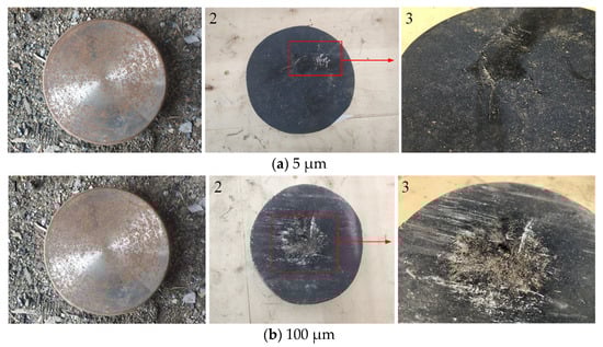
Figure 5.
Damage to the witness target.
As can be seen from the figure, the surface and both sides of the target are black. This may be caused by the deflagration products attached to the target surface. Secondly, observation can find that the witness target under the reactive liners of the two types are slightly damaged, leaving only small pits on the surface. Because the distance between the witness target and the liner is 4.0 CD, the damage ability of the jet has been greatly reduced as a result of expansion by chemical reaction before it arrives at the witness target. As can be seen from Figure 4, the number of pits on the witness target with the aluminum particle size of 100 μm is more than the number of pits on the witness target with the aluminum particle size of 5 μm, and the pits are concentrated in a certain range (damage area). When the aluminum particle size is 5 μm, the pit depth is very small, and the distribution is relatively scattered, almost distributed on the entire surface of the witness target.
According to the damage of the witness target, it is speculated that most of the RMs have reacted before the reactive jet reaches the witness target, and only a few unreacted materials hit the witness target, causing slight damage to the witness target. Secondly, a large amount of RMs inside the slug undergo a chemical reaction before reaching the witness target, and the remaining unreacted part is weak due to excessive divergence. This is because if most of the slug reacted after hitting the witness target, the damage effect will be larger than that shown in Figure 5. As shown in Figure 6, through high-speed photography, it was found that the final firelight was collected above the witness target, and there was still a certain distance from the witness target. This phenomenon indicates that the slug reacts without hitting the witness target plate, and if the slug reacts after hitting the witness target plate, the final firelight should appear at the witness target plate position.

Figure 6.
The position of firelight contraction. (▭:The target location).
In summary, the explosive energy is sufficient to cause the RMs reaction during the jet formation. This issue should be taken into account when studying PTFE/Al reactive jet formation.
3. The Numerical Simulation
In this paper, ANSYS Autodyn-3D is used to simulate the jet formation. The real-time reaction of the reactive jet and the energy loss can be clearly seen in the results. The SPH (Smoothed Particle Hydrodynamics) method was used to simulate the jet formation. Tunable ignition threshold and relevant material model were developed to recreate the impact-induced deflagration behavior of RMs in previous work, the details of which can be found in reference [18].
3.1. Finite Element Model
In order to reduce the computational cost, a three-dimensional 1/2 simulation model is established in this paper, as shown in Figure 7. The material of the liner is PTFE/Al and 8701 explosive was used as the main charge. The material of the witness target is 45# steel. SPH was used to fill the liner, explosive, and steel target. The central point initiation mode is adopted for detonation, and the initiation point is shown as the red dot in Figure 7. The structure of the liner adopts the conical structure with equal wall thickness; the wall thickness of the liner is 5 mm. In addition, Gaussian points named 1, 2, 3, and 4 are set on the liner to examine the history variables, where 1 and 2 are located on the inner layer of the liner, and 3 and 4 are located on the outer layer of the liner.

Figure 7.
3D simulation model.
3.2. Material Model
3.2.1. Constitutive Model
In this paper, the parameters of the Johnson–Cook constitutive model of PTFE/Al RM were determined by studying its dynamic and static mechanical properties. The Johnson–Cook constitutive model expression is as follows
where A is the yield stress, B and n are the strain hardening rate, C is the coefficient of strain rate sensitivity, ε is the strain rate, is the reference strain rate. Parameter A is obtained from the quasi-static compression experiment data. The values of A, B, n, and C were obtained by combining the SHPB experimental data; see References [19,20] for details. According to the experimental data, the parameters of the Johnson–Cook constitutive model of RMs prepared with Al particles with different particle sizes can be calculated, as shown in Table 1.

Table 1.
The parameters of the Johnson–Cook constitutive model.
According to the Johnson–Cook constitutive model of the RMs obtained, the nonlinear fitting was performed with the experimental data at different strain rates as variables, and the fitting curve is high consistent with the experimental curve, this is shown in Figure 8.
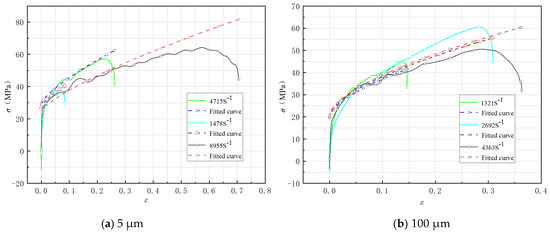
Figure 8.
Stress–strain curves under different aluminum particle sizes.
3.2.2. EOS Model
When a material is subjected to a high impact pressure, it can be treated approximately as a fluid. The famous Rankin–Hugoniot energy equation can be obtained from the three conservation equations governing fluid motion.
where the subscript “0” represents the initial state, E, P, and V are the specific internal energy, pressure, and specific volume of the material, respectively.
The relationship between material energy and pressure can be obtained from thermodynamic identity
If E = CVT, and the specific heat CV at constant volume is a constant or a function independent of the specific volume V, it can be obtained
The Grüneisen state equation of the material can be obtained by integrating Equation (4)
Equations (2) and (5) can be used to obtain the equation of state expression of the compacted material
where γ(V) is the Grüneisen coefficient, PC is the cold pressing of the materials, and EC is the cold energy of the materials.
The cold energy and cold pressing of materials are due to the interaction between crystals, and there are generally three potential functions used to describe them: the Born–Mayer potential, the Mie potential, and the Morse potential [21,22]. Among them, the Morse potential can better describe the cold pressing and cold energy curves of the material, and the equation is
where A, B are the parameters measured by the test, and δ = V0K/V is the compressibility of the material at zero temperature.
On the basis of the above equations, the cold energy superposition principle is selected to calculate the cold pressing line of the mixture, and the Hugoniot relationship of the mixture is further calculated. The specific volume and specific internal energy of the mixture are
where mi is the percentage of mass of the group i, and Vi and Ei are the specific volume and specific internal energy of the group i, respectively. Similarly, the initial parameters of the mixture material can be obtained through the superposition principle
According to the three conservation equations of solid materials, the expressions of shock wave velocity US and particle velocity UP with respect to P and V can be obtained
And the relation between the shock wave velocity and the particle velocity is
where C0 is the sound velocity of the material and S is the material proportion coefficient.
Firstly, the cold energy value of the mixture is calculated according to the cold energy superposition method, the material constants A and B are fitted by the relationship curve of EC—V, and the A and B values of the mixture are substituted into Equations (7)–(9) to obtain the cold energy EC, cold pressed PC and γ(V) of the mixture. Then, the values of these three parameters can be substituted into Formula (6) to obtain the mixture material and the P-V relationship. Finally, the P-V relationship of the material was substituted into Equations (13)–(15) to obtain the initial material parameters US, UP, and γ0 of the mixture. By fitting Equation (16), the material sound velocity C0 and the scaling coefficient S can be obtained. The initial material parameters of the elemental material and the final calculated equation of state parameters of the PTFE/Al RMs are listed in Table 2.
Table 2.
The parameters of elemental materials.
3.2.3. The Material Models of Explosive and Target Plates
In the paper, the explosive used was 8701 and the JWL EOS model was used in the numerical model of explosive. The model parameters are shown in Table 3. The target was made of 45# steel. The shock EOS model and Johnson–Cook strength model were used in the numerical model of the explosive. The model parameters are shown in Table 4.
Table 3.
The material parameters of the explosive.
Table 4.
The material parameters of the target.
4. Results and Discussion
4.1. The Morphology Reactive Shaped Charge Jets
Through the simulation, the morphological characteristics of reactive shaped charge jets of PTFE/Al liner prepared with aluminum powder with two particle sizes were obtained. Figure 9 shows the formation of two reactive shaped charge jets. The color isoline on the right of the figure is used to indicate the reaction degree of the RMs during the jet formation. As can be seen from the figure, during the jet formation, the jet formed by the liner prepared with 5 μm aluminum powder reacted earlier than 100 μm aluminum powder, and both jet heads reacted first. Within 0.0 CD~1.5 CD of stand-offs, the jet head with 5 μm aluminum particle size is more divergent, but the morphology of the two slugs is similar. At 1.5 CD from stand-offs, the slug with 5 μm aluminum powder has an obvious reaction. For the 100 μm aluminum powder, the internal reaction of the slug was obvious only when the jet reached 2.0 CD from stand-offs. The jet morphologies of the two are obviously different when the stand-offs are 2.0 CD. The expansion rate of the slug corresponding to 100 μm aluminum powder is smaller than that of 5 μm aluminum powder, and its jet head is more condensed. Secondly, it can be seen from Figure 9 that the slug of the reactive shaped charge jet has already started to react before it reaches the target. The reaction is violent, and the RMs have a high degree of reaction. The phenomenon is consistent with the firelight captured by high-speed photography, as the firelight finally collects above the target.

Figure 9.
The formation of reactive shaped charge jet.
The main reason for the above phenomenon is that the smaller the size of the aluminum particles, the more easily the RMs react [15,16]. During the jet formation, the liner with small Al particles has the largest specific surface area. With the same mass, the larger the specific surface area, the greater the friction area, thus generating more heat. In addition, the strain rate constant of the RMs prepared with the two kinds of Al particles is significantly different. The strain rate constant of the RMs prepared with the 5 μm Al particles is twice that the strain rate constant of the RMs prepared with the 100 μm Al particles. The higher the strain rate constant is, the more energy is absorbed per unit volume during the jet formation, and the faster the RMs reach the reaction condition. Secondly, Al particle size has an influence on the destruction mode of the RMs, and during the reaction of the RMs, gases were generated. Therefore, the reactive shaped charge jet formed by the 5 μm aluminum liner reacts earlier, and the jet head and the slug are thicker.
During the jet formation, the top of the liner is first subjected to the blast pressure to form a jet, so the jet head begins to react first. Due to the convergence of the inner layer of the liner during the jet formation, the chemical reaction of the jet is from inside to outside. Figure 10 shows the pressure change at Gauss points during the jet formation. Gauss points 1 and 2 are located in the inner layer of the liner, and Gauss points 3 and 4 are located in the outer layer of the liner. It can be seen from Figure 10 that during the jet formation, the pressure on the inner layer of the liner rose sharply, reached a peak value, and then began to decline gradually. After reaching the first peak, the inner layer pressure of the liner decreased rapidly, and then increased rapidly after about 2.5 μs, reaching the second peak, and the second peak value was higher than the first peak value. The appearance of a secondary peak indicates that the RMs in the inner layer of the liner have indeed undergone a secondary collision.
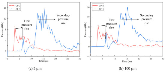
Figure 10.
Gauss point pressure curve.
As mentioned above, in this paper, the morphology of reactive shaped charge jet formed by the liner prepared with two aluminum particle sizes were obtained by X-ray photography technology, namely, group (a) aluminum particle size was 5 μm, and the measured time was 19.1 μs and 29.8 μs; group (b) aluminum particle size was 100 μm, measured time 18.9 μs and 29.9 μs. Figure 11 shows the comparison between X-ray images and simulated images of the reactive jet.
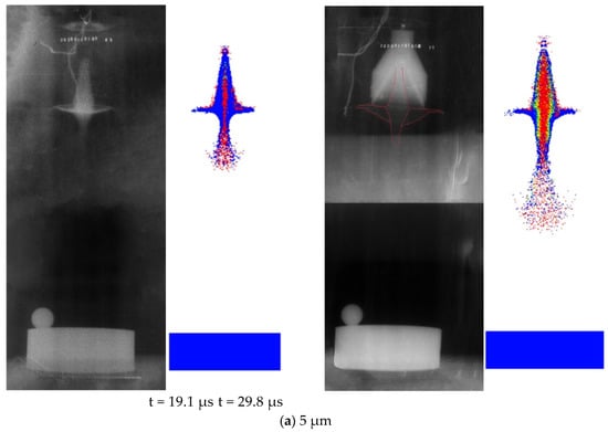
Figure 11.
Shape contrast of shaped charge penetration.
According to the comparison of Figure 11, it can be seen that there is a high degree of similarity between the simulation results and experimental results. Table 5 shows the comparison between the simulation jet size and experimental jet size.
Table 5.
The size of reactive jet.
As can be seen from the data in Table 5, the errors between the simulation results and those measured in the experiment are within the range of 4%~8%, and all the errors are within a reasonable range. This data indicates that the simulation results in this paper are highly reliable.
4.2. Reaction Degree and Jet Velocity during the Jet Formation
Reaction degree and jet velocity are two important factors affecting the damage ability of shaped charge jets. In this paper, the energy loss was qualified through the reaction degree of the RMs during the jet formation. The reaction degree of the RMs prepared with two aluminum particle sizes was obtained through numerical simulation, as shown in Figure 12. Points 1~8 in the figure indicate the reaction degree of the jet when the jet head reached 0.5 CD, 1.0 CD, 1.5 CD, 2.0 CD, 2.5 CD, 3.0 CD, 3.5 CD, and 4.0 CD.
Figure 12.
Reaction degree of reactive materials.
In order to obtain the reaction degree of the RMs during the jet formation, a subroutine that executed at the end of every calculation circulation is compiled. The reaction degree of RMs is defined as
where mi denotes the mass of every particle contained in RMs and αi is the corresponding reaction ratio of the particles. Then, the reaction degree of the reactive jet can be calculated.
According to Figure 9 and Figure 12, the chemical reaction of the RMs during the jet formation can be divided into two stages: (1) The local reaction stage induced by shock wave, in which the reaction is mainly concentrated in the jet head; (2) Overall reaction stage, in which the reaction is concentrated in the slug. In the local reaction stage, the reaction of the RMs is relatively mild, but in the overall reaction stage, the deflagration of RMs is violent, and the reaction degree increases extremely. It can be found that when the aluminum particle size is 5 μm, the RMs enter the local reaction stage at about 3 μs, while when the aluminum particle size is 10 0 μm, the RMs enter the local reaction stage at about 8 μs. Correspondingly, the time for the RMs to enter the overall reaction stage with a particle size of 5 μm is also about 10 μs faster than 100 μm. Secondly, in the local reaction stage, the highest reaction degree of 5 μm aluminum particle size was about 4.5%, while the reaction degree of 100 μm aluminum particle size was less than 1%.
As shown in the figure, the final reaction degree of 5 μm aluminum particle size is about 60%, while that of 100 μm aluminum particle size is about 80%. The reason may be that the rapid reaction of the inner RMs leads to the rapid expansion of the shaped charge jet volume, which makes the jet too divergent, and the stress on the outside fails to meet the ignition conditions of the RMs. Secondly, when the aluminum particle size is 5 μm, more AlF3 is generated in the initial reaction, and the gasification of AlF3 will absorb a lot of heat, so that the PTFE can’t reach the decomposition temperature. Therefore, the final reaction degree of the RMs prepared with 5 μm aluminum particle size is less than that the RMs prepared with 100 μm aluminum particle size.
According to Figure 12, the reaction degree and reaction rate of the two types of shaped charge jets can be deduced as shown in Table 6.
Table 6.
Reaction rate of shaped charge projectiles during molding.
Figure 13 shows the velocity contour at 4.0 CD during the jet formation and the velocity curve of the main part of the jet. The velocity curves of the jet head, the middle of jet, and slug positions in Figure 13b,d correspond to 1, 2, and 3 in Figure 13a,c, respectively.
Figure 13.
Velocity of shaped charge projectiles.
As can be seen from the figure, when the jet head reaches 0.5 CD, the jet head velocity under the two aluminum powder particle sizes reaches about 7800 m/s at about 20 μs. When the jet head reaches 1.5 CD, the velocity of the middle of jet reaches its maximum velocity at around 30 μs, about 4800 m/s.
It can be seen from the above that during the jet formation the reaction firstly concentrates on the jet head. Therefore, although the jet head has a high penetration speed, the penetration ability of the head on the target will be greatly weakened due to its excessive reaction. This is also the reason why the penetration depth of reactive shaped charge jets is smaller than that of inert shaped charge jets. For reactive shaped charge jet, the penetration depth mainly depends on the middle of the jet.
Considering the reaction degree and jet velocity, combined with Figure 12 and Figure 13, it can be concluded that when the aluminum particle size is 5 μm, the optimal stand-off is between 0.5 CD and 1.0 CD. When the aluminum particle size is 100 μm, the optimal stand-off is between 1.0 CD and 1.5 CD.
5. Conclusions
In this paper, the X-ray photography experiment of reactive shaped charge jet formation was performed on PTFE/Al liners prepared with two aluminum particle sizes (5 μm and 100 μm). The secondary development technology was used to simulate the formation of PTFE/Al reactive shaped charge jets and compared with the experimental results. By analyzing the experimental phenomenon and simulation results, the following conclusions were obtained:
- (1)
- The RMs reacted during the PTFE/Al reactive shaped charge jet formation, which can be divided into local reaction stage and overall reaction stage. In the local reaction stage, the reaction is relatively mild and mainly concentrated in the jet head. In the whole reaction stage, the RMs deflagrate violently, and the reaction mainly concentrates in the slug.
- (2)
- Secondary collision occurs in the inner layer of the liner during the jet formation, and the pressure generated by the secondary collision is higher than that given by the explosive. Therefore, the reaction of PTFE/Al reactive shaped charge jet is from inside to outside during the jet formation.
- (3)
- The effect of Al particle size on the mechanical properties and reaction rate of PTFE/Al RMs are the main reason for the formation of the difference during the jet formation. Compared with the 5 μm aluminum powder, the PTFE/Al reactive liner prepared with 100 μm aluminum powder reacted slowly and the morphology of jet is more condensed, which is conducive to generating greater penetration depth.
Author Contributions
Conceptualization, H.W.; Data curation, M.G.; Formalanalysis, Y.W. and J.X.; Funding acquisition, H.W. and J.X.; Investigation, Y.C.; Methodology, H.W.; Project administration, J.X.; Resouces, H.W.; Software, M.G., Y.W. and J.X.; Supervision, H.W. and J.X.; Validation, Y.C. and H.W.; Visualization, Y.C.; Writing—original draft, M.G. and Y.W.; Writing—review & editing, M.G. and Y.W. All authors have read and agreed to the published version of the manuscript.
Funding
The research was funded by the National Natural Science Foundation of China (Grant No.11702256), Natural Science Foundation of Shanxi Province (Grant No.20210302124214).
Data Availability Statement
The data that support the findings of this study are available from the corresponding author upon reasonable request.
Conflicts of Interest
The authors declare that they have no known competing financial interests or personal relationships that could have appeared to influence the work reported in this paper.
References
- Yi, J.; Wang, Z.; Yin, J.; Zhang, Z. Simulation Study on Expansive Jet Formation Characteristics of Polymer Liner. Materials 2019, 12, 744. [Google Scholar] [CrossRef] [PubMed] [Green Version]
- Zheng, Y.; Su, C.; Guo, H.; Yu, Q.; Wang, H. Behind-Target Rupturing Effects of Sandwich-like Plates by Reactive Liner Shaped Charge Jet. Propellants Explos. Pyrotech. 2019, 44, 1400–1409. [Google Scholar] [CrossRef]
- Herbold, E.B.; Nesterenko, V.F.; Benson, D.J.; Cai, J.; Vecchio, K.S.; Jiang, F.; Addiss, J.W.; Walley, S.M.; Proud, W.G. Particle size effect on strength, failure and shock behavior in Polytetrafluoroethylene-Al-W granular composites. J. Appl. Phys. 2008, 104, 1007. [Google Scholar] [CrossRef]
- Ames, R.G. Vented chamber calorimetry for impact-initiated energetic materials. In Proceedings of the 43rd AIAA Aerospace Sciences Meeting and Exhibit, Reno, NV, USA, 10–13 January 2005; pp. 15391–15403. [Google Scholar] [CrossRef]
- Rosencrantz, S.D. Characterization and Modeling Methodology of Polytetrafluoroethylene Based Reactive Materials for the Development of Parametric Models. Master’s Thesis, Wright State University, Dayton, OH, USA, 2007. [Google Scholar]
- Baker, E.L.; Daniels, A.S.; Ng, K.W.; Martin, V.; Orosz, J. Barnie: A unitary demolition warhead. In Proceedings of the 19th International Symposium on Ballistics, Interlaken, Switzerland, 7–11 May 2001; pp. 569–574. [Google Scholar]
- Daniels, A.S.; Baker, E.L.; Defisher, S.E.; Ng, K.W.; Pham, J. BAM: Large scale unitary demolition warheads. In Proceedings of the 23rd International Symposium on Ballistics, Tarragona, Spain, 16–20 April 2007; pp. 239–246.
- Xiao, J. Research on Damage Effects of Multi-layered Concrete Targets Impacted by Explosively Formed Penetrato. Ph.D. Thesis, Beijing Institute of Technology, Beijing, China, 2016. [Google Scholar]
- Zhang, X.-P.; Xiao, J.; Yu, Q.-B.; Zheng, Y.-F. Armor penetration aftereffect overpressure produced by reactive material liner shaped charge. Acta Armamentarii 2016, 37, 1388–1394. [Google Scholar]
- Zhang, X.; Xiao, J.; Yu, Q.; Wang, H. Penetration and blast combined damage effects of reactive material jet against steel target. Trans. Beijing Inst. Technol. 2017, 37, 789–793. [Google Scholar]
- Wang, Y.; Yu, Q.; Zheng, Y.; Wang, H. Formation and Penetration of Jets by Shaped Charges with Reactive Material Liners. Propellants Explos. Pyrotech. 2016, 41, 618–622. [Google Scholar] [CrossRef]
- Guo, H.; Zheng, Y.; Yu, Q.; Chao, G.; Wang, H. Penetration behavior of reactive liner shaped charge jet impacting thick steel plates. Int. J. Impact Eng. 2018, 126, 76–84. [Google Scholar] [CrossRef]
- Guo, H.; Lu, G.; He, S.; Wang, H.; Xiao, Y.; Zheng, Y. Penetration enhancement behavior of reactive material double-layered liner shaped charge. Trans. Beijing Inst. Technol. 2020, 40, 1259–1266. [Google Scholar]
- Li, Y.; Wang, W.; Zhang, L.; Jiang, C. Research on jet coherency of PTFE-based energetic liner. Acta Armamentarii 2019, 40, 2433–2439. [Google Scholar]
- Liu, Y.; Ren, H.; Li, W.; Ning, J. Influence of Particle Size of Aluminum Powder and Molding Pressure on Impact-Initiation of Al/PTFE. Chin. J. High Press. Phys. 2019, 33, 123–130. [Google Scholar]
- Mao, L.; Wei, C.; Hu, R.; Hu, W.; Luo, P.; Qi, Y.; Jiang, Y. Effects of Al Particle Size on the Impact Energy Release of Al-Rich PTFE/Al Composites under Different Strain Rates. Materials 2021, 14, 1911. [Google Scholar] [CrossRef] [PubMed]
- Zhou, J. Study on the Impact-Induced Reaction Characteristics of Typical Fluoropolymer-Matrix Reactive Materials. Ph.D. Thesis, Nanjing University of Science and Technology, Nanjing, China, 2018. [Google Scholar]
- Xiao, J.; Wang, Y.; Zhou, D.; He, C.; Li, X. Research on the Impact-Induced Deflagration Behavior by Aluminum/Teflon Projectile. Crystals 2022, 12, 471. [Google Scholar] [CrossRef]
- Xiao, J.; Wang, Z.; Nie, Z.; Tang, E.; Zhang, X. Evaluation of Hugoniot parameters for unreacted Al/PTFE RMs by modified SHPB test. AIP Adv. 2020, 10, 045211. [Google Scholar] [CrossRef]
- Wang, Z. Parameter Calibration of PTFE/Al RMs and Numerical Simulation Research of Its Impact-Induced Deflagration Behavior. Master’s Thesis, North University of China, Taiyuan, China, 2021. [Google Scholar]
- Tang, W.; Zhang, R. Introduction to Theory and Computation of Equations of State; Higher Education Press: Beijing, China, 2008. [Google Scholar]
- Queen, G.M.; Marsh, S.P.; Taylor, J.W.; Cable, A.J.; Dienes, J.K.; Walsh, J.M.; Carter, W.J.; Fritz, J.N.; Gehring, J.W.; Glass, C.M.; et al. High Velocity Impact Phenomena; Academic Press: New York, NY, USA, 1970. [Google Scholar]


Publisher’s Note: MDPI stays neutral with regard to jurisdictional claims in published maps and institutional affiliations. |
© 2022 by the authors. Licensee MDPI, Basel, Switzerland. This article is an open access article distributed under the terms and conditions of the Creative Commons Attribution (CC BY) license (https://creativecommons.org/licenses/by/4.0/).