Article

Microstructure and Mechanical Properties of the Ternary Gas Shielded Narrow-Gap GMA Welded Joint of High-Strength Steel

1
State Key Laboratory of Advanced Welding and Joining, Harbin Institute of Technology, Harbin 150001, China
2
State Key Laboratory of Metal Material for Marine Equipment and Application, Anshan 114000, China
*
Authors to whom correspondence should be addressed.
Crystals 2022, 12(11), 1566; https://doi.org/10.3390/cryst12111566
Submission received: 14 October 2022 / Revised: 28 October 2022 / Accepted: 1 November 2022 / Published: 3 November 2022
(This article belongs to the Special Issue Physical Mechanism of Welding of Metallic Materials)

Abstract

:
An 80%Ar-10%CO2-10%He ternary gas mixture was used as the shielding gas during the narrow-gap welding of thick Q690E high-strength steel plates. Complete and defect-free welded joints were obtained, and the microstructure and mechanical properties of the welded joint were investigated. The weld zone consists of a solidification area and interlayer zone, and the heat-affected zone consists of a coarse-grain heat-affected zone (CG-HAZ) and a fine-grain heat-affected zone (FG-HAZ). The microstructures of the weld zone are mainly lath bainite (LB), acicular ferrite (AF), and granular bainite (GB). The microstructure of the CG-HAZ is lath martensite (LM) and the microstructure of FG-HAZ is GB. Methods with different heat inputs were used to study their effects on the mechanical properties of the welded joint. It was found that the microstructure and mechanical properties of the welded joints are better with lower heat input. With tandem wire narrow-gap GMA welding, the tensile strength of the joints declined from 795.3 to 718.3 MPa and the impact toughness at −40 °C resulted in a weak position in the weld zone, which declined from 76~81 J to 55~69 J, when the welding speed reduced from 350 to 250 mm/min. With oscillating-arc narrow-gap GMA welding, the tensile strength achieved 853.4 MPa and the impact toughness at −40 °C was around 69~87 J. The results indicated that, under the appropriate heat input, the tensile strength of the joint exceeds 770 MPa and the low temperature impact toughness at −40 °C exceeds 69 J. A 155 mm-thick Q690E steel welded joint was obtained and the mechanical properties of the welded joint meets the requirements of the offshore drilling platforms.

1. Introduction

As the main load-bearing structure of the offshore drilling platform, the pile legs not only have to bear the gravity of the main structure of the drilling platform above the sea surface, but also have to withstand the corrosion of sea water, the impact of ocean currents, and the strong external force of seabed earthquakes for a long time during the whole service period [1,2,3,4]. Therefore, in the construction of the entire offshore platform, the construction quality of the pile legs is of great significance to the safety and service life of the entire offshore platform. The tensile strength of the welded joints in the pile legs is required to be greater than 770 MPa, and the low-temperature impact energy at −40 °C is required to be greater than 69 J [5]. Q690E high-strength steel is widely used as the structural material of pile legs because of its high strength and low ductile–brittle transition temperature [6].
Q690 grade steel is a kind of high-strength steel, whose microstructures consist of bainite and martensite. Its strength level is around 700 MPa. In recent years, two developed methods for 690 MPa grade have been commonly used: quenching and tempering, and the thermomechanical control process [7,8]. Q690 steels perform well as a structural material. However, some problems exist when Q690 steels are treated as a welding structure. Q690 steels have a tendency to cold crack, and thus need preheating during the welding process [9,10]. At present, the thickness and length of Q690E steel for pile legs of drilling platforms have reached 178 mm and 167 m, respectively. The current welding methods for Q690E thick plates are shielded metal arc welding (SMAW), gas metal arc welding (GMAW), and submerged arc welding (SAW), and a wide-open groove is used to ensure the welding quality. SMAW and conventional GMAW cost a large sum in terms of welding materials and processing time, while SAW causes a significant decrease in the mechanical properties in CG-HAZs because of its high heat input [11]. An efficient welding method with high quality is needed.
In narrow-gap welding of thick plates, a deep and narrow gap is used as the groove instead of the traditional wide-open groove. Therefore, narrow-gap welding has a higher welding efficiency, and it also requires less filler metal [12,13,14,15,16]. However, the lack of sidewall fusion is the most frequent defect in narrow-gap welding due to the small included angle between the electrode and the sidewall [14]. Some advanced welding techniques were developed to expand the arc heating area and increase heat transfer to the sidewall, which can ensure the sufficient sidewall penetration, such as rotating-arc welding [17,18,19,20], swinging-arc welding [21,22,23,24], and tandem welding [25]. During the welding process, the shielding gas is ionized to form the arc. Therefore, the physical properties of the shielding gas will directly affect the heat transfer in the arc. Helium has special physical properties, such as a higher thermal conductivity and ionization energy. Hence, more heat could be transferred to the edge of the arc, which is beneficial to the sidewall penetration in narrow-gap welding. In our previous studies, it was found that the sidewall penetration can be increased by up to 40% with the addition of 10% helium to the Ar-CO2 gas [26].
In this study, the 80%Ar-10%CO2-10%He ternary shielding gas mixture was used as the shielding gas to weld thick Q690E high-strength steel. The microstructure and mechanical properties of the welded joint under different welding heat inputs were investigated, and a welded joint with excellent properties was obtained with appropriate heat input.

2. Experimental Materials, and Methods

During the tandem narrow-gap welding process, the two wires were controlled independently by two CLOOS 503 power sources. As shown in Figure 1, the ends of the two contact tips were bent to direct the two wires toward the opposite sidewalls to ensure sufficient sidewall penetration, and the bending angle was 7°. The distance between the two wires was 8 mm, and the two arcs were attached to one single molten pool.
During the swing-arc narrow-gap welding process, the arc and wire swing in the narrow-gap groove as the contact tip rotates back and forth. As given in Figure 1, the contact tip is screwed into the lower part of conducting rod, which is bent to form an angle of 7°. The wire is fed through the inner hole of the conducting rod and stretches out from the contact tip so an angle of 7° is formed between the wire and the axis of the conducting rod. The conducting rod is driven by a motor.
All power sources were operated in pulsed mode, in which the peak voltage and the base current were both held constant. ESAB OK AristoRod 69 welding wire with a diameter of 1.2 mm was used as the filler metal. No preheating was used before welding. The 80%Ar-10%CO2-10%He (vol.%) gas mixture with a flow of 40 L/min was used as the shielding gas.
The composition of Q690 base metal and the wire used in our work are shown in Table 1 and Table 2.
The cross-sectional and metallographic samples were ground and polished, and finally etched using saturated FeCl3 aqueous solution. The welded joint morphology and microstructure were examined with a Keyence VHX-1000E optical microscope (OM). The room temperature tensile strengths of the welded joint were tested on an Instron-5569 electronic universal testing machine, and the loading speed was 2.0 mm/min. Charpy impact tests were carried out to study the low-temperature impact toughness of the welded joint. During the test, the sample was placed in a liquid nitrogen refrigerator. When the temperature of the test sample reached −40 °C, the sample was quickly taken out and placed in the sample slot of the impact tester; then, the suspended pendulum was released to impact the sample to obtain the impact energy. A V-notch was made at the weld center, fusion line, and heat-affected zone, 2 mm outside from the fusion line. For thick plates, in order to make the test results more comprehensive, the tensile strength and the impact toughness at different positions along the weld thickness direction should be investigated. The sampling positions are shown in Figure 2.
Tandem narrow-gap welding was used first, and the effects of heat input were studied. The welding parameters are given in Table 3, and three different welding speeds were chosen to achieve different magnitudes of heat inputs.
A double-side narrow-gap groove was also used. During the welding process, when two layers at one side were completed, two layers on the other side were welded. The parameters are given in Table 4.

3. Results and Discussion

3.1. Effects of Heat Input on the Microstructure and Mechanical Properties

As shown in Figure 3, three complete and defect-free welded joints were obtained. The sidewalls had sufficient penetrations. When the welding speed was 250 mm/min, seven layers were needed to fill the gap; when the welding speed increased to 300 or 350 mm/min, eight filling layers were needed. This indicates that preheating is not required in narrow-gap welding of Q690E steel thick plates. The narrow and deep groove can confine the welding heat in the groove and reduce the cooling rate of the weld bead, which can prevent the cold cracks.
Generally, martensite, bainite, and ferrite exist in the low carbon micro-alloyed system, and Q690 grade TMCP steels belong to this alloy system [27]. In addition, these kinds of phases could be distinguished through morphological features by optical microscope [28]. Figure 4, Figure 5 and Figure 6 show the microstructure of the typical zones in the welded joints. Welded joints mainly include the base metal zone, heat-affected zone (HAZ), and weld zone (WZ). The heat-affected zone contains the coarse-grain zone (CG-HAZ) and fine-grain zone (FG-HAZ). The weld zone also contains the interlayer zone. Different regions present different microstructures. The microstructure of CG-HAZ is mainly lath martensite (LM); the microstructure of FG-HAZ is finer granular bainite (GB); the microstructure of WZ is acicular ferrite (AF) and a small amount of granular bainite (GB); the microstructure of the interlayer in the WZ contains acicular ferrite (AF), lath bainite (LB), and granular bainite (GB) in the original austenite grain, and fine secondary austenite decompositions along the grain boundaries of the original austenite grain.
With the increase in the welding heat input, the grain size in the CG-HAZ gradually increases. In the WZ, the morphology of bainitic ferrite changes from AF to LB with the increase in heat input. When the welding speed decreases to 250 mm/min, there is little AF content in the WZ, and the microstructure is dominated by LB. In the interlayer, the content of fine secondary austenite decompositions increases as the heat input increases.
The tensile strengths of the welded joints are given in Table 5. It can be seen that the tensile strength increases as the heat input decreases; when the welding speed reaches 350 mm/min, the tensile strength of the three samples exceeds 770 MPa. It was found that all the samples were broken at the weld zone, which indicates that the weld zone is the weak part of the welded joint. The tensile strengths were approximately similar to the strengths of Xu et al. [29], while the strengths under proper welding speeds were higher in our work.
The impact toughness of the welded joints is given in Table 6. The upper (U), middle (M), and bottom (B) positions were tested. The HAZ has the highest impact toughness, and the weld zone has the lowest impact toughness. When the welding speed was 250 mm/min, the impact toughness of the upper and middle part of the welded joint did not reach 69 J. When the welding speed increased to 300 and 350 mm/min, the impact toughness of all the samples exceeded 69 J.
The impact toughness of the fusion zone and the HAZ decrease as the heat input increases. The grain size of the CG-HAZ increases as the heat input increases. Therefore, the impact toughness decreases. However, it can be seen that the impact toughness of the fusion zone and HAZ is much greater than 69 J, and the weak part is still the weld zone.
The weld zone contains GB, AF, and LB, and as the heat input increases, the content of the LB increases. The formation temperature of LB is above 600 °C, while the formation temperature of AF is around 500 °C. When the welding heat input is too large, the high-temperature residence time of the metal increases, which promotes the formation of LB and thus causes a significant reduction in the AF content. It is generally believed that a larger grain orientation difference tends to more significantly prevent cracking. Commonly, interfaces of lath bainite are large angle grain boundaries [30,31,32]. Nevertheless, the effective grain size of LB depends on the size of the lath bundle, while the effective grain of AF is the AF grain itself. In addition, interfaces of acicular ferrite are all large angle grain boundaries [33,34]. Thus, AF grains appear to be more effective for preventing cracking than LB lath bundles. A higher heat input causes the reduction in the AF content, which leads to the reduction in tensile strength of the welded joint and the impact toughness of the weld zone.

3.2. Microstructure and Mechanical Properties of the Welded Joint of Extra-Thick Q690E Steel Plate

It can be seen from the above results that the microstructure of the welded joint is seriously affected by the welding heat input. The mechanical properties of the welded joints reduce as the heat input increases. Therefore, relatively low welding heat input should be used in order to obtain better microstructure and mechanical properties. Xu et al. [24] found that the effective heat input in swing-arc narrow-gap welding is reduced as compared to non-oscillating welding with a V-type groove. Therefore, swing-arc narrow-gap welding was used in 155 mm-thick Q690E steel.
The welded joint was obtained by filling 34 layers. As presented in Figure 7, the joint was defect-free, and the weld appearance and weld profile were both good. Although the welding heat input is lower using a swing arc, the addition of helium promotes the heat transfer to the sidewall and the penetration is ensured.
The microstructure of the typical zone of the welded joint is shown in Figure 8. It can be seen that the weld zone is composed of AF; the microstructure of CG-HAZ is still mainly lath martensite (LM), but the grain size significantly decreases compared with that of tandem welding.
The mechanical properties of the welded joint were also tested. Table 7 shows the tensile strength of the welded joints from the upper position to the bottom position. It was found the average tensile strength of each sample exceeds 835.4 MPa, and the value is higher than that of the tandem welded joint. The tensile strength of the swing-arc narrow-gap welding joints in our work was similar to the results of Cai et al. [35]. Table 8 shows the impact toughness of the welded joints at −40 °C, and indicates that the low-temperature impact toughness of each position of the welded joint was above 69 J.

4. Conclusions

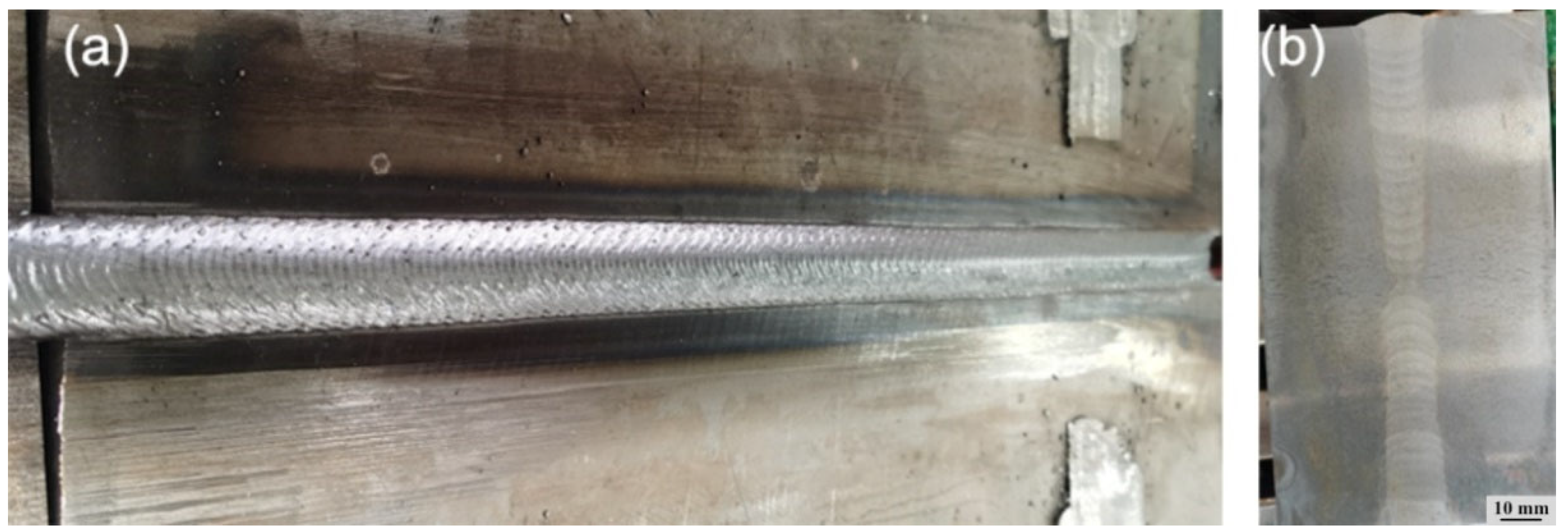
  • The completed narrow-gap welded joint of Q690E high-strength steel with sufficient sidewall penetration can be obtained using 80%Ar-10%CO2-10%He ternary shielding gas. Preheating before welding was not used.
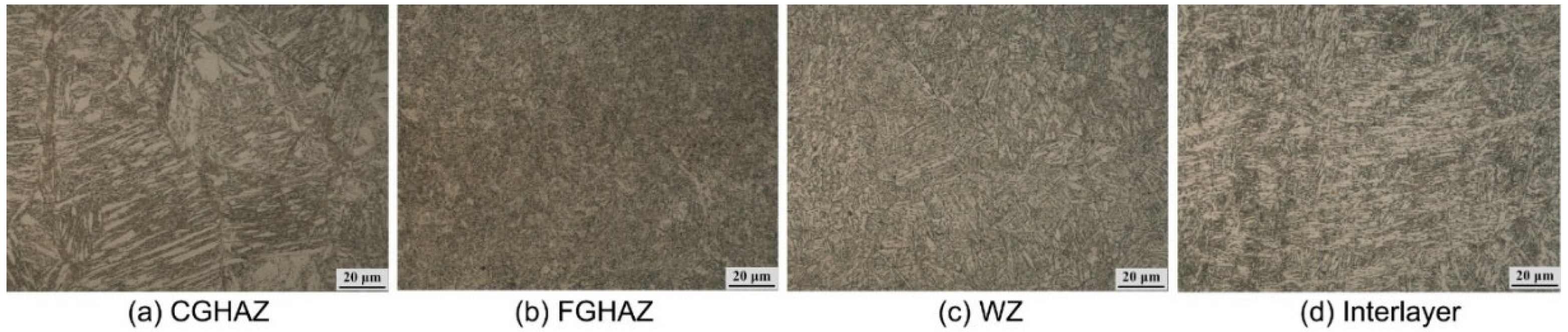
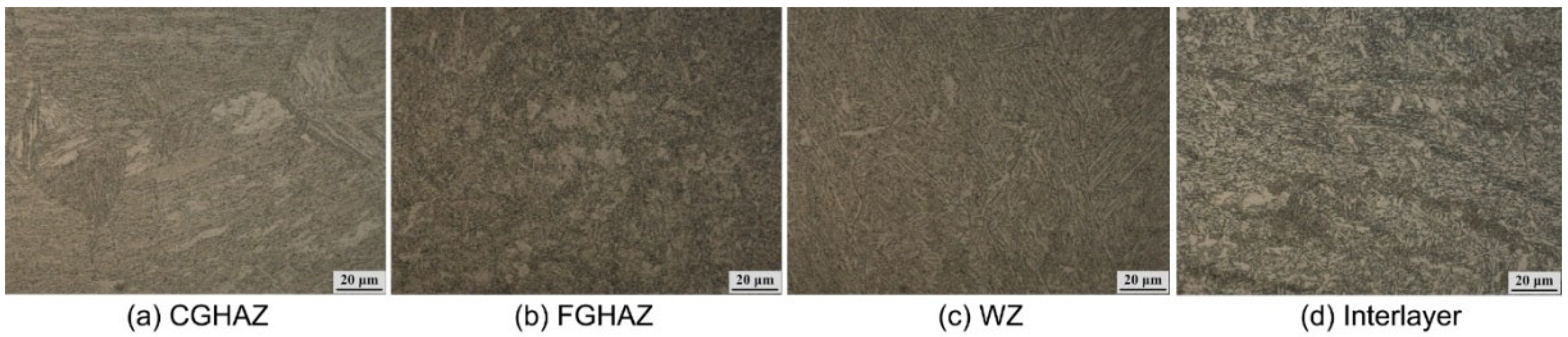
  • The welding heat input affects the microstructure and mechanical properties of the welded joint. As the heat input increases, the morphology of bainitic ferrite changes from AF to LB, which leads to the decrease in the tensile strength and low-temperature impact toughness of the welded joint. The grain size of the heat-affected zone increases with the increase in the heat input.
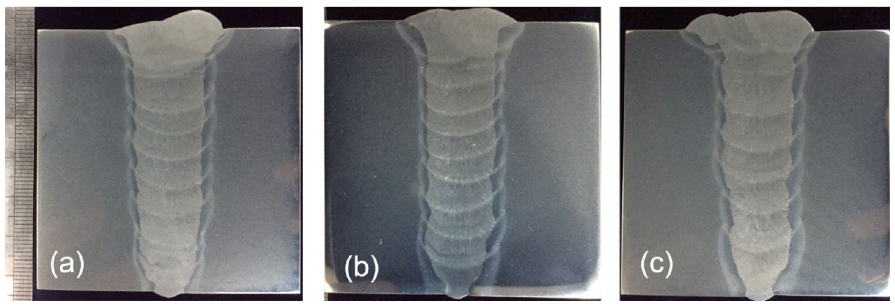
  • The tensile strength of the tandem wire narrow-gap GMA welding joints could be improved by optimizing the heat input through changing the welding speed. The average tensile strength was 795.3 MPa with a welding speed of 350 mm/min.
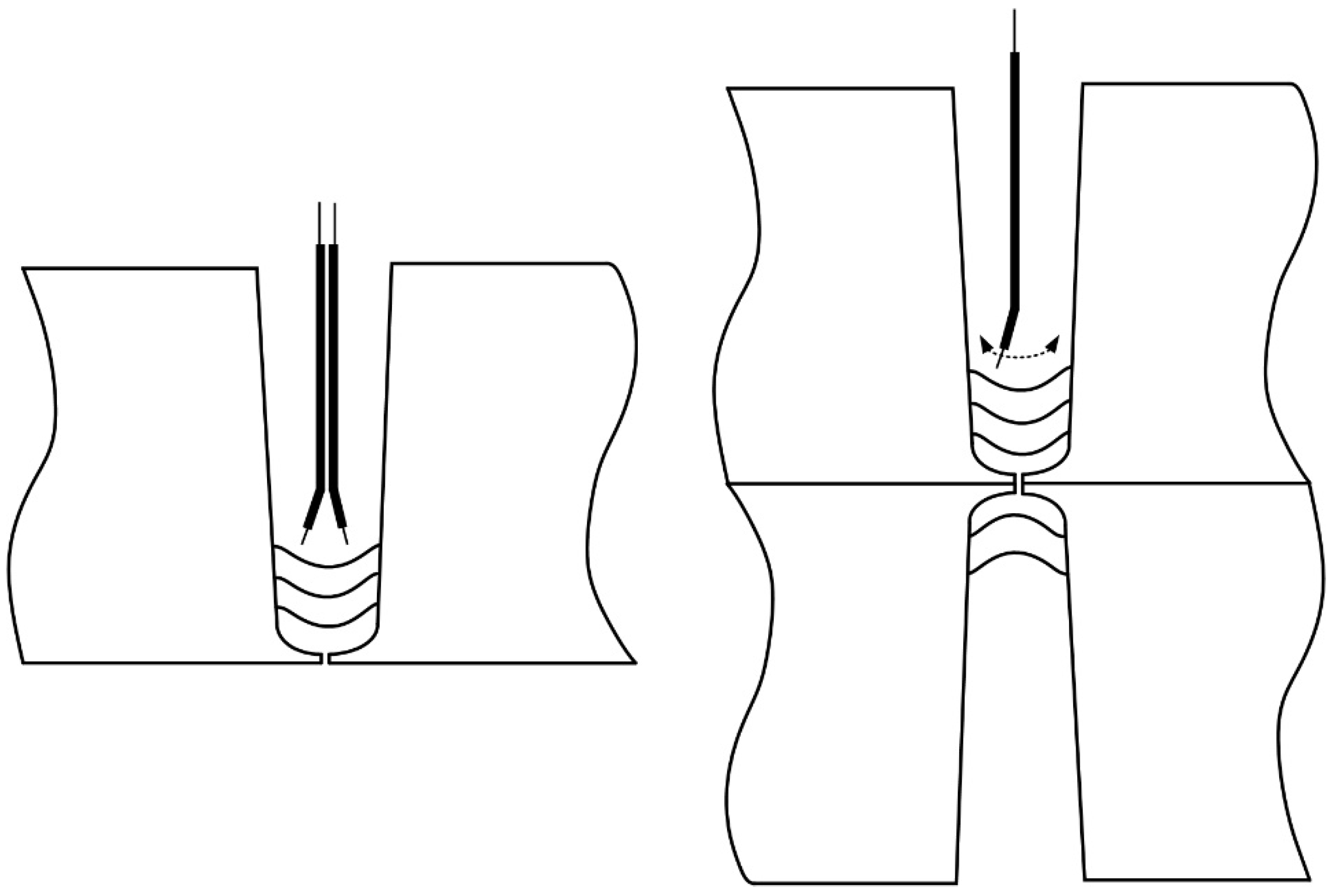
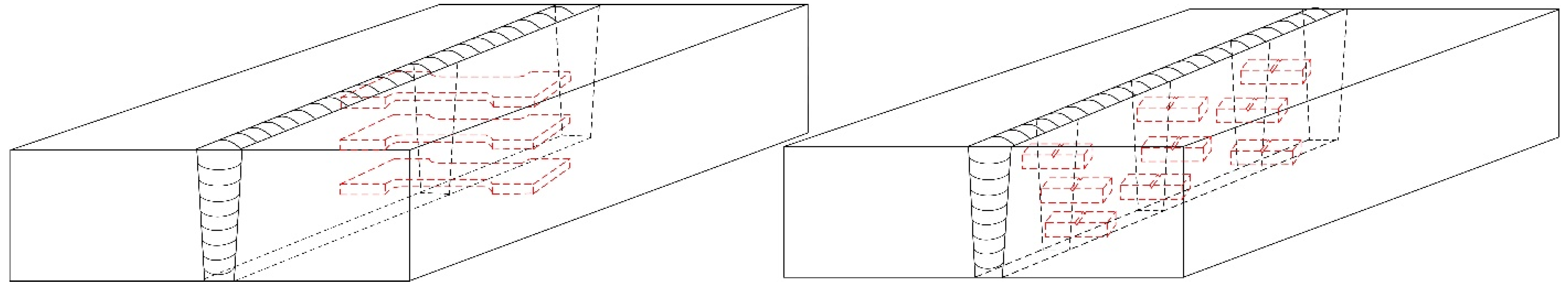
  • Swing-arc narrow-gap welding provides a lower heat input and the microstructure of the welded joint was further improved. Mechanical properties of swing-arc narrow-gap GMA welding joints were better than those of tandem wire narrow-gap GMA welding joints. A 155 mm-thick plate was welded using a double-sided groove. Complete welded joints were obtained and the average tensile strength of the welded joint exceeded 835.4 MPa, and the low-temperature impact toughness at −40 °C exceeded 69 J, which meets the service requirements.

Author Contributions

Conceptualization, S.L. and X.C.; formal analysis, Z.N.; resources, F.H.; data curation, Z.N., F.H. and Y.L.; writing-original draft preparation, Z.N.; writing -review and editing, X.C.; supervision, S.L.; funding acquisition, X.C. All authors have read and agreed to the published version of the manuscript.

Funding

This work was supported by the National Natural Science Foundation of China [grant number 51905128]. the Open Project Program of the State Key Laboratory of Metal Material for Marine Equipment and Application [grant number SKLMEA-K202005].

Institutional Review Board Statement

Not applicable.

Informed Consent Statement

Not applicable.

Data Availability Statement

Data would not be available, since data in this study would be used in our current research works.

Conflicts of Interest

The authors declare no conflict of interest.

References

  1. Schneider, C.; Ernst, W.; Schnitzer, R.; Staufer, H.; Vallant, R.; Enzinger, N. Welding of S960MC with undermatching filler material. Weld. World 2018, 62, 801–809. [Google Scholar] [CrossRef] [Green Version]
  2. Nishioka, K.; Ichikawa, K. Progress in thermomechanical control of steel plates and their commercialization. Sci. Technol. Adv. Mater. 2012, 13, 023001. [Google Scholar] [CrossRef] [PubMed]
  3. Rauch, R.; Kapl, S.; Posch, G.; Radlmayr, K. High strength low alloy steel weldments with accommodated qualities to the base metal. BHM Berg-Und Hüttenmännische Mon. 2012, 157, 102–107. [Google Scholar] [CrossRef]
  4. Tavares, S.M.; De Castro, P.M. Damage Tolerance of Metallic Aircraft Structures: Materials and Numerical Modelling; Springer: Cham, Switzerland, 2019. [Google Scholar]
  5. Veritas, D.N. Offshore Standard DNV-OS-B101 Metallic Materials; DNV-GL: Høvik, Norway, 2009. [Google Scholar]
  6. Miki, C.; Homma, K.; Tominaga, T. High strength and high performance steels and their use in bridge structures. J. Constr. Steel Res. 2002, 58, 3–20. [Google Scholar] [CrossRef]
  7. Esterl, R.; Sonnleitner, M.; Gschöpf, B.; Schnitzer, R. Influence of V and Nb Micro-Alloying on Direct Quenched and Tempered Ultra-High Strength Steels. Steel Res. Int. 2019, 90, 1800640. [Google Scholar] [CrossRef] [Green Version]
  8. Schaupp, T.; Schroepfer, D.; Kromm, A.; Kannengiesser, T. Welding residual stresses in 960 MPa grade QT and TMCP high-strength steels. J. Manuf. Process. 2017, 27, 226–232. [Google Scholar] [CrossRef]
  9. Yi, H.-J.; Lee, Y.-J.; Kim, J.-Y.; Kang, S.-S. Effect of microstructure and chemical composition on cold crack susceptibility of high-strength weld metal. J. Mech. Sci. Technol. 2011, 25, 2185–2193. [Google Scholar] [CrossRef]
  10. Węgrzyn, T.; Szymczak, T.; Szczucka-Lasota, B.; Łazarz, B. MAG welding process with micro-jet cooling as the effective method for manufacturing joints for S700MC Steel. Metals 2021, 11, 276. [Google Scholar] [CrossRef]
  11. Kah, P.; Pirinen, M.; Suoranta, R.; Martikainen, J. Welding of ultra high strength steels. In Advanced Materials Research; Trans Tech Publications Ltd.: Zürich, Switzerland, 2014; Volume 849, pp. 357–365. [Google Scholar]
  12. Cai, X.; Lin, S.; Fan, C.; Yang, C.; Zhang, W.; Wang, Y. Molten pool behavior and weld forming mechanism of tandem narrow gap vertical GMAW. Sci. Technol. Weld. Join. 2016, 21, 124–130. [Google Scholar] [CrossRef]
  13. Cai, X.; Fan, C.; Lin, S.; Yang, C.; Bai, J. Molten pool behaviors and forming characteristics of all-position tandem narrow gap GMAW. Int. J. Adv. Technol. 2016, 87, 2437–2444. [Google Scholar] [CrossRef]
  14. Christensen, K.; Sorensen, T.; Kristensen, J. Gas metal arc welding of butt joint with varying gap width based on neural networks. Sci. Technol. Weld. Join. 2005, 10, 32–43. [Google Scholar] [CrossRef]
  15. Wang, J.; Ren, Y.; Yang, F.; Yang, H. Novel rotation arc system for narrow gap MAG welding. Sci. Technol. Weld. Join. 2007, 12, 505–507. [Google Scholar] [CrossRef]
  16. Ding, M.; Tang, X.; Lu, F.; Yao, S. Welding of quenched and tempered steels with high-spin arc narrow gap MAG system. Int. J. Adv. Technol. 2001, 55, 527–533. [Google Scholar]
  17. Guo, N.; Lin, S.; Zhang, L.; Yang, C. Metal transfer characteristics of rotating arc narrow gap horizontal GMAW. Sci. Technol. Weld. Join. 2009, 14, 760–764. [Google Scholar] [CrossRef]
  18. Guo, N.; Wang, M.; Guo, W.; Yu, J.; Feng, J. Effect of rotating arc process on molten pool control in horizontal welding. Sci. Technol. Weld. Join. 2014, 19, 385–391. [Google Scholar] [CrossRef]
  19. Yang, C.; Guo, N.; Lin, S.; Fan, C.; Zhang, Y. Application of rotating arc system to horizontal narrow gap welding. Sci. Technol. Weld. Join. 2009, 14, 172–177. [Google Scholar] [CrossRef]
  20. Guo, N.; Wang, M.; Guo, W.; Yu, J.; Feng, J. Study on forming mechanism of appearance defects in rotating arc narrow gap horizontal GMAW. Int. J. Adv. Technol. 2014, 75, 15–20. [Google Scholar] [CrossRef]
  21. Cui, H.; Jiang, Z.; Tang, X.; Lu, F. Research on narrow-gap GMAW with swing arc system in horizontal position. Int. J. Adv. Technol. 2014, 74, 297–305. [Google Scholar] [CrossRef]
  22. Xu, W.; Lin, S.; Fan, C.; Yang, C. Prediction and optimization of weld bead geometry in oscillating arc narrow gap all-position GMA welding. Int. J. Adv. Technol. 2015, 79, 183–196. [Google Scholar] [CrossRef]
  23. Xu, W.; Lin, S.; Fan, C.; Zhuo, X.; Yang, C. Statistical modelling of weld bead geometry in oscillating arc narrow gap all-position GMA welding. Int. J. Adv. Technol. 2014, 72, 1705–1716. [Google Scholar] [CrossRef]
  24. Xu, W.; Lin, S.; Fan, C.; Yang, C. Evaluation on microstructure and mechanical properties of high-strength low-alloy steel joints with oscillating arc narrow gap GMA welding. Int. J. Adv. Technol. 2014, 75, 1439–1446. [Google Scholar] [CrossRef]
  25. Lassaline, E.; Zajaczkowski, B. North TH Narrow groove twin wire GMAW of high-strength steel. Weld. J. 1989, 68, 53–58. [Google Scholar]
  26. Cai, X.; Fan, C.; Lin, S.; Ji, X.; Yang, C.; Guo, W. Effects of shielding gas composition on arc properties and wire melting characteristics in narrow-gap MAG welding. J. Mater. Process. Technol. 2017, 244, 225–230. [Google Scholar] [CrossRef]
  27. Wang, X.; Zhao, A.; Liu, S.; Bao, Z. The measurement of SH-CCT curve and analysis on microstructure and performance of heat-affected zone of Q690 high-strength bridge steel. Int. J. Microstruct. Mater. Prop. 2021, 15, 356–369. [Google Scholar] [CrossRef]
  28. Xie, H.; Du, L.-X.; Hu, J.; Sun, G.-S.; Wu, H.-Y.; Misra, R. Effect of thermo-mechanical cycling on the microstructure and toughness in the weld CGHAZ of a novel high strength low carbon steel. Mater. Sci. Eng. A 2015, 639, 482–488. [Google Scholar] [CrossRef]
  29. Xu, J.; Zhou, X.; Zhu, D. Effect of Arc Length on Oxygen Content and Mechanical Properties of Weld Metal during Pulsed GMAW. Crystals 2022, 12, 176. [Google Scholar] [CrossRef]
  30. Zhong, Y.; Xiao, F.; Zhang, J.; Shan, Y.; Wang, W.; Yang, K. In situ TEM study of the effect of M/A films at grain boundaries on crack propagation in an ultra-fine acicular ferrite pipeline steel. Acta Mater. 2006, 54, 435–443. [Google Scholar] [CrossRef]
  31. Gourgues, A.-F.; Flower, H.; Lindley, T. Electron backscattering diffraction study of acicular ferrite, bainite, and martensite steel microstructures. Mater. Sci. Technol. 2000, 16, 26–40. [Google Scholar] [CrossRef]
  32. Diaz-Fuentes, M.; Iza-Mendia, A.; Gutierrez, I. Analysis of different acicular ferrite microstructures in low-carbon steels by electron backscattered diffraction. Study of their toughness behavior. Metall. Mater. Trans. A 2003, 34, 2505–2516. [Google Scholar] [CrossRef]
  33. Bouyne, E.; Flower, H.; Lindley, T.; Pineau, A. Use of EBSD technique to examine microstructure and cracking in a bainitic steel. Scr. Mater. 1998, 39, 295–300. [Google Scholar] [CrossRef]
  34. Lee, C.; Bhadeshia, H.; Lee, H.-C. Effect of plastic deformation on the formation of acicular ferrite. Mater. Sci. Eng. A 2003, 360, 249–257. [Google Scholar] [CrossRef]
  35. Cai, W.-Y.; Wang, Y.-B.; Li, G.-Q. Experimental and numerical study on strength of high-strength steel double-V butt-welded joint. J. Constr. Steel Res. 2022, 196, 107397. [Google Scholar] [CrossRef]
Figure 1. Schematic of the welding processes.
Crystals 12 01566 g001
Figure 2. Sampling positions of mechanical property test samples.
Crystals 12 01566 g002
Figure 3. Cross-sections of the narrow-gap GMA welded joints under different welding speeds: (a) 350 mm/min; (b) 300 mm/min; (c) 250 mm/min.
Crystals 12 01566 g003
Figure 4. Microstructure of the welded joint with the welding speed of 350 mm/min. (a) coarse-grain heat-affected zone; (b) fine-grain heat-affected zone; (c) weld zone; (d) interlayer zone.
Crystals 12 01566 g004
Figure 5. Microstructure of the welded joint with the welding speed of 300 mm/min. (a) coarse-grain heat-affected zone; (b) fine-grain heat-affected zone; (c) weld zone; (d) interlayer zone.
Crystals 12 01566 g005
Figure 6. Microstructure of the welded joint with the welding speed of 250 mm/min. (a) coarse-grain heat-affected zone; (b) fine-grain heat-affected zone; (c) weld zone; (d) interlayer zone.
Crystals 12 01566 g006
Figure 7. Weld appearance and cross-section of 135 mm-thick welded joint: (a) weld appearance; (b) cross-section.
Crystals 12 01566 g007
Figure 8. Microstructure of the welded joint of 155 mm-thick plates: (a) WZ; (b) CG-HAZ; (c) FG-HAZ.
Crystals 12 01566 g008
Table 1. Chemical compositions of Q690 plates and the wire (wt%).
CMnSiCrNiMoVCuFe
Base metal0.091.470.2370.4260.2580.260.090.42Bal.
Wire0.061.60.60.31.40.250.070.07Bal.
Table 2. Chemical compositions of Q690 plates and the wire.
Yield Stress
(MPa)
Tensile Stress
(MPa)
Elongation
(%)
Impact Toughness
(−40 °C, J)
Base metal690770~9401469
Wire7158051760
Table 3. Welding parameters.
LayerWire Feed Speed
(m/min)
Pulse Frequency
(Hz)
Pulse Period
(ms)
Peak Voltage
(V)
Base Current
(A)
Welding Speed
(mm/min)
Backing weld7 (single wire)1104.53160150
Filling weld10/10 (twin wires)2202.23460250/300/350
Table 4. Welding parameters of swing-arc narrow-gap welding.
LayerSwing Speed (°/s)Swing Amplitude (°)Welding Voltage
(V)
Welding Current
(A)
Welding Speed
(mm/min)
Dwell Time (ms)
Backing weld5003018100350100
Filling weld3506024300180500
Table 5. Tensile properties of the welded joints.
Welding Speed/mm min−1Rm/MPa R ¯ m /MpaFracture Location
UMB
250764674717718.3Weld zone
300827797737787Weld zone
350803784799795.3Weld zone
Table 6. Impact toughness of the welded joints.
Notch PositionImpact Toughness (J)
250 mm/min
Impact Toughness (J)
300 mm/min
Impact Toughness (J)
350 mm/min
UMBUMBUMB
Weld centerline556169747072787681
Fusion line11610797156136115148134153
HAZ (FL + 2 mm)228224225251240246266260277
Table 7. Tensile properties of the swing-arc welded joints.
Rm/MPa R ¯ m /MPaFracture Location
818815854870820835.4Weld zone
Table 8. Impact toughness of the welded joints at −40 °C.
Notch PositionUpper PositionMiddle PositionBottom Position
Weld centerline738779.6756976738177
Fusion line877874727779778571
HAZ (FL + 2 mm)175154174135131138172168178
Publisher’s Note: MDPI stays neutral with regard to jurisdictional claims in published maps and institutional affiliations.

