Article

A Light-Mixing Liquid Crystal Lens-Like Cell to Decrease Color Shift and Tune Brightness for Displays

Departments of Physics & Key Laboratory of Photonic and Optical Detection in Civil Aviation, Civil Aviation Flight University of China, Guanghan 618307, China
*
Author to whom correspondence should be addressed.
Crystals 2022, 12(2), 213; https://doi.org/10.3390/cryst12020213
Submission received: 21 December 2021 / Revised: 20 January 2022 / Accepted: 21 January 2022 / Published: 31 January 2022
(This article belongs to the Section Liquid Crystals)

Abstract

:
A tunable light-mixing liquid crystal lens-like cell (LCLC) is proposed to limit color shift and improve the viewing angle performance. The LCLC is attached on a collimated display, which is introduced to avoid the blue shift of OLED or phase difference of LCD. At voltage on-state, the incident light with low color shift is mixed by the LCLC to ensure the low color shift at different viewing angles, the brightness is also diffused to large viewing angles. At voltage off-state, the incident light is invariant after it is transmitted the LCLC. Using LCLC, display can meet more complex requirement owing to the tunable property of brightness distribution.

Graphical Abstract

1. Introduction

Display technology has exerted an extensive influence upon people’s lifestyles. Some display devices such as smartphones, computers, tablets, and television have become the indispensable tools which can be seen everywhere in our daily life. There are two mainstream technologies for current displays [1,2]: liquid crystal display (LCD) and organic light emitting diode (OLED). Liquid crystal (LC) materials do not emit light, and they are sandwiched between two polarizers. Meanwhile, a backlight mode is necessary for LCDs. When the light from the backlight is transmitted to the LC layer with a different off-axis angle, the phase difference appears. For instance, at a 60° viewing angle, the light path in the LC layer is double at a 0° viewing angle, so the polarization states are significantly different when passing through the LC layer. Therefore, the color shift and brightness loss of LCDs are serious at large viewing angles. Moreover, the ultra-high-definition display is the development trend of display areas nowadays [3,4,5,6], but the black matrix of high-resolution displays aggravates the off-axis angle color shift and brightness loss to some extent. Some researchers have contributed to this issue; a multidomain pixel structure can decrease color shift at a large viewing angle [7,8,9,10,11,12], but the brightness loss is aggravated due to its lower aperture ratio. The phase compensation film [7,13,14,15,16,17,18,19,20] can increase contrast and reduce color shift at a large viewing angle, however, the contribution is not sufficient, and the brightness loss remains unresolved. Optical films with microstructures can reduce the color shift and color washout at large viewing angles [21,22,23], but the contrast is reduced severely.
When compared with LCDs, the viewing angle characteristic of OLEDs are relatively superior due to the self-emissive properties of OLEDs [2]. However, the microcavity effect restricts the large viewing angle performance of OLEDs because of the blue shift effect [24]. The reason why the blue shift effect generated is that for each individual subpixel, its emission spectrum is shifted toward a shorter wavelength as the viewing angle increases. The light-mixing effect of nano structures such as micro lens arrays [21,22,23], as well as metallic or high refractive index nanoparticles [25,26,27,28,29,30], can be introduced to enhance light extraction and decrease the color shift. However, these methods may limit applications in large sized panel because of the complex processes and high cost. When the luminous efficiency of OLED is constant, the light-mixing effect will produce negative influence at small viewing angles on account of a large amount of incident light is scattered to large viewing angles. The light control power can be electronically controlled by a liquid crystal lens [31], so the display performance of small and large viewing angles can be transformed for display devices, as the lens-like liquid crystal cell has been applied to LCDs or OLEDs [7].
In this paper, we propose a liquid crystal lens-like cell, which is attached onto a collimated LCD or OLED. When the viewing angle of a display increases, the main wavelength of the outgoing light wave changes correspondingly, so the color shift is apparently increased. The collimated display is introduced to reduce the color shift through eliminating the light intensity on large viewing angles. Meanwhile, the LCLC could mix the incident light from the collimated display to further reduce the color shift of the display. The collimated LCD or OLED is introduced owing to its low color shift characteristic, as a result of suppressing phase difference of the LC layer or the blue shift of OLED. Therefore, the light-mixing power from different viewing angles can contribute to the decreases in the color shift [7,30], which can be electronically controlled in the LCLC. Besides, the brightness increasement at large viewing angles is also proved. Through controlling the applied voltage, the proposed technique in this paper can realize a low color shift, enhanced brightness, and switchable properties between wide and narrow viewing angles.

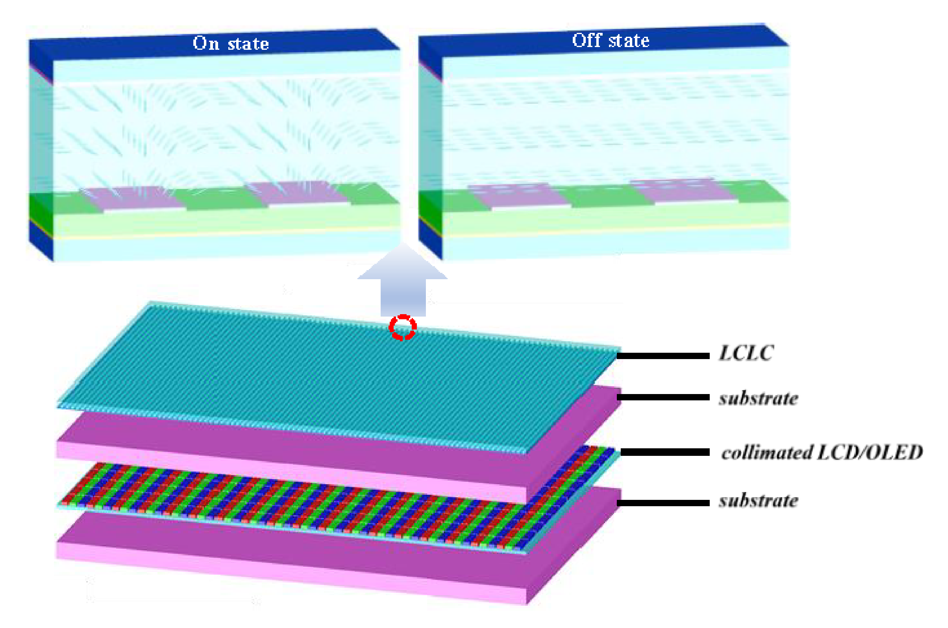
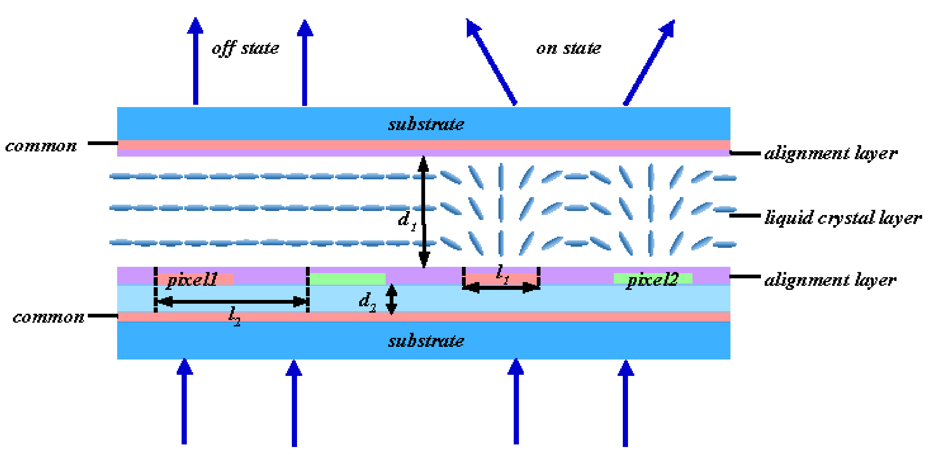
2. Device Structure and Principle

Figure 1 shows the schematic of a collimated LCD/OLED with the liquid crystal lens-like cell. The collimated LCD or OLED has a low color shift characteristic as a result of suppressing the phase difference of LC or blue shift of OLED. In the voltage off-state, the liquid crystal directors are uniformly distributed over the whole cell. The incident light from LCD or OLED is unchanged after transmitting the LCLC. When a voltage is applied to the LCLC, the liquid crystal directors are then rotated and a light-mixing layer is formed, the incident light from LCD or OLED can be tuned from a small viewing angle to a large viewing angle, and vice versa. When the incident light from a small off-axis angle is introduced, which accounts for the majority, owing to a collimated display, the incident light is diffused to a larger viewing angle on the whole. Therefore, the phase difference of LC layer and blue shift caused by the microcavity effect are reduced, and the color shift is decreased, while the brightness is increased at large viewing angles.
Figure 2 is the cross section view of the LCLC. A planer indium-tin-oxide (ITO) electrode is deposited on the bottom substrate, then a silicon dioxide layer is coated onto the common electrode. Above the silicon dioxide layer, two strips of pixel electrodes, made of ITO, are deposited. A planer alignment layer (such as polyimide, PI) is coated on pixel electrodes to align the liquid crystal molecules, the rubbing direction of alignment layer is perpendicular to the strip pixels. Meanwhile, the planer common electrodes and alignment layer are coated on the top substrate sequentially, with the rubbing alignment direction being the same as the bottom alignment layer. Finally, the liquid crystal layer is sandwiched between two substrates with electrodes and alignment layers. When the LCD or OLED is introduced, the LCLC is a uniform layer and has no effect on the incident light at the off-state. Owing to the rubbing direction of two alignment layers being the same, they are parallel to the polarization direction of the incident light from the displays and perpendicular to pixel one and pixel two. In the voltage on-state, a positive voltage is applied to pixel one while a negative voltage is applied to pixel two. Two common electrodes are introduced to increase the longitudinal electric field in the liquid crystal layer, and the applied voltages on two common electrodes are both set to 0 V. In Figure 2, the pixel electrode width l1 = 5 μm, the pixel electrode gap is 5 μm, the thickness of liquid crystal layer d1 = 10 μm, the thickness of SiO2 d2 = 1 μm, the thickness of common and pixel electrodes are both 0.1 μm, the top alignment layer is 0.1 μm, and the bottom alignment layer is 0.12 μm.
Figure 3 shows the electric field distribution in the LCLC of the voltage on-state. In Figure 3, the applied voltages for pixel one and pixel two are 8 V and −8 V, respectively. The longitudinal electric field emerges between the two strip pixel electrodes, and the transverse electric field is also produced above pixel one and pixel two concurrently. Then liquid crystal directors are reorientated by the electric field, as shown in Figure 3. The liquid crystal director is tilted to a larger angle, owing to the longitudinal electric field. By contrast, the tilt angles of the liquid crystal directors between the two pixels show a narrowing trend. As a linearly polarized light is parallel to the rubbing alignment direction, the effective refractive index can be expressed as:
n e f f = n e n o n o 2 sin 2 θ + n e 2 cos θ
where θ is the tilt angle of the liquid crystal director, and no and ne are the ordinary and extraordinary refractive index of liquid crystal, respectively. According to Equation (1), the effective refractive index of the liquid crystal above the pixels is lower than that between the pixels; high and low refractive index optical materials have a staggered arrangement in the liquid crystal layer. Thus, the liquid crystal turns into a nonuniform layer, and the incident light can be diffused.

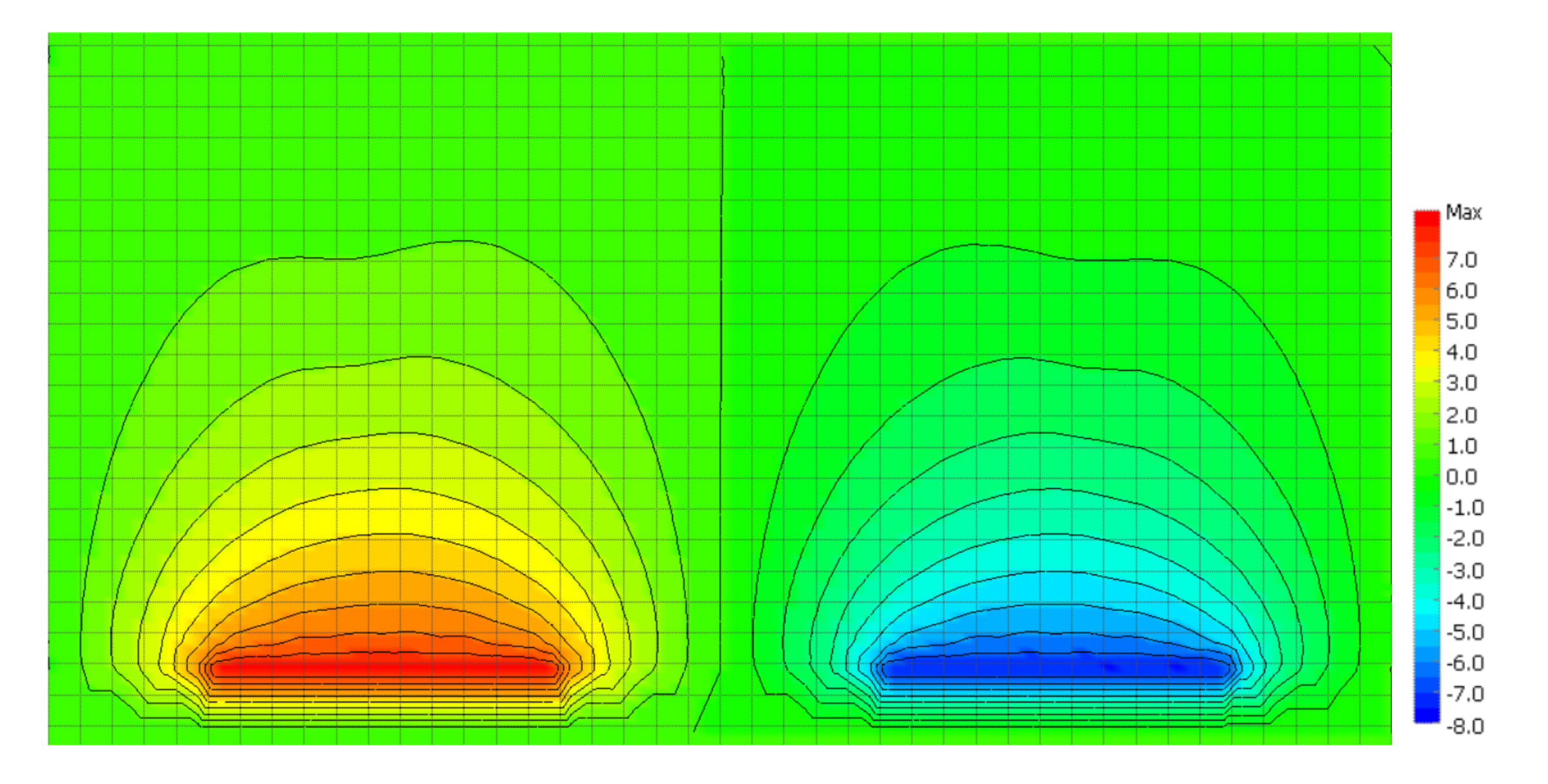
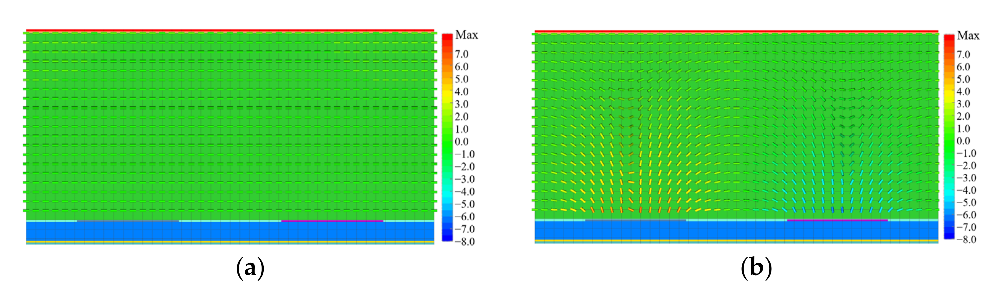
3. Simulation Results and Discussion

Simulations have been performed in order to validate and discuss the electro-optical properties of the proposed LCLC. The LC material used in our simulation was JC-TNLC-E7 (King Optronics Co. Ltd., Suzhou, China), its birefringence Δn is 0.224 (no is 1.517, ne is 1.741 @ λ = 550 nm), the viscosity γ1 = 29 mPas, and its dielectric anisotropy Δε = 11.4. The commercial software TechWiz LCD 3D (Sanayi System Co., Ltd., Incheon, Korea) was used to simulate the director distribution at different-applied voltages.
The effective refractive index neff of LCLC can be calculated according to the Equation (1) and the director distribution data, which is shown in Figure 4. Then, the accumulated phase retardation φ of the liquid crystal layer is calculated as:
φ = 2 π λ 0 d n e f f θ d z
where d is the thickness of the liquid crystal layer. When no voltage is applied on the LCLC, the liquid crystal directors are parallel to the substrates and show high uniformity, as shown in Figure 4a. As a result, the effective refractive index and the accumulated phase retardation are all the same, occupying different positions on the LCLC in the ideal condition. When the applied voltages on pixel one and pixel two are 8 V and −8 V, respectively, and the applied voltages on the two common electrodes are 0 V, a transverse electric field is produced in the middle of two pixels due to the electrical potential difference between these two electrodes. Therefore, the liquid crystal director is invariant, or the tilt angle of liquid crystal molecule is small in the corresponding position. Simultaneously, a strong longitudinal electric field predominates above the two pixels, and two common electrodes are introduced to increase the longitudinal electric field and its effective depth. Therefore, the tilt angle of the liquid crystal molecule is large in the corresponding position, as shown in Figure 4b.
When the applied voltage was conducted on the LCLC, the effective refractive index distribution in the cross-section was calculated as shown in Figure 5a. To a linearly polarized light, which the polarization direction is perpendicular to strip pixel electrodes, high and low refractive index optical materials have a staggered arrangement in the LCLC. The accumulated phase retardation difference (the difference of accumulated phase retardation and its minimum value) can be simulated by the effective refractive index distribution and calculated from Equation (2). The simulated result is shown in Figure 5b. The blue frame in Figure 5b shows a lens-like accumulated phase retardation distribution, obtained within the position of 7 to 13 μm in the x-axis. It can be seen that the curve of LCLC matches well with an ideal parabolic curve [31]. The incident light from different viewing angles can be mixed. It is worth mentioning that there are some director defects in the reminding positions; meanwhile, the effective refractive index and accumulated phase retardation are fluctuating. However, they also contribute to light mixing.
Based on MATLAB, the finite-difference time-domain (FDTD) method [32,33,34,35,36,37] was introduced to simulate the optical characteristics of the LCLC. Figure 6a shows the propagation process, when the voltage applied on both electrodes is zero. While passing through the LCLC with a vertical direction, the propagation direction of incident light is invariant, owing to the liquid crystal layer being a uniform medium. In our simulations, the wavelength of incident light is 550 nm. In the voltage on-state, the voltage applied on two pixel electrodes are 8 V and −8 V respectively, while the voltage on two common electrodes is 0 V. The light propagation process is shown in Figure 6b. The speed of light propagation above two pixel electrodes is relatively faster than that between two pixels, the incident light is curved, and the light-mixing effect is emerged.
In order to further research the light-mixing features of LCLC, the brightness distributions were also simulated in which the incident plane waves were propagated with different polar angles. The brightness distributions of Figure 6a,b are shown in Figure 7e. The red line indicates the voltage off-state; it can be seen that the peak of brightness distribution is at 0° and the brightness is sharply decreased when the viewing angle deviates from 0°. The black line in Figure 7 indicates the brightness distribution when the voltage is applied. As can be seen in Figure 7e, the incident light, which is propagated at a right angle to the substrate, can be diffused to a larger viewing angle; most of which are distributed within ±40° after the incident light passed through the LCLC, the light-mixing effects are obvious. Then, the polar angle of incident light is changed from −60° to 60° with steps of 15°. Figure 7a–i are the corresponding simulation results. It can be concluded from these Figures that the light-mixing effects are also intense when the incident angle varies. For example, the incident lights from different polar angles all contributed to increasing the brightness at a 0° viewing angle. As shown in Figure 7a–i, there is more contribution when the incident angles are 0° and ±30°, while the contributions are less when the incident angles are ±15, ±45, and ±60°. Based on the same principle, at a large viewing angle, the light injected into our eyes comes from larger and smaller polar angles, so the light-mixing effect is generated accordingly. However, the light from smaller viewing angles makes up the majority when a collimated display is induced. So, the brightness is increased at large viewing angles. Moreover, the color shift is decreased, owing to the light-mixing effect; a better viewing angle characteristic can be achieved when the voltage is applied on the LCLC. Furthermore, in the single wavelength collimated laser simulated in Figure 7, the diffraction and refraction effect are amplified heavily, as we can see a series of brightness peaks in Figure 7. However, in the actual display process, the light wave belongs to a multi band and divergent light source, so the phenomenon of multiple peaks or nonuniform light intensity will not occur to affect the display performance.
As shown is Figure 8, the distributions of incident light (collimated display) were measured by TCL China Star Optoelectronics Technology Co., Ltd., Shenzhen, China. The incident light is concentrated on the on axis direction and it is drastically reduced when the viewing angle is increased. The brightness loss is more than 50% when the viewing angles are 23° and 29° for OLED and LCD, respectively.
Then, the incident angle was tuned, and the process in Figure 7 was repeated 179 times for total polar angles (within the range from −89° to 89° with 1° step). The brightness distribution of incident light, which is shown in Figure 8, is taken into account. The brightness distribution of emergent light was simulated. When no voltage is applied on the LCLC, the liquid crystal layer is uniform, the emergent angles are almost the same as incident angles, and the brightness distribution are very similar, as shown in Figure 9a,c. It should be noted that the brightness distribution at large viewing angles (for example, more than 60°) are smaller than the data shown in Figure 8, due to the greater transmission loss of LCLC at large incident angles. When the voltage applied on two pixel electrodes is 8 V and −8 V respectively, and the applied voltage of two common electrodes is 0 V, a lens-like effective refractive index is generated and the light dispersion effect, such as refractive and diffractive phenomena, emerge in the liquid crystal layer. Figure 9b,d are the emergent light brightness distributions for the voltage on-state of OLED and LCD, respectively.
After the incident light of the display transmits the LCLC, a viewer could observe lights which are right in front of the screen. These observed lights come from different directions. In Figure 9b,d, the incident angles ranged from −35° to 35° for OLED, and 40° to 40° for LCD, which can be tuned to the 0° viewing angle by the LCLC. Moreover, when the incident angle from LCD or OLED is 0°, the range of its influence (polar angle range of emergent light) can achieve from −50° to 50°, as shown in Figure 7e and Figure 9b,d. The light-mixing effects are apparent in the voltage on-state.
Figure 10a,b shows the brightness distribution of the LCLC attached to the LCD or OLED at different applied voltages. When the applied voltage of the LCLC is 0 V, the brightness distribution is almost invariant, as seen in the dashed lines shown in Figure 10a,b. When compared with the voltage on-state, a high proportion of brightness decreases when the viewing angle is increased, and the brightness at small viewing angles is higher, as seen in the solid lines shown in Figure 10a,b. Moreover, the contrast loss at small viewing angles caused by diffusing and light-mixing effects is also avoided. The small viewing angle mode can be achieved by the voltage off-state of LCLC. When the applied voltage of the LCLC is 8 V, the brightness at small viewing angles is diffused to large viewing angles. Therefore, the brightness is appropriately reduced at small viewing angles, while the brightness at large viewing angles is notably enhanced. For example, the brightness loss at a 0° viewing angle is 19% and 29% for OLED and LCD, respectively, which increased by 84% for OLED and 64% for LCD at 45° viewing angles. The color shift at different viewing angles is limited because of the light-mixing effect. When the voltage is applied on the LCLC, a high brightness and low color shift display at large viewing angles can be acquired.

4. Conclusions

A collimated display is introduced to avoid the blue shift of OLED and the phase difference of LCD, and the color shift can be significantly reduced. However, bad viewing angle performance usually exists when using the collimated display. So, the LCLC is proposed to eliminate this negative influence to a great extent. Using the LCLC, a low color shift and brightness-enhanced display was developed and the following principle of the light-mixing effect was also investigated. The improved display can switch from a wide viewing angle mode to narrow viewing angle mode by applied voltage. Moreover, the simulation results of the light diffusion and brightness increasement of LCD and OLED demonstrate the success of the proposed technique.

Author Contributions

H.D. and L.W. conceived the original idea and wrote the paper; G.R. and Y.-Q.D. helped perform the analysis with constructive discussions. X.-T.Z., J.-Y.O., J.-Y.Y. and Y.-T.Z. analyzed the data. All authors have read and agreed to the published version of the manuscript.

Funding

The work is supported by the fellowship of China Postdoctoral Science Foundation under Grant No. 2020M680227, and the Science Foundation of Civil Aviation Flight University of China under Grant Nos. J2021-054 and JG2019-19.

Institutional Review Board Statement

Not applicable.

Informed Consent Statement

Not applicable.

Data Availability Statement

Not applicable.

Acknowledgments

We are grateful for the support from TCL China Star Optoelectronics Technology Co., Ltd.

Conflicts of Interest

The authors declare no conflict of interest.

References

  1. Huang, Y.; Hsiang, E.L.; Deng, M.Y.; Wu, S.T. Mini-LED, Micro-LED and OLED displays: Present status and future perspectives. Light Sci. Appl. 2020, 9, 105. [Google Scholar] [CrossRef] [PubMed]
  2. Chen, H.W.; Lee, J.H.; Lin, B.Y.; Chen, S.; Wu, S.T. Liquid crystal display and organic light-emitting diode display: Present status and future perspectives. Light Sci. Appl. 2018, 7, 17168. [Google Scholar] [CrossRef]
  3. Bae, K.S.; Oh, M.; Park, B.; Cho, Y.J.; Kim, D. 51-1 Novel Pixel Structure for 8K QUHD LCD Panel with the Enhanced Optical Performances. SID Symp. Dig. Tech. Pap. 2019, 50, 703–706. [Google Scholar] [CrossRef]
  4. Oke, R.; Maruyama, J.; Murakoso, T.; Ishii, M.; Hiyama, I.; Kato, Y.; Yamashita, H.; Tanioka, K.; Chiba, T. 55-in. 8K4K IPS-LCDs with wide viewing angle, high frame frequency, wide color gamut, and stereoscopic. Opt. Eng. 2018, 57, 075102. [Google Scholar] [CrossRef] [Green Version]
  5. Sato, M.; Kurosaki, D.; Nakazawa, Y.; Okazak, I.K.; Oezuka, J. 42-2: Low Power Consumption 8K Liquid Crystal Display with Oxide Semiconductor/Oxide Conductor Pixel (Transparent Pixel). SID Symp. Dig. Tech. Pap. 2017, 48, 596–599. [Google Scholar] [CrossRef]
  6. Terashita, S.; Watanabe, K.; Shimoshikiryoh, F. 6-2: Novel Liquid Crystal Display Mode “UV2A II” with Photo Alignment Technology for a Large-Screen 8K Display. SID Symp. Dig. Tech. Pap. 2019, 50, 62–65. [Google Scholar] [CrossRef]
  7. Dou, H.; Chen, M.; Li, D.; Yu, G.; Sun, Y.B. A controllable viewing angle optical film using micro prisms filled with liquid crystal. Liq. Cryst. 2021, 48, 1373–1381. [Google Scholar] [CrossRef]
  8. Lu, R.; Wu, S.T.; Lee, S.H. Reducing the color shift of a multidomain vertical alignment liquid crystal display using dual threshold voltages. Appl. Phys. Lett. 2008, 92, 051114. [Google Scholar] [CrossRef] [Green Version]
  9. Lu, R.; Qi, H.; Ge, Z.; Wu, S.T. Color shift reduction of a multi-domain IPS-LCD using RGB-LED backlight. Opt. Express 2006, 14, 6243–6252. [Google Scholar] [CrossRef]
  10. Schadt, M.; Seiberle, H.; Schuster, A. Optical patterning of multi-domain liquid-crystal displays with wide viewing angles. Nature 1996, 381, 212–215. [Google Scholar] [CrossRef]
  11. Park, J.H.; Oh, S.W.; Huh, J.W.; Yoon, T.H. Four-domain electrode structure for wide viewing angle in a fringe-field-switching liquid crystal display. J. Disp. Technol. 2016, 12, 667–672. [Google Scholar] [CrossRef]
  12. Guo, Y.Q.; Li, X.S.; Sun, Y.; Zhang, C.; Yang, Y.L.; Zhang, H.; Ma, H.M.; Sun, Y.B. Low gamma shift blue-phase liquid crystal display with electric filed induced multi-domain electrode structure. Liq. Cryst. 2020, 47, 54–66. [Google Scholar] [CrossRef]
  13. Oh, S.W.; Yoon, T.H. Achromatic wide-view circular polarizers for a high-transmittance vertically-aligned liquid crystal cell. Opt. Lett. 2014, 39, 4683–4686. [Google Scholar] [CrossRef] [PubMed]
  14. Mori, H. The Wide View (WV) Film for Enhancing the Field of View of LCDs. J. Disp. Technol. 2005, 1, 179–186. [Google Scholar] [CrossRef]
  15. Mori, H.; Itoh, Y.; Nishiura, Y.; Nakamura, T.; Shinagawa, Y. Performance of a Novel Optical Compensation Film Based on Negative Birefringence of Discotic Compound for Wide-Viewing-Angle Twisted-Nematic Liquid-Crystal Displays. Jpn. J. Appl. Phys. 1997, 36, 143–147. [Google Scholar] [CrossRef]
  16. Saitoh, Y.; Kimura, S.; Kusafuka, K.; Shimizu, H. Optimum Film Compensation of Viewing Angle of Contrast in In-Plane-Switching-Mode Liquid Crystal Display. Jpn. J. Appl. Phys. 1998, 37, 4822–4828. [Google Scholar] [CrossRef]
  17. Oh, S.W.; Yoon, T.H. Elimination of light leakage over the entire viewing cone in a homogeneously-aligned liquid crystal cell. Opt. Express 2014, 22, 5808–5817. [Google Scholar] [CrossRef] [PubMed]
  18. Oikawa, T.; Yasuda, S.; Takeuchi, K.; Sakai, E.; Mori, H. Novel WV film for wide-viewing-angle TN-mode LCDs. J. Soc. Inf. Disp. 2012, 15, 133–137. [Google Scholar] [CrossRef]
  19. Guo, Y.; Li, X.; Yang, Y.; Zhang, C.; Sun, Y.; Zhang, H.; Sun, Y. Low-gamma shift asymmetrical double-side blue-phase liquid crystal display. Liq. Cryst. 2020, 47, 199–210. [Google Scholar] [CrossRef]
  20. Liu, Y.; Lan, Y.F.; Hong, Q.; Wu, S.T. Compensation Film Designs for High Contrast Wide-View Blue Phase Liquid Crystal Displays. J. Disp. Technol. 2013, 10, 3–6. [Google Scholar] [CrossRef]
  21. Park, S.S.; Sohn, I.; Cho, E.; Park, S.; Kim, E. Color Shift Reduction of Liquid Crystal Displays by Controlling Light Distribution Using a Micro-Lens Array Film. J. Disp. Technol. 2012, 8, 643–649. [Google Scholar] [CrossRef]
  22. Park, M.K.; Park, H.; Joo, K.I.; Jeong, H.D.; Kim, H.R. Continuous Viewing Angle Distribution Control of Liquid Crystal Displays Using Polarization-Dependent Prism Array Film Stacked on Directional Backlight Unit. J. Opt. Soc. Korea 2016, 20, 799–806. [Google Scholar] [CrossRef] [Green Version]
  23. Chen, H.W.; Zhu, R.D.; He, J.; Duan, W.; Hu, W.; Lu, Y.Q.; Li, M.C.; Lee, S.L.; Dong, Y.J.; Wu, S.T. Going beyond the limit of an LCD’s color gamut. Light Sci. Appl. 2017, 6, e17043. [Google Scholar] [CrossRef] [PubMed] [Green Version]
  24. Tan, G.; Lee, J.H.; Lin, S.C.; Zhu, R.; Wu, S.T. Analysis and optimization on the angular color shift of RGB OLED displays. Opt. Express 2017, 25, 33629. [Google Scholar] [CrossRef]
  25. Park, W.Y.; Kwon, Y.; Lee, C.; Whang, K.W. Light outcoupling enhancement from top-emitting organic light-emitting diodes made on a nano-sized stochastic texture surface. Opt. Express 2014, 22, A1687. [Google Scholar] [CrossRef]
  26. Park, W.Y.; Kwon, Y.; Cheong, H.W.; Lee, C.; Whang, K.W. Increased light extraction efficiency from top-emitting organic light-emitting diodes employing a mask-free plasma-etched stochastic polymer surface. J. Appl. Phys. 2016, 119, 095502. [Google Scholar] [CrossRef]
  27. Gu, X.; Qiu, T.; Zhang, W.; Chu, P.K. Light-emitting diodes enhanced by localized surface plasmon resonance. Nanoscale Res. Lett. 2011, 6, 199. [Google Scholar] [CrossRef] [Green Version]
  28. Jung, M.; Yoon, D.M.; Kim, M.; Kim, C.; Lee, T.; Kim, J.H.; Lee, S.; Lim, S.H.; Woo, D. Enhancement of hole injection and electroluminescence by ordered Ag nanodot array on indium tin oxide anode in organic light emitting diode. Appl. Phys. Lett. 2014, 105, 013306. [Google Scholar] [CrossRef]
  29. Song, H.J.; Han, J.; Lee, G.; Sohn, J.; Kwon, Y.; Choi, M.; Lee, C. Enhanced light out-coupling in OLED employing thermal-assisted, self-aggregated silver nano particles. Org. Electron. 2018, 52, 230. [Google Scholar] [CrossRef]
  30. Chan, Y.P.; Choi, B. Enhanced Light Extraction from Bottom Emission OLEDs by High Refractive Index Nanoparticle Scattering Layer. Nanomater. Basel 2019, 9, 1241. [Google Scholar]
  31. Dou, H.; Chu, F.; Guo, Y.Q.; Tian, L.L.; Wang, Q.H.; Sun, Y.B. Large aperture liquid crystal lens array using a composited alignment layer. Opt. Express 2018, 26, 9254–9262. [Google Scholar] [CrossRef] [PubMed]
  32. Kriezis, E.E.; Elston, S.J. Finite-difference time domain method for light wave propagation within liquid crystal devices. Opt. Commun. 1999, 165, 99–105. [Google Scholar] [CrossRef]
  33. Kriezis, E.E.; Elston, S.J. Light wave propagation in liquid crystal displays by the 2-D finite-difference time-domain method. Opt. Commun. 2000, 177, 69–77. [Google Scholar] [CrossRef]
  34. Hwang, D.K.; Rey, A.D. Computational modeling of the propagation of light through liquid crystals containing twist disclinations based on the finite-difference time-domain method. Appl. Opt. 2005, 44, 4513. [Google Scholar] [CrossRef] [PubMed]
  35. Prokopidis, K.P.; Zografopoulos, D.C.; Kriezis, E.E. Rigorous broadband investigation of liquid-crystal plasmonic structures using finite-difference time-domain dispersive-anisotropic models. J. Opt. Soc. Am. B 2013, 30, 2722–2730. [Google Scholar] [CrossRef]
  36. Ogawa, Y.; Fukuda, J.I.; Yoshida, H.; Ozaki, M. Finite-difference time-domain analysis of cholesteric blue phase II using the Landau–de Gennes tensor order parameter model. Opt. Lett. 2013, 38, 3380–3383. [Google Scholar] [CrossRef]
  37. Dou, H.; Ma, H.M.; Sun, Y.B. Optical simulation of in-plane-switching blue phase liquid crystal display using the finite-difference time-domain method. Chin. Phys. B 2016, 25, 117–121. [Google Scholar] [CrossRef]
Figure 1. The schematic of a collimated LCD/OLED with the liquid crystal lens-like cell.
Crystals 12 00213 g001
Figure 2. The cross section view of the liquid crystal lens-like cell.
Crystals 12 00213 g002
Figure 3. The electric field distribution of the LCLC on voltage on-state.
Crystals 12 00213 g003
Figure 4. Liquid crystal director distribution in the cross section of the LCLC in the voltage off-state (a) and voltage on-state (b).
Crystals 12 00213 g004
Figure 5. Effective refractive index distribution in the cross-section (a) and the accumulated phase retardation (b) of the LCLC.
Crystals 12 00213 g005aCrystals 12 00213 g005b
Figure 6. A short vertical incident light propagated through the LCLC at different time moments: (a) the applied voltage on electrodes was 0 V; (b) the applied voltage on two pixel electrodes were ±8 V and the applied voltage on two common electrodes was 0 V.
Crystals 12 00213 g006aCrystals 12 00213 g006b
Figure 7. The brightness distribution when the polar angle of incident light is different: (a) −60°; (b) −45°; (c) −30°; (d) −15°; (e) 0°; (f) 15°; (g) 30°; (h) 45°; (i) 60°.
Crystals 12 00213 g007
Figure 8. The brightness distribution of LCD and OLED.
Crystals 12 00213 g008
Figure 9. The emergent light brightness distribution with different incident angles of OLED: (a) for voltage off-state of OLED; (b) for voltage on-state of OLED; (c) for voltage off-state of LCD; (d) for voltage on-state of LCD.
Crystals 12 00213 g009
Figure 10. The brightness distribution at different applied voltages: (a) the LCLC is attached to LCD; (b) the LCLC is attached to OLED.
Crystals 12 00213 g010
Publisher’s Note: MDPI stays neutral with regard to jurisdictional claims in published maps and institutional affiliations.

