Article

Control of Welding Speed and Current in Machine–Human Cooperative Welding Processes

1
Beijing Spacecrafts Co., Ltd., Beijing 100094, China
2
Faculty of Materials and Manufacturing, Beijing University of Technology, Beijing 100124, China
*
Author to whom correspondence should be addressed.
Crystals 2022, 12(2), 235; https://doi.org/10.3390/cryst12020235
Submission received: 29 December 2021 / Revised: 30 January 2022 / Accepted: 6 February 2022 / Published: 9 February 2022
(This article belongs to the Special Issue Investigation on the Formation and Properties of Steels)

Abstract

:
In intelligent manufacturing processes, the dependence of the weld quality on the welder’s skills in manual welding should be minimized. To better control the welding quality, a machine–human cooperative control system was designed in this study, and a skills learning experiment was conducted to correlate the relationship between welding speed and welding current. The obtained skills were then transferred to the control system to control the human welder to achieve the desired welding speed. In addition, to adjust the welding current to control the welding power, the desired full penetration welds were finally obtained. In the present study, full penetration welds with different welding speeds were obtained in a 304 stainless steel pipe having a wall thickness of 2.03 mm and an outside diameter of 113.5 mm using the machine–human cooperative welding process. The back fusion width was 2.3 to 5.5 mm, which met the quality requirements of the weld. This study provides a research direction for effectively solving the problem of the shortage of welders and for helping unskilled welders to produce quality welds, and lays the foundation for developing the next generation of machine–human cooperative intelligent welding system.

Graphical Abstract

1. Introduction

Welding technology is one of the important processes of machinery manufacturing, and is widely used in aerospace, rail transportation, petrochemical, and other industrial fields [1,2,3]. Manual welding will continue to play an irreplaceable role, but there are also urgent problems that need to be solved [4,5,6]. One of the most important problems is that the quality of manual welding depends on the welder’s operating skills and the field response, and the shortage of skilled human welders highlights this problem [7,8,9].
With the rapid development of information technology, intelligent welding technology based on information technology has become a popular research topic in the industrial community. Within this, automatic welding is developing rapidly. Reliable control in the welding process is needed for the purpose to achieving low cost and high productivity. Recently, a large number of sensing methods have been used, such as radiography-based control [10], oscillation-based control [11,12], vision-based control [13,14,15], and thermal-based control [16,17], to control and improve the weld quality. In this field, pioneering work on the observation of the weld pool was conducted by Rokhlin et al. [18], using radiography. Zhang [19] proposed a novel mechanism for observing the GTA weld pool surface shape by eliminating the influence of the bright arc light. These methods help us to deeply understand and control the welding process.
Despite the trend of growing automation in industrial processes and machines, the human operator/controller is still irreplaceable in various applications [20,21,22]. The problem of the shortage of senior welders can be alleviated to a certain extent by mixing the human sensory information (via visual, auditory, and tactile sensing methods during the real welding process) and empirical knowledge (molten pool, arc sound, and weld appearance) with traditional mechanized and automated welding [23,24]. Specifically in welding operations, a welder makes decisions primarily based on past learned experiences/skills, which may not involve a fundamental understanding of the laws of welding physics. Moreover, a human welder assesses and controls a welding process using a humanistic approach where the feedback sensory information acquired by the welder may be imprecise and only reflects partial truths about the instant status of the weld process.
The integration of welders’ reasoning and judgment capabilities with machines is a fundamental requirement to help less-experienced welders produce quality welds, i.e., giving machines a “human (skilled welder’s) brain” [25,26,27]. In the field of welding fabrication, Zhang et al. at the University of Kentucky [8,9] established a model of skilled welders’ behavior to estimate weld penetration and adjust the welding current based on the real-time 3D spatial shape of the molten pool. The experiment was conducted by measuring the weld pool surfaces (point set) by the laser reflection imaging method given different velocity signals during the welding process, and then identifying the relationship model between the current adjustment value and the 3D information of the weld pool surface by the least squares method. Liu et al. [20,21,22] at the University of Kentucky reproduced the weld pool and welding surroundings in the robot welding process in the laboratory through virtualization, and the welders adjusted their arm movement and welding current by observing the weld pool and welding surroundings after virtualization. The laboratory motion and data detection system detected welders’ arm movements and welding current adjustment values, and sent them to the welding robot for execution at the welding site. Excellent results were achieved. Subsequently, Huang et al. [23,24] welded 304 stainless steel pipe using a machine–human cooperative GTAW welding platform based on auditory commands. The analysis of the test results showed that the designed interval model controller achieved good control effects. The main factor affecting the weld penetration was the heat input, which is mainly determined by the welding speed and welding current. However, the current regulation was not controlled accordingly in the above test.
The problem of welding speed fluctuations during manual GTAW welding by human welders can be readily solved if the welding current value can be adjusted accordingly in a machine–human cooperative welding system [28,29,30,31,32,33]. In this paper, the designed machine–human cooperative system was refined and verified in real welding. The first step is learning the operating experience of skilled human welders—that is, the empirical skills of skilled welders in adjusting the welding speed through different welding current conditions—and extracting the relationship model between the two. Subsequently, the learned empirical skills are fused with a previously designed machine–human cooperative control system to constitute an intelligent controller for welding speed control and current compensation; on the one hand, the actual speed of the human welder is monitored to correct the speed deviation, and on the other hand, based on the empirical model of welding current and welding speed, the welding current value is reasonably matched according to the real-time welding speed to minimize the impact of the human welder’s operational errors. Finally, the feasibility of this design was verified by carrying out machine–human cooperative GTAW welding to obtain a full penetration weld, and a detailed analysis of the welding results was performed to evaluate the control quality of the machine–human cooperative system.

2. Methods

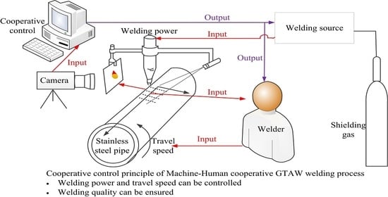
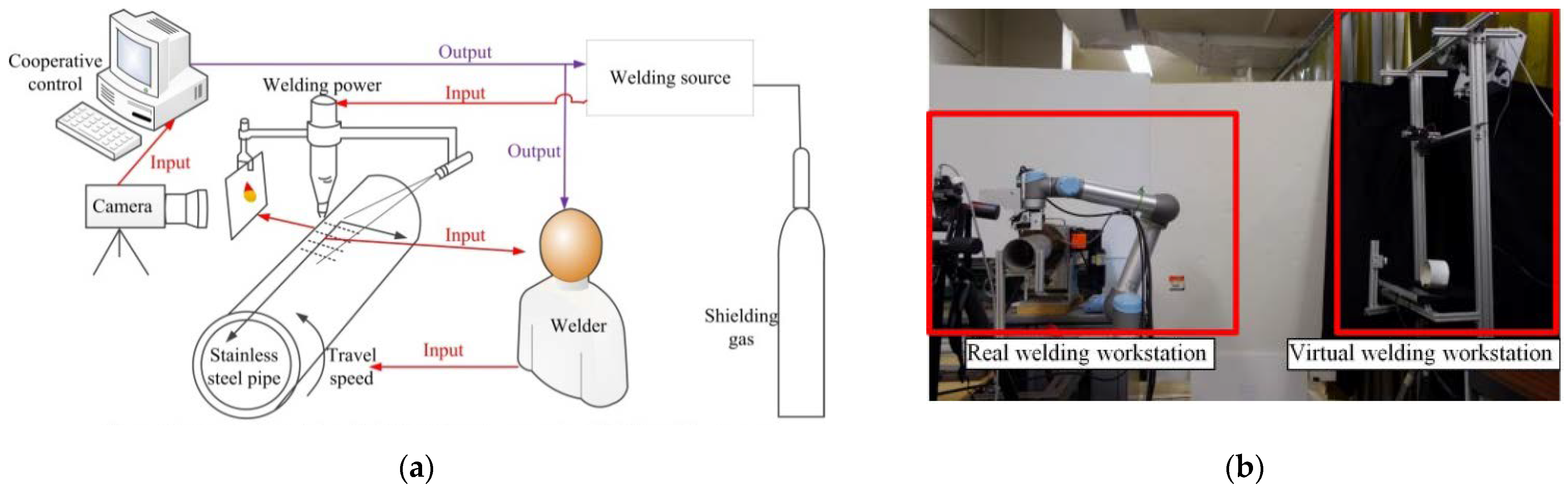
2.1. Experimental System

The virtual reality welding system in Figure 1 consists of two main parts, both of which exchange and transmit data via Ethernet. In the welding process, the molten pool image is taken by the camera, which is then projected to the virtual scene. One part is the reality welding system, a six degrees of freedom UR-5 industrial robot arm (the UR-5 industrial robot is a six-jointed robot arm with a low weight of 18 kilos, lifting ability of 5 kilos, and working radius of 85 cm; the accuracy of the robot’s repetitions is 0.1 mm) with a GTAW welding torch (the welding machine is a Miller Dynasty 400) and a camera at the end of its arm, which is mainly used to carry out the actual welding task and observe the molten pool in real time through the camera. The other part is the virtual welding system, which projects the molten pool information captured by the camera onto the virtual workpiece in real time through a projector, and the skilled human welder adjusts the running speed of the virtual welding torch based on the molten pool information, while sensors monitor the movement of the torch and convert the data into robot language through the controller to control the robot arm movement. The sensor monitor is a leap sensor, which is an important part of the welding speed monitoring system. The leap sensor is an advanced motion sensor that accurately captures the welding torch position and calculates the welding speed. The sensor can observe a roughly hemispherical area to a distance of about 1 m. It can track fingers or similar items to a spatial precision of 0.01 mm. The leap sensor measures at 60 Hz, which is much faster than the sample rate of the system (10 Hz) and the human response speed [15,16,17].

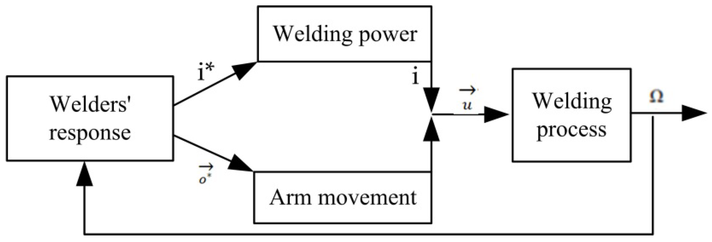
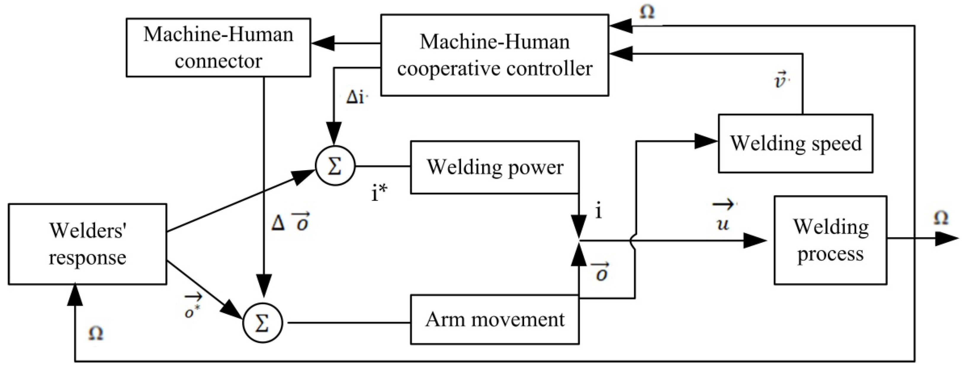
2.2. Principle of Experiment

Figure 2 is a block diagram of a system for online real-time adjustment of welding parameters by a skilled welder. It shows the welding process, the welding power supply, the arm movement of the welder, and the human welder (the welder’s response). The welding process described here is a manual GTAW welding process operated by the human welder; in addition, this block diagram can also be represented as an automatic welding process operated by the welder who only applies different means to adjust the welding parameters. Therefore, the welding process shown in Figure 2 is defined as a manual welding process.
In manual GTAW welding, the welder moves the torch along the weld seam, describing the GTAW arc as a vector, as shown in Equation (1).
u = ( i , o )
where i is the welding current value; o represents all welding variables generated by the welder’s arm movement. Among these, o signifies welding parameters such as welding speed, arc height, and torch attitude. The welder adjusts the welding parameters of the current value and the arm action to adjust the welding variables by observing the weld area (mainly the molten pool surface) and after judging through his own experience, which, in this study, was simplified to welding speed. The human welder adjusts the welding current and welding speed according to the molten pool and other information collected from the controller during the welding process. Therefore, the design of the intelligent controller is used as a reference to maximize the replacement of the welder’s sensing, judgment, and decision-making process, thus removing the dependence of the welder on experience and skills. The schematic diagram of the real-time dynamic adjustment of the welder’s actions and welding current to assist the welder in the welding process is shown in Figure 3.

2.3. Experimental Process and Parameters

To ensure the authenticity of skilled welders in the virtual welding platform, the size of the selected workpiece model was the same as the size of the 304 stainless steel pipe. The molten pool images captured by the camera are projected on the workpiece model in real time and intuitively through the projector, and the position of the projector and the workpiece model is calibrated. The position of the molten pool images projected onto the workpiece model is synchronized with the real pipe, that is, the molten pool images fall just below the virtual welding torch. Figure 4a is a realistic picture of the welded workpiece as seen by the naked eye and Figure 4b is a virtual visual image projected onto the workpiece model through the projector. The welding torch is at the 12 o’clock position of the pipe, and the image projected onto the workpiece model is also at the 12 o’clock position, thus maximizing the restoration of the real welding state. The next section presents the results of welding tests at different current values completed by skilled welders using virtual reality welding.
The welding power supply is a constant current source with positive DC in order to obtain the relationship between the welding current and the welding speed under a full penetration weld. In order to obtain the empirical equation, 9 groups of welding tests with different welding currents were designed. The welded workpiece was 304 stainless steel pipe with a wall thickness of 2.03 mm and an outside diameter of 113.5 mm, and the welding position was selected to be between the 11 o’clock and 1 o’clock positions with low welding difficulty; the specific parameters are shown in Table 1. In order to verify the control quality of the control system, 5 groups of tests were designed, and the specific welding parameters are shown in Table 2; the welding speeds were 0.8, 1.0, and 1.2 mm/s. The welder’s operational skills are required to be higher for the welding speed of 0.8 mm/s; thus, three groups of repeatability tests were needed. Therefore, the first 3 groups were set as 0.8 mm/s, and the fourth and fifth groups were set as 1.0 and 1.2 mm/s, respectively. The initial welding current values were set to 48, 50, and 52 A. Argon was passed into the pipe as back protection to prevent oxidation. At the same time, the welding current and welding voltage signals were recorded in real time during the welding process to facilitate analysis of the results.

3. Experimental Results and Analysis

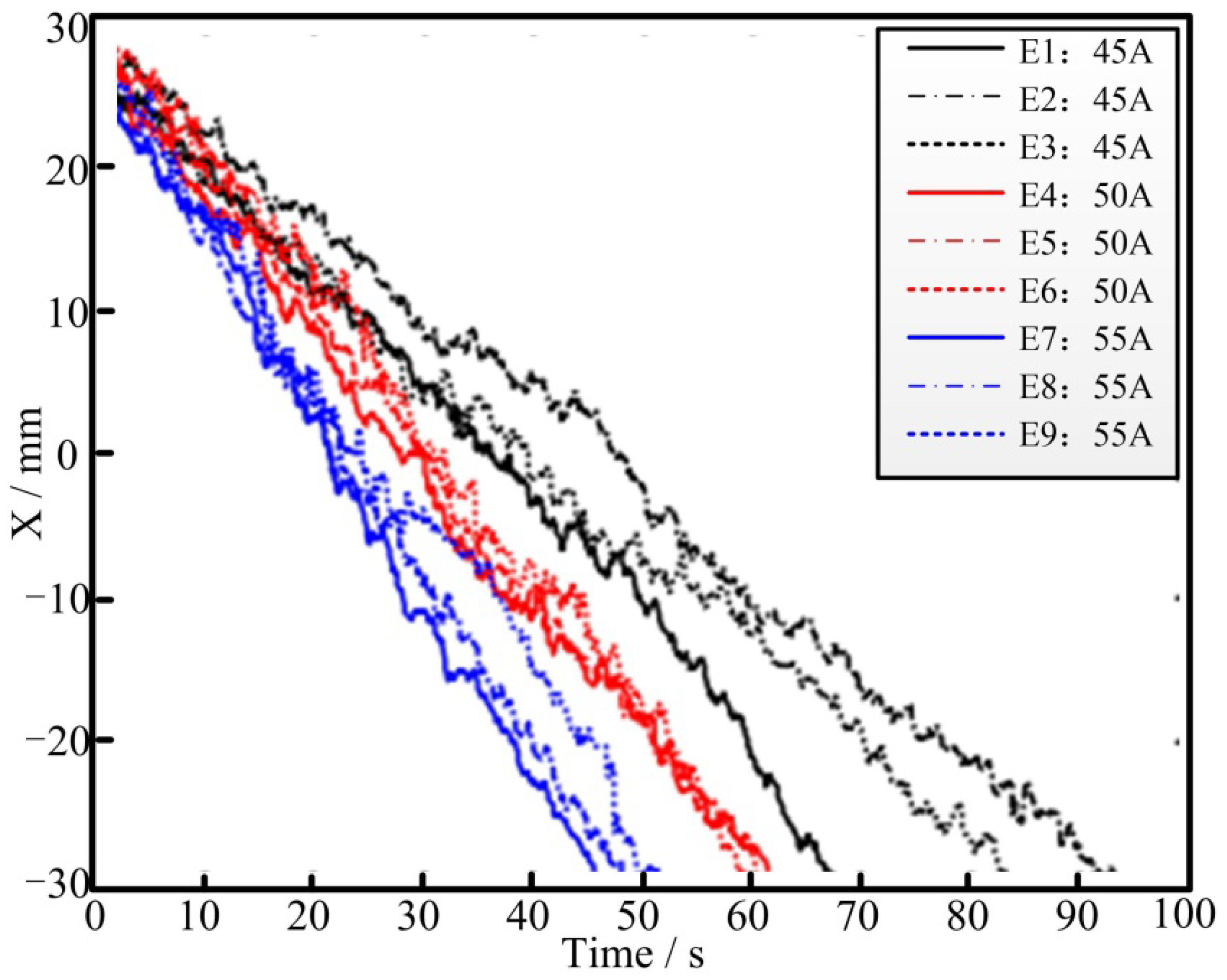
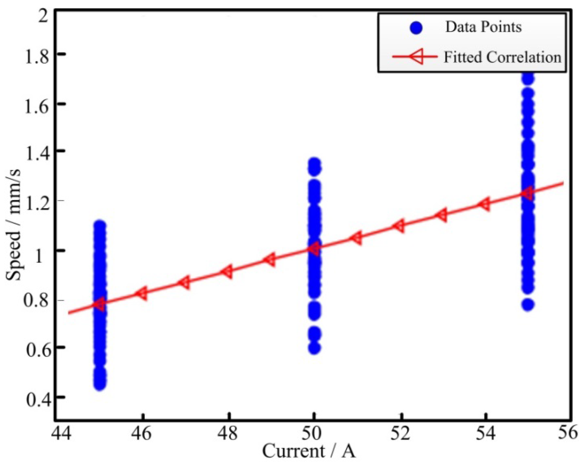
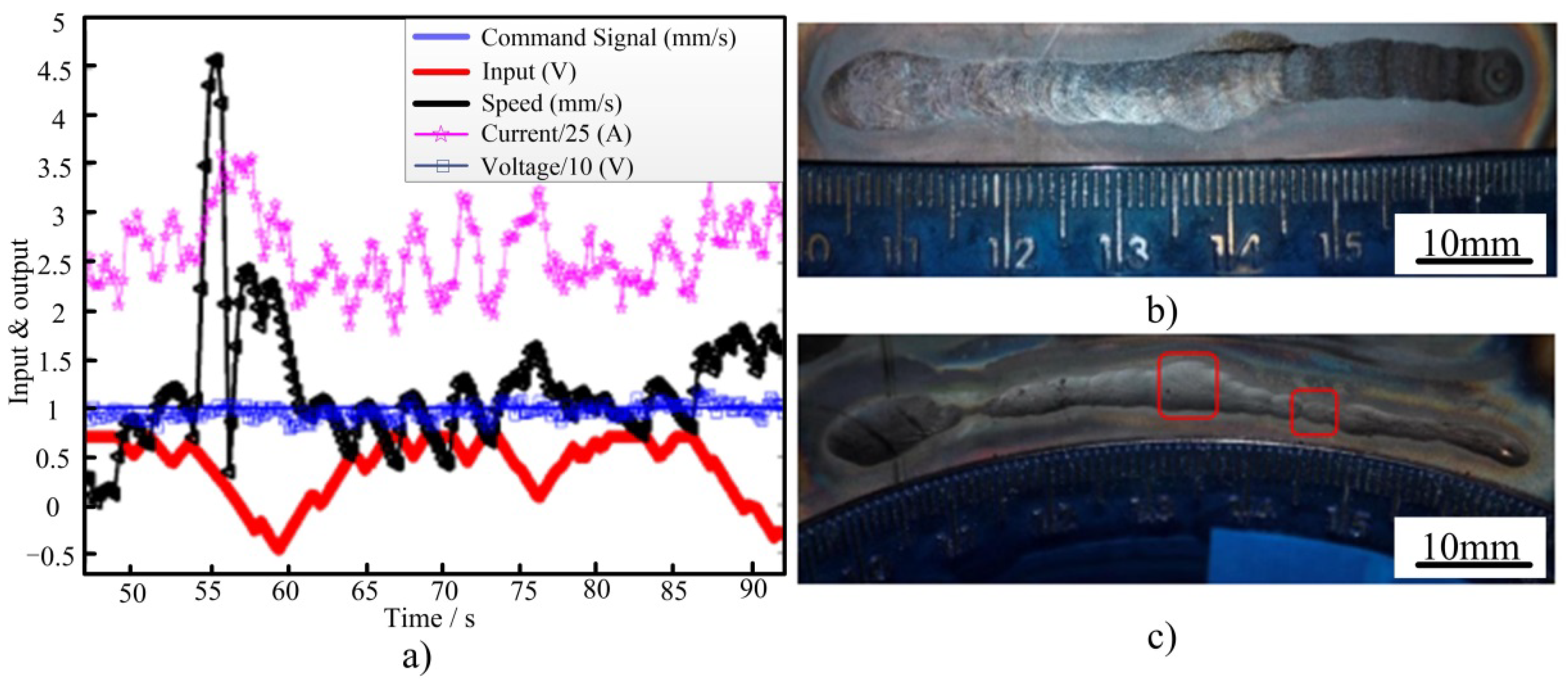
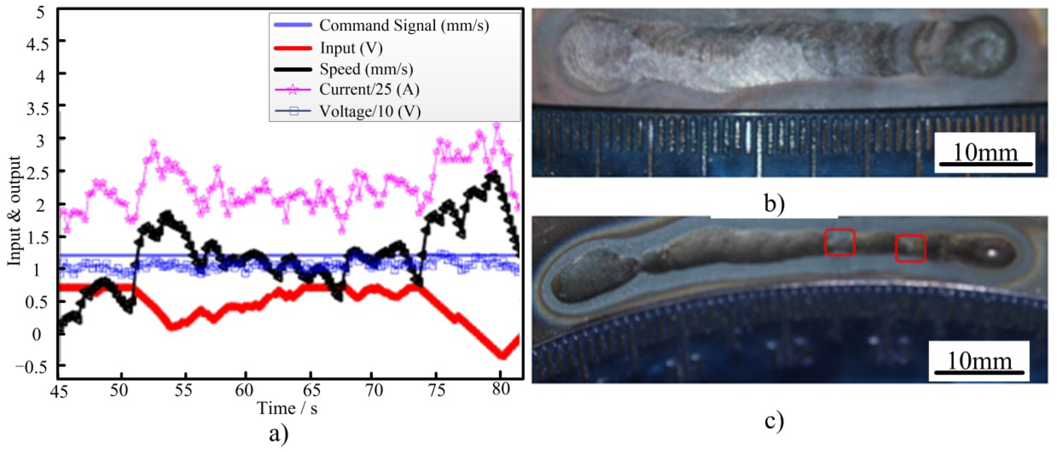
3.1. Relationship between Welding Rate and Current

Figure 5 shows the projection of the molten pool on the workpiece model at different current values selected randomly, where Figure 5a–c shows the welding current values of 55, 50, and 45 A, as listed in Table 1. These group tests were used to obtain the empirical equation. As can be observed from the figure, the shape of the molten pool is obviously different with different welding currents and welding speeds. Therefore, the human welder can observe the virtual molten pool to determine the weld penetration and adjust their welding speed accordingly.
Tests with different welding current values were carried out in order to obtain skilled welders’ welding experience. Different speed curve results are shown in Figure 6; the welding current of test groups 1–3 was 45 A, that of test groups 4–6 was 50 A, and that of test groups 7–9 was 55 A. The Y-axis in Figure 6 shows the distance of the weld, the value of 0 mm is at the 12 o’clock position, and −30 and 30 are the distances to the 12 o’clock position. The workpiece material is generally known, so the heat input to ensure its penetration is certain. Therefore, the speed of the torch increases accordingly (it takes less time to weld the same length, about 45 to 50 s, as shown in Figure 6, with a large welding current value (55 A)). The welder completes the virtual welding test at a medium welding speed of about 60 s at a medium current value (50 A). Moreover, the welding speed is reduced accordingly with a low welding current value (45 A), in which case it takes about 70 to 90 s to complete the welding. The discrepancy in the tests of 45 A was much more evident. There are two reasons for the larger discrepancy. The first is the initial temperature, because all of the tests were conducted on the same pipe and the current of the first test group was 45 A. The second is the different penetration, because the welding speed is fast when the back of the welding line is small. In each group of tests, the time required to complete the welding varies with the same welding current value because the welder needs to ensure the weld penetration, which is determined by the molten pool during the welding process, and then adjusts the welding speed in real time.
From the obtained welding speed data, the relationship between the welding speed and the welding current value was determined and analyzed. As can be seen in Figure 6, significant high-frequency noise exists in the welder’s arm movement profile, so a filter was first designed to process the raw data. The designed low-pass filter is shown in Equation (2).
{ D x f , k = a D x f , k 1 + ( 1 a ) D x , k S x f , k = ( D x f , k D x f , k 1 ) / T s
where Dx is the X-axis coordinate before filtering, Dxf is the X-axis coordinate after filtering, Sxf is the welding speed in the X-axis direction after filtering, Ts is the sampling time (0.5 s), and a(0,1) is the filter coefficient. An increase in the filter coefficient a increases the deviation of the X-axis position from the actual arm movement of the welder, but also increases the robustness and roundness of the curve. A value of a = 0.9 can effectively eliminate noise and ensure a truth value.
The welding torch is always perpendicular to the tangential direction of the stainless steel pipe fittings during the welding process, that is, the angle b between the welding torch and the direction of gravity is about −25 to 25 degrees (from approximately the 11 o’clock position to the 1 o’clock position). As the welding position is located in the upper part of the pipe, the tilt of the welding torch has little impact on the weld penetration, and the welding speed obtained from each group of tests is around the average speed fluctuations of varying degrees. Thus, no significant effect of torch tilt on the welding speed was found.
The obtained welding speed data were used in linear fitting to obtain a relationship model between the welding current and the welding speed, and the results are shown in Figure 7. The data shown in Figure 7 have a wide dispersion, but the speed value used for the linear regression was the average value of each welding current. The least square data fitting was used to obtain the linear model [23], as shown in Equation (3).
s = 0.0462 I 1.3
The relationship model between welding current and welding speed was applied to the machine–human cooperative welding system proposed in this paper; specifically, the primary welder holds the torch (monitoring their actual arm movement) and the intelligent controller guides the welder to fine-tune the welding speed through visual commands. At the same time, combined with the above welder’s experience, the welding current is adjusted in real time by the welding power supply to compensate for the insufficient or excessive heat input caused by welding speed deviation and to obtain an ideal full penetration weld.

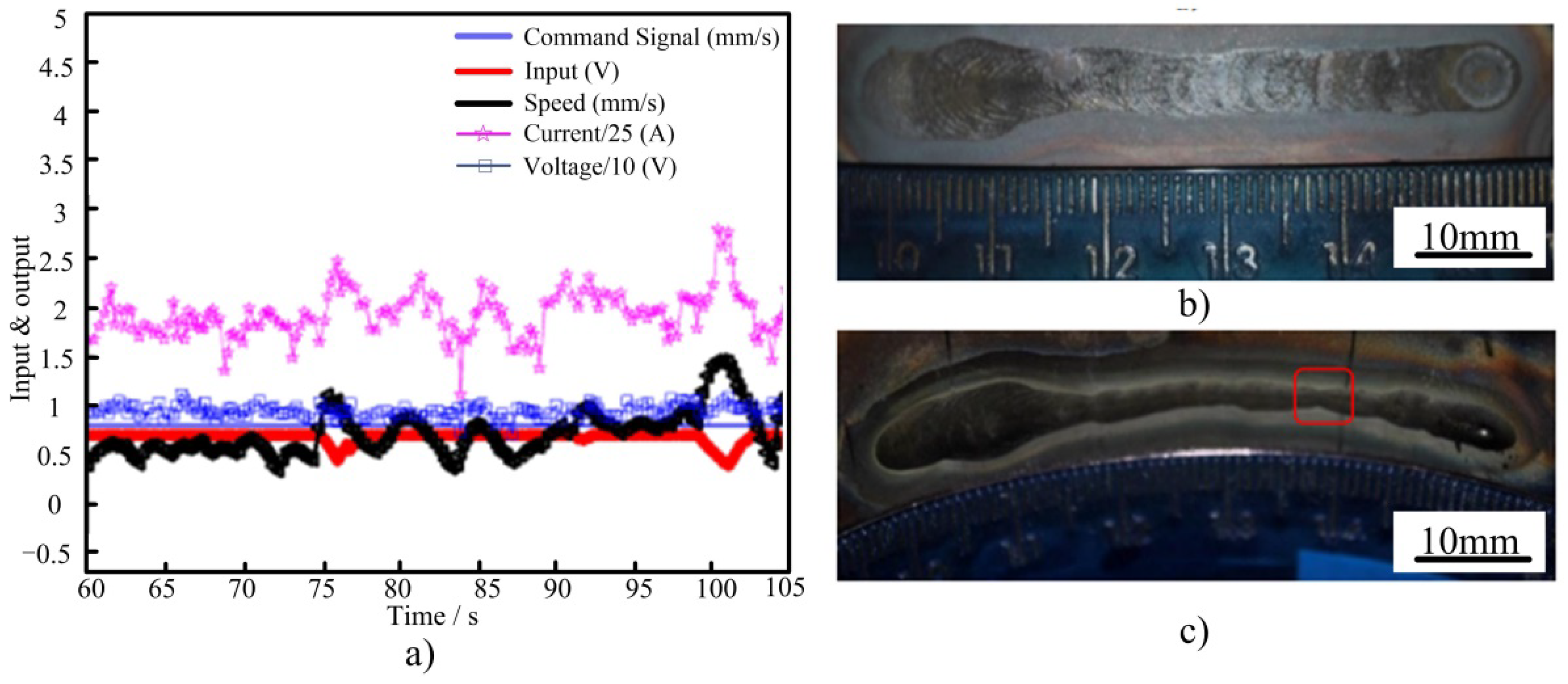
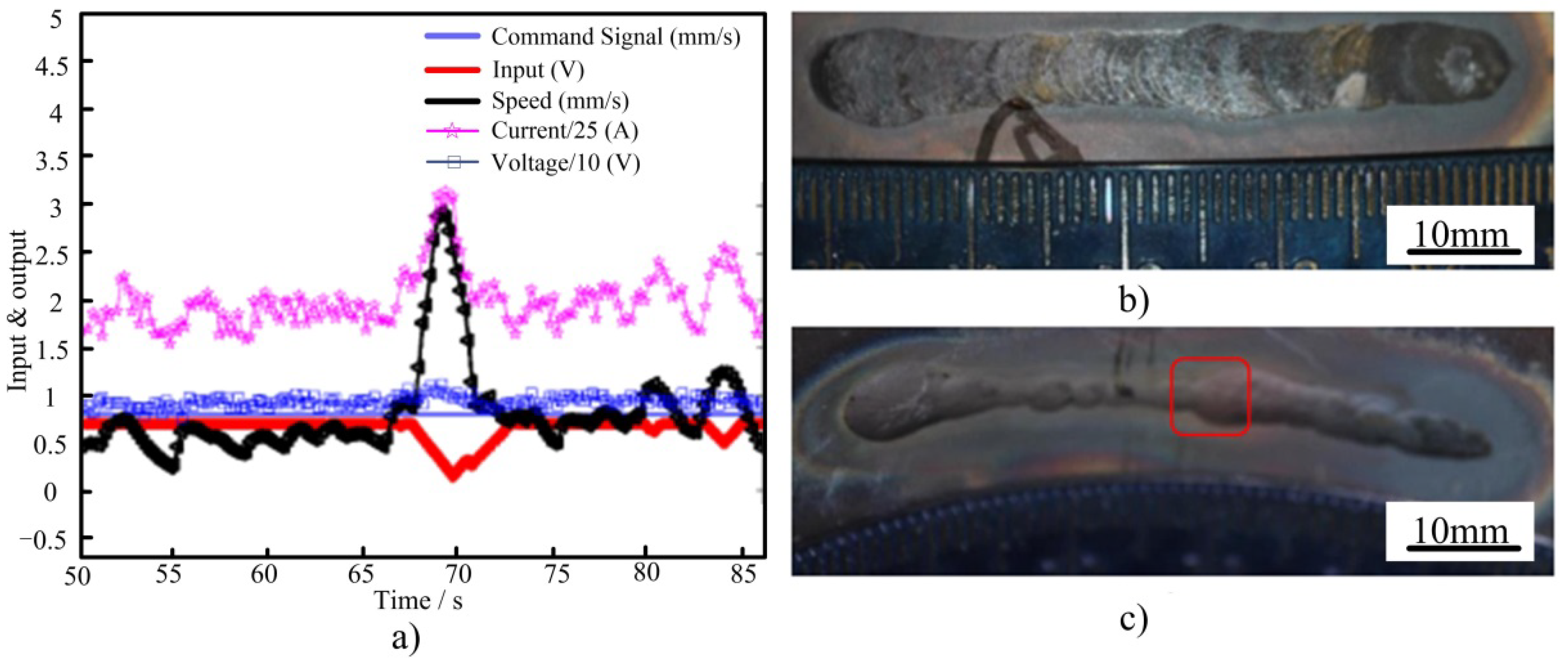
3.2. Speed Control and Current Compensation

The results obtained are shown in Figure 8, Figure 9 and Figure 10. The X-axis in Figure 8, Figure 9 and Figure 10 shows the welding time; the figures show partial curves from all of the data because the characteristics of sensing and control are obvious in these curves. Figure 8a shows the recorded welding process parameters, including the given welding speed (blue solid line), the vibration motor input voltage signal (red solid line with an asterisk), the actual welding speed (black solid line with a triangle), the welding current (pink solid line with a pentagram), and the welding voltage (blue solid line with a box). Figure 8b,c shows the front and back pictures of the weld, respectively.
The first three groups of tests were conducted at a given welding speed of 0.8 mm/s. One group of data was extracted for analysis, and Figure 8a shows that the actual welding speed was well tracked, and the welding current linearly fluctuated with the welding speed, which was well controlled. At 60 s to 75 s, the welding speed is steadily controlled at 0.5 to 0.7 mm/s, which is lower than the given welding speed (0.8 mm/s). At this time, the control system outputs a voltage signal of +0.7 V and commands the welder to speed up, but the welder still maintained the original speed. This phenomenon may be due to the welder focusing on welding and ignoring the command signal. As the actual welding speed is low, if the initial welding current is set to weld, large heat input will result in defects such as the collapse of the molten pool. Therefore, the current compensation function of the designed intelligent controller will play its role, as can be seen in Figure 8a, in which the welding current is around 1.75. After the legend is enlarged by 25 times, the real current is about 44 A, which is lower than the given value (48 A). Therefore, the intelligent controller cooperates with the machine to reasonably match the welding current and ensure the stable heat input in the welding process. At 75 s, an acceleration process occurs and the welding speed is increased to 1 mm/s. At this point, the input voltage signal is reduced accordingly, commanding the welder to slow down, while the welding current is increased accordingly to ensure sufficient heat input in the molten pool. Subsequently, the welder gradually stabilizes, the welding speed fluctuates within a certain of 0.8 mm/s, and the welding current changes accordingly. As seen in the figure, the voltage value fluctuates slightly during the welding process. This is mainly because the welding current changes in real time due to the static characteristics of the welding power supply, resulting in a small change in the welding voltage (about 1 V); however, the impact on the welding shape can be ignored.
The actual welding performance of the system is judged by looking at the front and back pictures of the weld seam in Figure 8, where the appearance of the front side in Figure 8b is good, and a uniform and fine fish scale pattern can be observed. In Figure 8c, the back side is evenly penetrated, with a weld pool width of 3 mm. In reference to the straightedge at 13.8 mm (in the red box), the weld pool width of the back side decreases to 2.3 mm and then increases to 3 mm. Combined with the waveform analysis of the welding speed in Figure 8a, there is a welding speed fluctuation in the welder’s action, and the speed increases to 1.5 mm/s. Although the welding current is increased to 2.5, which is converted to approximately 62.5 A, the welding energy can be maintained in the original penetration state.
Figure 9 shows the results of the second group of tests. As can be seen from Figure 9a, the actual welding speed tracking is good and the welding current fluctuates linearly with the welding speed, which is well controlled. From Figure 9b,c, it is observed that the weld front is well formed with uniform penetration. The fluctuation range of the welding speed is large in magnitude compared to the first group. At 40 s, the actual welding speed was 1 mm/s, which then gradually decreased to 0.4 mm/s at 42 s. The system input voltage signal changed from −0.2 V to +0.35 V, commanding the welder to speed up, and at 43 s, the speed instantly decreased to 0.1 mm/s and then immediately returned to 0.5 mm/s. From the physical sense of the welding operation, it is understandable that there is a momentary pause when the welder moves the torch at this time, which is analyzed in detail at 43 s (in the red box). Because the welding speed sampling frequency of the control system is 4 Hz, as in Figure 9a, the value of the last point before the welding speed drop is defined as the first point of sampling with a speed of 0.4 mm/s, the next sampling speed of 0.2 mm/s, the third point of sampling speed of 0.1 mm/s, the fourth point of sampling speed of 0.3 mm/s, and the fifth point of recovery to 0.5 mm/s, which is caused by the unskilled welder. According to the sampling frequency, the whole process takes 1 s and the current value at the lowest speed point is 1.6, which is converted to 40 A (i.e., the minimum given value). The voltage input signal to the system during the deceleration process is positive and commands the welder to speed up. Therefore, the integrated control of the system corrects the speed deviation of the welder, in addition to reasonably matching the welding current according to the real-time welding speed based on the empirical model of welding current and welding speed, thus minimizing the impact of the welder’s operational errors. The control quality of the control system is confirmed by the front and back pictures of the weld seam in Figure 8b,c. The weld pool width of the back of the weld seam is within the range of 5 to 5.5 mm, and only one significant reduction in the weld pool width is shown in Figure 8c with reference to the straightedge at 12 cm (in the red box), where the weld pool width is measured to be 2.7 mm, which meets the welding quality requirements.
Figure 10 shows the results of the third group of tests. As can be seen from Figure 10a, the actual welding speed tracking effect is good, the overall fluctuation range is small, and the welding current fluctuates linearly with the welding speed, which is well controlled. At 70 s, the actual welding speed controlled by the human welder fluctuates sharply once, with a maximum value of 3 mm/s. The whole acceleration and deceleration process lasts about 4 s. The input voltage signal of the system decreases from +0.7 to 0 V, commanding the welder to slow down, and the actual current value is about 75 A. Combined with the analysis of Figure 10b,c, the front side of the weld seam can be observed, and the overall welding appearance is good. At 70 s, the weld pool width increased from 5 to 6.2 mm, with a slight collapse. Observation of the back of the weld, from 50 to 70 s, shows that the width of the back of the weld pool was 2.3 to 3.2 mm; at 70 s, the back pool width increased significantly, and was measured to be 4.6 mm. This phenomenon is due to the sudden change in the speed of the welder and a linear increase in the welding current, resulting in a large heat input and an increase in the size of the molten pool. Thus, the back pool width increased, but its size was still within the scope of welding quality requirements. Subsequently, under the guidance of the controller, the welding speed controlled by the welder tended to stabilize and remained within the range of 0.8 mm/s. The welding current also fluctuated slightly, and the back pool width of the weld was stabilized at 4 mm, in line with the welding quality requirements.

3.3. Stability Verification

Figure 11 shows the results of the welding test at a welding speed of 1.0 mm/s. It can be observed from Figure 11a that the actual welding speed tracking effect is good, and there is a violent fluctuation of the welding speed at 55 s. The vibration speed of different vibration motors is adjusted through the system input voltage signal to guide the welder to recover to a stable ideal welding speed, and the welding current fluctuates linearly with the welding speed, which is well controlled. By observing the effects of the front and back of the weld from Figure 11b,c, it can be seen that the weld penetration is good. At 55 s, that is, when the welding speed controlled by the human welder fluctuates, the measured weld pool width of the back of the weld is 5.1 mm, which meets the welding quality requirements. After the control system comprehensively controls the welding speed and compensation current, the weld pool width tends to stabilize, and the narrowest point is 2.3 mm, meeting the welding quality requirements.
Figure 12 shows the results of the fifth group of tests. Compared to a welding speed of 0.8 mm/s, the operational requirements of the welder are lower at a welding speed of 1.2 mm/s. The welder controlled the torch more steadily, as can be seen from the results in Figure 12a, and there were no transient torch stops or violent torch fluctuations. By adjusting the output of the welding power supply through the controller, the welding current fluctuates linearly with the welding speed, compensating for heat input variations caused by welding speed deviations caused by the human welder. The weld seam formation in Figure 12b,c shows good penetration with a back pool width of 4.2 to 2.3 mm. Figure 12c shows two decreases in weld pool width, combined with the waveform analysis of the welding speed and the welding current in Figure 12a, where the welding speed is low at 67 and 74 s. Thus, the welding current is reduced accordingly, and the heat input is transiently low, but the back weld pool width meets the weld requirements.
The average welding speeds of the above welding tests were organized, as shown in Table 3, with the highest experimental error of 7.6% in the first group and the lowest error of 0.4% in the fifth group, indicating the average speed was well controlled. During the welding process, because of the natural shaking of the unskilled human welder’s hand, the instantaneous speed fluctuates in a certain range, while the effect of fluctuations in welding speed on heat input is eliminated by the current compensation function of the system controller. As seen from the above test results, mis-operations occur with a very low probability during the welding process operation, such as momentary pauses or violent shaking. These human uncertainties in the system control variable and the welder’s speed deviation can be corrected through the integrated control of the system. Based on the empirical model of the welding current and the welding speed, the welding current is reasonably matched according to the real-time welding speed, minimizing the impact of the welder’s operational errors and achieving an ideal and uniform full penetration weld, and thus relieving the dependence on skills for junior welders to weld in the field.
The main purpose of this study was to verify the effectiveness of the control idea. Only the current and speed were considered in the welding process, and the quality penetration was judged only by looking at the front and the back of the welding line. Other parameters in the welding process and quality parameters in weld characterization will be included in subsequent studies. The machine–human cooperative control welding system proposed in this paper provides a research direction for effectively solving the problem of the shortage of welders and for helping unskilled welders to produce quality welds, and lays the foundation for developing the next generation of machine–human cooperative intelligent welding system.

4. Conclusions

  • A model of the relationship between the welding current I and the welding speed s was obtained through a virtual reality welding system by learning the operational experience of skilled welders, i.e., through their empirical skills in regulating the welding speed under different welding current conditions.
  • With the current compensation function of the system controller, the welding current fluctuates linearly with the welding speed, eliminating the effect of fluctuations in welding speed on the heat input.
  • The addition of the current compensation function caused small fluctuations in weld voltage (around 1 V) and had little effect on weld penetration.
  • The machine–human cooperative control system designed in this paper lays the foundation for the development of a next-generation machine–human cooperative intelligent welding system by relieving the human welders’ reliance on empirical skills through machine decision making and welder implementation.

Author Contributions

Conceptualization, Z.Y., X.Z. and N.H.; methodology, J.Z.; validation, Z.Y., X.Z., J.Z. and N.H.; investigation, Z.Y. and T.Z.; resources, J.Z., X.Z. and N.H.; data curation, Z.Y., X.Z., T.Z. and N.H.; writing—original draft preparation, Z.Y.; writing—review and editing, N.H.; visualization, N.H. and J.Z.; All authors have read and agreed to the published version of the manuscript.

Funding

This work is supported by Beijing Nova Program (Z201100006820101), National Natural Science Foundation of China (U1937207), National Natural Science Foundation of China (No.51875004), Beijing Natural Science Foundation (No.3172004).

Institutional Review Board Statement

Not applicable.

Informed Consent Statement

Not applicable.

Data Availability Statement

Not applicable.

Conflicts of Interest

The authors declare no conflict of interest.

References

  1. David, S.A.; DebRoy, T. Current issues and problems in welding science. Science 1992, 257, 497–502. [Google Scholar] [CrossRef]
  2. Li, L.; Wang, X.; Huang, Y. Analysis of In Situ Optical Signals during Laser Metal Deposition of Aluminum Alloys. Crystals 2021, 11, 589. [Google Scholar] [CrossRef]
  3. Yan, Z.Y.; Chen, S.J.; Jiang, F.; Zheng, X.; Tian, O.; Cheng, W.; Ma, X. Effect of Asymmetric Material Flow on the Microstructure and Mechanical Properties of 5A06 Al-Alloy Welded Joint by VPPA Welding. Metals 2021, 11, 120. [Google Scholar] [CrossRef]
  4. Liu, J.; Sun, J.; Wei, S.; Lu, S. The Effect of Nickel Contents on the Microstructure Evolution and Toughness of 800 MPa Grade Low Carbon Bainite Deposited Metal. Crystals 2021, 11, 709. [Google Scholar] [CrossRef]
  5. Kagermann, H.; Helbig, J.; Hellinger, A. Recommendations for Implementing the Strategic Initiative INDUSTRIE 4.0: Securing the Future of German Manufacturing Industry; Final Report of the Industrie 4.0 Working Group; Forschungsunion: Enschede, The Netherlands, 2013. [Google Scholar]
  6. Uttrachi, G.D. Welder Shortage Requires New Thinking; American Welding Society: Miami, FL, USA, 2007. [Google Scholar]
  7. Liu, Y.K.; Zhang, Y.M. Toward welding robot with human knowledge: A remotely-controlled approach. IEEE Trans Actions Autom. Sci. Eng. 2014, 12, 769–774. [Google Scholar] [CrossRef]
  8. Zhang, W.J.; Zhang, Y.M. Modeling of Human Welder Response to 3D Weld Pool Surface: Part I—Principles. Weld. J. 2012, 91, 310s–318s. [Google Scholar]
  9. Hang, W.J.; Zhang, Y.M. Modeling of Human Welder Response to 3D Weld Pool Surface: Part II—Results and Analysis. Weld. J. 2012, 91, 329s–337s. [Google Scholar]
  10. Guu, A.C.; Rokhlin, S.I. Arc weld process control using radiographic sensing. Mater. Eval. 1992, 50, 1344. [Google Scholar]
  11. Andersen, K. Synchronous Weld Pool Oscillation for Monitoring and Control. Ph.D. Thesis, Vanderbilt University, Nashville, TN, USA, 1993. [Google Scholar]
  12. Hartman, D.A. Intelligent Control in Arc Welding: Intelligent Engineering Systems through Artificial Neuro Networks; ASME: New York, NY, USA, 1999. [Google Scholar]
  13. Ohshima, K.; Yamamoto, M.; Tanii, T.; Yamane, S. Digital control of torch position and weld pool in MIG welding using image processing device. IEEE Trans. Ind. Appl. 1992, 28, 607–612. [Google Scholar] [CrossRef]
  14. Zhang, Y.M.; Kovacevic, R.; Wu, L. Dynamic analysis and identification of gas tungsten arc welding process for weld penetration control. J. Eng. Ind. -Trans. ASME 1996, 118, 123–136. [Google Scholar] [CrossRef]
  15. Zhang, Y.M.; Kovacevic, R. Neurofuzzy model-based predictive control of weld fusion zone geometry. IEEE Trans. Fuzzy Syst. 1998, 6, 389–401. [Google Scholar] [CrossRef]
  16. Boo, K.S.; Cho, H.S. A self-organizing fuzzy control of weld pool size in GMA welding process. Control Eng. Pract. 1994, 2, 1007–1018. [Google Scholar] [CrossRef]
  17. Banerjee, P.; Govardhan, S.; Wikle, H.C.; Liu, H.Y.; Chin, B.A. Infrared sensing for on-line weld geometry monitoring and control. J. Eng. Ind.-Trans. ASME 1995, 117, 323–330. [Google Scholar] [CrossRef]
  18. Rokhlin, S.I.; Guu, A.C. A study of arc force, pool depression, and weld penetration during gas tungsten arc welding. Weld. J. 1993, 72, 381s–390s. [Google Scholar]
  19. Kovacevic, R.; Zhang, Y.M. Real-time image processing for monitoring of free weld pool surface. ASME J. Manuf. Sci. Eng. 1997, 119, 161–169. [Google Scholar] [CrossRef]
  20. Liu, Y.K.; Zhang, Y.M.; Kvidahl, L. Skilled Human Welder Intelligence Modeling and Control: Part 1—Modeling. Weld. J. 2014, 93, 46s–52s. [Google Scholar]
  21. Liu, Y.K.; Zhang, Y.M.; Kvidahl, L. Skilled Human Welder Intelligence Modeling and Control: Part II—Analysis and Control Applications. Weld. J. 2014, 93, 162s–170s. [Google Scholar]
  22. Liu, Y.K.; Shao, Z.; Zhang, Y.M. Learning Human Welder Movement in Pipe GTAW: A Virtualized Welding Approach. Weld. J. 2014, 93, 388s–398s. [Google Scholar]
  23. Chen, S.J.; Huang, N.; Liu, Y.K.; Zhang, Y.M. Machine-Assisted Travel Speed Control in Manual Welding Torch Operation. Int. J. Adv. Manuf. Technol. 2015, 76, 1371–1381. [Google Scholar] [CrossRef]
  24. Chen, S.J.; Huang, N.; Liu, Y.K.; Zhang, Y.M. Machine Assisted Manual Torch Operation: System Design, Response Modeling, and Speed Control. J. Intell. Manuf. 2016, 28, 1249–1258. [Google Scholar] [CrossRef]
  25. Liu, Y.K.; Zhang, W.J.; Zhang, Y.M. Adaptive neuro-fuzzy inference system (ANFIS) modeling of human welder’s response to 3D weld pool surface in GTAW. J. Manuf. Sci. Eng.-Trans. ASME 2013, 135, 0210101–02101011. [Google Scholar] [CrossRef]
  26. Liu, Y.K.; Zhang, W.J.; Zhang, Y.M. Dynamic neuro-fuzzy based human intelligence modeling and control in GTAW. IEEE Trans. Autom. Sci. Eng. 2014, 12, 324–335. [Google Scholar] [CrossRef]
  27. Chandrasekhar, N.; Vasudevan, M.; Bhaduri, A.K.; Jayakumar, T. Intelligent modeling for estimating weld bead width and depth of penetration from infra-red thermal images of the weld pool. J. Intell. Manuf. 2013, 26, 59–71. [Google Scholar] [CrossRef]
  28. Zhang, W.J.; Liu, Y.K.; Wang, X.; Zhang, Y.M. Characterization of Three-Dimensional Weld Pool Surface in GTAW. Weld. J. 2012, 91, 195s–203s. [Google Scholar]
  29. Pandremenos, J.; Chryssolouris, G. A neural network approach for the development of modular product architectures. Int. J. Comput. Integr. Manuf. 2011, 24, 879–887. [Google Scholar] [CrossRef]
  30. Yan, Z.Y.; Chen, S.J.; Jiang, F.; Zhang, W.; Huang, N. Study and optimization against the gravity effect on mechanical property of VPPA horizontal welding of aluminum alloys. J. Manuf. Process. 2019, 46, 109–117. [Google Scholar] [CrossRef]
  31. Yan, Z.Y.; Chen, S.J.; Jiang, F.; Zhang, W.; Huang, N.; Chen, R. Control of gravity effects on weld porosity distribution during variable polarity plasma arc welding of aluminum alloys. J. Mater. Process. Technol. 2020, 282, 116693. [Google Scholar] [CrossRef]
  32. Vora, J.; Patel, V.K.; Srinivasan, S.; Chaudhari, R.; Pimenov, D.Y.; Giasin, K.; Sharma, S. Optimization of Activated Tungsten Inert Gas Welding Process Parameters Using Heat Transfer Search Algorithm: With Experimental Validation Using Case Studies. Metals 2021, 11, 981. [Google Scholar] [CrossRef]
  33. Liu, Y.K.; Huang, N.; Zhang, Y.M. Human Welder Intelligent Modeling and Control Using Virtualized Welding Platform. In Proceedings of the Technical Program for Annual FABTECH International & AWS Welding Show, Atlanta, GA, USA, 10–13 November 2014. [Google Scholar]
Figure 1. General view of the virtualized welding system [23], (a) schematic diagram, (b) real picture.
Crystals 12 00235 g001
Figure 2. Welder controlled process, i is the input current, i* is the output current.
Crystals 12 00235 g002
Figure 3. Cooperative control principle of machine–human cooperative GTAW welding process, i is the input current, i* is the output current.
Crystals 12 00235 g003
Figure 4. (a) Naked eye view of the work piece, (b) virtual view of the mock-up.
Crystals 12 00235 g004
Figure 5. Sample images from the camera with different welding currents.
Crystals 12 00235 g005
Figure 6. Nine welding experiments with different welding current values [23].
Crystals 12 00235 g006
Figure 7. Data points and linear fitting result [23].
Crystals 12 00235 g007
Figure 8. Results of welding experiment I at 0.8 mm/s: (a) welding parameters, (b) front, (c) back.
Crystals 12 00235 g008
Figure 9. Results of welding experiment II at 0.8 mm/s: (a) welding parameters, (b) front, (c) back.
Crystals 12 00235 g009
Figure 10. Results of welding experiment III at 0.8 mm/s: (a) welding parameters, (b) front, (c) back.
Crystals 12 00235 g010
Figure 11. Welding experiment results at 1.0 mm/s: (a) welding parameters, (b) front, (c) back.
Crystals 12 00235 g011
Figure 12. Welding experiment results at 1.2 mm/s: (a) welding parameters, (b) front, (c) back.
Crystals 12 00235 g012
Table 1. Welding parameters.
Welding Current (A)Welding Speed (mm/s)Arc Height (mm)Gas Flow (L/min)
45, 50, 55-411.8
Table 2. Welding parameters in the M-H collaborative GTAW.
No.Welding SpeedWelding CurrentArc Height Gas FlowBack Shielding Flow
1–30.8 mm/s48 A3 mm12 L/min15 L/min
41.0 mm/s50 A3 mm12 L/min15 L/min
51.2 mm/s52 A3 mm12 L/min15 L/min
Table 3. Average speed in the M-H collaborative GTAW.
No.Welding Speed (mm/s)Average Speed (mm/s)Error (%)
10.80.7397.6
20.80.8425.2
30.80.7535.9
41.01.0747.4
51.21.9560.4
Publisher’s Note: MDPI stays neutral with regard to jurisdictional claims in published maps and institutional affiliations.

