Review

In Situ Analytical Methods for the Characterization of Mechanochemical Reactions

by
Claudia Weidenthaler
Max-Planck-Institut für Kohlenforschung, Heterogeneous Catalysis, Kaiser Wilhelm-Platz 1, D-45470 Mülheim an der Ruhr, Germany
Crystals 2022, 12(3), 345; https://doi.org/10.3390/cryst12030345
Submission received: 15 February 2022 / Revised: 23 February 2022 / Accepted: 1 March 2022 / Published: 2 March 2022
(This article belongs to the Special Issue Frontiers of Applied Crystal Chemistry)

Abstract

:
The interest in mechanochemical reactions and their fields of application have increased enormously in recent times. Mechanically activated reactions offer the advantage of cost-efficiency as well as environmentally friendly syntheses routes. In contrast to thermally induced processes, the energy transfer via the milling media takes place on a local scale. This leads to unique reaction pathways, which often also result in the formation of metastable phases. For the understanding of reaction pathways on a mechanistic level, it is very important to follow the processes taking place in the grinding jar during milling. Besides the measurement of pressure and temperature changes during a mechanochemical reaction, in situ high energy synchrotron X-ray powder diffraction and Raman spectroscopy experiments have been successfully implemented over the last 10 years. This review will highlight the developments which were achieved in the field of in situ monitoring of mechanochemical reactions and their input to the understanding of mechanochemistry.

1. Introduction

According to the International Union of Pure and Applied Chemistry (IUPAC), the term mechanochemistry refers to any chemical reaction that is induced by the direct absorption of mechanical energy [1]. During mechanochemical processes, the input of mechanical energy is used to initiate and/or accelerate chemical reactions and/or induce amorphization and/or structural transformations [2].
While this review is not intended to provide an overview of the history of mechanochemistry, some historical milestones will nevertheless be mentioned to illustrate the importance of the method. Even though mechanochemical transformations have been used already in the Neolithic, the first written report was published 315 B.C. by Theophrastus of Eresus [3]. The book contains a reference for the reduction of native cinnabar (mercuric sulfide, HgS) in a copper mortar and a copper pestle with vinegar to the liquid metal mercury. In the 19th century, M. Carey-Lea observed the decomposition of silver halides by introducing mechanical forces. In his paper, he described his conclusions “It has now been shown, as I believe for the first time, that mechanical force is competent, without the aid of heat~ to break up a molecule that owes its existence to an exothermic reaction” [4]. The first report of a mechanically induced organic chemical reaction is probably the work of Ling and Baker in 1893 [5]. By grinding the educts in a mortar, they prepared different halogen derivatives.
At the beginning of the 20th century, the name mechanochemistry was applied to chemical reactions which are affected by the input of mechanical energy. Mechanochemistry was established as an individual branch of chemistry when it first appeared in 1919 in the classification of a textbook by Ostwald [6]. The term “mechanochemistry” was included in his chemical systematics, together with thermochemistry, electrochemistry, and photochemistry. During the first half of the 20th century, mechanochemistry was not much in the focus of scientific research, but it was already used in industrial processes such as hydrometallurgy or concrete production [7]. Mechanochemistry became more and more popular in the second half of the 20th century and has finally experienced a kind of revival in recent years. This was maybe also triggered when IUPAC considered mechanochemistry amongst the “10 chemical innovations that will change our world” [8]. Excellent reviews of the history of mechanochemistry, mechanochemistry in general, and applications are recommended for further reading [3,9,10,11,12,13,14,15,16].
Especially for organic synthesis, mechanochemistry is an elegant alternative approach for a cleaner, faster, and more efficient “green” synthesis compared to a conventional one using solvents [12]. To date, mechanochemistry has been reported for the synthesis of organic as well as inorganic materials [16]. Particular attention has been paid to the synthesis of metal alloys, oxides, pharmaceuticals, co-crystals, and large porous framework structures such as MOFs or ZIFSs, to name but a few. Some examples, out of many others for the application of mechanochemistry, are material synthesis [17,18,19], structural phase transformations [20,21,22,23], amorphization [24,25], oxidation and reduction reactions, hydrogenation or nitridation [26,27], alloying [28,29,30], intercalation [31,32], and catalytic reactions [33,34,35].
The hallmark of mechanochemistry is achieving chemical transformations by milling or grinding, without the need for bulk dissolution of reactants. An important feature of mechanochemistry is the performance of chemical transformations by milling without the need for solvents or extra heat sources. Besides the simple use of mortar and pestle, different types of mills or extruders are nowadays used to generate the mechanical energy input required for chemical reactions [14,36,37].
Among the mills, vibration/shaker and planetary mills are most commonly used in the laboratory [14]. The milling jars, as well as the balls, are available in different materials with different hardness, such as stainless steel, agate (SiO2), tungsten carbide, silicon nitride, corundum, zirconia, or polymers (Perplex, PMMA).
The way in which energy is introduced to a reaction, namely by the collision of the grinding media with the sample, leads to mechanochemical reactions and pathways, which may differ from thermally activated ones [14,38]. Several models exist to describe mechanically activated chemical processes. The model covers different aspects such as the increase of the local temperature as in the hot-spot theory, the impact of stress in the spherical model, or the formation of fresh surfaces in the theory of short-living active centers [10]. The events leading to a mechanically activated reaction are locally restricted, since they are limited to the contact points of the substance with the milling media and adjacent particles. In addition, mechanochemical reactions show an experimentally observable far-from-equilibrium behavior. This explains the formation of thermodynamically unfavorable phases which is typical for mechanochemical reactions [14,38]. Understanding reaction pathways on a mechanistic level requires techniques that provide direct insights into processes that take place during milling. This can be realized by the implementation of in situ or operando characterization techniques coupled to the milling experiment.
This review will focus on the challenges associated with in situ mechanochemical studies. The milestones in the successful developments of different in situ techniques that enable monitoring of mechanochemical reactions, and the gain of information provided by such experiments, will be summarized.

2. Methods for In Situ Characterization during Mechanochemical Reactions

Nowadays it is widely accepted that the characterization of materials before and after reactions is, in many cases, not sufficient to understand their chemical and physical properties under reaction conditions. This so-called ex-situ characterization has the disadvantage of not being representative of the actual state of a material or compound under reaction or real operating conditions. Reactions are interrupted and air-sensitive phases may change during or after preparation. Moreover, intermediates or metastable phases can be missed. For this reason, in situ investigations have become more and more popular during the last decades. The applications for in situ investigations, in general, are very diverse. Depending on the characterization technique, in situ studies can provide information about processes on atomic, molecular, or crystalline length scales. Following reactions can help to identify the influence of different parameters such as temperature, pressure, chemical composition, or pH value on reaction pathways. Depending on the characterization method, the formation of metastable intermediates, formation of polymorphs, amorphization, microstructure changes, quantitative phase changes, and/or structural phase transformations can be monitored. In situ techniques enable the investigation of structural stabilities as well as dynamic processes and therewith of the kinetics of a reaction.
Modern analytical tools facilitate studies under real operating conditions (operando) by simultaneous analysis of, for instance, structural or electronic properties and their performances such as reaction rates of catalysts or charging/discharging reactions taking place in batteries [39,40]. While in situ studies evaluate structure–property relationships, operando studies study structure–performance relations [41]. To describe structure–property–performance relations comprehensively, it could be also important to apply more than only one analytical method. The combination of different tools probing structures on different length scales together with performance values is required to get a complete picture of structure–property relationships.
The in situ characterization of materials can be very challenging, depending on the reaction conditions and experimental setup. Usually, samples are prepared in sample environments (sample cells) that are specifically designed for a particular experiment. For operando experiments, the samples are analyzed in the setup that corresponds to the real application. To take up the already chosen example again, electrode materials in battery cells have been studied by in situ diffraction experiments during charging and discharging. The interpretation of experimental data can be complicated if the analysis is disturbed by the surrounding sample environment. For this reason, it is very important to consider beforehand which analytical method will be best for the corresponding in situ experiment.
Transferring these challenges for in situ studies in general to mechanochemical applications, it becomes clear that the sample environment (jars), the milling media (balls), and the movement of the milling vessels will make in situ studies difficult. Depending on the material used for the construction of jars, their walls can be thick and penetration with a certain analytical probe such as an X-ray or laser beam might be difficult. Therefore, detailed mechanistic studies of milling reactions were limited for a long time to the analysis of temperature and pressure changes inside the milling vessels. Both types of measurements are indirect methods to monitor mechanochemical reactions. If volatile components are released or incorporated into the structures during the reaction, the pressure changes can be measured. Simultaneous temperature and pressure measurements were performed during milling of titanium-doped NaAlH4, a solid-state hydrogen storage material [42]. A commercial planetary mill had been modified in a way that the one-step direct hydrogenation could be monitored under milling, allowing process parameters such as temperature and pressure to be recorded in situ. On the other hand, a temperature increase is an indication of an exothermic reaction. Examples are self-sustaining reactions taking place during mechanical activation of exothermic powder mixtures [43]. The first self-sustaining reactions of metal sulfides in a ball mill was described by Tschakarov et al. [44,45]. Milling of Zn or Sn/Fe and S led to an explosive reaction and products comparable to those obtained by high-temperature synthesis. At those times, it was difficult to follow the reactions in the vessel in situ. The only possibility to monitor any changes taking place in the agar vessel was the simultaneous detection of temperature changes of the gas medium in the vessel during milling. From changes in the thermograms, it was possible to infer the reaction mechanism. For gas–solid reactions such as hydrogenation, oxidation, or nitridation, the reduction of the gas pressure during milling has been observed. Ogino et al. reported the nitridation of Ti and Al powders during ball milling in nitrogen gas [28]. The amount of adsorbed nitrogen was determined from the recorded pressure reduction during the reaction. For this purpose, the milling vessel was connected to a pressure gauge. Based on the pressure changes, the composition of the respective nitrides and the reaction kinetics could be determined.
The limitation of in situ studies to pressure and temperature measurements was overcome when the first in situ X-ray diffraction (XRD) and spectroscopy techniques could be implemented, which allowed the monitoring of reactions in real-time. While it is straightforward to study, say, the formation of metal oxides in a tubular glass reactor by XRD techniques, it is complicated to investigate materials in stainless steel vessels during mechanosynthesis by conventional laboratory diffraction experiments. The steel walls of commercial milling vessels have usually a thickness of several millimeters, which leads to a significant if not total adsorption of the X-ray beam. In addition, the balls will also interfere with the X-ray beam which can cause additional absorption effects. If alternative vessel materials are used as shown in the following, the scattering contribution from the walls can add a very high background to the measured powder patterns.
In 2013, Friscic and co-workers were the first to report real-time studies of mechanochemical transformations utilizing in situ high-energy synchrotron diffraction studies [46,47]. The authors had the idea of simply mounting a commercial shaker mill (Retsch MM200) on a diffractometer (Figure 1a) [48]. This did not sound practical at first due to the movement of the grinding vessels and the geometry of the shaker mills (the vessels are shielded from the beam by the mill housing). However, the team found a solution to mount the mill on beamline ID15B available at the European Synchrotron Radiation Facility (ESRF). They modified the arms holding the vessels in such a way that the vessels could be adjusted in the X-ray beam (Figure 1a, red arrow). In addition, the authors changed from stainless steel vessels to polymer jars which can be penetrated by high-energy X-ray radiation at a synchrotron (~90 keV).
Polymethyl methacrylate (PMMA, Perspex®) was used as material for the milling vessels (Figure 1b). The vessels with 3 mm thick walls allow penetration of incoming and outgoing X-ray beams without too high absorption. The scattering of PMMA results in a broad background, characteristic for amorphous polymers. However, the background scattering does not disturb the qualitative phase analysis. As will be discussed later in the text, the amorphous background from the jar is an issue if amorphization needs to be analyzed quantitatively.
With this modified setup, the formation of a metallorganic framework, ZIF-8, could be studied during synthesis using liquid-assisted grinding (LAG) and milling with an ionic species together with liquid-assisted grinding (ILAG). The reactions were conducted at 30 Hz in vessels with a volume of 10 mL using two stainless-steel balls with 7 mm diameter. Figure 2a,b shows the in situ powder patterns collected during LAG and ILAG. The analysis of the intensity changes of the main 211 reflections of ZIF-8 reveals a different crystallization behavior depending on the presence of the ionic species (Figure 2c). The presence of 3 mol% of NH4NO3 enhances the reaction rate and ZIF-8 appears immediately after starting the reaction, while for the LAG reaction, an induction period of 2 min was observed.
As already mentioned above, the amorphous scattering contribution of the polymer jar can falsify the quantitative analysis of the amorphous sample fraction. In a follow-up paper, Halaz et al. studied how the use of an internal standard can correct for the fluctuations of the measured reflection intensities caused by the non-uniform distribution of the sample in the milling vessel [49]. The aim of the study was the evaluation of quantitative analysis of crystalline phases by the Rietveld method and the determination of the amorphous content in a progressing mechanochemical reaction. As with conventional diffraction experiments, the addition of an internal standard is recommended for in situ experiments. This allows correction of experimentally induced peak shifts as well as intensity fluctuations due to inhomogeneous sample distribution. For a determination of the amorphous fraction using the Rietveld method, the admixture of a defined amount of internal standard is essential.
Further development of in situ X-ray analytics was the exploration of the temperature influence on the synthesis of coordination polymers [50]. For this experiment, reactants and milling media (balls) were placed in the vessels and preheated in an external furnace. When the desired temperature was reached, the reaction vessels were closed and placed in a thermally insulating, nondiffracting casing (Figure 3).
Figure 3. PMMA reaction vessel in an insulating housing for in situ X-ray diffraction monitoring of mechanochemical reactions at elevated temperatures. The X-ray beam is passing the vessel through the bottom, indicated by the illustrated red circular cross-section. The arrows indicate the direction of the vessel movement during milling. Adapted with permission from [51]. Copyright 2016, American Chemical Society.
Crystals 12 00345 g003
This setup makes temperature control challenging because heat will be generated by the mechanical interaction of the balls with the sample and walls and at the same time heat will be lost to the cooler environment. The authors note that the temperature control by using an external flow cooling jacket was not practical, as it would have limited the ability to acquire in situ XRD data.
Tumanov et al. used 3D printing for the production of polymer vessels optimized for low background scattering, absorption, and angular resolution in X-ray powder diffraction experiments [52]. The vessel made of polymethyl methacrylate (PMMA) results in a relatively high background with three broad scattering maxima (Figure 4, Type 0). The background of the printed polylactic acid (PLA) jars is lower, depending on the wall thickness (Figure 4, Types 1–4), but colorants of the polymer cause low-intensity reflections. The PLA vessels showed good mechanical strength and are more resistant to solvents than PMMA. Both properties are very important for numerous chemical reactions, as will be discussed later.
One problem in obtaining high-quality in situ diffraction data is the large diameter of the vessels with the sample distributed over the entire vessel volume. All crystallites in this volume will contribute to the diffraction pattern. Keeping the geometric conditions in mind, which need to be fulfilled for diffraction, only the crystallites within the focusing point cause meaningful diffraction. All crystallites outside this area will violate the focusing conditions. Simply spoken, the measured reflections are broadened, shifted to different angles, or even split into two peaks. The sample fractions staying close to the two opposite walls cause reflections that appear at different angles depending on which side of the vessel they originate. To overcome this problem, Lampronit et al. designed miniaturized 1.8 mL PMMA milling vessels [53]. In combination with an optimized sample positioning, they could improve data quality and avoid intensive peak splitting due to “sample displacement” or diffraction from samples adhered at the opposite walls of the jar.
Ban et al. reconsidered the vessel design because, as already mentioned, diffraction from a large sample volume results in a significant broadening of reflections, which makes precise analysis difficult [54]. Another goal was to collect diffraction data with an improved signal-to-noise ratio. To solve these problems, a new type of in situ ball milling setup was developed. The milling jars consist of two stainless-steel half-shells with a hemispherical central part where milling takes place (Figure 5a). The inner part is surrounded by a perforated circular part defining the probing chamber. This part is covered by a thin polymer film (Figure 5b), and its depth is defined by the Teflon ring. The idea of the new design is to only analyze the sample within the probing area and not the powder in the large milling vessel (Figure 5c). The balls cannot access this probing area and therefore the walls of the probing chamber can be made of a thin polymer foil such as Kapton. As an advantage of the thin window, less hard X-rays can then be used. The mill was mounted on the X04SA Materials Science (MS) beamline (15) at the Swiss Light Source (SLS), Paul Scherrer Institute (Figure 5a). The scheme of the sample vessel and motion principles are shown in Figure 5b. It is important to mention that this mill setup has a motion that is different to shaker mills as the sample vessel is vigorously shaking and slowly rotating. The powder patterns show that peak width and background scattering can be improved by this setup (Figure 6).
However, this requires an efficient and fast exchange of sample between the main vessel and the volume used for analysis. The setup cannot avoid that some sample is compacted and fixed in the probing area. Since a part of the sample is analyzed which is not in direct contact with the milling media, it cannot be guaranteed that the experimental results represent the material in the state of mechanical activation.
Another type of mill, the vibration mill Pulverisette 23 from Fritsch GmbH (Idar-Oberstein, Germany), was used by the Emmerling group for in situ XRD experiments [55]. Since the shaking movement, vertical instead of horizontal, and the volume of the vessel are different to the Retsch MM200/400 mills, the Pulverisette and MM200/400 are not directly comparable. 10 mL grinding jars made of Perspex (Figure 7a) and two stainless-steel balls (4 g, diameter 10 mm) were used for the synthesis of ZIF-8. The in situ XRD experiments were performed at the μSpot beamline at BESSY II, Helmholtz Centre Berlin for Materials and Energy, and frames were collected every 30 s (Figure 7b).
So far, the published in situ XRD studies have been mainly performed in polymer vessels. The synthesized coordination polymers, pharmaceuticals, or co-crystals can be considered soft materials. For in situ XRD and Raman studies of soft materials, jars of poly(methyl methacrylate) (PMMA) could be used. As already discussed, the polymer is transparent for high energy X-ray and laser beams. However, the use of polymer jars is problematic for the synthesis of hard materials, or a correct analysis of product gases formed during mechanocatalytic reactions. The mechanochemical transformation of boehmite, γ-AlOOH, into high-surface-area corundum, α-Al2O3, requires the use of tungsten carbide or stainless-steel milling vessels [56,57]. The large wall thickness in turn presents a challenge for in situ investigations in steel grinding jars. Rathmann et al. could show that reactions of hard materials in the existing polymer milling vessels failed due to insufficient energy input. A simple modification of the stainless-steel vessels by cutting two windows into the walls and covering the windows with polymer failed. The use of the polymer windows changed the energy impact of the balls on the powder and the walls, which resulted in incomplete reactions. In addition, relatively large balls (15 mm diameter) were required, and this led to a decomposition of the PMMA windows. The polymer decomposition could be monitored by an infrared spectrometer that was connected to the milling vessel (Figure 8a). After 5 min. milling, the intensity of the CO2 bands increased as well as bands related to hydrocarbons (sp3-hybridized), ester groups (1750 to 1735 cm−1), and keto groups (1140 to 1240 cm−1). These modes are typical for the methyl methacrylate, which the monomer PMMA is formed of. The decomposition products can falsify many catalytic reactions which are performed in a ball mill. Therefore, alternatives were explored, and finally, a window composed of a PMMA ring protected by a thin 0.5 mm tick steel inset allowed the successful monitoring of the solid-state transformation (Figure 8b).
The studies on the mechanochemistry of hard materials also showed that for such materials, small geometrical changes of the mill can already have a negative influence on the reactions. For example, simply extending the specimen holder proved to be insufficient because changes in mechanical forces need to be considered for the construction of optimized extensions. Petersen et al. combined in situ synchrotron diffraction experiments with pressure measurements performed during the formation of ZnS from its elements in a stainless-steel jar equipped with a PMMA window [58]. Milling in a PMMA vessel failed because the large stainless-steel ball required for appropriate high energy input simply destroyed the PMMA vessel after some minutes (Petersen, private communication). Milling Zn and S8 results in the sublimation of S8, observed by a sudden pressure increase. Simultaneously, the formation of the hexagonal metastable ZnS modification (wurtzite) could be observed by in situ XRD. Immediately after the formation of hexagonal wurtzite, the structural phase transformation to the thermodynamic stable cubic sphalerite takes place. This work also shows that reactions may differ depending on the used mill. While previous experiments performed in a planetary mill showed the formation of amorphous intermediates [59], no additional intermediates could be observed during the in situ X-ray experiments performed in the shaker mill [58].
X-ray diffraction is the appropriate method to follow changes of crystalline phases [60]. However, amorphization during ball-milling leads to the formation of non-crystalline compounds which cannot be analyzed by conventional diffraction experiments. Vibrational spectroscopy (Fourier transformed infrared spectroscopy, Raman spectroscopy) is a tool for the analysis of amorphous or liquid phases. Lin et al. used a portable fiber-optic Raman spectrometer to investigate the co-crystal formation during mechanosynthesis in the solid-state indomethacin–saccharin or theophylline–citric acid systems [61]. Since they stopped the grinding process and analyzed the sample with a portable Raman analyzer, this cannot be considered a “real” in situ experiment.
Gracin et al. implemented, for the first time, in situ time-resolved laboratory Raman scattering directly to the milling process by coupling a Raman laser into PMMA vessels (Figure 9) [62]. They obtained insights into the mechanochemical transformation on a molecular level of coordination polymers and organic co-crystals.
The combination of in situ XRD and Raman spectroscopy for complete and comprehensive information on reaction mechanisms was implemented by Batzdorf et al. [55]. A Raman probe head was coupled to the polymer vessel and milling experiments were performed at frequencies between 30 to 50 Hz. The whole setup was then mounted on a diffractometer at a synchrotron beamline (Figure 10).
The combination of both methods provides simultaneous information on mechanochemical reactions at the molecular and crystalline levels. Composition, crystallite size, and potential phase transitions of the crystalline phases can be studied by XRD (Figure 11a). At the same time, information on the molecular level of either crystalline, nanocrystalline, amorphous, liquid, or even volatile phases is gained from Raman spectroscopy (Figure 11b). The crystallization of metal–organic frameworks (H2 Im)[Bi(1,4bdc)2] was used as a model system. Raman spectra and XRD data, which were collected every 30 s, (Figure 11) reveal the fast formation of an intermediate phase within 1 min. The intermediate, in turn, reacts within 2.5 min with unreacted terephthalic acid educt and the metal–organic framework is formed.
The enormous input of in situ studies to the understanding of mechanochemical processes is illustrated by in situ Raman studies coupled with thermography (Figure 12) [63]. The authors measured the spatial temperature distribution utilizing an infrared camera as a function of the milling time The combination of both methods allows the direct relation of structural transformations with temperature changes.
Among the organic systems that were analyzed, the synthesis of theobromine (tb): oxalic acid (ox) co-crystal was studied. Figure 13a shows the temperature distribution observed during the crystallization of the co-crystals. The interpretation of the synthesis pathway is given in Figure 13b. The comparison with the temperature increase obtained for SiO2 as standard reveals a low-temperature increase due to the mechanical impact. A significant temperature increase is assigned to the reaction heat. Amorphization and water release can be deduced from the relation with in situ XRD data. From the observed temperature changes, temperature increases as postulated in the magma plasma and hot spot theory were excluded to play an important role in the mechanochemical synthesis of soft matter [63].
Experimentalists need to be creative in the implementation of new in situ techniques for monitoring mechanochemical reactions. At the same time, one can push the limits of analytics, as recently shown by the work of Schiffmann et al. [64]. Monitoring mechanochemical reactions by in situ solid-state nuclear magnetic resonance (NMR) spectroscopy is a big development step to study solid-state reactions on a molecular level. The authors integrated a miniaturized vibration mill into the measuring coil of an NMR probe. They followed the product formation during the mechanochemical synthesis of zinc phenyl phosphonate from zinc acetate and phenyl phosphonic acid in a milling jar made of polyoxymethylene. The NMR spectra showed that first the product forms slowly, but after a certain time, the reaction runs exponentially. The change of milling frequency or the number of balls influence the reaction. This proof-of-principle study expands the portfolio of methods available for detailed and enlightening in situ or operando mechanochemical studies.
The methods that have been used to date for the in situ characterization of mechanochemical processes in a ball mill can be summarized as follows:
(a)
Pressure measurements inside the milling jar: this enables us to follow reactions, going along with changes of the pressure by release or consumption of gaseous components. However, this method does not provide any information on the structures of crystalline intermediates/products or the formation of amorphous phases formed during the reaction.
(b)
Temperature changes: the detection of temperature changes is suitable for endo/exothermic reactions but does not provide any structural information.
(c)
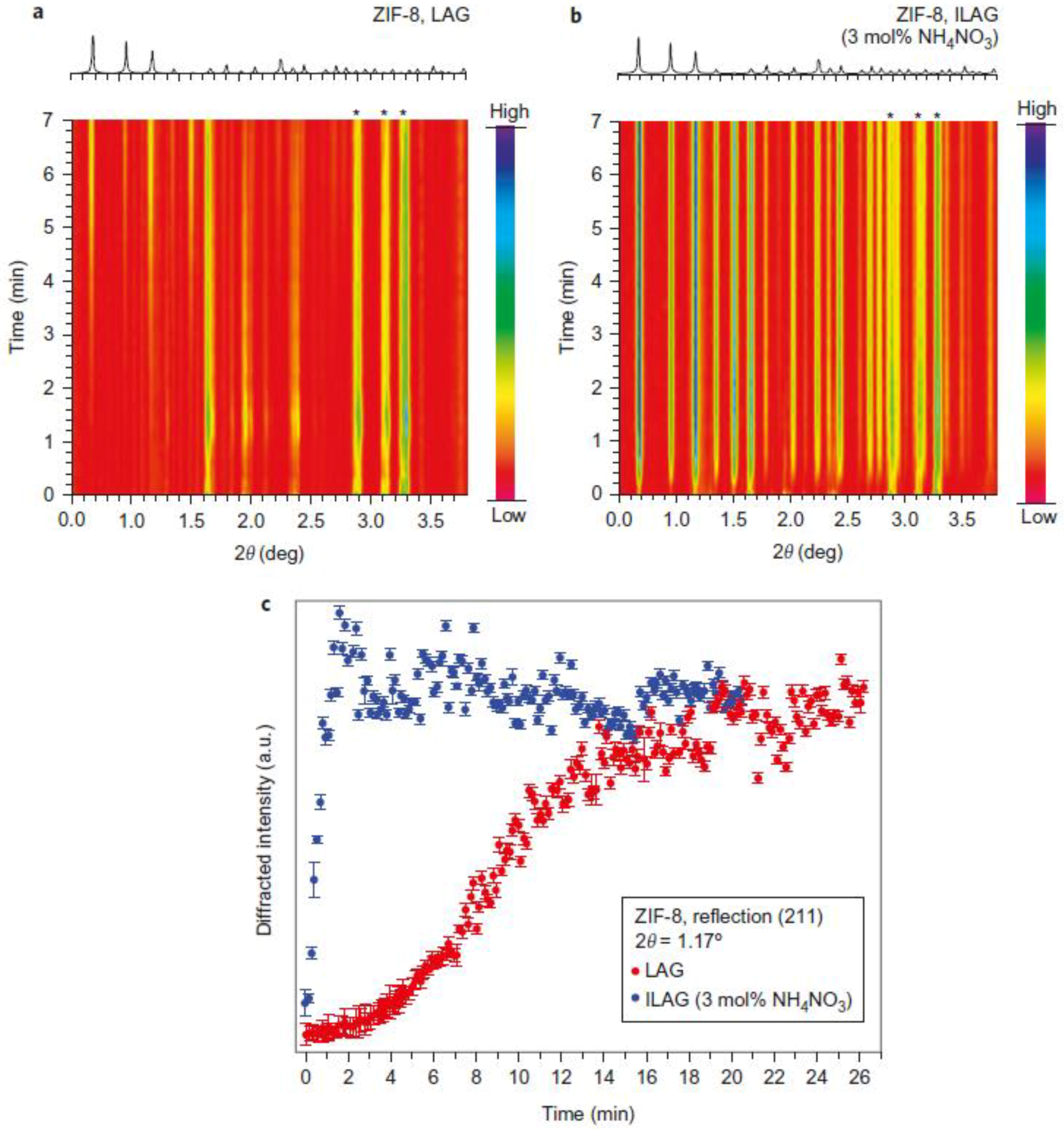
X-ray powder diffraction: XRD is a powerful tool to monitor changes of crystal structure as well as of microstructure (variation of crystallite size, strain, defects etc.). The formation of amorphous phases can be monitored and phase quantification by Rietveld refinement is feasible. However, this method requires high energy X-ray (synchrotron) radiation and thorough modification of the milling vessel to allow the X-ray beam to pass through the jar. Not all jar material is suitable for mechanochemical reactions of hard materials because the energy input may be negatively affected by, say, too ‘soft’ jar materials. Conventional X-ray powder diffraction is sensitive to crystalline materials and their transformations but is unable to analyze atomic structures on a local or molecular state, for example in amorphous materials, gas phases, or liquids.
(d)
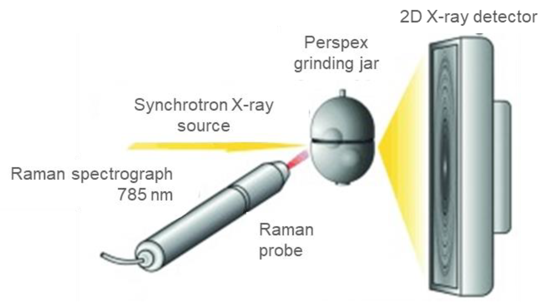
Raman spectroscopy: coupling a laser beam into a milling vessel can bridge this gap. Raman spectroscopy requires the use of translucent polymer jars. The combination of Raman and fast synchrotron X-ray diffraction experiments enables data collection on the same time scale to obtain information on a mechanochemical reaction.
(e)
NMR spectroscopy: the application of complementary methods such as NMR spectroscopy has shown that there exist further options for coupling analytical methods with the mechanochemical process.
(f)
Online gas analysis: coupling of the milling vessel with a gas dosing and a gas detection system based on IR or mass spectrometry finally enables monitoring of structural changes during mechanocatalysis simultaneously with the operando quantification of gaseous reaction products [34].
The performance of in situ/operando characterization, in general, generates a large number of data sets within a short time. The generation of ‘big data’ requires the development of new methodologies and approaches for their analysis. Handling of such large amounts of data and extraction of meaningful and reliable information can be achieved, for example, by machine learning. However, this interesting topic is far beyond the scope of this review article and must be explored in further detail elsewhere.

3. Conclusions

In this review article, the milestones in the implementation of characterization techniques for the in situ/operando studies of mechanochemical reactions are summarized.
Even though mechanochemical reactions have been used since the Neolithic, it is only recently that the technical possibilities have been opened up to perform analysis during the grinding process. Since most of the mechanochemical reactions are performed on solids, solid-state characterization techniques such as high-energy X-ray diffraction or Raman spectroscopy are suitable experimental probes. However, looking into a milling vessel is very challenging since the milling conditions (shaking) and the sample environment (vessel) can limit analytics. Modifications of mill setup and vessel material or design can lead to a change of the energy input required for a successful mechanochemical reaction of hard materials. Therefore, equipment suitable for the investigation of soft materials such as MOFS or co-crystals may not be suitable for in situ studies of hard materials.
The papers on in situ characterization during mechanochemical reactions published over the last 10 years show how powerful these techniques became from following the formation of a material to the analysis of kinetic properties, to the detailed study of chemical or physical properties. The development of additional in situ tools complementary to X-ray and Raman spectroscopy is certainly not at its end. In the future, many new tools will be available for studying mechanochemical reactions as a whole. Information obtained from these studies will further advance mechanochemistry both in academic research and industrial applications.

Funding

This research received no external funding.

Institutional Review Board Statement

Not applicable.

Data Availability Statement

Not applicable.

Acknowledgments

Hilke Petersen and Wolfgang Schmidt (MPI Kohlenforschung) are acknowledged for critical reading of the manuscript.

Conflicts of Interest

The author declares no conflict of interest.

References

  1. IUPAC. Compendium of Chemical Terminology. In The “Gold Book”, 2nd ed.; McNaught, A.D., Wilkinson, A., Eds.; Blackwell Scientific Publications: Oxford, UK, 1997; ISBN 0-9678550-9-8. [Google Scholar] [CrossRef]
  2. McCormick, P.G.; Froes, F.H. The fundamentals of mechanochemical processing. JOM 1998, 50, 61–65. [Google Scholar] [CrossRef]
  3. Takacs, L. Quicksilver from cinnabar: The first documented mechanochemical reaction? JOM 2000, 52, 12–13. [Google Scholar] [CrossRef]
  4. Lea, M.C., IV. Disruption of the silver haloid molecule by mechanical force. Lond. Edinb. Dublin Philos. Mag. J. Sci. 1892, 34, 46–50. [Google Scholar] [CrossRef] [Green Version]
  5. Ling, A.R.; Baker, J.L. XCVI—Halogen derivatives of quinone. Part III. Derivatives of quinhydrone. J. Chem. Soc. Trans. 1893, 63, 1314–1327. [Google Scholar] [CrossRef]
  6. Ostwald, W. Die Chemische Literatur und die Organisation der Wissenschaft. In Handbuch der Allgemeinen Chemie; Ostwald, W., Drucker, C., Eds.; Akademische Verlagsgesellschaft mbH: Leipzig, Germany, 1919; pp. 70–77. [Google Scholar]
  7. Baláž, P.; Dutková, E. Fine milling in applied mechanochemistry. Miner. Eng. 2009, 22, 681–694. [Google Scholar] [CrossRef]
  8. Gomollón-Bel, F. Ten Chemical Innovations That Will Change Our World: IUPAC Identifies Emerging Technologies in Chemistry with Potential to Make Our Planet More Sustainable. Chem. Int. 2019, 41, 12–17. [Google Scholar] [CrossRef]
  9. Boldyrev, V.V.; Tkácová, K. Mechanochemistry of Solids: Past, Present, and Prospects. J. Mater. Synth. Process. 2000, 8, 121–132. [Google Scholar] [CrossRef]
  10. Baláž, P. Mechanochemistry in Minerals Engineering. In Mechanochemistry in Nanoscience and Minerals Engineering; Springer: Berlin/Heidelberg, Germany, 2008; pp. 257–296. [Google Scholar]
  11. Boldyrev, V.V. Mechanochemistry and mechanical activation of solids. Uspekhi Khimii 2006, 75, 203–216. [Google Scholar]
  12. James, S.L.; Adams, C.J.; Bolm, C.; Braga, D.; Collier, P.; Friščić, T.; Grepioni, F.; Harris, K.D.M.; Hyett, G.; Jones, W.; et al. Mechanochemistry: Opportunities for New and Cleaner Synthesis. Chem. Soc. Rev. 2011, 41, 413–447. [Google Scholar] [CrossRef] [PubMed] [Green Version]
  13. Takacs, L. The historical development of mechanochemistry. Chem. Soc. Rev. 2013, 42, 7649–7659. [Google Scholar] [CrossRef]
  14. Baláž, P.; Achimovičová, M.; Baláž, M.; Billik, P.; Cherkezova-Zheleva, Z.; Criado, J.M.; Delogu, F.; Dutková, E.; Gaffet, E.; Gotor, F.J.; et al. Hallmarks of mechanochemistry: From nanoparticles to technology. Chem. Soc. Rev. 2013, 42, 7571–7637. [Google Scholar] [CrossRef] [PubMed] [Green Version]
  15. Lapshin, O.V.; Lapshin, O.V.; Boldyreva, E.V.; Boldyrev, V.V. Role of Mixing and Milling in Mechanochemical Synthesis (Review). Russ. J. Inorg. Chem. 2021, 66, 433–453. [Google Scholar] [CrossRef]
  16. Michalchuk, A.A.L.; Boldyreva, E.V.; Belenguer, A.M.; Emmerling, F.; Boldyrev, V.V. Tribochemistry, Mechanical Alloying, Mechanochemistry: What Is in a Name? Front. Chem. 2021, 9, 685789. [Google Scholar] [CrossRef] [PubMed]
  17. Boldyreva, E. Mechanochemistry of inorganic and organic systems: What is similar, what is different? Chem. Soc. Rev. 2013, 42, 7719–7738. [Google Scholar] [CrossRef] [PubMed]
  18. Do, J.-L.; Friščić, T. Mechanochemistry: A Force of Synthesis. ACS Cent. Sci. 2017, 3, 13–19. [Google Scholar] [CrossRef] [Green Version]
  19. Huot, J.; Ravnsbæk, D.B.; Zhang, J.; Cuevas, F.; Latroche, M.; Jensen, T.R. Mechanochemical synthesis of hydrogen storage materials. Prog. Mater. Sci. 2013, 58, 30–75. [Google Scholar] [CrossRef]
  20. Baláž, M.; Zorkovská, A.; Blazquez, J.S.; Daneu, N.; Baláž, P. Mechanochemistry of copper sulphides: Phase interchanges during milling. J. Mater. Sci. 2017, 52, 11947–11961. [Google Scholar] [CrossRef]
  21. Mamatha, M.; Bogdanović, B.; Felderhoff, M.; Pommerin, A.; Schmidt, W.; Schüth, F.; Weidenthaler, C. Mechanochemical preparation and investigation of properties of magnesium, calcium and lithium–magnesium alanates. J. Alloys Compd. 2006, 407, 78–86. [Google Scholar] [CrossRef]
  22. Mi, G.M.; Saito, F. Mechanochemical Polymorphic Transformation of Photocatalyst Material TiO2 and Its Dependence on the Milling Operation. In Advanced Material Science and Technology, Pts 1 and 2; Tan, Y., Ju, D.Y., Eds.; Trans Tech Publications Ltd.: Freienbach, Switzerland, 2011; Volume 675–677, pp. 283–286. [Google Scholar]
  23. Rounaghi, S.A.; Eshghi, H.; Scudino, S.; Vyalikh, A.; Vanpoucke, D.E.P.; Gruner, W.; Oswald, S.; Rashid, A.R.K.; Khoshkhoo, M.S.; Scheler, U.; et al. Mechanochemical route to the synthesis of nanostructured Aluminium nitride. Sci. Rep. 2016, 6, 33375. [Google Scholar] [CrossRef] [Green Version]
  24. Fan, G.J.; Guo, F.Q.; Hu, Z.Q.; Quan, M.X.; Lu, K. Amorphization of selenium induced by high-energy ball milling. Phys. Rev. B 1997, 55, 11010–11013. [Google Scholar] [CrossRef] [Green Version]
  25. Ogino, Y.; Murayama, S.; Yamasaki, T. Influence of milling atmosphere on amorphization of chromium and Cr-Cu powders by ball milling. J. Less Common Met. 1991, 168, 221–235. [Google Scholar] [CrossRef]
  26. Jacobsen, C.J.H.; Zhu, J.J.; Lindeløv, H.; Jiang, J.Z. Synthesis of ternary nitrides by mechanochemical alloying. J. Mater. Chem. 2002, 12, 3113–3116. [Google Scholar] [CrossRef]
  27. Chen, Y.; Williams, J.S. Competitive gas-solid reactions realized by ball milling of Zr in ammonia gas. J. Mater. Res. 1996, 11, 1500–1506. [Google Scholar] [CrossRef]
  28. Ogino, Y.; Yamasaki, T.; Miki, M.; Atsumi, N.; Yoshioka, K. Synthesis of TiN and (Ti, Al)N powders by mechanical alloying in nitrogen gas. Scr. Met. Mater. 1993, 28, 967–971. [Google Scholar] [CrossRef]
  29. Schwarz, R.; Petrich, R.; Saw, C. The synthesis of amorphous Ni-Ti alloy powders by mechanical alloying. J. Non-Cryst. Solids 1985, 76, 281–302. [Google Scholar] [CrossRef]
  30. Hatchard, T.D.; Genkin, A.; Obrovac, M.N. Rapid mechanochemical synthesis of amorphous alloys. AIP Adv. 2017, 7, 045201. [Google Scholar] [CrossRef] [Green Version]
  31. Yoshimoto, S.; Ohashi, F.; Ohnishi, Y.; Nonami, T. Synthesis of polyaniline–montmorillonite nanocomposites by the mechanochemical intercalation method. Synth. Met. 2004, 145, 265–270. [Google Scholar] [CrossRef]
  32. Qu, J.; Zhang, Q.; Li, X.; He, X.; Song, S. Mechanochemical approaches to synthesize layered double hydroxides: A review. Appl. Clay Sci. 2016, 119, 185–192. [Google Scholar] [CrossRef]
  33. Buyanov, R.A.; Molchanov, V.V.; Boldyrev, V.V. Mechanochemical activation as a tool of increasing catalytic activity. Catal. Today 2009, 144, 212–218. [Google Scholar] [CrossRef]
  34. Immohr, S.; Felderhoff, M.; Weidenthaler, C.; Schüth, F. An Orders-of-Magnitude Increase in the Rate of the Solid-Catalyzed CO Oxidation by In Situ Ball Milling. Angew. Chem. Int. Ed. 2013, 52, 12688–12691. [Google Scholar] [CrossRef]
  35. Schreyer, H.; Immohr, S.; Schüth, F. Oscillatory combustion of propene during in situ mechanical activation of solid catalysts. J. Mater. Sci. 2017, 52, 12021–12030. [Google Scholar] [CrossRef] [Green Version]
  36. Porcheddu, A.; Colacino, E.; De Luca, L.; Delogu, F. Metal-Mediated and Metal-Catalyzed Reactions under Mechanochemical Conditions. ACS Catal. 2020, 10, 8344–8394. [Google Scholar] [CrossRef]
  37. Tan, D.; García, F. Main group mechanochemistry: From curiosity to established protocols. Chem. Soc. Rev. 2019, 48, 2274–2292. [Google Scholar] [CrossRef] [Green Version]
  38. Boldyrev, V.V.; Avvakumov, E.G. Mechanochemistry of Inorganic Solids. Russ. Chem. Rev. 1971, 40, 847–859. [Google Scholar] [CrossRef]
  39. Topsøe, H. Developments in operando studies and in situ characterization of heterogeneous catalysts. J. Catal. 2003, 216, 155–164. [Google Scholar] [CrossRef]
  40. Liu, D.; Shadike, Z.; Lin, R.; Qian, K.; Li, H.; Li, K.; Wang, S.; Yu, Q.; Liu, M.; Ganapathy, S.; et al. Review of Recent Development of In Situ/Operando Characterization Techniques for Lithium Battery Research. Adv. Mater. 2019, 31, e1806620. [Google Scholar] [CrossRef]
  41. Weidenthaler, C. 1. Weidenthaler, C. 1 In situ tools for the exploration of structure–property relationships. In Crystallography in Materials Science: From Structure-Property Relationships to Engineering; Susan, S., Claudia, W., Eds.; De Gruyter: Berlin, Germany, 2021; pp. 1–54. [Google Scholar]
  42. von Colbe, J.M.B.; Felderhoff, M.; Bogdanović, B.; Schüth, F.; Weidenthaler, C. One-step direct synthesis of a Ti-doped sodium alanate hydrogen storage material. Chem. Commun. 2005, 36, 4732–4734. [Google Scholar] [CrossRef]
  43. Takacs, L. Self-sustaining reactions induced by ball milling. Prog. Mater. Sci. 2002, 47, 355–414. [Google Scholar] [CrossRef]
  44. Tschakarov, C.; Gospodinov, G.; Bontschev, Z. Über den Mechanismus der mechanochemischen Synthese anorganischer Verbindungen. J. Solid State Chem. 1982, 41, 244–252. [Google Scholar] [CrossRef]
  45. Tschakarov, C.; Rusanov, V.; Gospodinov, G. Untersuchungen zum Mechanismus der Mechanochemischen Synthese von Verbindungen aus dem System SnS mit Hilfe des Mössbauer-Effektes. J. Solid State Chem. 1985, 59, 265–271. [Google Scholar] [CrossRef]
  46. Friščić, T.; Halasz, I.; Beldon, P.J.; Belenguer, A.M.; Adams, F.; Kimber, S.; Honkimäki, V.; Dinnebier, R.E. Real-time and in situ monitoring of mechanochemical milling reactions. Nat. Chem. 2012, 5, 66–73. [Google Scholar] [CrossRef] [PubMed]
  47. Halasz, I.; Kimber, S.; Beldon, P.J.; Belenguer, A.M.; Adams, F.; Honkimäki, V.; Nightingale, R.C.; Dinnebier, R.E.; Friščić, T. In situ and real-time monitoring of mechanochemical milling reactions using synchrotron X-ray diffraction. Nat. Protoc. 2013, 8, 1718–1729. [Google Scholar] [CrossRef] [PubMed]
  48. Halasz, I.; Puškarić, A.; Kimber, S.A.J.; Beldon, P.J.; Belenguer, A.M.; Adams, F.; Honkimäki, V.; Dinnebier, R.E.; Patel, B.; Jones, W.; et al. Real-Time In Situ Powder X-ray Diffraction Monitoring of Mechanochemical Synthesis of Pharmaceutical Cocrystals. Angew. Chem. Int. Ed. 2013, 52, 11538–11541. [Google Scholar] [CrossRef] [PubMed]
  49. Halasz, I.; Friščić, T.; Kimber, S.A.J.; Užarević, K.; Puškarić, A.; Mottillo, C.; Julien, P.; Štrukil, V.; Honkimäki, V.; Dinnebier, R.E. Quantitative in situ and real-time monitoring of mechanochemical reactions. Faraday Discuss. 2014, 170, 203–221. [Google Scholar] [CrossRef] [PubMed]
  50. Užarević, K.; Štrukil, V.; Mottillo, C.; Julien, P.A.; Puškarić, A.; Friščić, T.; Halasz, I. Exploring the Effect of Temperature on a Mechanochemical Reaction by in Situ Synchrotron Powder X-ray Diffraction. Cryst. Growth Des. 2016, 16, 2342–2347. [Google Scholar] [CrossRef]
  51. Biliškov, N.; Borgschulte, A.; Užarević, K.; Halasz, I.; Lukin, S.; Milošević, S.; Milanović, I.; Novaković, J.G. In-Situ and Real-time Monitoring of Mechanochemical Preparation of Li2Mg(NH2BH3)4 and Na2Mg(NH2BH3)4 and Their Thermal Dehydrogenation. Chem.—Eur. J. 2017, 23, 16274–16282. [Google Scholar] [CrossRef] [Green Version]
  52. Tumanov, N.; Ban, V.; Poulain, A.; Filinchuk, Y. 3D-printed jars for ball-milling experiments monitoredin situby X-ray powder diffraction. J. Appl. Crystallogr. 2017, 50, 994–999. [Google Scholar] [CrossRef]
  53. Lampronti, G.I.; Michalchuk, A.A.L.; Mazzeo, P.P.; Belenguer, A.M.; Sanders, J.K.M.; Bacchi, A.; Emmerling, F. Changing the game of time resolved X-ray diffraction on the mechanochemistry playground by downsizing. Nat. Commun. 2021, 12, 6134. [Google Scholar] [CrossRef]
  54. Ban, V.; Sadikin, Y.; Lange, M.; Tumanov, N.; Filinchuk, Y.; Černý, R.; Casati, N. Innovative In Situ Ball Mill for X-ray Diffraction. Anal. Chem. 2017, 89, 13176–13181. [Google Scholar] [CrossRef]
  55. Batzdorf, M.S.L.; Fischer, D.-C.F.; Wilke, D.-C.M.; Wenzel, D.-I.K.-J.; Emmerling, F. Direct In Situ Investigation of Milling Reactions Using Combined X-ray Diffraction and Raman Spectroscopy. Angew. Chem. Int. Ed. 2015, 54, 1799–1802. [Google Scholar] [CrossRef]
  56. Amrute, A.P.; Łodziana, Z.; Schreyer, H.; Weidenthaler, C.; Schüth, F. High-surface-area corundum by mechanochemically induced phase transformation of boehmite. Science 2019, 366, 485–489. [Google Scholar] [CrossRef]
  57. Rathmann, T.; Petersen, H.; Reichle, S.; Schmidt, W.; Amrute, A.P.; Etter, M.; Weidenthaler, C. In situ synchrotron X-ray diffraction studies monitoring mechanochemical reactions of hard materials: Challenges and limitations. Rev. Sci. Instrum. 2021, 92, 114102. [Google Scholar] [CrossRef] [PubMed]
  58. Petersen, H.; Reichle, S.; Leiting, S.; Losch, P.; Kersten, W.; Rathmann, T.; Tseng, J.; Etter, M.; Schmidt, W.; Weidenthaler, C. In Situ Synchrotron X-ray Diffraction Studies of the Mechanochemical Synthesis of ZnS from Its Elements. Chem.—Eur. J. 2021, 27, 12451–12452. [Google Scholar] [CrossRef] [PubMed]
  59. Baláž, P.; Aláčová, A.; Achimovičová, M.; Ficeriová, J.; Godočíková, E. Mechanochemistry in hydrometallurgy of sulphide minerals. Hydrometallurgy 2005, 77, 9–17. [Google Scholar] [CrossRef]
  60. Boldyreva, E. Defogging the view through a milling jar. Nat. Chem. 2022, 14, 10–12. [Google Scholar] [CrossRef]
  61. Lin, H.-L.; Zhang, G.-C.; Hsu, P.-C.; Lin, S.-Y. A portable fiber-optic Raman analyzer for fast real-time screening and identifying cocrystal formation of drug-coformer via grinding process. Microchem. J. 2013, 110, 15–20. [Google Scholar] [CrossRef]
  62. Gracin, D.; Štrukil, V.; Friščić, T.; Halasz, I.; Užarević, K. Laboratory Real-Time and In Situ Monitoring of Mechanochemical Milling Reactions by Raman Spectroscopy. Angew. Chem. Int. Ed. 2014, 53, 6193–6197. [Google Scholar] [CrossRef] [Green Version]
  63. Kulla, H.; Wilke, M.; Fischer, F.; Röllig, M.; Maierhofer, C.; Emmerling, F. Warming up for mechanosynthesis—Temperature development in ball mills during synthesis. Chem. Commun. 2017, 53, 1664–1667. [Google Scholar] [CrossRef]
  64. Schiffmann, J.G.; Emmerling, F.; Martins, I.C.; Van Wüllen, L. In-situ reaction monitoring of a mechanochemical ball mill reaction with solid state NMR. Solid State Nucl. Magn. Reson. 2020, 109, 101687. [Google Scholar] [CrossRef]
Figure 1. (a) Positioning of a modified Retsch MM200 mill on a motorized, movable x-,y-,z-stage at the ESRF beamline ID15B with modified arms (red arrow). (b) Modified arms position the polymer vessels (red arrow) in the X-ray beam. Reprinted with permission from [48]. Copyright 2013, John Wiley and Sons.
Crystals 12 00345 g001
Figure 2. Time-resolved in situ XRD patterns monitoring the mechanochemical synthesis of ZIF-8 framework: (a) synthesis using LAG with DMF, (b) synthesis using ILAG with NH4NO3. (c) Time-dependent intensity changes of the strongest reflection of ZIF-8 synthesized in the LAG (red) and ILAG (blue) reactions. Reprinted with permission from [46]. Copyright 2012, Springer Nature.
Crystals 12 00345 g002
Figure 4. In situ X-ray synchrotron powder patterns of empty vessels show different background contributions depending on the material and wall thickness. Type 0: PMMA, Type 1–4: PLA. Minor diffraction peaks originate from a colorant in the PLA vessels. Reprinted with permission of [52]. Copyright 2017, International Union Of Crystallography.
Crystals 12 00345 g004
Figure 5. (a) Two half-shells forming the milling jars with the perforated outer part, (b) the milling jars with a Kapton film protecting the probing area, and (c) scheme of the milling jar showing the movement of the jar on the mill. Adapted with permission from [54]. Copyright 2017, American Chemical Society.
Crystals 12 00345 g005
Figure 6. In situ powder pattern measured at ESRF ID15 beamline (Grenoble, France) with a shaker mill (red top curve) compared to the new mill design used at SLS MS beamline (Villigen, Switzerland) (blue bottom curve) for the reaction between LiBH4 and CsBH4. Reprinted with permission from [54]. Copyright 2017, American Chemical Society.
Crystals 12 00345 g006
Figure 7. (a) 10 mL Perspex grinding vessels stationary and vibrating, (b) measured XRD images recorded every 30 s. Reprinted with permission from [55]. Copyright 2014, John Wiley and Sons.
Crystals 12 00345 g007
Figure 8. (a) IR spectra of the gas phase formed inside the milling vessels obtained in situ during milling with one stainless-steel ball of 15 mm diameter and a PMMA window, (b) disassembled milling vessel with the labeled single components including the PMMA window and the inner protecting steel inset. Reprinted with permission of [57]. Copyright 2021, AIP Publishing.
Crystals 12 00345 g008
Figure 9. Laboratory Raman spectroscopy experiments for in situ studies of mechanochemical transformations of coordination polymers, organic materials, and liquid additives. Reprinted with permission from [62]. Copyright 2014, John Wiley and Sons.
Crystals 12 00345 g009
Figure 10. Schematic diagram of the experimental setup for simultaneous Raman and XRD experiments during mechanochemical synthesis. Reprinted with permission from [55]. Copyright 2014, John Wiley and Sons.
Crystals 12 00345 g010
Figure 11. (a) In situ synchrotron diffraction patterns monitored during the synthesis of the metal–organic framework (H2Im)[Bi(1,4-bdc)2], (b) in situ Raman spectra. The first Raman spectrum (gray) belongs to the empty Perspex jar, yellow: reactants, blue: intermediate phase and terephthalic acid, purple: product 2 and terephthalic acid, red: product. Reprinted with permission from [54]. Copyright 2014, John Wiley and Sons.
Crystals 12 00345 g011
Figure 12. (a) Combination of a ball mill equipped with polymer milling vessels with a Raman laser and an IR camera. (b) From Raman spectroscopy, structural information is obtained, and at the same time (c) temperature changes can be followed over time. Reprinted with permission from [63]. Copyright 2017, Royal Society of Chemistry.
Crystals 12 00345 g012
Figure 13. (a) Temperature distribution in the vessel measured during the formation of tb:ox co-crystals. (b) Time-dependent temperature change inside the milling jar during the reaction (black line) compared to reference SiO2 powder milled under the same conditions (grey line). Orange: start of the amorphization, blue region: reaction period. The hydrogen bonding system in the crystal structures of the reactants and the co-crystal is shown as insets. Reprinted with permission from [63]. Copyright 2017, Royal Society of Chemistry.
Crystals 12 00345 g013
Publisher’s Note: MDPI stays neutral with regard to jurisdictional claims in published maps and institutional affiliations.

