Article

Picosecond Pulsed-Periodic High-Peak Power Nd:YAG Laser Operationally Controlled by KTP-Based Pockels Cell

1
Faculty of Physics, M. V. Lomonosov Moscow State University, Leninskie Gory 1, 119991 Moscow, Russia
2
S. I. Vavilov State Optical Institute, Kadetskaya Line 5, 195000 St. Petersburg, Russia
3
Applied Physics Department, Novosibirsk State University, Pirogova Str., 630090 Novosibirsk, Russia
4
D. I. Mendeleyev Institute of Metrology, Moskovsky Ave. 19, 190005 St. Petersburg, Russia
*
Author to whom correspondence should be addressed.
Crystals 2022, 12(3), 368; https://doi.org/10.3390/cryst12030368
Submission received: 31 January 2022 / Revised: 5 March 2022 / Accepted: 7 March 2022 / Published: 9 March 2022

Abstract

:
Electro-optical modulators are effectively used for ultrafast pulse lasers operation control. The scheme of picosecond pulse-periodic high-peak-power Nd:YAG lasers is composed of an active-passive mode-locked and negative feedback-controlled master oscillator and regenerative amplifier based on common end-diode-pumped Nd:YAG crystal. A double-crystal thermally compensated Pockels cell based on KTP crystals of the Y-cut direction is employed as a key control element. The cell was assembled using a pair of equal-length crystals grown according to high-resistivity technology. The scheme provides output pulses with energy up to 1.6 mJ, a duration of 25 ps at repetition rates tunable from 0 to 200 Hz. The laser operation stages are analyzed in detail. The scheme looks attractive and promising for developing advanced ultrafast laser systems with higher repetition rates, peak and, accordingly, average power levels. The Pockels cell based on KTP crystals expands the line of available fast electro-optical control elements, along with the previously used RTP ones. The factors limiting laser pulse energy and repetition rate are discussed. Parasitic nonlinear conversion in the crystals of the Pockels cell along the axis may play an essential role. The results of comparative measurements of the second and third harmonics made with the Pockels cells based on KTP and RTP crystals of both X-cut and Y-cut directions are presented. The minimum second and third harmonics efficiency levels observed in the Y-cut Pockels cells of the KTP crystal seem to be their important advantage.

1. Introduction

In recent years, high-peak-power picosecond lasers have been used in a variety of scientific and technological applications, such as time-resolved nonlinear laser spectroscopy [1,2,3], laser ablation and micromachining [4,5], picosecond optical parametric amplifiers pumping [6], photo-guns equipped in electron accelerator injectors [7,8], precise satellite [9,10] and lunar [11,12] laser ranging, laser driving wide-band high-power semiconductor switches [13,14], coherent anti-Stokes Raman microscopy [15], two-photon bioimaging [16], aesthetic cosmetology and dermatology [17,18] and clinical surgery [19,20]. Then, practical and reliable, highly stable and compact picosecond laser schemes providing single pulse energy of mJ and multi-mJ levels operating at different repetition rates, typically within kHz, are widely required.
Compared to femtosecond lasers, picosecond ones proved their practical suitability due to simpler amplification schemes and power scaling [21,22]. Different schemes of operational control based on electro-optical modulators, i.e., Pockels cell (PC) plus polarizer, were utilized for picosecond pulse generation since the early laser era [23]. Active mode-locking (AML) allows high-peak-power ultra-short pulses synchronized with external electronic signals to be obtained. The periodic modulation of cavity losses in order to obtain picosecond pulses can also be realized by means of acousto-optical modulators [21]. AML usually concedes to passive mode-locking (PML) in pulse shortening and realization simplicity but definitely has some advantages regarding output radiation stability and timing jitter control [24,25].
Needs for lasers with better energy and temporal stability, effective output picosecond pulses shortening stimulated development of combined schemes based on active-passive mode-locking, cavity Q-factor control and negative feedback (NFB). Different approaches involving passive mode-locking [26,27,28], active (electro-optical) negative feedback [29,30] and cavity Q-factor control have been proposed since the 1980s and were used to achieve a more stable generation of picosecond pulses. At the same time, a combined scheme of active-passive mode-locking and electro-optical NFB was proposed [31,32]. This scheme combined advantages of both active and passive mode-locking in points of: (1) principal ability to control a generated pulse phase within the round trip time and (2) maximum shortening of pulse duration, with the ability to significantly improve pulse-to-pulse reproducibility by means of applying amplified fast photodiode voltage with the corresponding polarity to PCs to realize NFB.
A reasonable way to obtain milli-Joule single pulse energy levels, starting from pico/nano/micro-Joule seed pulses, is to utilize a regenerative amplifier scheme. It is a well-established approach for the generation of stable, high-peak-power ultra-short laser pulses [33]. In recent decades, significant progress has also been made in the development of diode laser pumping systems, which provide high efficiency, improved stability, reduced thermal load on active laser crystal [21,34] and are ideally suited, in particular, for Nd or Yb-doped media, widely used for picosecond pulse operation [21].
The invention and development of nonlinear absorbers of SESAM type (Semiconductor Saturable Absorber Mirror) [35] contributed essentially to the formation of typical approaches to picosecond lasers based on PML and prospects for the development of such lasers [36,37]. At the same time, the obvious advantage of AML is lower optical jitter that can be made significantly smaller in comparison with the cavity round trip time, and, respectively, the principal ability to synchronize optical pulse with accuracy within pulse duration to an external electronic signal. In the combined active-passive mode-locked and NFB-controlled scheme, optical jitter with respect to the external synchronizing pulse was as low as 40 ps [38]. Even better results can be principally expected using phase modulation [39].
It can be noted that AML is much more often realized using acousto-optic modulators [21], which are usually characterized by a high damage threshold, reliability and universality [40]. However, there is a significant inconvenience associated with the micron accuracy adjustment of the cavity length to the resonant frequency of the modulator quartz crystal. This definitely limits the opportunities for cavity scheme corrections and mode structure optimization. At the same time, AML resonant frequency in the case of PC usage depends on electric circuit characteristics and can be varied simply in a very wide range by adjusting, for example, the value of variable inductance. Moreover, an acoustic standing wave pattern in acousto-optic modulators is established during a fraction of milliseconds after applying a sinusoidal voltage to the modulator, while the electro-optical modulator’s response is essentially faster. Let us also mention the general progress in the development of modern phase and amplitude PCs [41,42], as well as high-speed control electronics [43,44].
Summing up, one could state that utilizing PCs as key operational control elements in efficient and compact picosecond lasers comprising active-passive mode-locked and NFB-controlled master oscillator and the subsequent regenerative amplifier looks attractive and promising.
Crystals of the KTP family (KTP and RTP are widely used) meet the basic requirements for advanced electro-optical materials and are characterized by a unique combination of physical parameters that are needed for highly effective electro-optical modulation performance [45]: low absorptivity at the laser wavelength, high damage threshold, low piezoelectric coupling of the electric field to acoustics and relatively large electro-optical coefficients. In fact, they outperform most other electro-optical crystals by the combination of their characteristics [46,47,48,49,50,51].
In KTP and RTP crystals, the electro-optical coefficients have the largest value in the case of light propagation along the X or Y crystal axes. PC can operate in this case on transverse effect in crystals of X-cut or Y-cut directions. The electrical field is directed along the crystal’s Z-axis. The radiation propagates not along the optical axis and, therefore, crystal anisotropy plays an essential role. For compensation of natural crystal birefringence and of its temperature dependence, double-crystal schemes with the angle between the crystals Z-axis of 90° are usually utilized. The directions of the initial radiation polarization are +45° or −45° relative to the Z-axis (Figure 1). Regarding the KTP and RTP-based PCs (KTP PC and RTP PC), one can then classify the cases of KTP/RTP PC of X/Y-cut directions (X/Y-cut KTP/RTP PC). The double crystal scheme providing thermal stabilization was applied back in the 1960s for television digital channels modulation with the use of KDP crystals with the difference that in KDP crystals, the beam propagates along the optical axis [52].
In our earlier work [53], we developed the scheme of a pulsed-periodic picosecond laser comprising an active-passive mode-locked and NFB-controlled picosecond Nd:YAG master oscillator combined with a regenerative amplifier on the same active crystal pumped with a fiber-coupled qcw laser diode array module. The pulsed (or qcw) pumping regime provides a minimal thermal load on the active laser crystal. The regenerative amplifier scheme allows the shortest way to obtain pulses of high-peak-power and of high beam quality starting from the sub-microjoule level at master oscillator output to be used. The key operation control element was the double-crystal 3 × 3 × 10 mm3 RTP PC (it was X-cut RTP PC) assembled in accordance with the thermo-compensated scheme, which was used simultaneously for AML, NFB control and also for Q-factor control by means of the offset voltage application. Passive mode-locking was realized using SESAM. The scheme provided single pulse generation with a width of 25 ps. Additionally, two identical RTP PCs were utilized for switching picosecond pulse from the master oscillator cavity to the regenerative amplifier cavity and then for cavity dumping. The maximum output single pulse energy was limited mainly due to optical damage in the switcher and dumper RTP PCs crystals. The level of 0.3 mJ single pulse energy was considered as the maximum, which is acceptable for long-term laser operation without damage. The applied scheme with the dual use of the active crystal in both oscillator and regenerative amplifier cavities makes the scheme compact and practical. It should be noted that the laser operation was accompanied by well-visible second harmonic (SH) radiation coming from the switcher and dumper RTP PCs crystals. With peak generation intensities of 109 W/cm2 level, this looked quite natural and was not specially discussed, and there were no obvious direct observations connecting the PC crystal damage with the SH effect. However, the appearing instabilities of the SH signal could serve as a visual indicator of the approaching damage. The SH generation level within the RTP PC, providing AML and NFB, was also noticeable with essentially lower intensity according to lower peak power at the master oscillator stage. Afterward, the set of three RTP PCs was replaced with the new one selected from the new delivery batch of Y-cut RTP PCs, which showed a lower SH level. However, the efforts to raise output power using higher pump power regularly ended in the breakdown of the switcher and dumper crystals. Then, the double-crystal RTP PCs of the switcher and dumper were replaced with single-crystal DKDP ones, while the Y-cut RTP PC for AML and NFB was continued to be used. This provided an increase in single output pulse energy up to 1.5 mJ at 25 ps pulse width with Nd:YAG and up to 2.0 mJ at 17 ps pulse width with Nd:YLF at repetition rates below 100 and 50 Hz, respectively [54,55].
An increase of the repetition rate at high enough pump peak power is associated with a growth of the thermal load on the active laser crystal and with a gradual increase in the magnitude of the thermal lens, which has an inherent aberrational part in the end-pump geometry. This results in the cavity leaving its stability zone, which can be compensated to a certain extent by using the appropriate lens or spherical mirror. However, with the increase of average pump power, the aberrational part of the thermal lens becomes prevailing [55]. In [56], we adopted an Nd:YAG laser to operate at repetition rates up to 300 Hz. Wherein, the energy of single pulses obtained after regenerative amplification at the highest frequencies was approximately half that at reasonably low ones. The most obvious reason is the greater spending of the stored inverse population during the oscillator stage and, maybe, less effective mode-locking of modes corrupted by aberrations. At a further increase of repetition rate, the lasing shows mode-locking instability and then terminates. Thus, the outlined approach can be considered as quite suitable for obtaining pulses of high-peak power at reasonably low repetition rates while based on a simple and compact laser scheme. At the indicated energies and pulse widths, the peak power density can be 1010 W/cm2 or more. This determines the requirements for the optical quality and stability of key elements and motivates attempts to improve the scheme for better output characteristics. Therefore, a detailed analysis of the generation process is necessary.
Thermo-compensated PC is a key element in the complex dynamics of laser generation under conditions of active-passive mode-locking and negative feedback. High-peak and average power laser radiation circulating in the laser cavity may be accompanied by different nonlinear optical processes. The most visible and obvious one is the SH generation. Then, there are apparent reasons to pay special attention to SH generation in PC crystals. In fact, SH generation along the axis of PC crystals is a parasitic, undesirable effect due to its possible negative consequences: nonlinear absorption increasing within the visible and near-IR wavelength ranges and the grey track formation. This effect was observed in multiple experimental studies [57,58,59,60]. Grey track formation was also reported in KTP crystals under UV radiation [57,61,62], which is similar to the effects induced by SH of the Nd:YAG laser radiation. These processes can induce crystal optical non-uniformity and decrease PC’s contrast. In practice, the inevitable result of the gray track appearance is the gradual degradation of PC crystals during long-term laser operation.
Cascade processes on quadratic nonlinearities involving SH and fundamental radiation [63,64], as well as direct process on cubic nonlinearity [65], may be responsible for third harmonic (TH) generation in RTP and KTP crystals. The TH intensity may be smaller than the SH one, but the absorption of the TH is much higher due to proximity to the UV cutoff wavelength [64] and is on the level of 5–10 cm−1 for KTP crystals [66]. That is why the efficiency of nonlinear processes contributing to UV radiation and their role in the gray track formation deserves careful study. TH generation and stimulated Raman scattering processes peculiar to KTP crystals [67,68] seem to be very important in this regard, and the TH role seems to deserve top priority. It is also natural to assume that absorbed UV (primarily, TH) radiation can be a source of crystal heating at high enough peak power and repetition rates that can lead to the violation of PC crystals’ thermal compensation condition. That is why a significant part of the attention ought to be devoted to the study of TH efficiency in KTP and RTP crystals.
In the present paper, we demonstrate the scheme and operation details of a high-peak-power picosecond Nd:YAG laser built on the basis of a master oscillator/regenerative amplifier approach. The AML and NFB-controlling double crystal PC was made from KTP crystals of the Y-cut direction grown according to the high resistivity technology, preventing electrochromic crystal degradation [49]. The choice of Y-cut KTP PC was dictated by the expected minima of SH and TH generation levels. Special attention was paid to comparative measurements of conversion efficiency of high-peak-power picosecond Nd:YAG fundamental wavelength radiation into both SH (532 nm) and TH (355 nm) in PCs based on KTP and RTP crystals of Y-cut and X-cut directions. It was also examined whether the contrast of the Y-cut KTP PC can be decreased due to the strong absorption of the TH radiation in the cell crystals.

2. Materials and Methods

2.1. KTP Family Crystals for PCs and Second Harmonic Conversion Efficiency

Crystals of the KTP family are positive bi-axial crystals belonging to the mm2 point group of the orthorhombic class symmetry [62]. For these crystals, the relation between the main refractive indices is n x < n y < n z . Beam propagation along the XY plane ( θ = 90°) of such crystals is similar to the beam propagation in a negative uniaxial crystal with n o = n z and n e :
n e = n y 1 + tg 2 φ / 1 + n y / n x 2 tg 2 φ
For the wave polarized perpendicular to the XY plane, the refractive index is equal to n z . For the wave polarized in the XY plane, the refractive index varies from n y to n x with the φ variation from 0° to 90°, where φ is the azimuthal angle between the laser beam and the X-axis. It is n y for X-cut and n x for Y-cut crystals, respectively. For such crystals, SH interaction of Type II: 1064 (o) + 1064 (e) → 532 (e) is allowed. Exact phase-matching conditions for oe-e SH interaction is achieved at θ = 90°, φ s = 23.6° for KTP and at θ = 90°, φ s = 56.3° for RTP (Figure 2), where φ s is the angle of synchronism, θ is the angle between the laser beam and the Z-axis.
In PC crystals, the SH is generated under conditions far from synchronism. Despite this, the SH intensity may become pronounced as the intensity of the fundamental wave reaches the GW/cm2 level (see further Section 2.3).
In the case of the X-cut KTP crystal (Figure 2a), 1064 nm wave electric vector E makes 45° with the Y and Z-axes. The projection of E on the Y-axis represents (o) wave, on the Z-axis (e) wave. Therefore, the phase mismatch of the oe-e SH process in the first X-cut KTP crystal is [63,64]:
Δ x = ω 1 / c n 1 y + ω 1 / c n 1 z 2 ω 1 / c n 2 y = 2 π / λ 1 n 1 y + n 1 z 2 n 2 y ,
where ω 1 and λ 1 denote the frequency and wavelength, respectively, of the fundamental (1064 nm) wave. Principal refractive indexes n are numbered according to fundamental “1” or second harmonic “2” (532 nm) waves.
The second X-cut KTP crystal is rotated on 90° around the X-axis, in this way, the compensation of the crystals birefringence is achieved. This rotation does not change phase-matching conditions for SH generation in the second KTP crystal (2).
In the case of Y-cut KTP crystal, we obtain the analogous expressions for oe-e SH phase mismatch:
Δ y = ω 1 / c n 1 x + ω 1 / c n 1 z 2 ω 1 / c n 2 x = 2 π / λ 1 n 1 y + n 1 z 2 n 2 x ,
The output intensities satisfy the following condition
I x , y L d eff 2 sin ξ x , y / ξ x , y 2
where ξ x , y = L Δ x , y / 2 , L is the crystal length. At θ = 90°, the effective nonlinearity coefficient d eff for the oe-e interaction is expressed as:
d eff = d o e e = d 31 sin 2 φ + d 32 cos 2 φ ,
which gives
d eff = d 32   for   X - cut ,   d eff = d 31   for   Y - cut ,
where d 32 and d 31 are nonlinearity coefficients.
At high enough mismatch values, as in our case, averaging sin ξ 2 gives 1/2. Then the SH intensities ratio for X and Y-cut crystals should be:
I x / I y = Δ y d 32 / Δ x d 31 2
In Table 1, we collect the available data on principal refractive indexes for fundamental and second harmonic wavelengths, corresponding wavenumber phase mismatches and nonlinear coefficients affecting second harmonic intensity generated along the axes of X-cut and Y-cut KTP [68,69,70] and RTP [71,72] crystals. As for RTP crystals, data on the refractive indexes [70] and nonlinear coefficients [72] were extracted from different references.
Presented in Table 1, the data show that estimated values I x / I y demonstrate significant second harmonic intensity prevailing in X-cut KTP crystals compared to Y-cut ones. The I x / I y value can amount to more than two orders of magnitude [69]. It is provided owing to lower values of Δ x and higher d32 in comparison with Δ y and d31. That is, in the case of KTP, the phase mismatch and nonlinear coefficient values both contribute to the prevalence of the SHG in X-cut crystals upon Y-cut ones. At the same time, there is a significant variation in I x / I y estimations, mainly attributed to refractive indexes value spread [68,69,70], which can be assumed to be related to differences in crystal growth technologies. It is interesting to note that in the case of RTP, phase mismatch is lower for Y-cut crystals [70], while the nonlinear coefficient is higher for X-cut ones [72]. As a result, the estimated I x / I y relation based on available data [71,72] predicts only threefold higher SH intensity in Y-cut RTP crystals compared to X-cut ones. This difference is not so high, especially if the possible value variations associated with the RTP growth technology is taken into account.

2.2. KTP Pockels Cell

The employing of KTP family crystals for PCs may be problematic due to electrochromic degradation manifesting itself at high voltage application (~1 kV/cm and higher) in the appearance of color centers and intensive darkening of crystals in the near electrode region. The dark region may further spread deep into the crystals with time. In turn, the value of the electrical resistance can be related to the level of disorder in the potassium sublattice and affect the optical properties of the KTR crystals [73]. For proper stability during operation, the electric conductivity of PC crystals should not exceed 10−10 Ohm−1∙cm−1. High-resistivity KTP crystals enriched with potassium have increased optical damage threshold values (not less than 3 GW/cm2) and are characterized by low ionic conductivity (about 10−11–10−12 Ohm−1∙cm−1) [50] and endure the long-term operation in PC according to long testing [49].
In the present work, we compose PC for generation control of a picosecond laser utilizing high-resistivity KTP. To minimize the contribution of the negative effects connected with harmonics generation within PC sections and gray track appearance discussed above, we use Y-cut crystals instead of the commonly used X-cut ones. The motivation of this choice is based on the fact that the Y-propagation direction provides phase mismatch for SH generation that is higher compared to the X-propagation direction, and the lower nonlinear coefficient, as a consequence, should result in a substantially lower intensity of the unwanted SH. This expectation was preliminarily corroborated during the pilot tests of the KTP crystals outside the laser cavity. The results are summarized in the next sub-section.
The PC was made on the basis of two KTP Y-cut crystals with the size of 3.0 (X) × 3.0 (Z) × 10.0 (Y) mm3, grown from polyphosphate melts using the Czochralski method [49]. The electrical conductivity of the KTP crystals was measured to be ~10−13 Ohm−1∙cm−1. The PC photo is presented in Figure 3. The brass base of the PC is the common electrode of both PC sections. The pair of other brass electrodes of the PC KTP sections can be electrically connected or disconnected from each other. The connecting wires lengths were minimized in order to decrease parasitic inductance and capacitance.
The laser beam propagates along the Y-axis, and the driving voltage is applied along the Z-axis. The PC has the following parameters: a half-wave voltage V λ / 2 close to 1000 V, transmission coefficient τ ≥ 98% @ 1064 nm, electrical capacity is 5 pF. Polarization contrast measured in crossed polarizers is ~200, the working aperture is ~2 × 2 mm2.

2.3. Second and Third Harmonics Measurements

Based on a series of preliminary quantitative measurements, X-cut KTP PC’s absolute SH efficiency at the peak intensity of ~3 GW/cm2 can be evaluated as up to 0.02. Y-cut KTP PC’s SH efficiency is two orders of magnitude lower; that is, ~2 × 10⁻⁴. In this section, we make an attempt to evaluate experimentally and to compare the efficiencies of laser radiation conversions to SH and TH in the PCs of X-cut and Y-cut propagation directions based on KTP and RTP crystals. In the experiments, we used double-crystal 3 × 3 × 10 (mm) Y-cut KTP PC, described in the previous section, and double crystal 5 × 5 × 10 (mm) X-cut KTP PC that was assembled earlier. The double crystal 3 × 3 × 10 (mm) X-cut and Y-cut RTP PCs were selected from the cells that we had at our disposal and which were acquired from Raicol Crystals in the previous 10 years period. The RTP PCs could be identified as X-cut and Y-cut according to their half-wave voltage values of ~1200 and ~1000 V, respectively [74].
A supplementary pulsed picosecond Nd:YAG laser was used as a pump source with an output wavelength of 1064 nm, pulse duration of 30 ps, near 1 mJ single pulse energy operating at a repetition rate of 20 Hz. Collimated vertically polarized laser radiation with a diameter of ~1.2 mm at e−2 level was directed into the corresponding PC under investigation along its axis. With the 1.2 mm beam diameter, the maximum peak intensity corresponded to ~3 GW/cm2. SH and TH radiations with 532 and 355 nm wavelength, respectively, were selected for measurements by means of appropriate sets of optical filters. The transmittance values at corresponding wavelengths were taken into account to quantify SH and TH energies. Both SH and TH conversion efficiencies were measured in different X-cut and Y-cut KTP and RTP PCs using a laser beam profiler (BEAMAGE-4M) with a 2048 × 2048 11.2 × 11.2 mm2 matrix sensor.
The most significant observations can be summarized as follows:
(i) The Y-cut KTP PC SH efficiency is ~102 times lower than the X-cut KTP PC one. This fact is in good correspondence with the evaluation of Ix/Iy presented in Table 1. TH radiation intensities in both X-cut and Y-cut KTP PCs are essentially weaker than SH ones. This looks quite natural, especially considering a strong absorption of 355 nm radiation [65]. In fact, the observed TH radiation is generated in the final part of the second cell crystal.
(ii) SH radiation in X-cut and Y-cut KTP PCs and TH radiation in X-cut KTP PCs looks as almost collinear to the direction of fundamental radiation, while TH beam in Y-cut KTP PCs slightly deviates by an angle of 0.3°. For example, images in Figure 4 demonstrate spots of fundamental radiation (a) and TH (b) on the matrix sensor located 20 cm behind the X-cut KTP PC. The transverse X-cut PC’s contour is well seen when the fundamental radiation is observed (Figure 4a), and the projection of the X-cut PC on the matrix sensor plate is indicated by a dotted quadrate counter line (Figure 4b) for convenience. Figure 4c illustrates the TH radiation behind the Y-cut KTP PC registered in the same manner. The difference in the projection dimensions in Figure 4b,c just reflects the fact that cross-sections of X-cut and Y-cut KTP PC are 5 × 5 (mm) and 3 × 3 (mm), respectively.
SH and TH radiations in X-cut and Y-cut RTP PCs consist of several beams deviating within a few degrees around the initial direction. For example, Figure 4d–f illustrates the spots of fundamental, SH and TH radiations correspondingly on the matrix sensor located 20 cm behind Y-cut RTP PC with a 3 × 3 (mm) cross-section. Figure 4e illustrates that the main part of SH generated in Y-cut RTP PC deviates by the angle of about 2°, and only a minor part goes collinearly. Figure 4f illustrates that TH radiation in Y-cut RTP PC consists of several beams, observable within 5° angular aperture. It should also be noted that the beam distribution patterns were essentially different for PCs obtained in different delivery lots that likely may reflect some technological nuances when growing crystals.
Based on colored optical filters transmittance values and the spectral sensitivity function of the matrix detector [75], summary results of SH and TH efficiencies normalized on SH signal in Y-cut KTP PC can be illustrated in Table 2. It should be noted that the above-discussed multi-beam character of nonlinear conversion observed in RTP PCs essentially reduces the accuracy of the harmonics efficiency measurements, which is why the estimation ranges for RTP PCs are much broader than for KTP PCs.
Given in the first paragraph of the section, estimations of absolute SH efficiencies in X-cut KTP PCs (up to 0.02 at the peak intensity of ~3 GW/cm2), allows the corresponding levels of SH and TH for each of X/Y-cut RTP/KTP PCs to be roughly evaluated. It should be noted once again that, taking into account the strong absorption of TH radiation, the measured TH level can give only an idea concerning the ratio of the conversion efficiency in different kinds of PC crystals. The estimation of a real amount of generated and absorbed TH radiation in the PC’s crystals deserves attentive analysis.

2.4. Pulsed-Periodic Picosecond Laser Scheme and Operation Control

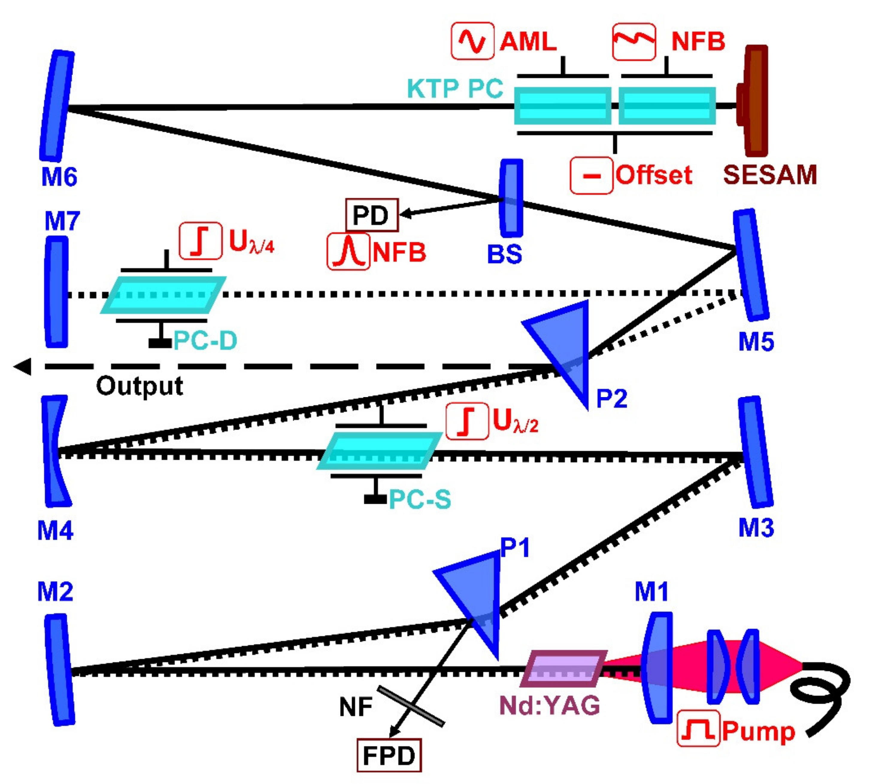
The optical scheme of a picosecond laser based on double-crystal thermo-compensated Y-cut KTP PC is shown in Figure 5. The master oscillator cavity is formed by convex mirror M1, flat mirrors M2, M3, M5, M6, concave mirror M4 and SESAM. The optical path in the oscillator is shown by the solid line. Concave mirror M4 with a curvature radius of ~150 cm is located near the center of the cavity. The curvature radius of the cavity end convex mirror M1 is 200 cm. The Nd:YAG active laser crystal, 10 mm in length and 5 mm in diameter, is coated on both faces at 1064 and 808 nm and is placed close to M1. The crystal is end-pumped by a fiber-coupled quasi-CW diode laser array (Jenoptik, Jena, Germany) with a maximum peak power of 70 W and center wavelength at 808 nm. We set the peak pump power to 80% of its maximum for the safety of the diode laser array, which is about 56 W. Pump radiation is launched onto Nd:YAG crystal through M1, which was coated for high reflection at the fundamental wavelength of 1064 nm and high transmission at the pump wavelength of 808 nm. All other mirrors were coated for high reflection at 1064 nm. The polarizing calcite 30° prisms P1 and P2 are antireflection coated for 1064 nm. P1 is used for the selection of vertical polarization within the oscillator cavity. P2 is tuned to support vertical polarization in the oscillator cavity. Vertical polarization is extraordinary in the P1 and P2. SESAM works as an end mirror on the opposite side of the cavity. Most principal SESAM parameters for proper master oscillator passive mode-locking operation are modulation depth and recovery time. They usually can be selected as 8–12% and 15–25 ps, respectively.
The KTP PC is placed near SESAM. One section of the PC is used for applying the AML sinusoidal voltage with an amplitude of ~250 V. Mode-locking frequency is defined by master oscillator cavity length and is 51.2 MHz; this corresponds to half the round trip frequency at the cavity optical length of 146.5 cm. Another section of the Pockels cell is used for the applying of properly delayed NFB signal proportional to the master oscillator pulse energy. A small part of pulses energy is reflected from the beam splitter BS and is sent through a necessary length fiber onto a fiber-coupled photodiode PD, of which the signal is amplified in an electronic circuit and is applied in a proper phase to the KTP PC section to realize the NFB. The average NFB voltage is ~100 V. The common electrode of both KTP PC sections is used to apply offset voltage in order to improve NFB efficiency [53].
After a double pass of the radiation through the KTP PC, its linear polarization turns into an elliptical one. Calcite prism P2 takes the horizontally polarized component out of the cavity. Thus, KTP PC combined with P2 works as an amplitude modulator, which introduces the required level of losses to provide the formation of a stable picosecond pulse.
Figure 6a illustrates picosecond pulse formation in the master oscillator under combined action of active and passive mode-locking and NFB control. A small fraction of the generated radiation reflected by the prism face is detected by a fast photodiode (FPD) and is observed with the oscilloscope. One can see in Figure 6a that generation starts after the 1/5 screen scan (total screen duration corresponds to 10 µs). The moment when the generation starts corresponds to the falling edge of the pump pulse when the inverse population reaches its maximum. The energy of the optical pulse circulating inside the oscillator cavity demonstrates transient behavior and decaying oscillations up to almost 2 µs that reflect the stabilizing action of the NFB signal. Then, the pulse energy reaches the steady-state value on a level approximately equal to 4 µJ. This energy corresponds to the SESAM saturation fluence that provides the most effective pulse shortening and is well below the SESAM damage threshold. As a result, pulses with stable width and energy traveling inside the oscillator cavity are produced in each laser shot. The picture observed on the oscilloscope is the so-called “long train” of picosecond pulses.
Without passive mode-locking (if using a plane mirror instead of SESAM), pulses with a duration of 300–500 ps are produced. We used SESAM with an absorbance of 13%, modulation depth of 8% and relaxation time of 25 ps. This provided pulse is shortening down to 25 ps. The ~5 µs duration of the “long train” before the cavity switching approximately corresponds to 490 cavity round trips, which is enough to achieve stable, close to the transform-limited pulse that can be further amplified in a regenerative regime. The inset in Figure 6a demonstrates an expanded fragment of the “long train” in its flat part. The pulse amplitudes look to be alternating; it is a result of electrical interference of the photodiode circuit signal with the parasitic one attributed to driving AML high voltage signal with a frequency of 51.2 MHz. The AML voltage starts to be applied only 1.5 µs before the optical generation; this is well seen in the initial part of the waveform and is switched off just after the optical generation ends. It is for better safety of the KTP PC crystals (see also, Figure 7).
It should be noted that only a part of the population inversion is spent during the 5 µs stage of stable picosecond pulse formation (about a half of the total duration of the “long train”). It is quite reasonable to utilize the residual part of the population inversion for further amplification using the regenerative scheme. The regenerative amplifier cavity of similar (not necessarily exactly equal) length as the master oscillator is formed by mirrors M1–M5 and M7. The corresponding optical path is indicated in Figure 5 by the dotted line. Then, the master oscillator and the regenerative amplifier have one common cavity shoulder (mirrors M1–M5) containing the Nd:YAG crystal. Picosecond pulse switching into the regenerative amplifier is fulfilled by applying half-wave step voltage of 6400 V to DKDP Pockels cell PC-S ~5 µs after the generation start. Due to the rotation of the pulse polarization 90° in PC-S, the laser beam passes through calcite prism P2 as “ordinary” and, therefore, is deflected at an angle of approximately 5° lower than the “extraordinary” one. In this way, the regenerative amplifier begins to function. The picosecond pulse circulates inside the regenerative amplifier cavity with minimal losses and is amplified owing to the remaining inverse population up to its depletion. This looks in the oscilloscope like a “short train” formation. Figure 6b illustrates the switching from the “long train” to the “short” one. The front of PC-S half-wave voltage is indicated by the step sign. The positions of several pulses of the “long train” are indicated by short arrows; the distances between them are equal to 10.2 ns. Meanwhile, the intervals between amplified pulses of the “short train” indicated by the long arrows are equal to 10.7 ns. Unequal values of time intervals between pulses in “long train” and “short train” reflect the difference in the oscillator and the regenerative amplifier cavities lengths.
When the pulse circulating in the regenerative amplifier reaches the maximum of energy, it is extracted from the cavity by means of P2 applying a quarter-wave dumping step voltage of 3200 V to DKDP Pockels cell PC-D placed by the fully reflecting end mirror M7. The double pass through PC-D leads to 90° polarization rotation and, therefore, to deflection in P2 of approximately 5° larger. The output radiation path is shown by the dashed line in Figure 5. Figure 6c illustrates the “short train” terminated at the moment just before the pulse with maximum energy of the train. The front of the PC-D quarter-wave voltage is indicated by the step sign in Figure 6c. The vertical dashed line corresponds to the time position of the extracted pulse. The time delay between step voltages applied to PC-S and PC-D is 120 ns; that is, the regenerative amplification stage takes 11 round trips.
Comparing amplitudes of pulses in the initial part of the “short train” (see Figure 6b,c), one can conclude that the amplification per round trip in the unsaturated regime is approximately equal to 2, and during the last four round trips before cavity dumping, the laser pulse is amplified approximately twice in the regime close to saturation (see Figure 6c). In order to estimate the energy of the pulse switched from the oscillator cavity to the cavity of the regenerative amplifier, at the very beginning of the regenerative amplification stage, we used a power meter installed in front of PC-D, which has shown a value of 0.4 mW at a repetition rate of 100 Hz. Then, the single pulse energy on the regenerative amplifier input was 4 µJ. This is the energy of the pulse traveling in the oscillator just before the moment of switching. Based on the unsaturated amplification value 2, one can conclude that approximately the same amplification occurred during the whole oscillator stage corresponding to the “long train”. That is, the total losses during each round trip in the oscillator cavity were about 50% of 4 µJ, and 2 µJ energy pulse returns to the laser crystal for the next amplification. The losses are attributed to the imperfect reflection of mirrors, imperfect antireflection coatings of laser crystal, Pockels cells, prisms, reflection on dividing plate, absorption in optical elements, residual absorption of SESAM, and the main part of radiation loss is due to the polarisation selection on P2 in the frame of NFB action. The total optical losses during 490 round trips can be estimated as 0.98 mJ. In the process of regenerative amplification, a picosecond pulse of approximately 2 µJ energy rises up to the energy of about 1.6 mJ.
It should be noted that the noticeable noise in the vicinity of the switching step signal is attributed to parasitic electrical signal induced in the photo-detector scheme by a high-voltage PC-S key circuit. Noisy decay after the terminated “short train” is attributed to the long discharge of the saturated PD capacity and electrical interference from the high-voltage PC-D key circuit.
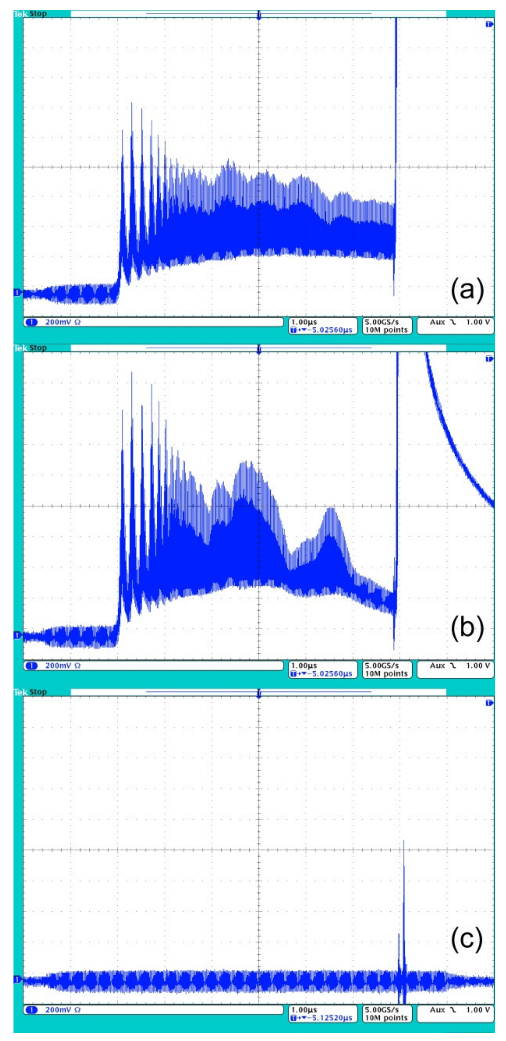
At 56 W pump peak power and 200 µs pump pulse width, the scheme allows us to obtain stable operation with a ~1.6 mJ output pulse energy in the repetition rates range from 0 to about 200 Hz, which corresponds to the oscillator cavity stability region taking into account the thermal lens in the active crystal [56]. Flat dependence of output pulse energy on repetition rate from lower to higher frequencies indicates that aberrational losses are still insignificant. Pulse-to-pulse energy instability is within 1%. The laser scheme is very stable and is able to work stably in a laboratory environment for many hours, being, however, sensitive to environmental temperature fluctuations above ~5 degrees. The parameters are similar to those for the laser with RTP Pockels cell [54,55]. Some higher single pulse energy is achieved owing to reducing losses at the oscillator stage. If not to make special efforts for thermal lens compensation, the repetition rate increase above 200 Hz is accompanied by a loss of generation stability that visually manifests itself in the appearance of “long train” envelope irregularities and in a gradual output radiation failure (see Figure 7). In Figure 7a, corresponding to a repetition rate of ~210 Hz, the envelope shape is not flat, while the amplitude is quite high at the moment of the cavity switching and the intensive “short train” grows sharply. In Figure 7b observed at 230 Hz, the main part of the envelope gradually decays before cavity switching, the envelope structure is not resolved, and the “short train” is much less intensive. Moreover, there is only a parasitic signal of electric interference attributed to the AML signal circuit, which is visible in Figure 7c at pump pulse repetition rate 280 Hz, while the optical generation does not rise. Generation failure at the repetition rates above 200 Hz is mainly attributed to the exit of the oscillator cavity from the region of stability due to an increase in the strength of the thermal lens with the average pump power growth. Therefore, the “long train” waveform can serve as an indicator of operation quality and stability. In principle, other possible reasons for the generation violation, such as a decrease in the pump power level, or a disturbed resonator adjusting will manifest themselves in a similar way in the long train degradation. In general, of course, the mechanisms of laser operation disruption are quite complicated and require thorough analysis.
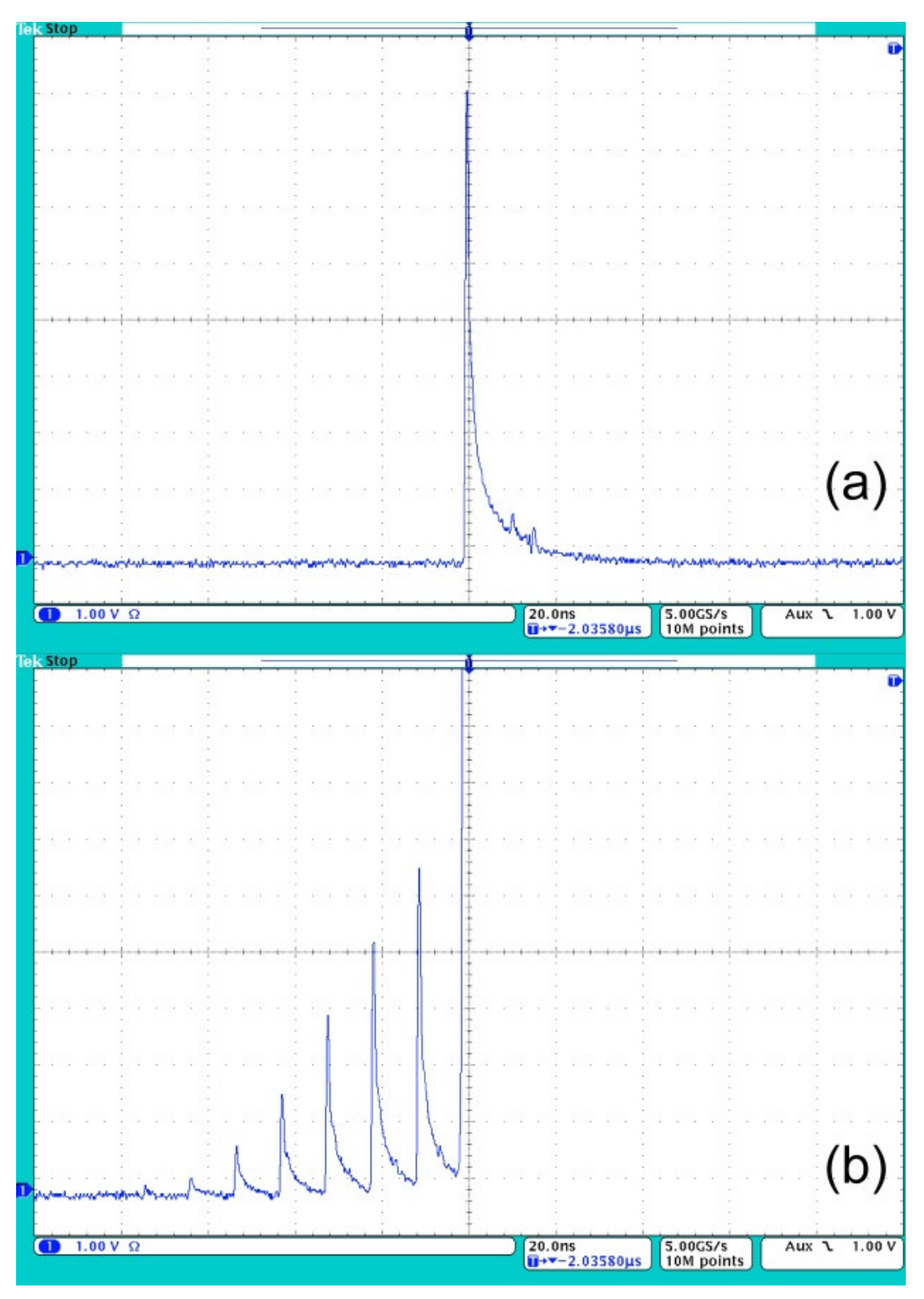
Waveforms of output picosecond pulse and of residual pre-pulses registered in the laser output and illustrated in Figure 8 allow us to evaluate the corresponding output picosecond pulse contrast value. A small fraction of radiation just at the laser output was selected by a beam splitter, attenuated with the use of a set of neutral glass filters and then detected with a fast photodiode. Attenuation was adjusted to observe without saturation, signals of the main pulse (Figure 8a) and of the pre-pulses corresponding to the radiation of the previous pulse round trips in the regenerative amplifier, transmitted to the output due to depolarization effects in PC-D (Figure 8b). Both measurements were made with the same oscilloscope sensitivity. The single main pulse presented in Figure 8a was measured using an additional neutral filter NG-10 of 3 mm thickness with an absorption of ~2 × 10³. In Figure 8b, filter NG-8 was removed, and the main pulse became saturated. One can conclude that the contrast value of the main pulse respective to pre-pulses is close to 5000.
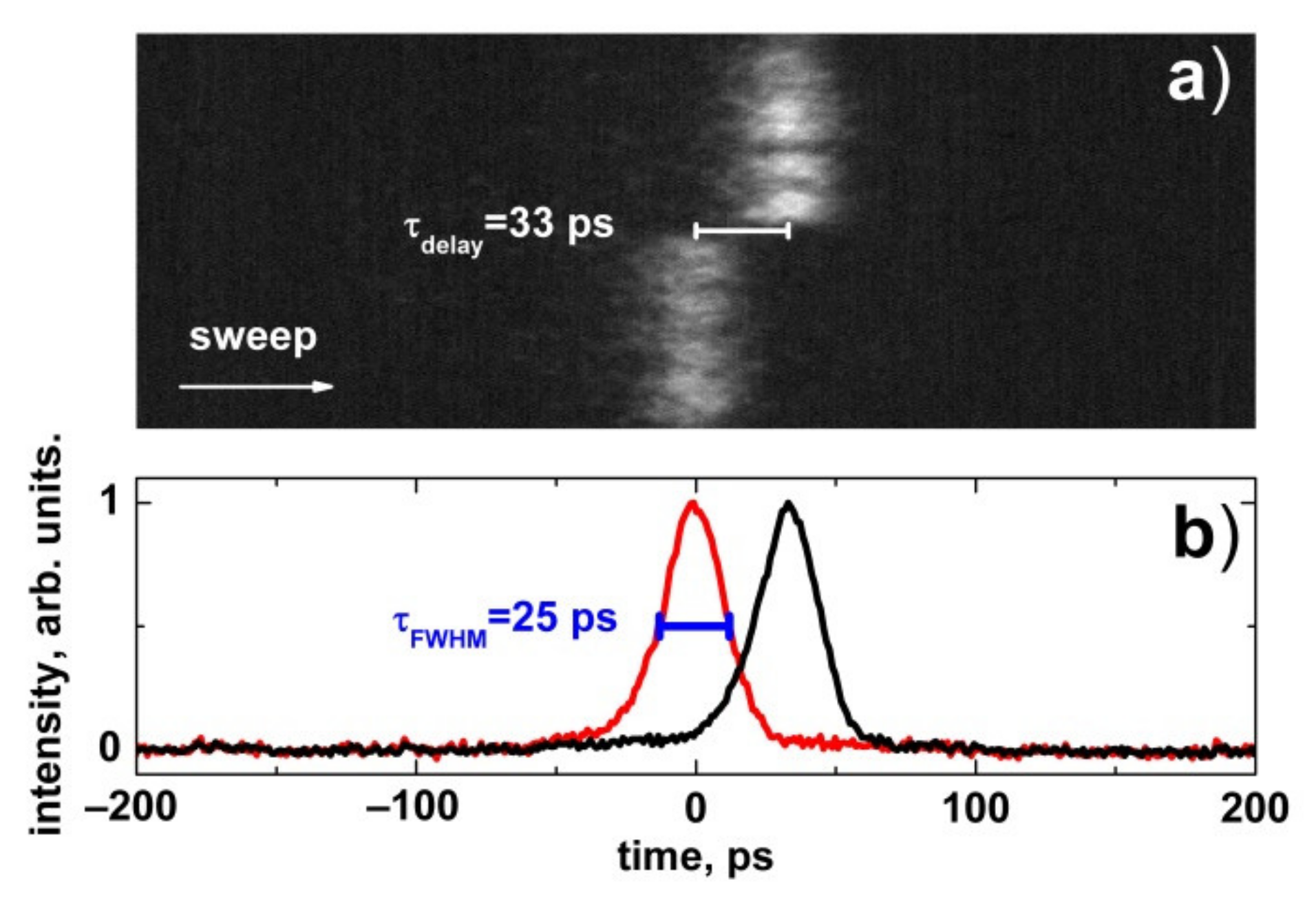
The single output pulse duration was measured with the use of a picoseconds streak camera “Agat” with a time resolution of 2 ps and a sweep factor of 100 ps/cm equipped with a photo-cathode S1. For time calibration, a fused quartz plate providing a delay time of 33 ps was introduced into the upper half of the laser beam falling on the entrance slit. Analysis of the intensity profile allowed us to determine the duration of the pulse to be 25 ps. The recorded image and its analysis result are presented in Figure 9a,b, respectively.

3. Discussion

KTP-based Pockels cells expand the line of available fast control key elements for high-peak-power pulsed-periodic picosecond lasers. In the present work, Y-cut KTP was chosen for PC assembling that was mainly motivated by the lowest unwanted SH and TH parasitic conversion. Figure 6a–c demonstrates an example of stable generation stages of such laser. This is characterized by a round trip unsaturated amplification value of ~2 that can be considered optimal for the present scheme. This corresponds to the round trip loss level of ~50%. In short, lower amplification does not provide fast enough picosecond pulses formation. While with a greater one, the present negative feedback circuit is not able to control the generation development. Moreover, a greater amplification value would demand higher pump power, resulting in additional thermal load on the Nd:YAG crystal accompanied by an increase in the proportion of aberration losses and in a reduced stability range of the oscillator cavity. The inverse population remaining after the oscillation process should be utilized for regenerative amplification. However, the proportion of useless losses increases due to aberrations. A possible negative role of incomplete consumption of inverse population for generation stability can be illustrated by means of a rather simple observation. If we block the beam circulating in the regenerative amplifier at a repetition rate close to the edge of the stability region, we see that the stable and reproducible envelope shape (as in Figure 6a) turns into an irregular and ragged one (similar to that shown in Figure 7a,b) or even the lack of generation (Figure 7c). It obviously can be explained by the fact that the remaining inverse population is not spent on regenerative amplification of the light pulse but is converted into heat. This can cause additional heat load on the active crystal and the oscillator cavity instability.
It is natural to suppose that irregular and ragged envelope shape and unstable generation can be explained not only by the thermal lens effect in the Nd:YAG crystal but also by possible mode-locking degradation caused by KTP Pockels cell thermal compensation condition violation due to the heating of KTP crystal cell sections induced by radiation absorption. Detailed analysis of this task promises to be rather complicated, at least due to the fact that the total amount of the generated and absorbed third harmonic is not known for certain. For a rough upper estimation, let us suppose that the second harmonic conversion efficiency is about 2% (similar to that for X-cut KTP PCs), and then half of it turns into the third harmonic. Each picosecond pulse of up to 4 µJ energy makes ~500 round trips during the oscillation process. This means, taking into account laser repetition rate, that the third harmonic absorbed power is about 1 × 10⁻³ W. This may be a source of appreciable PC heating. To make a more reasonable statement on this subject, we decided to verify whether third-harmonic radiation can lead to fundamental wavelength beam depolarization at the Y-cut KTP PC using the scheme presented in Figure 10.
We utilized a supplementary Nd:YAG picosecond laser as a source of 30 ps pulses of vertically polarized radiation at the repetition rate of 20 Hz and a two-pass arc amplifier to obtain single pulse energy of ~10 mJ at a wavelength of 1064 nm. As a result of partial sequential conversion to the second and third harmonics, pulse energy at 355 nm was equal to ~1 mJ and, correspondingly, the average third harmonic absorbed power was 2 × 10⁻² W, which is more than one order of magnitude higher than the estimation result given above. Moreover, almost all this third harmonic radiation in this single pass scheme was absorbed within the first KTP section. That is, in this test experiment, the Y-cut KTP PC sections can be, in principle, less uniformly heated than in the case of laser operation, where radiation pulse travels in both directions. The polarization contrast of the Y-cut KTP PC combined with calcite prism was not worse at ~2 × 10⁻², and we did not observe any noticeable contrast decrease. Thus, we can conclude that in the discussed laser scheme and at the present level of average power, the absorption of the third harmonic does not seem to be a reason for Y-cut KTP PC thermal compensation condition violation. At the same time, at higher repetition rates and higher absorbed average power, a problem may arise that deserves further investigation.
In view of the development of the advanced laser schemes with higher repetition rates and average power, one can note that KTP crystals grown using contemporary technologies [1,49,76,77] are characterized by high electrical resistivity, have a high optical birefringence uniformity and low absorption at a wavelength of 1064 nm. The linear absorption of KTP crystals at a wavelength of 1064 nm reaches a value of 10−5 cm−1 (10 ppm). Crystal growth and PC assembling technologies are being improved, and nowadays, the best samples of KTP and RTP crystal PCs have similar parameters of linear absorption, extinction ratio (up to 30 dB, 1:1000) and damage threshold (up to 1.0 GW/cm2, reduced to 10 ns pulse regime) [71,78,79,80,81,82]. As for picosecond pulses, PC performance can be maintained up to 25 GW/cm2 [83].
Furthermore, with regard to higher repetition rate laser schemes, there are significant restrictions on the use of switching and dumping Pockels cells based on DKDP crystals when the laser operates in the kilohertz frequency range [84]. These crystals have a significant piezoelectric effect, as a result of which their transmission is strongly influenced by the secondary electro-optical, or photo-elastic, effect [85]. Due to the inertia of the secondary electro-optical effect, it is possible to realize a single pulsed or pulsed-periodic laser generation only if the pulse repetition period exceeds the decay time of acoustic processes in the crystal, which lies in the sub-millisecond range. However, with a shorter period, in particular, in the kilohertz frequency range, the secondary electro-optical effect can have an unpredictable effect on the light transmission of the modulator and, consequently, on the generation intensity. There are methods for suppressing acoustic vibrations in electro-optical modulators based on the use of special damping frames [86,87,88]. Such approaches allow the acoustic processes in crystals to be significantly reduced and modulators based on such crystals for long-time operation to be used. It should be noted, however, that at the moment, there are no suppliers producing such modulators. The piezoelectric effect in KTP and RTP crystals is much smaller, and modulators based on them can be used without restrictions due to the acoustic problems at kHz pulse repetition rates [89]. While the problems connected with UV absorption can arise.
As discussed above, it should be assumed that by using these advanced crystals, some questions may arise connected to nonlinear conversion, absorption of the converted radiation and stimulated processes at high-peak-power radiation. Previous experience with RTP PCs confirms this. The results of SH and TH measurements show that the essential part (up to several percent and higher) of high-peak-power radiation on the fundamental wavelength can be converted into SH and TH; the last is effectively absorbed. Obviously, this can result in a number of undesirable effects, such as: (i) losses of fundamental wavelength radiation, significantly exceeding the pure liner absorption; (ii) additional PC’s crystal heating that could potentially contribute to the contrast decrease; (iii) crystals degrading and damage, gray track formation, the mechanism of which requires detailed study. Aside from the TH generation, similar consequences may be inspired by other nonlinear conversion processes, such as fourth harmonics generation or stimulated Raman scattering.
The data presented in Table 2 allows us to judge the SH and TH conversion levels at peak power parameters typical for high-peak-power picosecond lasers. The differences between RTP and KTP in nonlinear conversion features shown in Section 2.3 require further careful analysis. Figure 4 illustrates that in the KTP cells, SH and TH are generated near collinearly, while in the RTP ones, SH and TH have multi-beam, essentially non-collinear characters. That is, the nature of phase matching at both the SH and TH processes in the KTP and RTP PC crystals is significantly different. What should be recalled in this regard is that TH in KTP may be generated on cubic nonlinearity even larger than on the quadratic one; it was shown [64] for laser emitting at 1618 nm. For fundamental radiation of 1064 nm, TH conversion efficiency can essentially change near the absorption line. For thorough investigation, it ought to obtain data on nonlinear coefficients and principal refractive indexes for TH wavelength. The use of Y-cut KTP PC in the considered laser scheme is still justified due to the minimal SH and TH levels.

4. Conclusions

Double-crystal, thermally compensated Pockels cell based on KTP crystals of Y-cut direction is used as a key element for the implementation of a picosecond pulse-periodic high-peak-power Nd:YAG laser scheme with electro-optical operation control. The cell is assembled using a pair of equal-length crystals grown according to high-resistivity technology. The laser scheme uses an active-passive mode-locked and negative feedback-controlled master oscillator and regenerative amplifier based on a common end-diode-qcw-pumped Nd:YAG crystal. The scheme provides stable operation with an output pulse energy of 1.6 mJ and a duration of 25 ps within a repetition rate range from a single shot to 200 Hz. Operational details are presented. The employing of electro-optical KTP-family crystal-based Pockels cells in picosecond lasers of higher peak and average power was discussed. The associated problem of parasitic second and third harmonic generations of the fundamental high-peak-power picosecond radiation wavelength in the PC crystals was considered, and special comparative measurements with the Pockels cells based on KTP and RTP crystals of both X-cut and Y-cut directions were made with the use of an auxiliary high-peak-power picosecond Nd:YAG laser. It was demonstrated that second and third harmonics efficiencies were the lowest in the Pockels cell based on KTP crystals of the Y-cut direction. Moreover, the experiments were fulfilled to find out whether the intense TH radiation absorbed in the Y-cut KTP PC crystals may affect its contrast. It was shown that at the average TH power of 2 × 10⁻² W, no visible reduction in contrast was observed. At the same time, the estimates show that at higher values of peak and average power, similar effects can occur and ought to be taken into account.

Author Contributions

Investigation, V.M., A.O., V.T., D.Y., V.R., A.G. and S.D. All authors contributed to the manuscript. All authors have read and agreed to the published version of the manuscript.

Funding

The work is partially supported by the Moscow State University Program of Development.

Data Availability Statement

The data presented in the study are available in this article. Details are available on request from the corresponding author.

Conflicts of Interest

The authors declare no conflict of interest.

References

  1. Montello, A.; Nishihara, M.; Rich, J.W.; Adamovich, I.V.; Lempert, W.R. Picosecond CARS measurements of nitrogen rotational/translational and vibrational temperature in a nonequilibrium Mach 5 flow. Exp. Fluids 2013, 54, 1422. [Google Scholar] [CrossRef]
  2. Seeger, T.; Kiefer, J.; Leipertz, A.; Patterson, B.D.; Kliewer, C.J.; Settersten, T.B. Picosecond time-resolved pure-rotational coherent anti-Stokes Raman spectroscopy for N2 thermometry. Opt. Lett. 2009, 34, 3755–3757. [Google Scholar] [CrossRef] [PubMed] [Green Version]
  3. Arakcheev, V.G.; Kireev, V.V.; Morozov, V.B.; Olenin, A.N.; Tunkin, V.G.; Valeev, A.A.; Yakovlev, D.V. Collisionally induced dephasing and rotational energy transfer in CO2 Fermi dyad “blue” Q-branch 1388 cm−1. J. Raman Spectrosc. 2007, 38, 1046–1051. [Google Scholar] [CrossRef]
  4. Intartaglia, R.; Bagga, K.; Brandi, F. Study on the productivity of silicon nanoparticles by picosecond laser ablation in water: Towards gram per hour yield. Opt. Express 2014, 22, 3117–3127. [Google Scholar] [CrossRef]
  5. Scotti, G.; Trusheim, D.; Kanninen, P.; Naumenko, D.; Shulz-Ruhtenberg, M.; Snitka, V.; Kallio, T.; Franssila, S. Picosecond laser ablation for silicon micro fuel cell fabrication. J. Micromech. Microeng. 2013, 23, 055021. [Google Scholar] [CrossRef] [Green Version]
  6. Vereshchagin, A.K.; Vereshchagin, K.A.; Morozov, V.B.; Tunkin, V.G. Non-collinear optical parametric amplifier for time-resolved broadband picosecond CARS. J. Raman Spectrosc. 2014, 45, 507–514. [Google Scholar] [CrossRef]
  7. Gacheva, E.I.; Poteomkin, A.K.; Mironov, S.Y.; Zelenogorskii, V.V.; Khazanov, E.A.; Yushkov, K.B.; Chizhikov, A.I.; Molchanov, V.Y. Fiber laser with random-access pulse train profiling for a photoinjector driver. Phot. Res. 2017, 5, 293–298. [Google Scholar] [CrossRef]
  8. Petrarca, M.; Martyanov, M.; Divall, M.S.; Luchinin, G. Study of the powerful Nd:YLF laser amplifiers for the CTF3 photoinjectors. IEEE J. Quantum Electron. 2011, 47, 306–313. [Google Scholar] [CrossRef] [Green Version]
  9. Seeber, G. Laser Ranging. In Satellite Geodesy, 2nd ed.; Walter de Gruyter: Berlin, Germany, 2003; Chapter 8; pp. 405–442. [Google Scholar]
  10. Gourine, B. French transportable laser ranging station: Positioning campaigns for satellite altimeter calibration missions in occidental Mediterranean Sea. Larhyss J. 2013, 12, 57–69. [Google Scholar] [CrossRef]
  11. Dickey, J.O.; Bender, P.L.; Faller, J.E.; Newhall, X.X.; Ricklefs, R.L.; Ries, J.G.; Shelus, P.J.; Veillet, C.; Whipple, A.L.; Wiant, J.R.; et al. Lunar laser ranging: A continuing legacy of the Apollo Program. Science 1994, 265, 482–490. [Google Scholar] [CrossRef] [Green Version]
  12. Williams, J.G.; Turyshev, S.G.; Boggs, D.H. Progress in Lunar laser ranging tests of relativistic gravity. Phys. Rev. Lett. 2004, 93, 261101. [Google Scholar] [CrossRef] [Green Version]
  13. Mourou, G.; Stancampiano, C.V.; Antonetti, A.; Orszag, A. Picosecond microwave pulses generated with a subpicosecond laser-driven semiconductor switch. Appl. Phys. Lett. 1981, 39, 295–296. [Google Scholar] [CrossRef]
  14. Vergne, B.; Couderc, V.; Barthelemy, A.; Lalande, M.; Bertrand, V.; Gontier, D. High-power bipolar picosecond pulse generation using optically activated travelling wave generator. Microw. Opt. Technol. Lett. 2006, 48, 1645–1648. [Google Scholar] [CrossRef]
  15. Chung, C.; Lin, Y.; Wu, K.; Tai, W.; Chu, S.; Lee, Y.; Hwu, Y.; Lee, Y. Coherent anti-Stokes Raman scattering microscopy using a single-pass picoseconds supercontinuum-seeded optical parametric amplifier. Opt. Express 2010, 18, 6116–6122. [Google Scholar] [CrossRef]
  16. Kawakami, R.; Sawada, K.; Sato, A.; Hibi, T.; Kozawa, Y.; Sato, S.; Yokoyama, H.; Nemoto, T. Visualizing hippocampal neurons with in vivo two-photon microscopy using a 1030 nm picosecond pulse laser. Sci. Rep. 2013, 3, 1014. [Google Scholar] [CrossRef] [Green Version]
  17. Dierickx, C. Using normal and high pulse coverage with picosecond laser treatment of wrinkles and acne scarring: Long term clinical observations. Lasers Surg. Med. 2017, 50, 51–55. [Google Scholar] [CrossRef] [Green Version]
  18. Reiter, O.; Atzmony, L.; Akerman, L.; Levi, A.; Kershenovich, R.; Lapidoth, M.; Mimouni, D. Picosecond lasers for tattoo removal: A systematic review. Lasers Med. Sci. 2016, 31, 1397–1405. [Google Scholar] [CrossRef]
  19. Geerling, G.; Roider, J.; Schmidt-Erfurt, U.; Nahen, K.; El-Hifnawi, E.-S.; Laqua, H.; Vogel, A. Initial clinical experience with the picosecond Nd:YLF laser for intraocular therapeutic applications. Br. J. Ophthalmol. 1998, 82, 504–509. [Google Scholar] [CrossRef]
  20. Lindstrom, R.L. (Ed.) Textbook of Refractive Laser Assisted Cataract Surgery (ReLACS); Springer: New York, NY, USA, 2013; pp. 1–278. [Google Scholar] [CrossRef]
  21. Petersen, H.; Tavakoli, F.; Kruber, S.; Muenscher, A.; Gliese, A.; Hansen, N.; Uschold, S.; Eggert, D.; Robertson, W.; Gosau, T.; et al. Comparative study of wound healing in rat skin following incision with a novel picosecond infrared laser (PIRL) and different surgical modalities. Lasers Surg. Med. 2016, 48, 385–391. [Google Scholar] [CrossRef] [Green Version]
  22. Koechner, W. Solid-State Laser Engineering, 6th ed.; Springer: New York, NY, USA, 2006; pp. 534–586. [Google Scholar] [CrossRef]
  23. Agnesi, A.; Pirzio, F. High gain solid-state amplifiers for picosecond pulses. In Advances in Solid-State Lasers: Development and Applications; Grishin, M., Ed.; Intech: Rijeka, Croatia, 2010; pp. 213–238. [Google Scholar] [CrossRef] [Green Version]
  24. Osterink, L.M.; Foster, J.D. A mode-locked Nd:YAG laser. J. Appl. Phys. 1968, 39, 4163–4165. [Google Scholar] [CrossRef]
  25. Zaporozhchenko, V.A.; Tylets, N.A. Time locking of optical pulses to an external signal in pulsed lasers with active mode locking. Quantum Electron. 1996, 26, 512–516. [Google Scholar] [CrossRef]
  26. Minamikawa, T.; Tanimoto, N.; Hashimoto, M.; Araki, T.; Kobayashi, M.; Fujita, K.; Kawata, S. Jitter reduction of two synchronized picosecond mode-locked lasers using balanced cross-correlator with two-photon detectors. Appl. Phys. Lett. 2006, 89, 191101. [Google Scholar] [CrossRef]
  27. Brito Cruz, C.H.; De Martini, F.; Fragnito, H.L.; Palange, E. Picosecond pulse generation by intracavity nonlinear compression in self-injected Nd:YAG laser. Opt. Commun. 1982, 40, 298–301. [Google Scholar] [CrossRef]
  28. Komarov, K.P.; Kuch’yanov, A.S.; Ugozhaev, V.D. Steady-state ultrashort pulses generated by passive mode locking of a solid-state laser with an active feedback. Sov. J. Quantum Electron. 1986, 16, 520–524. [Google Scholar] [CrossRef]
  29. Del Corno, A.; Gabetta, G.; Reali, G.C.; Kubecek, V.; Marek, J. Active-passive mode-locked Nd:YAG laser with passive negative feedback. Opt. Lett. 1990, 15, 734–736. [Google Scholar] [CrossRef] [PubMed]
  30. Burneika, K.; Grigonis, R.; Piskarskas, A.; Sinkyavichius, G.; Sirutkaitis, V. A subpicosecond high-stable neodymium-phosphate-glass laser with passive mode locking and negative feedback. Sov. J. Quantum Electron. 1988, 18, 1034–1035. [Google Scholar] [CrossRef]
  31. Val’shin, A.M.; Gordienko, V.M.; Krayushkin, S.V.; Platonenko, V.T.; Popov, V.K. Yttrium aluminate sources of ultrashort radiation pulses with a controlled resonator Q factor. Sov. J. Quantum Electron. 1986, 16, 1125–1127. [Google Scholar] [CrossRef]
  32. Heinz, P.; Kriegleder, W.; Laubereau, A. Feedback control of an actively-passively mode-locked Nd:Glass laser. Appl. Phys. A 1987, 43, 209–212. [Google Scholar] [CrossRef]
  33. Heinz, P.; Laubereau, A. Stable generation of subpicosecond pulses by feedback-controlled mode locking of a Nd:Glass laser. J. Opt. Soc. Am. B 1989, 6, 1574–1578. [Google Scholar] [CrossRef]
  34. Murray, J.E.; Lowdermilk, W.H. Nd:YAG regenerative amplifier. J. Appl. Phys. B 1980, 51, 3548–3555. [Google Scholar] [CrossRef]
  35. Zayhowski, J.J. Passively Q-switched microchip lasers. In Solid-State Lasers and Applications; Sennaroglu, A., Ed.; Taylor & Francis Group: Boca Raton, FL, USA, 2007; pp. 1–76. [Google Scholar]
  36. Keller, U.; Weingarten, K.J.; Kärtner, F.X.; Kopf, D.; Braun, B.; Jung, I.D.; Fluck, R.; Honninger, C.; Matuschek, N.; Der Au, J.A. Semiconductor saturable absorber mirrors (SESAM’s) for femtosecond to nanosecond pulse generation in solid-state lasers. IEEE. Sel. Top. Quantum Electron. 1996, 2, 1077–1079. [Google Scholar] [CrossRef] [Green Version]
  37. Keller, U. Recent development in compact ultrafast lasers. Nature 2003, 424, 831–838. [Google Scholar] [CrossRef]
  38. Keller, U. Ultrafast solid-state laser oscillators: A success story for the last 20 years with no end in sight. Appl. Phys. B 2010, 100, 15–28. [Google Scholar] [CrossRef] [Green Version]
  39. Karnaukhov, A.A.; Morozov, V.B.; Olenin, A.N.; Yakovlev, D.V. Precise synchronization of qcw pumped active-passive mode locked picosecond lasers. In Journal of Physics: Conference; IOP Publishing: Bristol, UK, 2013; Volume 414, p. 012027. [Google Scholar] [CrossRef] [Green Version]
  40. Palese, S.; Schilling, L.; Wang, X.D.; Dwayne Miller, R.J.; Guo, Z.; Brown, D. Frequency modulated mode locking of a diode laser pumped Nd: LiYF4 laser utilizing a KTiOPO4 phase modulator. Appl. Phys. Lett. 2007, 61, 2257–2259. [Google Scholar] [CrossRef]
  41. Mazur, M.M.; Mazur, L.I.; Sirotkin, A.A.; Ryabinin, A.V.; Shorin, V.N. Acousto-optic modulators of high-power laser radiation on the basis of KGW and KYW crystals. Quantum Electron. 2020, 50, 957–961. [Google Scholar] [CrossRef]
  42. Liu, J.; Xu, G.; Liu, F.; Kityk, I.; Liu, X.; Zhen, Z. Recent advances in polymer electro-optic modulators. RSC Adv. 2015, 5, 15784–15794. [Google Scholar] [CrossRef]
  43. Chen, A.; Murphy, E. Broadband Optical Modulators: Science, Technology, and Applications; CRC Press: Boca Raton, FL, USA; London, UK; New York, NY, USA, 2012; p. 568. [Google Scholar]
  44. Rukin, S.N. Pulsed power technology based on semiconductor opening switches: A review. Rev. Sci. Instrum. 2020, 91, 011501. [Google Scholar] [CrossRef]
  45. Kesar, A.S. A compact, 10-kV, 2-ns risetime pulsed-power circuit based on off-the-shelf components. IEEE Trans. Plasma Sci. 2018, 46, 594–597. [Google Scholar] [CrossRef]
  46. Dwayne Miller, R.J.; Bonner, C.; Palese, S.; Pereyra, A.; Schling, L.; Walmsley, A.; Wang, D.; Guo, Z. Development and applications of electro-optics for high power systems. In Diode Pumping of Average-Power Solid State Lasers; International Society for Optics and Photonics: Bellingham, WA, USA, 1993; Volume 1865, pp. 100–110. [Google Scholar] [CrossRef]
  47. Bierlein, J.D.; Vanherzeele, H. Potassium titanyl phosphate: Properties and new applications. J. Opt. Soc. Am. B 1989, 6, 622–633. [Google Scholar] [CrossRef]
  48. Ebbers, C.A.; Velsko, S.P. High average power KTiOPO4 electrooptic Q-switch. Appl. Phys. Lett. 1995, 67, 4593–4595. [Google Scholar] [CrossRef]
  49. Roth, M.; Tseitlin, M.; Angert, N. Oxide crystals for electro-optic Q-switching of lasers. Glass Phys. Chem. 2005, 31, 86–95. [Google Scholar] [CrossRef]
  50. Rusov, V.A.; Serebryakov, V.A.; Kaplun, A.B.; Gorshakov, A.V. Using modulators based on KTP crystals in Nd:YAG lasers with high mean power. J. Opt. Technol. 2009, 76, 325–331. [Google Scholar] [CrossRef]
  51. Rusov, V.A.; Zakharova, N.A.; Kaplun, A.B.; Meshalkin, A.B.; Gorshakov, A.V. Study of the electrical-conductivity kinetics of KTP crystals used in the modulators of solid-state lasers. J. Opt. Technol. 2013, 80, 532–536. [Google Scholar] [CrossRef]
  52. Rusov, V.A.; Doroganov, S.V.; Kalintseva, N.A.; Narivonchik, A.S.; Skvortsov, D.V.; Serebryakov, V.A. Electro-optical modulators based on KTP crystals for high-power lasers in the mid-IR region. J. Opt. Technol. 2016, 83, 716–721. [Google Scholar] [CrossRef]
  53. Johnson, C.K.M.; Eden, D.D. Solid state modulation and demodulation of light with information from five television channels simultaneously. Proc. IEEE 1965, 53, 402–403. [Google Scholar] [CrossRef]
  54. Gorbunkov, M.V.; Konyashkin, A.V.; Kostryukov, P.V.; Morozov, V.B.; Olenin, A.N.; Rusov, V.A.; Telegin, L.S.; Tunkin, V.G.; Shabalin, Y.V.; Yakovlev, D.V. Pulsed-diode-pumped, all-solid-state, electro-optically controlled picosecond Nd:YAG lasers. Quantum Electron. 2005, 35, 2–6. [Google Scholar] [CrossRef]
  55. Mikheev, N.G.; Morozov, V.B.; Olenin, A.N.; Yakovlev, D.V. Picosecond lasers with the dynamical operation control. In Saratov Fall Meeting 2015: Third International Symposium on Optics and Biophotonics and Seventh Finnish-Russian Photonics and Laser Symposium (PALS); International Society for Optics and Photonics: Bellingham, WA, USA, 2016; Volume 9917, p. 99170A. [Google Scholar] [CrossRef]
  56. Mikheev, N.G.; Morozov, V.B.; Olenin, A.N.; Tunkin, V.G.; Yakovlev, D.V. Picosecond pulsed high-peak-power lasers. In Progress in Photon Science; Springer Series in Chemical Physics 119; Yamanouchi, K., Tunik, S., Makarov, V., Eds.; Springer Nature Switzerland AG: Cham, Switzerland, 2019; pp. 63–87. [Google Scholar] [CrossRef]
  57. Morozov, V.B.; Olenin, A.N.; Tunkin, V.G.; Yakovlev, D.V. Operation conditions for a picosecond laser with an aberration thermal lens under longitudinal pulsed diode pumping. Quantum Electron. 2011, 41, 508–514. [Google Scholar] [CrossRef]
  58. Halliburton, L.E.; Scripsick, M.P. Mechanisms and point defects responsible for the formation of gray tracks in KTP. In Solid State Lasers and Nonlinear Crystals; International Society for Optics and Photonics: Bellingham, WA, USA, 1995; Volume 2379, pp. 235–244. [Google Scholar] [CrossRef]
  59. Zhanga, Q.; Fenga, G.; Hana, J.; Li, B.; Zhub, Q.; Xieb, X. High repetition rate laser pulse induced damage in KTP crystal: Gray-tracking and catastrophic damage. Optik 2011, 122, 1313–1318. [Google Scholar] [CrossRef]
  60. Scripsic, M.P.; Edwards, G.J.; Halliburton, L.E.; Belt, R.F.; Loiacono, G.M. Effect of crystal growth on Ti3+ centers in KTiOPO4. J. Appl. Phys. 1994, 76, 773–776. [Google Scholar] [CrossRef]
  61. Martin, M.J.; Bravo, D.; Sole, R.; Diaz, F.; Lopez, F.J.; Zaldo, C. Thermal reduction of KTiOPO4 single crystals. J. Appl. Phys. 1994, 76, 7510–7518. [Google Scholar] [CrossRef]
  62. Boulanger, B.; Rousseau, I.; Fève, J.P.; Maglione, M.; Menaert, B.; Marnier, G. Optical studies of laser-induced gray-tracking in KTP. IEEE J. Quantum Electron. 1999, 35, 281–286. [Google Scholar] [CrossRef] [Green Version]
  63. Dmitriev, V.G.; Gurzadyan, G.G.; Nikogosyan, D.N. Handbook of Nonlinear Optical Crystals, 2nd ed.; Springer: Berlin/Heidelberg, Germany; New York, NY, USA, 1997; p. 413. [Google Scholar]
  64. Nikogosyan, D.N. Nonlinear Optical Crystals: A Complete Surway; Springer Since + Business Media Inc.: New York, NY, USA, 2005; p. 427. [Google Scholar]
  65. Fève, J.P.; Boulanger, B.; Guillien, Y. Efficient energy conversion for cubic third-harmonic generation that is phase matched in KTiOPO4. Opt. Lett. 2000, 25, 1373–1375. [Google Scholar] [CrossRef]
  66. Hansson, G.; Karlsson, H.; Wang, S.; Laurell, F. Transmission measurements in KTP and isomorphic compounds. Appl. Opt. 2000, 39, 5058–5069. [Google Scholar] [CrossRef]
  67. Pasiskavicius, V.; Canalias, C.; Laurell, F. High efficient stimulated Raman scattering of picosecond pulses in KTiOPO4. Appl. Phys. Lett. 2006, 88, 041110. [Google Scholar] [CrossRef]
  68. Vereshchagin, K.A.; Morozov, V.B.; Tunkin, V.G. Broadband noncollinear optical parametric amplification under low-frequency picosecond pump in homogeneous KTP crystal. J. Raman Spectrosc. 2018, 49, 1116–1127. [Google Scholar] [CrossRef]
  69. Red Optronics. KTP Crystal (KTiOPO4). Available online: http://www.redoptronics.com/KTP-crystal.html (accessed on 5 August 2021).
  70. EKSMA. KTP—Potassium Titanyl Phosphate. Available online: https://eksmaoptics.com/out/media/EKSMA_Optics_KTP_Crystals.pdf (accessed on 5 August 2021).
  71. CASIX. KTP Crystals. Available online: https://www.casix.com/products/crystal-products/non-linear-optical-crystals/ktp-crystal.shtml (accessed on 5 August 2021).
  72. Oseledchik, Y.S.; Pisarevsky, A.I.; Prosvirnin, A.L.; Starshenko, V.V.; Svitanko, N.V. Nonlinear optical properties of the flux grown RbTiOPO4 crystal. Opt. Mater. 1994, 3, 237–242. [Google Scholar] [CrossRef]
  73. Raicol Crystals. Nonlinear, Electrooptic Crystals and Elements. Available online: https://raicol.com/wp-content/uploads/catalog.pdf (accessed on 5 August 2021).
  74. Antsygin, V.D.; Mamrashev, A.A.; Nikolaev, N.A.; Potaturkin, O.I.; Kaplun, A.B. Terahertz optical properties of potassium titanyl phosphate crystals. Opt. Exp. 2014, 22, 25436–25443. [Google Scholar] [CrossRef]
  75. Raicol Crystals. RTP EO Devices. Available online: https://raicol.com/wp-content/uploads/rtp-eo-devices-updated-format.pdf (accessed on 5 August 2021).
  76. Gentec-EO. Beamage User Manual. USB 3.0 Beam Profiling Cameras. Available online: https://downloads.gentec-eo.com/prod/4a790cf9/103680-Manual-Beamage-Rev-20.pdf (accessed on 5 August 2021).
  77. Roth, M.; Angert, N.; Tseitlin, M.; Alexandrovski, A. On the optical quality of KTP crystals for nonlinear optical and electro-optic application. Opt. Mater. 2001, 16, 131–136. [Google Scholar] [CrossRef]
  78. Vazhinsky, O.T.; Vazhinskaya, K.S.; Pargachev, I.A.; Serebrennikov, L.Y.; Krakovsky, V.A. Thermo- and mechanically stable electro-optic Q-switches based on the RKTP crystal. Phys. Procedia 2017, 86, 170–175. [Google Scholar] [CrossRef]
  79. Wang, X.D.; Basseras, P.; Miller, R.J.D.; Vanherzeele, H. Investigation of KTiOPO4 electro-optic amplitude modulator. Appl. Phys. Lett. 1991, 59, 519–521. [Google Scholar] [CrossRef]
  80. Crystal Laser. RTP Electro-Optic Assemblies. Rubidium Titanyle Phosphate-RTiOPO4. Available online: https://www.cristal-laser.com/upload/produit_fiche/lg_1_1607619420_Fiche_RTP_assies_V3.pdf (accessed on 5 August 2021).
  81. Lasermetrics. Series 1147-RTP Electro-Optic Modulators and Q-Switches. Available online: http://lasermetrics.com/pdf/1147.pdf (accessed on 5 August 2021).
  82. Hildenbrand, A.; Wagner, F.R.; Natoli, J.-Y.; Commandré, V.; Albrecht, H.; Théodore, F. Laser damage investigation in nonlinear crystals: Study of KTiOPO4 (KTP) and RbTiOPO4 (RTP) crystals. Proc. SPIE 2008, 6998, 699815. [Google Scholar] [CrossRef]
  83. Pargachev, I.A.; Serebrennikov, L.Y.; Mandel, A.E.; Krakowsky, V.A.; Shandarov, S.M.; Shvartzman, G.I. Electro-optic modulators of laser radiation on the basis of high-resistance KTP crystals. Dokladi TUSURa. 2011, 24, 116–118. (In Russian) [Google Scholar]
  84. Koval, V.V.; Kornev, A.F.; Rusov, V.A. Comparison of Pockels cell based on X-cut and Y-cut KTP crystals under intense picosecond radiation. In Proceedings of the 2020 International Conference Laser Optics (ICLO), St. Petersburg, Russia, 2–6 November 2020. [Google Scholar] [CrossRef]
  85. Stephany, I.E. Piezo-optic resonances in crystals of the dihydrogen phosphate type. J. Opt. Soc. Am. 1965, 55, 136–142. [Google Scholar] [CrossRef]
  86. Belouet, C. DKDP crystals for use in the TITUS tube. Philips Technol. Rev. 1980, 39, 50–61. [Google Scholar]
  87. Kuzovkova, T.A.; Medvedev, S.K.; Nilov, E.V.; Frolov, S.V. Suppression of acoustic vibrations in electrooptic Q switches. Sov. J. Quantum Electron. 1991, 18, 1124–1127. [Google Scholar] [CrossRef]
  88. Kuzovkova, T.A.; Medvedev, S.K.; Nilov, E.V.; Frolov, S.V. Electrooptical modulator of laser quality with stable contrast. Instr. Exp. Technol. 1992, 1, 161–164. [Google Scholar]
  89. Georgiev, K.; Rusov, V.; Gagarsky, S.; Trifonov, A.; Buchvarov, I. High Energy, kHz-Repetition Rate, Q-Switched Nd:YAG Laser, Using an Electro-Optical Modulator and Variable Reflectivity Mirror, in Laser Congress 2019 (ASSL, LAC, LS&C), OSA Technical Digest 2019, p. JTh3A, 28. Available online: https://www.osapublishing.org/abstract.cfm?URI=LSC-2019-JTh3A.28 (accessed on 5 August 2021).
Figure 1. Double-crystal thermal compensation schemes for KTP and RTP PCs: (a) X-cut, (b) Y-cut. Arrows near the electrical field E indicate the input light polarization. Vertical (a) and horizontal (b) directions of E are shown as examples.
Crystals 12 00368 g001
Figure 2. Orientation of KTP crystal crystallographic axes in: (a) X-cut KTP crystal; (b) Y-cut KTP crystal. Dashed line S shows the direction of second harmonic synchronism. Bold blue arrows indicate the electric vector E direction. Open green arrows show the initial waves propagation directions.
Crystals 12 00368 g002
Figure 3. Pockels cell based on Y-cut KTP crystals photo.
Crystals 12 00368 g003
Figure 4. Fundamental radiation and harmonics intensity distributions on a matrix sensor located 20 cm behind PCs: (a) Fundamental radiation in X-cut KTP PC; (b) TH in X-cut KTP PC; (c) TH in Y-cut KTP PC; (d) fundamental radiation in RTP PC; (e) SH in Y-cut RTP; (f) TH in Y-cut RTP. Dotted quadrate counter lines indicate the projection of the PC aperture on the matrix sensor plate for the harmonics beam’s observation.
Crystals 12 00368 g004
Figure 5. Optical scheme of pulsed-periodic picosecond Nd:YAG laser. The optical path inside the master oscillator is shown by the solid line, the inside regenerative amplifier by the dotted line. The optical path of the beam leaving the picosecond laser is shown by the dashed line. KTP PC is KTP based Pockels cell, PC-S is DKDP Pockels cell of switcher and PC-D is DKDP Pockels cell of dumper. M1 is the convex mirror, M2, M3, M5, M6, M7 are flat mirrors, M4 is the concave mirror, SESAM is the semiconductor saturable absorber mirror, P1 and P2 are calcite prisms used as polarizers, BS is the beam splitter, PD is a photodiode of NFB chain and FPD is a fast photodiode.
Crystals 12 00368 g005
Figure 6. Signal of fast PD detector registered with the oscilloscope: (a) Long train of picosecond pulses; (b) Initial part of the short train; (c) Short train of picosecond pulses. PC-S Uλ/2 indicates the front of the half-wave voltage applied to the modulator PC-S; PC-D Uλ/4 indicates the front of the quarter-wave voltage applied to the modulator PC-D.
Crystals 12 00368 g006
Figure 7. The “long train” envelope irregularities and generation failure: (a) Pump repetition rate is 210 Hz, the envelope shape deviates from flat; (b) 230 Hz, the envelope decays down to the switching moment and the “short train” is less intensive; (c) 250 Hz, generation failure, parasitic electrical interference signal is caused by AML signal circuit.
Crystals 12 00368 g007
Figure 8. Waveforms of output picosecond pulses at the laser output: (a) Main picosecond pulse, registration sensitivity is attenuated by 2 × 10³ using an additional neutral filter NG-10, (b) Residual pre-pulses in the laser output beam without an additional neutral filter. The oscilloscope sensitivities in (a,b) are the same.
Crystals 12 00368 g008
Figure 9. Measurement of the pulse duration using streak camera: (a) Signal at streak camera output, 33 ps time delay is due to a calibrate quartz plate in the upper half of the laser beam; (b) Pulse duration determined on the basis of the densitogram, taking into account the calibration from (a).
Crystals 12 00368 g009
Figure 10. Experimental scheme of test measurements of depolarization at the Y-cut KTP PC due to third harmonic radiation absorption. SH and TH are second and third harmonic nonlinear crystals, IRF is the infrared filter, P is the polarizing calcite prism, radiation polarizations are indicated by arrows and dotted circles.
Crystals 12 00368 g010
Table 1. Principle refractive indexes, phase mismatches and nonlinear coefficients affecting second harmonic efficiency in X-cut and Y-cut KTP and RTP crystals.
Crystal, Ref n 1 x   n 2 x   n 1 y   n 2 y   n 1 z   n 2 z   Δ x
1/cm
Δ y
1/cm
d 32
pm/V
d 31
pm/V
I x / I y
KTP [68]1.74001.77871.74691.79241.83041.8873−4437674.352.548.8
KTP [69]1.74041.77971.74791.78971.82961.8877−1126253.91.95125
KTP [70]1.73771.77801.74531.78861.82971.8887−1306734.352.54 78
RTP [71,72]1.76521.80671.77491.82051.85361.9160−7383184.13.30.29
Table 2. SH and TH efficiencies normalized on SH in Y-cut KTP PC.
X-Cut KTP PCY-Cut KTP PCX-Cut RTP PCY-Cut RTP PC
SH(1.1 ± 0.3) × 10214 to 502 to 90
TH(0.9 ± 0.2) × 103(4 ± 1) × 10−65 × 107 to 10310−7 to 10−5
Publisher’s Note: MDPI stays neutral with regard to jurisdictional claims in published maps and institutional affiliations.