Article

The Use of Fe-26Si-9B Alloy as Phase Change Material in Si3N4 Container

Department of Materials Science and Engineering, Norwegian University of Science and Technology (NTNU), N-7491 Trondheim, Norway
*
Author to whom correspondence should be addressed.
Crystals 2022, 12(3), 376; https://doi.org/10.3390/cryst12030376
Submission received: 24 February 2022 / Accepted: 7 March 2022 / Published: 10 March 2022

Abstract

:
Fe-26Si-9B alloy was selected as a potential phase change material (PCM) to store energy at temperatures up to 1300 °C. A suitable refractory material is crucial to building a PCM container for Fe-26Si-9B alloy in thermal energy storage systems. The refractory material should have the ability to withstand corrosion from liquid Fe-26Si-9B alloy and should not pollute the alloy after long-term thermal cycles at high temperatures. In this work, Si3N4 was selected as a candidate refractory material. To investigate the interaction between Si3N4 and Fe-26Si-9B alloy, the wettability property of an Fe-26Si-9B/Si3N4 system was examined in a sessile drop furnace at temperatures up to 1350 °C. Moreover, Fe-26Si-9B alloy was subjected to 1–12 thermal cycles at temperatures between 1100 and 1300 °C, where the alloys were placed in Si3N4 crucibles in a resistance furnace under argon. According to the experiments, the equilibrium contact angle between the Fe-26Si-9B droplet and Si3N4 substrate was measured to be ~143°, which is non-wetting behavior. Microstructural analyses showed that FeSi, FeB, FeSiB3, and SiB6 were formed in the solidified Fe-26Si-9B alloy, in which FeSi + FeSiB3 constituted the eutectic structure. No nitride phases were introduced to the Fe-26Si-9B alloy, and no new interlayer was produced at the interface between the Fe-26Si-9B alloy and Si3N4 crucible after the thermal cycle experiments. In addition, the formed phases were stable with the increase in thermal cycles. All the results show that Si3N4 refractory material is suitable for Fe-26Si-9B alloy containers at high temperatures.

1. Introduction

The net-zero emissions have been promised by most of the countries in the world by the end of 2050, aiming to limit the global temperature rise to 1.5 °C [1]. This indicates that the use of coal, natural gas, and oil must be greatly reduced in the future. Consequently, renewable energy sources such as solar, hydropower, bio-power, and wind are the key to reducing emissions. However, the energy produced by the sun and wind is not controlled and cannot be used at the time it is produced. As a result, it requires a sustainable and cheaper energy storage unit to store energy between the time of production and usage. Thermal energy storage (TES) has been developed as one of the main technologies to store energy due to its ability to solve the mismatch between energy supply and energy usage. TES stores energy by heating or cooling a material. If the material that is storing energy undergoes a phase change, it is called phase change material (PCM). The stored energy is then employed for heating or cooling applications and power generation.
PCMs can be divided into three types: organic, inorganic, and eutectic materials [2]. Organic materials are mainly non-corrosive, cheap, clean, and abundant. However, organic materials have low thermal conductivity, low storage density, and flammability in the application of TES systems. Inorganic materials are classified into salt hydrates and metals. These materials customarily have a relatively high storage density and a high thermal conductivity compared to organic PCMs. However, salt hydrates always undergo supercooling in the solidification process, and they have strong corrosion with refractory materials, phase segregation, and thermal instability, which restrains their applications. The last type of PCMs is eutectic materials. The benefits of eutectic PCMs are their high storage density and sharp melting temperatures [2].
In the development of heat storage units, high-temperature PCMs are of increasing interest to researchers. It is thought that high-temperature PCMs have the capability to improve energy storage efficiency owing to their high stability, high thermal conductivity, and low cost [3]. Recently, silicon (Si)-based alloys have been investigated as a future high-temperature PCM [4,5,6,7,8,9,10,11,12,13]. Si has a high latent heat of 1230 kWh/m3 at its melting point of 1414 °C. However, the high-volume expansion upon solidification (9.7%) [14] limits its application to industrialization. Si-B (boron) alloys were hence proposed to be new high-temperature PCMs, as the addition of B (2680 kWh/m3) decreases the pure Si volume expansion [11] and increases its latent heat. Si-B alloys with a B addition of 2–25 mass % were studied previously [15]. It was found that the volume expansion was ~9% for the eutectic Si-3.25B alloy at the melting temperature of 1385 °C. With the increase in B to 20 mass %, the volume expansion decreased to ~1.9%, while the liquidus temperature of the Si-20B alloy increased to ~1740 °C. A lower B addition to the Si-B alloys did not dramatically decrease the volume expansion. If a higher amount of B was added to the Si-B alloys, a higher requirement for the refractory materials was needed. In this regard, iron (Fe) was added to the Si-B system to form an Fe-Si-B PCM. The heat of fusion for this ternary alloy did not substantially decrease.
With the third element of Fe added to Si-B-based alloys, a new eutectic Fe-26Si-9B alloy was formed. In the report on the experimental results and theoretical calculations [4], the volume change was measured to be about −2.4% at its melting point of 1223 °C. The heat of fusion was calculated to be 1250 kWh/m3, which is a bit higher than that of pure Si. The thermal conductivity was estimated to be 30.6 W/(m·K) at 1100 °C, which is higher than those of most of the organic and inorganic PCMs [16,17]. This showed that Fe-26Si-9B alloy would be a good PCM candidate in TES systems.
In the application of Fe-26Si-9B alloy for long-term energy storage at high temperatures up to 1300 °C, the selection of an appropriate refractory material to build a PCM container is important. The suitable refractory materials should meet several requirements: it can be used at high temperatures up to 1300 °C; it should resist molten PCM corrosion after long-term thermal cycles; and it should not pollute molten PCM. Graphite is one of the promising refractory materials that has been investigated by our team [4,5,6,7,10]. With the long-term thermal cycle experiments, we observed that thin carbide layers were formed at the surface, and the penetration of Fe-26Si-9B melt into graphite was insignificant. In addition, the formed phases were reliable after long-term thermal cycle experiments. Thus, graphite was regarded as a potential refractory material as an Fe-26Si-9B PCM.
Silicon nitride (Si3N4) is another possible refractory material that can be used for Fe-26Si-9B alloy containers. Si3N4 is broadly used as a container for producing solar-grade silicon in industry because of its low nitrogen solubility in the Si melt [18,19,20,21,22,23]. However, few studies have reported the interaction between Fe-Si-B alloys and Si3N4. The present study aimed to elucidate the possibility of using Si3N4 as an Fe-26Si-9B PCM container. Therefore, the wettability property of Fe-26Si-9B alloy and Si3N4, the phase formation of Fe-26Si-9B alloy, and the interlayer between the Fe-26i-9B alloy and Si3N4 crucible after thermal cycling were systematically investigated by experiments and supported by theoretical calculations.

2. Materials and Methods

2.1. Raw Materials

Fe-26Si-9B master alloy was produced in an induction furnace. The raw materials of B powder (>99.9 mass %), Si (>99.99%), and Fe (>99 mass %) were mixed and heated in an Al2O3 crucible (>99.7%) under an argon (Ar) atmosphere. A holding time of 1 h at 1700 °C was used to make the molten sample homogeneous. Afterward, inductively coupled plasma mass spectrometry (ICP-MS) analysis was performed to determine the chemical composition of the Fe-26Si-9B master alloy. The measured contents of Si, Fe, B, aluminum (Al), and manganese (Mn) are summarized in Table 1. We observed that the analyzed result was close to the targeted composition of Fe-26Si-9B alloy.

2.2. Wettability Experimental Procedure

The wetting test of Fe-26Si-9B alloy on flat Si3N4 substrate was carried out in a sessile drop furnace (SDF) under 10−4 atm. The SDF was described, among others, by Ciftja et al. [24]. Prior to the test, to remove any possible oxide film, the Fe-26Si-9B particles were etched in a HF, HNO3, and ethanol (1:5:2) solution bath for 10 s; rinsed with water and ethanol; and contained in an ethanol solution. The alloy on the Si3N4 substrate was heated to 1200 °C at a rate of 20 °C/min from 1100 °C, then increased to 1300 °C at a rate of 5 °C/min. A holding time of 5 min was used at 1300 °C. At that moment, the temperature was increased to 1350 °C at a rate of 10 °C/min. Finally, the Fe-26Si-9B/Si3N4 was cooled to room temperature, as shown in Figure 1.

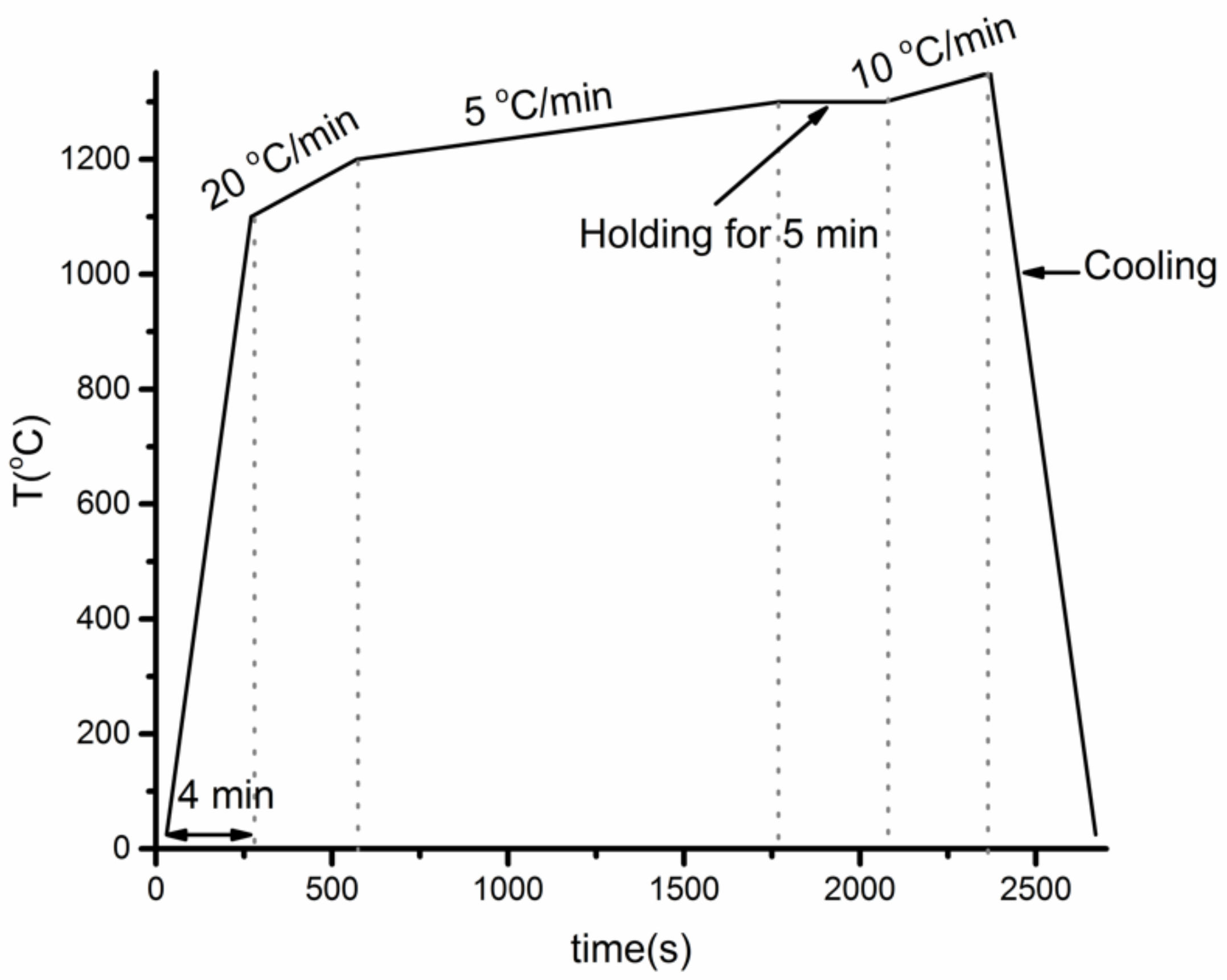
2.3. Thermal Cycle Experiments Procedure

A vertical tube resistance furnace was used in the thermal cycle experiments. A graphite holder was placed inside the furnace. The temperature program of the furnace was controlled by the thermocouple installed on the top of the graphite holder. Since the samples should be placed on the bottom of the graphite holder, the temperature correction occurred before the experiments. The distance from the bottom to the top of the graphite holder was ~50 mm and we found that the temperature at the top position was 19.5 °C higher than at the bottom position. Hence, the temperature program was set 19.5 °C higher to obtain a more accurate temperature for Fe-26Si-9B alloy.
Ten grams of the Fe-26Si-9B master alloy was charged to a Si3N4 crucible. Then, the charged Si3N4 crucible was located at the bottom of the graphite holder. A flow of Ar was kept in the furnace during the experiment. In the heating step, the furnace was heated to 1550 °C at a heating rate of 60 °C/min. Then, a holding time of 60 min was used to affirm the homogeneity of the liquid Fe-26Si-9B alloy. The temperature was later decreased to 1100 °C at a cooling rate of 60 °C/min, and the liquid alloy solidified in the cooling process. A holding time of 10 min was kept at 1100 °C. Subsequently, the temperature was increased to 1300 °C and the solidified alloy was re-melted. A holding time of 10 min was kept at 1300 °C as well. For this work, 1, 6, and 12 thermal cycles were executed on the Si3N4 crucibles. A typical temperature profile is shown in Figure 2. The red cycles represent 1, 6, and 12 melting and solidification stop positions.

2.4. Characterization Method

The microstructures of the samples were characterized both by scanning electron microscopy (SEM) (Zeiss Supra, 55 VP, Oberkochen, Germany) with a backscattered electron (BSE) detector and by an electron probe micro-analyzer (EPMA) (JEOL JXA 8500F, Germany, Freising). Phases were identified by energy dispersive spectroscopy (EDS) and wavelength dispersive X-ray spectroscopy (WDS) techniques. The chemical composition of the Fe-26Si-9B master alloy was analyzed by using an ICP-HR-MS Agilent 8800™ (Santa Clara, CA, USA). FactSage software (version 7.2 and 8.1) [25] was used to calculate the thermodynamic properties based on the FTlite database.

3. Results and Discussion

3.1. Wettability Property of Fe-26Si-9B Alloy on Si3N4 Substrate

A non-wetting behavior was observed based on the Fe-26Si-9B/Si3N4 wetting experiment. The sample photos during the wetting experiment in the heating–cooling process is shown in Figure 3. The Fe-26Si-9B particle started to melt at ~1218 °C, and completely melted at 1250 °C. At 1300 °C, an equilibrium physical state was reached between the molten Fe-26Si-9B droplet and Si3N4 substrate. At this point, the function of the contact angle between the liquid Fe-26Si-9B and Si3N4 substrate with time was recorded, as shown in Figure 4. The contact angle was steady at the equilibrium state, and an average value of ~143° was measured. Gao et al. [26] investigated the wettability behavior between Fe-5.3Si-3B alloy and BN substrates, and they found that Si3N4 was produced at the interface, which is characterized as reactive wetting. For this reason, their wetting behavior was governed by the reactive production of Si3N4. They measured the contact angle to be in the range 140–147° at 1160–1360 °C under a vacuum, which corresponds to our result. The non-wetting behavior prevented the liquid Fe-26Si-9B alloy from penetrating inside of the Si3N4 crucible and further avoided the degradation of the Si3N4 container with time and temperature cycles.

3.2. Phase Stability

Intermetallic FeB, FeSi, SiB6, and FeSiB3 compounds were observed in the Fe-26Si-9B alloys after thermal cycle experiments. The formed phases in the Fe-26Si-9B alloys were observed by SEM-BSE, as shown in Figure 5. FeB, FeSi, SiB6, and FeSiB3 were observed in the bulk of the Fe-26Si-9B alloys, in which the main morphology was a eutectic structure (FeSi + FeSiB3). FeB was found as large crystals, and a small amount of SiB6 was also detected. A thermodynamic calculation was conducted to determine the phases formed in the Fe-Si-B system, as shown in Figure 6. It shows the projection of the Fe-Si-B system calculated by FactSage 7.2 based on the FTlilte database [27]. The blue point represents the eutectic point in the Fe-Si-B system and the red point represents the chemical composition of the master alloys used in the experiments. It showed that the eutectic chemical composition was 65 mass % Fe, 26 mass % Si, and 9 mass % B. A eutectic reaction occurred at 1157 °C, liquid = FeSi + FeB + SiB6, in which FeSi, FeB, and SiB6 formed below the melting temperature. FeSiB3 was not expected from the calculation. The chemical composition of the FeSiB3 phase was further analyzed by EDS with values of 22.0 at. % Fe, 20.6 at. % Si, and 57.3 at. % B, which was different from other well-known ternary compounds, Fe5Si2B, Fe4.7SiB2, and Fe2Si0.4B0.6 [28]. Furthermore, the lattice structure of FeSiB3 was investigated [8] using transmission electron microscopy (TEM). An orthorhombic lattice structure was detected with the unit cell parameters: a = 4.88 Å, b = 10.22 Å, and c = 5.91 Å. Therefore, we confirmed that FeSiB3 was a new phase that was first found in the Fe-Si-B system. These four phases were detected in all the Fe-26Si-9B alloys after 1, 6, and 12 thermal cycles.
FeSi and FeSiB3 were in the form of a eutectic structure in the Fe-26Si-9B alloys. Figure 7 shows the eutectic area in the Fe-26Si-9B alloy after six thermal cycles. The gray area represents the FeSi phase, and the black area represents the FeSiB3 phase. Thus, the phase amounts could be calculated based on the obtained images. The eutectic area consisted of 40% FeSiB3 and 60% FeSi at low magnification (Figure 7a) and 44% FeSiB3 and 56% FeSi at high magnification (Figure 7b). Moreover, the average chemical composition of the detected phases accompanied by the standard deviations is summarized in Table 2. We note that all the analyzed results were obtained by WDS analyses. So, the composition of the eutectic structure could be calculated based on the above results. The average composition of the eutectic point was 36 at. % (61 mass %) Fe, 34 at. % (29 mass %) Si, and 31 at. % (10 mass %) B. These values are close to the theoretical eutectic point of 39 at. % (64 mass %) Fe, 32 at. % (26 mass %) Si, and 29 at. % (9 mass %) B. On that account, the eutectic structure was formed by FeSi and FeSiB3 phases instead of FeSi, FeB, and SiB6 phases based on our experimental results.
The formed phases were stable after 1, 6, and 12 thermal cycle experiments. Comparing the phases formed in the Fe-26Si-9B alloys after thermal cycles in Figure 5, the formed phases did not change with the increase in thermal cycles. In the long-term energy storage process, Fe-26Si-9B alloy will store and release energy by the changes between solid and liquid phases. The highest energy would be achieved when transitioning from a liquid above liquidus temperature to a temperature just below the solidus temperature. Under the solidus temperature, FeB and SiB6 were the primary phases. FeSi and FeSiB3, a eutectic structure, formed with further cooling. The phase stability of Fe-26Si-9B alloy shows the possibility of using the alloy as a PCM.
The Fe-26Si-9B alloy did not introduce nitride phases during the thermal cycle experiments. As shown in both Figure 5 and Figure 7, no nitride phases were detected in the Fe-26Si-9B alloys. Nitrogen solubility in liquid Si has been widely investigated [18,19,20,21,22,23], showing that the solubility of nitrogen is in the range of 4–99.7 ppm mass at the melting point of Si (1414 °C), which is negligible. Nitrogen would be in the form of a boron nitride (BN) phase in the Si melt if the melt is saturated with nitrogen. During research on the high-temperature interaction between Si-B alloys with Si3N4 crucibles [29], the nitrogen solubility was estimated to be lower than 10 ppm mass at 1750 °C. BN precipitates were detected in the solidified Si-B alloys, in which BN particles were embedded in the SiB6 phases. Furthermore, the size of the BN particles was less than 10 µm, which was not easy to find, and it was identified by using high contrast and high magnification in the cross-sectional images. The nitrogen solubility in the Fe-26Si-9B melt was calculated to be 17.1 ppm mass at 1550 °C using Factsage 8.1 based on FTlite database [27]. This value is at the same level as the values in the Si and Si-B melts. It is thought that a small amount of BN forms in Fe-26Si-9B alloys, even though it was not found in the present research. However, the limited amount of BN will not affect the stability of Fe-26Si-9B alloys during the melting and solidification processes.

3.3. Interface of Fe-26Si-9B Alloy and Si3N4

No new phases were produced in the interface between the Fe-26Si-9B alloy and Si3N4 crucibles. Figure 8 shows the distribution of the elements at the interface of the Fe-26Si-9B alloy and Si3N4 crucible after six thermal cycles, in which Si, N, B, and Fe were analyzed. The left bright part shows the Fe-26Si-9B alloy, and the right dark gray part shows the Si3N4 crucible. The dark area between the Fe-26Si-9B alloy and the Si3N4 crucible is the epoxy used for sample preparation. The Fe-26Si-9B alloy did not adhere to the Si3N4 crucible after cooling due to its non-wetting behavior. Fe and B were not detected in the Si3N4 crucible part and nitride phases were not found in the Fe-26Si-9B alloy part. To further study the penetration of the liquid Fe-26Si-9B alloy to the Si3N4 crucible, high-resolution imaging and analysis were performed by EPMA, as shown in Figure 9. Only Si3N4 was identified in this area, and we verified that Si3N4 did not react with liquid Fe-26Si-9B alloy after several melting and solidification steps. The phase evolution in the interaction of Fe-26Si-9B alloy with Si3N4 at 1550 °C was calculated based on the FTlite database [27], as shown in Figure 10. The Y-axis represents the number of phases formed in the interaction between Fe-26Si-9B alloy and Si3N4. The X-axis represents the amount of Fe-26Si-9B alloy. It is theoretically shown that BN would be formed between Fe-26Si-9B alloy and Si3N4 at 1550 °C. However, BN was not experimentally found at the interface. Longer thermal cycle experiments are expected to be conducted to examining the stability of the Si3N4 crucible. In short, no new interlayer phase evolved between the Fe-26Si-9B alloys and Si3N4 crucibles, and hence Si3N4 is inert and is a material that can potentially be used as a container to hold Fe-26Si-9B PCM.

4. Conclusions

Thermal cycle experiments were conducted in the Si3N4 crucibles in the temperature range of 1100–1300 °C to evaluate Si3N4 as an Fe-26Si-9B PCM container. In addition, the wettability property of liquid Fe-26Si-9B on Si3N4 was examined in a sessile drop approach. The following conclusions were drawn based on the experimental and theoretical results:
  • FeSi, FeB, SiB6, and FeSiB3 formed in Fe-26Si-9B alloy after thermal cycle experiments. FeB was in the form of large crystals. FeSi and FeSiB3 were in the form of eutectic structures.
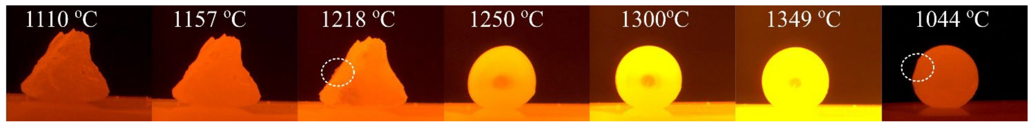
  • Fe-26Si-9B alloy started to melt at ~1218 °C and became completely molten at ~1250 °C, indicating that Fe-26Si-9B alloy is not a eutectic alloy. The eutectic point was calculated to be about 61 mass % Fe, 29 mass % Si, and 10 mass % B (Fe-29Si-10B) in the Fe-Si-B system.
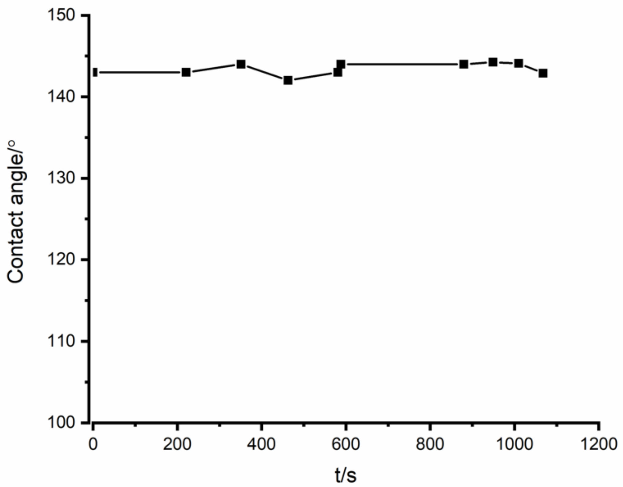
  • In the interaction between Si3N4 and Fe-26Si-9B alloy, the equilibrium contact angle was measured to be ~143°.
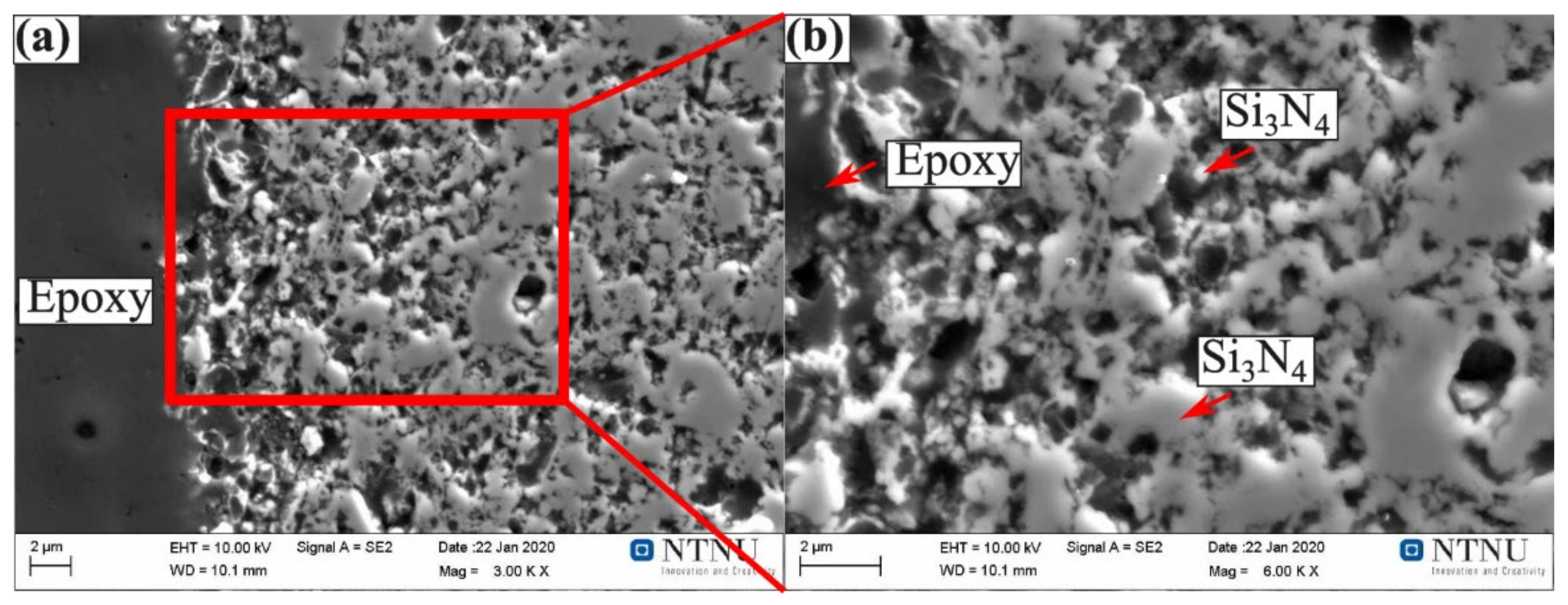
  • No nitride phases were present in Fe-26Si-9B alloy or at their interface. This shows the possibility of using Si3N4 refractory material as an Fe-26Si-9B alloy container at high temperatures.

Author Contributions

Conceptualization: M.T. and J.S.; methodology: M.T.; software: J.J.; validation: M.T., J.S. and J.J.; formal analysis: J.J.; investigation: J.J.; resources: J.J. and M.T.; writing, J.J.; writing—review and editing: J.S. and M.T.; visualization: J.J.; supervision: M.T. and J.S.; project administration: M.T.; funding acquisition: M.T. All authors have read and agreed to the published version of the manuscript.

Funding

The AMADEUS project received funds from the European Union’s Horizon 2020 research and innovation program, FET-OPEN action, under grant agreement 737054. The sole responsibility for the content of this publication lies with the authors. It does not necessarily reflect the opinion of the European Union. Neither the REA nor the European Commission are responsible for any use that may be made of the information contained therein.

Institutional Review Board Statement

Not applicable.

Informed Consent Statement

Not applicable.

Data Availability Statement

Not applicable.

Conflicts of Interest

The authors declare no conflict of interest.

References

  1. IEA Net Zero by 2050. Available online: https://www.iea.org/reports/net-zero-by-2050 (accessed on 10 February 2022).
  2. Kumar, N.; Banerjee, D. Phase change materials. In Handbook of Thermal Science and Engineering; Springer International Publishing: Cham, Switzerland, 2018; pp. 2213–2275. ISBN 9783319266954. [Google Scholar]
  3. Magomedov, A.M. Netraditsionnye Istochniki Energii (Non-Traditional Sources of Energy); Yupiter: Makhachkala, India, 1996. [Google Scholar]
  4. Jiao, J.; Grorud, B.; Sindland, C.; Safarian, J.; Tang, K.; Sellevoll, K.; Tangstad, M. The use of eutectic Fe-Si-B alloy as a phase change material in thermal energy storage systems. Materials 2019, 12, 2312. [Google Scholar] [CrossRef] [PubMed] [Green Version]
  5. Sellevoll, K. Interactions of Eutectic Fe-Si-B Alloy with Graphite Crucibles; Norwegian University of Science and Technology: Trondheim, Norway, 2018. [Google Scholar]
  6. Jayakumari, S. Making of Prototypes: Fe-Si, Fe-Si-B Alloys and SiC-Crucibles for Phase Change Materials (PCMs); Norwegian Univerisity of Science and Technology: Trondheim, Norway, 2019. [Google Scholar]
  7. Grorud, B. Interaction of Eutectic Fe-Si-B Alloy with Graphite Crucibles. Master’s Thesis, Norwegian University of Science and Technology, Trondheim, Norway, 2018. [Google Scholar]
  8. Jiao, J.M. Si-Based Phase Change Materials in Thermal Energy Storage Systems; Norwegian University of Science and Technology (NTNU): Trondheim, Norway, 2020. [Google Scholar]
  9. Grorud, B. Interaction of Liquid Si-B Alloys with Graphite Crucibles; Norwegian University of Science and Technology (NTNU): Trondheim, Norway, 2017. [Google Scholar]
  10. Sellevoll, K. Interactions of FeSi Alloys with Graphite Crucibles. Master’s Thesis, Norwegian University of Science and Technology, Trondheim, Norway, 2019. [Google Scholar]
  11. Datas, A.; Ramos, A.; Martí, A.; del Cañizo, C.; Luque, A. Ultra high temperature latent heat energy storage and thermophotovoltaic energy conversion. Energy 2016, 107, 542–549. [Google Scholar] [CrossRef] [Green Version]
  12. Datas, A.; Cristobal, A.B.; Del Cañizo, C.; Antolín, E.; Beaughon, M.; Nikolopoulos, N.; Nikolopoulos, A.; Zeneli, M.; Sobczak, N.; Polkowski, W.; et al. AMADEUS: Next generation materials and solid state devices for ultra high temperature energy storage and conversion. AIP Conf. Proc. 2018, 2033, 170004. [Google Scholar]
  13. Gilpin, M.R. High Temperature Latent Heat Thermal Energy Storage to Augment Solar Thermal Propulsion for Microsatellites; Defense Technical Information Center: Fort Belvoir, VA, USA, 2015. [Google Scholar]
  14. Rhim, W.K.; Ohsaka, K. Thermophysical properties measurement of molten silicon by high-temperature electrostatic levitator: Density, volume expansion, specific heat capacity, emissivity, surface tension and viscosity. J. Cryst. Growth 2000, 208, 313–321. [Google Scholar] [CrossRef]
  15. Jiao, J.; Safarian, J.; Grorud, B.; Tangstad, M. High temperature interaction of Si-B alloys with graphite crucible in thermal energy storage systems. Materials 2020, 13, 29. [Google Scholar] [CrossRef] [PubMed] [Green Version]
  16. Pielichowska, K.; Pielichowski, K. Phase change materials for thermal energy storage. Prog. Mater. Sci. 2014, 65, 67–123. [Google Scholar] [CrossRef]
  17. Kuravi, S.; Trahan, J.; Goswami, D.Y.; Rahman, M.M.; Stefanakos, E.K. Thermal energy storage technologies and systems for concentrating solar power plants. Prog. Energy Combust. Sci. 2013, 39, 285–319. [Google Scholar] [CrossRef]
  18. Søiland, A.K.; Øvrelid, E.J.; Lohne, O.; Tuset, J.K.; Engh, T.A.; Gjerstad, Ø. Carbon and nitrogen contents and inclusion formation during crystallization of multi-crystalline silicon. In Proceedings of the 19th EUPVSEC, Paris, France, 7–11 June 2004; pp. 7–11. [Google Scholar]
  19. Mitsuru, T.; Toshiharu, F.; Yamauchi, C. Activity of Boron in Molten Silicon. Min. Mater. Process. Inst. Japan 1998, 114, 807–812. [Google Scholar] [CrossRef] [Green Version]
  20. Takeuchi1, M.; Iguchi, Y.; Narushima, T. Nitrogen Solubility in Liquid Silicon. Mater. Trans. JIM 1994, 35, 821–826. [Google Scholar] [CrossRef] [Green Version]
  21. Yoshikawa, T.; Morita, K. Thermodynamic Property of B in Molten Si and Phase Relations in the Si-Al-B System. Mater. Trans. 2005, 46, 1335–1340. [Google Scholar] [CrossRef] [Green Version]
  22. Yatsurugi, Y.; Akiyama, N.; Endo, Y.; Nozaki, T. Concentration, Solubility, and Equilibrium Distribution Coefficients of Nitrogen and Oxygen in Semiconductor Silicon. J. Electrochem. Soc. 1973, 120, 975–978. [Google Scholar] [CrossRef]
  23. Kaiser, W.; Thurmond, C.D. Nitrogen in silicon. J. Appl. Phys. 1959, 30, 427–431. [Google Scholar] [CrossRef]
  24. Ciftja, A.; Engh, T.A.; Tangstad, M. Wetting properties of molten silicon with graphite materials. Metall. Mater. Trans. A Phys. Metall. Mater. Sci. 2010, 41, 3183–3195. [Google Scholar] [CrossRef]
  25. FactSage. Available online: http://www.factsage.com/fs_general.php (accessed on 1 March 2022).
  26. Gao, H.; Dong, B.S.; Zhong, J.; Li, Z.Z.; Xu, M.; Zhou, S.X. The influence of substrate and atmosphere on the properties of FeSiB(Cu,Nb) alloy melts. Sci. China Technol. Sci. 2016, 59, 1892–1898. [Google Scholar] [CrossRef]
  27. Bale, C.W.; Bélisle, E.; Chartrand, P.; Decterov, S.A.; Eriksson, G.; Gheribi, A.E.; Hack, K.; Jung, I.H.; Kang, Y.B.; Melançon, J.; et al. FactSage thermochemical software and databases, 2010–2016. Calphad Comput. Coupling Phase Diagr. Thermochem. 2016, 54, 35–53. [Google Scholar] [CrossRef] [Green Version]
  28. Aronsson, B.; Engström, I. X-Ray Investigations on M-Si-B Systems (M = Mn, Fe, Co). II. Some Features of the Fe-Si-B and Mn-Si-B Systems. Acta Chem. Scand. 1960, 14, 1403–1413. [Google Scholar] [CrossRef] [Green Version]
  29. Jiao, J.M.; Tang, K.; Safarian, J.; Grorud, B.; Sellevoll, K.; Tangstad, M. High temperature interaction between Si–B alloys and Si3N4. Ceram. Int. 2021, 47, 13837–13844. [Google Scholar] [CrossRef]
Figure 1. Temperature profile of the Fe-26Si-9B particle on Si3N4 substrate under 10−4 atm.
Crystals 12 00376 g001
Figure 2. The typical temperature profile in a resistance furnace.
Crystals 12 00376 g002
Figure 3. Photos of the Fe-26Si-9B particle on Si3N4 substrate under 10−4 atm.
Crystals 12 00376 g003
Figure 4. Contact angles as a function of time for the Fe-26Si-9B droplet on Si3N4 substrate after complete melting.
Crystals 12 00376 g004
Figure 5. Images of the Fe-26Si-9B alloys after thermal cycle experiments. (a) one cycle; (b) six cycles; (c) twelve cycles.
Crystals 12 00376 g005
Figure 6. Projection of Fe-Si-B system, where the red point represents the composition of the master Fe-26Si-9B alloy, and the blue point represents the eutectic point. Calculated by FactSage 7.2 based on the FTlite database.
Crystals 12 00376 g006
Figure 7. Images of the eutectic area in the Fe-26Si-9B alloy after six thermal cycles: (a) 200X; (b) 2000X. The red rectangle area shows the magnification position.
Crystals 12 00376 g007
Figure 8. EPMA elemental map at the interface between the Fe-Si-B alloy and Si3N4 crucible wall after six thermal cycles at 1100–1300 °C.
Crystals 12 00376 g008
Figure 9. Images of the interface close to the Si3N4 part: (a) 3000X; (b) 6000X.
Crystals 12 00376 g009
Figure 10. The evolution of the phase formation in the interaction of Fe-26Si-9B alloy with Si3N4 at 1550 °C. Calculated by FactSage 7.2 based on the Ftlite database.
Crystals 12 00376 g010
Table 1. Chemical composition of Fe-26Si-9B master alloy analyzed by ICP-MS (mass %).
SampleSiFeBAlMn
Fe-Si-B25.6563.338.470.180.23
Table 2. The detected phases in the Fe-26Si-9B alloys after experiments. All the values were obtained by WDS analyses and were normalized (at. %).
PhaseFeStd. Dev.SiStd. Dev.BStd. Dev.
FeSi45.5±1.243.2±1.111.3±1.7
FeSiB322.0±1.020.6±1.457.3±0.4
FeB47.7±0.90.23±0.952.0±0.1
SiB60.31±0.110.6±0.289.3±0.2
Publisher’s Note: MDPI stays neutral with regard to jurisdictional claims in published maps and institutional affiliations.

